EP4523856A1 - Elektrowerkzeug mit schwingungsdämpfender struktur - Google Patents
Elektrowerkzeug mit schwingungsdämpfender struktur Download PDFInfo
- Publication number
- EP4523856A1 EP4523856A1 EP24200395.2A EP24200395A EP4523856A1 EP 4523856 A1 EP4523856 A1 EP 4523856A1 EP 24200395 A EP24200395 A EP 24200395A EP 4523856 A1 EP4523856 A1 EP 4523856A1
- Authority
- EP
- European Patent Office
- Prior art keywords
- vibration damping
- power tool
- damping element
- connecting member
- handle
- Prior art date
- Legal status (The legal status is an assumption and is not a legal conclusion. Google has not performed a legal analysis and makes no representation as to the accuracy of the status listed.)
- Pending
Links
Images





Classifications
-
- B—PERFORMING OPERATIONS; TRANSPORTING
- B25—HAND TOOLS; PORTABLE POWER-DRIVEN TOOLS; MANIPULATORS
- B25F—COMBINATION OR MULTI-PURPOSE TOOLS NOT OTHERWISE PROVIDED FOR; DETAILS OR COMPONENTS OF PORTABLE POWER-DRIVEN TOOLS NOT PARTICULARLY RELATED TO THE OPERATIONS PERFORMED AND NOT OTHERWISE PROVIDED FOR
- B25F5/00—Details or components of portable power-driven tools not particularly related to the operations performed and not otherwise provided for
- B25F5/006—Vibration damping means
-
- B—PERFORMING OPERATIONS; TRANSPORTING
- B25—HAND TOOLS; PORTABLE POWER-DRIVEN TOOLS; MANIPULATORS
- B25B—TOOLS OR BENCH DEVICES NOT OTHERWISE PROVIDED FOR, FOR FASTENING, CONNECTING, DISENGAGING, OR HOLDING
- B25B21/00—Portable power-driven screw or nut setting or loosening tools; Attachments for drilling apparatus serving the same purpose
- B25B21/02—Portable power-driven screw or nut setting or loosening tools; Attachments for drilling apparatus serving the same purpose with means for imparting impact to screwdriver blade or nut socket
-
- B—PERFORMING OPERATIONS; TRANSPORTING
- B25—HAND TOOLS; PORTABLE POWER-DRIVEN TOOLS; MANIPULATORS
- B25B—TOOLS OR BENCH DEVICES NOT OTHERWISE PROVIDED FOR, FOR FASTENING, CONNECTING, DISENGAGING, OR HOLDING
- B25B23/00—Details of, or accessories for, spanners, wrenches, screwdrivers
- B25B23/18—Devices for illuminating the head of the screw or the nut
Definitions
- the present disclosure relates to the field of power tools, and particularly to an electric impact tool.
- Some power tools include a member intermittently applying an impact force/torque, which inevitably causes vibration.
- an electric impact tool comprises a hammer that translates and/or rotates to impact an anvil to provide an impact rotational force or intermittently apply a torque to a workpiece (e.g., a fastener) to tighten or loosen the fastener.
- a workpiece e.g., a fastener
- an electric impact wrench may be used to perform processing of a rail, e.g., tightening and loosening bolts on the rail.
- a high torque impact wrench is capable of transmitting a very large amount of torque to the fasteners.
- the impact wrench generates vibration, which may spread over the whole wrench and be transmitted to the operator, and which for example makes the operator's hands tremble so that the operator cannot work for a long time, thereby causing poor use experience to the operator; moreover, these vibrations and impacts can damage the connections between components of the tool, e.g., loosen the connections between the components, or even damage the components themselves.
- vibration damping structure suitable for the above-described power tool and a power tool with the vibration damping structure, to avoid the loosening of components caused by the vibrations, and to give a user a better experience, etc.
- the present disclosure provides an improved power tool, which is provided with a vibration damping structure to avoid the loosening of components caused by vibration, thereby giving the user a better experience, etc.
- the techniques described herein relate to a power tool including: a working portion including a motor housing enclosing a motor; a handle portion including a handle housing; a connecting member having a first end coupled to the handle housing and a second end coupled to the motor housing; and a vibration damping structure configured to reduce transmission of vibration from the motor housing to the handle housing.
- the techniques described herein relate to a power tool, wherein the first end of the connecting member extends into the handle housing, and wherein the second end of the connecting member extends into the motor housing.
- the techniques described herein relate to a power tool, wherein the vibration damping structure includes a first vibration damping element disposed between the first end of the connecting member and the handle housing, and a second vibration damping element disposed between the second end of the connecting member and the motor housing.
- the techniques described herein relate to a power tool, wherein the second vibration damping element has the same shape as the first vibration damping element.
- the techniques described herein relate to a power tool, wherein the first vibration damping element and the second vibration damping element are cylindrical.
- the techniques described herein relate to a power tool, wherein the first end of the connecting member includes a first through hole, wherein the second end of the connecting member includes a second through hole, wherein the first through hole receives a first fastener to couple the first end of the connecting member to the handle housing, and wherein the second through hole receives a second fastener to couple the second end of the connecting member to the motor housing.
- the techniques described herein relate to a power tool, wherein the second vibration damping element includes a connecting through hole aligned with the second through hole.
- the techniques described herein relate to a power tool, wherein one end of the second vibration damping element is provided with an annular rim extending radially inwards from an outer circumference of the second vibration damping element.
- the techniques described herein relate to a power tool, wherein the one end of the second vibration damping element is provided with a circumferential protruding wall extending from an inner circumference of the annular rim in a length direction of the second vibration damping element toward an interior of the second vibration damping element, and wherein an annular space is formed between the circumferential protruding wall and an inner circumferential wall of the second vibration damping element, and wherein the second end of the connecting member is inserted into the annular space.
- the techniques described herein relate to a power tool, further including a carrying handle coupled to the connecting member and located between the handle housing and the motor housing.
- the techniques described herein relate to a power tool, further including a third vibration damping element provided between an end of the carrying handle and the connecting member.
- the techniques described herein relate to a power tool, further including first vibration damping element provided between the handle housing and the first end of the elongated connecting member and a second vibration damping element provided between the motor housing and the second end of the elongated connecting member.
- a power tool including: a working portion including a motor housing enclosing a motor, a gearbox coupled to the motor housing, and a drive assembly including an anvil extending from the gearbox; a handle portion including a handle housing, two gripping portions extending in opposite directions such that the handle portion is generally T-shaped, and a battery receptacle disposed on a side of the handle housing; a connecting member having a first end coupled to the handle housing and a second end coupled to the motor housing; and a vibration damping structure configured to reduce transmission of vibration from the working portion to the handle portion.
- a motor 21 is provided in a motor housing 2, an output shaft 210 of the motor 21 is connected to a gear assembly 22 (e.g., a planetary gear set), and an output of the gear assembly 22 is connected to a drive assembly 23 (or an impact mechanism).
- a gear assembly 22 e.g., a planetary gear set
- an output of the gear assembly 22 is connected to a drive assembly 23 (or an impact mechanism).
- the motor 21, the gear assembly, and the drive assembly 23 are supported by the working portion of the power tool 100.
- the drive assembly 23 may include a camshaft 231, a hammer 232 and an anvil 233.
- Studs are respectively provided on the inner walls of the handle housing 1 and the motor housing 2, at positions corresponding to the first end holes 301 and the second end holes 302, and the studs are sized equivalent to the first end holes 301 and the second end holes 302, whereby the studs may be extended and inserted into the first end holes 301 and the second end holes 302.
- the connecting member 3 By means of the form fitting of the inner wall of the housing with the outer wall of the connecting member 3 and the snap-fitting of the studs on the inner wall with the end holes, the connecting member 3 may be held securely in the housing. Then, fasteners may pass through the housings and studs so that a first end of the connecting member 3 is firmly clamped between the two housing halves of the handle housing 1 and a second end of the connecting member 3 is firmly clamped between the two housing halves of the motor housing 2, so that the connecting member 3 is firmly connected between the handle housing 1 and the motor housing 2.
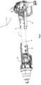
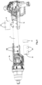
- the vibration damping structure comprises a plurality of vibration damping elements disposed between the connecting member 3 and the handle housing 1 and the motor housing 2, and further comprises vibration damping elements disposed between the connecting member 3 and the carrying handle 4, as described below.
- a first vibration damping element 31 is provided between the first end of the connecting member 3 and the handle housing 1
- a second vibration damping element 32 is provided between the second end of the connecting member 3 and the motor housing 2.
- the vibration damping elements may be made of a resilient material, such as rubber or other resilient material; furthermore, the vibration damping elements may also be embodied in the form of a soft glue or the like. Such materials may be collectively referred to as elastic. For this purpose, a certain clearance space may be left between the connecting member 3 and the inner wall of the handle housing 1 and the inner wall of the motor housing 2, and the vibration damping elements may be filled in the clearance space.
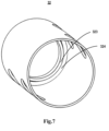
- first vibration damping element 31 and the second vibration damping element 32 show various views of the first vibration damping element 31 and the second vibration damping element 32, wherein the first vibration damping element 31 and the second vibration damping element 32 are identical in terms of construction and shape, so that only the second vibration damping element 32 will be described hereinafter and the description thereof is also applicable to the first vibration damping element 31.
- the second vibration damping element 32 has an overall cylindrical shape, but is not limited thereto, and its shape may change correspondingly according to the shape of the connecting member 3 as described above.
- a length (i.e., a longitudinal dimension) of the second vibration damping element 32 may be the equal to the length of the second end of the connecting member 3 extending into the motor housing 2, i.e., the second vibration damping element 32 is completely located in the motor housing 2 with one end flush with the motor housing 2.
- one end of the second vibration damping element 32 is provided with a rim 322 extending radially inwards from an outer periphery of the second vibration damping element 32, the rim 322 being annular, i.e., an outer circumferential end of the rim 322 is connected to an outer circumferential edge of the second vibration damping element 32 (e.g., to form one piece), while an inner periphery thereof forms a hole for wiring, similar to the hollow interior of the connecting member 3.
- the second vibration damping element 32 when the second vibration damping element 32 is sleeved on the connecting member 3, the second end of the connecting member 3 is inserted in the gap 324, whereby the rim 322 and the gap 324 may function to position to facilitate the mounting of the second vibration damping element 32, i.e., when the second end of the connecting member 3 is inserted and abuts against the gap 324 when the second vibration damping element 32 is sleeved on the connecting member 3, it may be determined that the mounting of the second vibration damping element 32 is completed, as shown in FIG. 6 .
- the rim 322 and the circumferential protruding wall 323 may protect the cable in the connecting member 3, for example, the cable may be in contact with the elastic second vibration damping element 32 without being in contact with the second end of the connecting member 3, thereby preventing the sharp edge of the second end of the connecting member 3 from causing damages to the cable. Furthermore, when the cable is placed in the connecting member 3, even though the tool causes severe vibration during operation, the cable may only be in contact with the second vibration damping element 32 and the inner circumferential surface of the connecting member 3, so that the damages caused by the sharp edge to the cable can be prevented.
- the power tool 1 further comprises a carrying handle 4, also referred to as an assisting handle, which may be used to facilitate carrying when the tool is being transported, e.g., an operator may hold the carrying handle to carry the power tool from one location to another; as another example, when the power tool is operated, the power tool is operated in a vertical orientation, and the operator may hold the carrying handle 4 to assist the power tool in operation.
- a first end of the carrying handle is disposed on the connecting member 3 and a second end thereof is disposed on the motor housing, i.e., the carrying handle is disposed at both ends of the second vibration damping element 32.
- both ends of the carrying handle are connected to the connecting member 3 and located between the handle housing 1 and the motor housing 2.
- the carrying handle 4 may also be divided into two halves, comprising a first carrying handle half 4a and a second carrying handle half 4b.
- the two carrying handle halves are fastened to each other by fasteners, such as bolts.
- the first end of the carrying handle is divided into two halves, each half has a semi-circular cross-section, the two halves, when assembled together, form a circular cross-section adapted to the shape of the circular connecting member 3 so that the first end of the carrying handle is clamped at the periphery of the circular connecting member 3.
- the second end of the carrying handle is connected to the motor housing 2, and a projection is provided at a corresponding connection position on the motor housing.
- the second end of the carrying handle is divided into two halves, each half has an internal profile conforming to the projection, such that the two halves snap over the projection when assembled and are fastened together by fasteners.
- a third vibration damping element 41 is provided which, like the first vibration damping element and the second vibration damping element, is adapted to the shape of the carrying handle and the connecting member.
- the third vibration damping element 41 is, for example, annular, sleeved on the connecting member 3, and disposed at the first end of the carrying handle, between the carrying handle and the connecting member.
- the inner wall of the first end of the carrying handle is provided with a plurality of ribs 401.
- the combination of the ribs has a shape adapted to the shape of the connecting member 3, for example a generally cylindrical shape, so that the ribs 401 press the third vibration damping element against the connecting member 3 when the carrying handle is connected to the connecting member.
- the third vibration damping element makes the connection of the connecting member 3 to the carrying handle firmer and minimizes the loosening of the connection between the two; on the other hand, the third vibration damping element dampens the vibrations during operation of the tool, greatly reduces the damages caused by the vibrations to the carrying handle itself, and reduces the loosening of the connection between the carrying handle and the connecting member due to the vibrations.
- At least one lighting device 5 such as an LED, is disposed at a front end of the working portion to enable the operator to clearly see the surrounding and operation situations of the working element when the power tool operates (such as the light is dark or at night).
- at least one lighting device 5 is disposed at a lower end of the motor housing 2, close to the gearbox.
- the lighting device 5 may illuminate the surrounding of the working element.
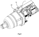
- the lighting device 5 may be disposed between the two motor housing halves 2a and 2b of the motor housing 2.
- each of the motor housing halves 2a and 2b is provided with two recesses 201 at one end near the gearbox, the two recesses 201 are symmetrical with respect to the Z axis, i.e., the two motor housing halves 2a and 2b totally have four recesses 201.
- FIG. 8 only shows one of the recesses 201.
- One lighting device 5 is disposed in each groove, and a total of two lighting devices 5 are disposed in an interface between the two motor housing halves 2a and 2b, i.e., disposed in the recesses 201 at the front end of the working portion.
- the two lighting devices 5 are disposed in front of and behind the gearbox so that when the power tool operates, the working element and the surrounding working region can be illuminated from front and rear.
- the two lighting devices 5 share a switch with the motor.
- the depictions of the shape, arrangement positions, arrangement orientations and number and material composition of the vibration damping elements in the present disclosure are merely examples and are not limiting and are not only limited to arranging the vibration damping elements between the handle housing, the motor housing and the carrying handle and the connecting member. Instead, the vibration damping elements may be arranged correspondingly at different positions according to the type, size, structure and vibration damping and buffering requirements of the power tool, as long as the vibration-damping and buffering effects may be achieved in the power tool and between different components, which all falls within the concept and protection scope of the present disclosure.
- vibration damping structure includes a first vibration damping element disposed between the first end of the connecting member and the handle housing, and a second vibration damping element disposed between the second end of the connecting member and the motor housing.
- Clause 8 The power tool of any one of clauses 3-7, wherein one end of the second vibration damping element is provided with an annular rim extending radially inwards from an outer circumference of the second vibration damping element.
- Clause 11 The power tool of clause 10, further comprising a third vibration damping element provided between an end of the carrying handle and the connecting member.
- Clause 13 The power tool of any preceding clause, further comprising a lighting device is disposed in a recess at a front end of the working portion; and/or wherein the working portion includes a drive assembly comprising a camshaft configured to receive torque from the motor, a camshaft, an anvil, and a hammer is movable along the camshaft to deliver periodic rotational impacts to the anvil.
- a lighting device is disposed in a recess at a front end of the working portion; and/or wherein the working portion includes a drive assembly comprising a camshaft configured to receive torque from the motor, a camshaft, an anvil, and a hammer is movable along the camshaft to deliver periodic rotational impacts to the anvil.
- Clause 14 The power tool of any preceding clause, further comprising a battery pack removably coupled to the handle portion; and/or wherein the handle portion includes two gripping portions extending in opposite directions such that the handle portion is generally T-shaped to facilitate use and operation of the power tool by two hands.
- Clause 15 The power tool of clause 14, further comprising a battery receptacle disposed on a side of the handle housing and configured to receive the battery pack such that the battery pack is offset from a central longitudinal axis of the power tool; and, optionally, wherein the battery pack is slidably coupled to the battery receptacle along a battery axis parallel to the central longitudinal axis.
- a power tool comprising: a working portion including a motor housing enclosing a motor, a gearbox coupled to the motor housing, and a drive assembly including an anvil extending from the gearbox; a handle portion including a handle housing, two gripping portions extending in opposite directions such that the handle portion is generally T-shaped, and a battery receptacle disposed on a side of the handle housing; an elongated connecting member extending along a central longitudinal axis and having a first end coupled to the handle housing and a second end coupled to the motor housing; and a battery pack slidably coupled to the battery receptacle along a battery axis parallel to the central longitudinal axis.
- a power tool comprising: a working portion including a motor housing enclosing a motor, a gearbox coupled to the motor housing, and a drive assembly including an anvil extending from the gearbox; a handle portion including a handle housing, two gripping portions extending in opposite directions such that the handle portion is generally T-shaped, and a battery receptacle disposed on a side of the handle housing; a connecting member having a first end coupled to the handle housing and a second end coupled to the motor housing; and a vibration damping structure configured to reduce transmission of vibration from the working portion to the handle portion.
- Clause 20 The power tool of clause 18 or 19, further comprising a battery pack removably coupled to the handle portion.
Landscapes
- Engineering & Computer Science (AREA)
- Mechanical Engineering (AREA)
- Percussive Tools And Related Accessories (AREA)
- Vibration Prevention Devices (AREA)
Applications Claiming Priority (1)
| Application Number | Priority Date | Filing Date | Title |
|---|---|---|---|
| CN202322498536.8U CN221048350U (zh) | 2023-09-14 | 2023-09-14 | 用于动力工具的减振结构和带有减振结构的动力工具 |
Publications (1)
| Publication Number | Publication Date |
|---|---|
| EP4523856A1 true EP4523856A1 (de) | 2025-03-19 |
Family
ID=91223699
Family Applications (1)
| Application Number | Title | Priority Date | Filing Date |
|---|---|---|---|
| EP24200395.2A Pending EP4523856A1 (de) | 2023-09-14 | 2024-09-13 | Elektrowerkzeug mit schwingungsdämpfender struktur |
Country Status (3)
| Country | Link |
|---|---|
| US (1) | US20250091189A1 (de) |
| EP (1) | EP4523856A1 (de) |
| CN (1) | CN221048350U (de) |
Families Citing this family (3)
| Publication number | Priority date | Publication date | Assignee | Title |
|---|---|---|---|---|
| DE102022134555A1 (de) * | 2022-12-22 | 2024-06-27 | Andreas Stihl Ag & Co. Kg | Handgeführtes Arbeitsgerät |
| CN121696879A (zh) * | 2024-09-20 | 2026-03-20 | 塞母布雷有限公司 | 冲击扳钳 |
| USD1108914S1 (en) * | 2025-01-23 | 2026-01-13 | Cembre S.P.A. | Impact wrench |
Citations (4)
| Publication number | Priority date | Publication date | Assignee | Title |
|---|---|---|---|---|
| GB2429257A (en) * | 2005-08-20 | 2007-02-21 | Bryar Group Ltd | An anti-vibration unit for a petrol impact wrench and an impact wrench incorporating such a unit |
| WO2019074424A1 (en) * | 2017-10-12 | 2019-04-18 | Husqvarna Ab | VEGETATION CUTTING DEVICE WITH POWER SUPPLY |
| EP4056325A1 (de) * | 2021-03-12 | 2022-09-14 | CEMBRE S.p.A. | Schalgwerkzeug |
| US20230121902A1 (en) * | 2021-10-19 | 2023-04-20 | Makita Corporation | Impact tool |
Family Cites Families (7)
| Publication number | Priority date | Publication date | Assignee | Title |
|---|---|---|---|---|
| EP2199024B1 (de) * | 2008-12-16 | 2018-09-05 | Robert Bosch Gmbh | Tragbares angetriebenes Werkzeug |
| US10232500B2 (en) * | 2012-12-17 | 2019-03-19 | Swerea Ivf Ab | Impact machine |
| US9700978B2 (en) * | 2014-01-27 | 2017-07-11 | The Boeing Company | System and method for processing a workpiece |
| GB201518088D0 (en) * | 2015-10-13 | 2015-11-25 | Black & Decker Inc | Pavement Breaker |
| IT201900004275A1 (it) * | 2019-03-25 | 2020-09-25 | Emak Spa | Attrezzo da lavoro dotato di un elemento smorzatore |
| IT201900004273A1 (it) * | 2019-03-25 | 2020-09-25 | Emak Spa | Attrezzo da lavoro dotato di un elemento smorzatore |
| US12569970B2 (en) * | 2022-02-02 | 2026-03-10 | Makita Corporation | Power tool having hammer mechanism |
-
2023
- 2023-09-14 CN CN202322498536.8U patent/CN221048350U/zh active Active
-
2024
- 2024-09-13 US US18/885,109 patent/US20250091189A1/en active Pending
- 2024-09-13 EP EP24200395.2A patent/EP4523856A1/de active Pending
Patent Citations (4)
| Publication number | Priority date | Publication date | Assignee | Title |
|---|---|---|---|---|
| GB2429257A (en) * | 2005-08-20 | 2007-02-21 | Bryar Group Ltd | An anti-vibration unit for a petrol impact wrench and an impact wrench incorporating such a unit |
| WO2019074424A1 (en) * | 2017-10-12 | 2019-04-18 | Husqvarna Ab | VEGETATION CUTTING DEVICE WITH POWER SUPPLY |
| EP4056325A1 (de) * | 2021-03-12 | 2022-09-14 | CEMBRE S.p.A. | Schalgwerkzeug |
| US20230121902A1 (en) * | 2021-10-19 | 2023-04-20 | Makita Corporation | Impact tool |
Also Published As
| Publication number | Publication date |
|---|---|
| US20250091189A1 (en) | 2025-03-20 |
| CN221048350U (zh) | 2024-05-31 |
Similar Documents
| Publication | Publication Date | Title |
|---|---|---|
| EP4523856A1 (de) | Elektrowerkzeug mit schwingungsdämpfender struktur | |
| US8621719B2 (en) | Auxiliary handle | |
| US9931701B1 (en) | Hand tool support device and method | |
| US10272559B2 (en) | Side handle | |
| WO2011111465A1 (ja) | 電動工具におけるソケットの脱落防止構造 | |
| EP3318367B1 (de) | Arbeitsmaschine | |
| JP7237509B2 (ja) | 動力工具およびフック | |
| KR200496923Y1 (ko) | 일체형 드라이브 소켓을 구비하는 토크 렌치 | |
| JP5029878B2 (ja) | 電動工具 | |
| CN223029577U (zh) | 手持式动力工具 | |
| CN114310799B (zh) | 冲击旋转工具附件和工具系统 | |
| JP4872548B2 (ja) | 電動工具 | |
| JP2009167654A (ja) | スクレーパ、スクレーパのアタッチメント、及びスクレーパ装置 | |
| US20220281091A1 (en) | Side handle assembly for power tool | |
| JP6601017B2 (ja) | 作業機 | |
| JP2012139767A (ja) | 締付工具 | |
| CN114310798A (zh) | 冲击旋转工具附件和工具系统 | |
| JP4338469B2 (ja) | 携帯型作業機 | |
| JP5105141B2 (ja) | 打撃動力工具 | |
| US20180297185A1 (en) | Cordless anchor setting tool | |
| JP2510156Y2 (ja) | 深さ調整装置付回転工具 | |
| JP5835811B2 (ja) | ソケット脱落防止具 | |
| JP2013141710A (ja) | 打撃工具 | |
| KR20120025796A (ko) | 파지용 뭉치가 구비된 나사드라이버 비트 및 그것이 설치된 전동드라이버 장치 | |
| JP2012254485A (ja) | 打撃工具 |
Legal Events
| Date | Code | Title | Description |
|---|---|---|---|
| PUAI | Public reference made under article 153(3) epc to a published international application that has entered the european phase |
Free format text: ORIGINAL CODE: 0009012 |
|
| STAA | Information on the status of an ep patent application or granted ep patent |
Free format text: STATUS: THE APPLICATION HAS BEEN PUBLISHED |
|
| AK | Designated contracting states |
Kind code of ref document: A1 Designated state(s): AL AT BE BG CH CY CZ DE DK EE ES FI FR GB GR HR HU IE IS IT LI LT LU LV MC ME MK MT NL NO PL PT RO RS SE SI SK SM TR |
|
| STAA | Information on the status of an ep patent application or granted ep patent |
Free format text: STATUS: REQUEST FOR EXAMINATION WAS MADE |
|
| 17P | Request for examination filed |
Effective date: 20250919 |