EP4523631A1 - Hilfsvorrichtung zum entwerfen eines montierten körpers, hilfsverfahren zum entwerfen eines montierten körpers und hilfsprogramm zum entwerfen eines montierten körpers - Google Patents
Hilfsvorrichtung zum entwerfen eines montierten körpers, hilfsverfahren zum entwerfen eines montierten körpers und hilfsprogramm zum entwerfen eines montierten körpers Download PDFInfo
- Publication number
- EP4523631A1 EP4523631A1 EP23803202.3A EP23803202A EP4523631A1 EP 4523631 A1 EP4523631 A1 EP 4523631A1 EP 23803202 A EP23803202 A EP 23803202A EP 4523631 A1 EP4523631 A1 EP 4523631A1
- Authority
- EP
- European Patent Office
- Prior art keywords
- mounted body
- projection
- reference direction
- positions
- information
- Prior art date
- Legal status (The legal status is an assumption and is not a legal conclusion. Google has not performed a legal analysis and makes no representation as to the accuracy of the status listed.)
- Pending
Links
Images


Classifications
-
- A—HUMAN NECESSITIES
- A61—MEDICAL OR VETERINARY SCIENCE; HYGIENE
- A61B—DIAGNOSIS; SURGERY; IDENTIFICATION
- A61B17/00—Surgical instruments, devices or methods
- A61B17/56—Surgical instruments or methods for treatment of bones or joints; Devices specially adapted therefor
- A61B17/58—Surgical instruments or methods for treatment of bones or joints; Devices specially adapted therefor for osteosynthesis, e.g. bone plates, screws or setting implements
- A61B17/68—Internal fixation devices, including fasteners and spinal fixators, even if a part thereof projects from the skin
- A61B17/80—Cortical plates, i.e. bone plates; Instruments for holding or positioning cortical plates, or for compressing bones attached to cortical plates
-
- A—HUMAN NECESSITIES
- A61—MEDICAL OR VETERINARY SCIENCE; HYGIENE
- A61B—DIAGNOSIS; SURGERY; IDENTIFICATION
- A61B34/00—Computer-aided surgery; Manipulators or robots specially adapted for use in surgery
- A61B34/10—Computer-aided planning, simulation or modelling of surgical operations
-
- G—PHYSICS
- G06—COMPUTING OR CALCULATING; COUNTING
- G06T—IMAGE DATA PROCESSING OR GENERATION, IN GENERAL
- G06T17/00—Three-dimensional [3D] modelling for computer graphics
-
- A—HUMAN NECESSITIES
- A61—MEDICAL OR VETERINARY SCIENCE; HYGIENE
- A61B—DIAGNOSIS; SURGERY; IDENTIFICATION
- A61B17/00—Surgical instruments, devices or methods
- A61B17/56—Surgical instruments or methods for treatment of bones or joints; Devices specially adapted therefor
- A61B2017/568—Surgical instruments or methods for treatment of bones or joints; Devices specially adapted therefor produced with shape and dimensions specific for an individual patient
-
- A—HUMAN NECESSITIES
- A61—MEDICAL OR VETERINARY SCIENCE; HYGIENE
- A61B—DIAGNOSIS; SURGERY; IDENTIFICATION
- A61B34/00—Computer-aided surgery; Manipulators or robots specially adapted for use in surgery
- A61B34/10—Computer-aided planning, simulation or modelling of surgical operations
- A61B2034/108—Computer aided selection or customisation of medical implants or cutting guides
-
- G—PHYSICS
- G06—COMPUTING OR CALCULATING; COUNTING
- G06T—IMAGE DATA PROCESSING OR GENERATION, IN GENERAL
- G06T2210/00—Indexing scheme for image generation or computer graphics
- G06T2210/41—Medical
Definitions
- This invention relates to a mounted body design assistance device, a mounted body design assistance method, and a mounted body design assistance program.
- a mounted body design method for designing a mounted body to be mounted to a biological component surface, which is a surface of a part constituting a living body.
- the mounted body design method described in Patent Literature 1 designs the mounted body to have an inverted surface of the biological component surface.
- Patent Literature 1 Japanese Translation of PCT International Application No. 2021-514726A
- a position at which the mounted body is mounted to the biological component surface (in other words, a mounting position) and orientation of the mounted body relative to the biological component surface when the mounted body is mounted to the biological component surface (in other words, a mounting direction) vary depending on the purpose and use of the mounted body, etc.
- the above mounted body design method has a problem of difficulty to easily design the mounted body suitable for the mounting position and mounting direction.
- a technique for estimating a surface of a bone including a fractured portion when the fractured portion is to be joined. Therefore, the inventors of the present application have considered using the surface of the bone estimated by the above technique as the biological component surface in the mounted body design method.
- One purpose of this invention is to assist in designing the mounted body that can sufficiently fit the biological component surface.
- a mounted body design assistance device assists in designing a mounted body to be mounted to a biological component surface, which is a surface of a part constituting a living body.
- the mounted body design assistance device includes a reference direction information reception unit, a position information reception unit, a projection position information acquisition unit, a smooth surface information acquisition unit, and a mounted body shape information generation unit.
- the reference direction information reception unit receives reference direction information representing a reference direction that is a direction of reference with respect to the biological component surface.
- the position information reception unit receives position information representing a position of a mounted body corresponding area, which is an area corresponding to the mounted body in a reference plane that is a plane perpendicular to the reference direction.
- the projection position information acquisition unit acquires projection position information representing projection positions, where sample positions in the mounted body corresponding area on the reference plane are projected onto the biological component surface in the reference direction, respectively, based on biological component surface shape information representing a three-dimensional shape of the biological component surface, the received reference direction information, and the received position information.
- the smooth surface information acquisition unit acquires smooth surface information representing a smooth surface that is a smooth curved surface defined by using the projection positions as control points based on the acquired projection position information.
- the mounted body shape information generation unit generates mounted body shape information representing a three-dimensional shape of the mounted body so that the mounted body has at least a part of the smooth surface based on the acquired smooth surface information.
- a mounted body design assistance method assists in designing a mounted body to be mounted to a biological component surface, which is a surface of a part constituting a living body.
- the mounted body design assistance method includes
- a mounted body design assistance program causes a computer to execute a process for assisting in designing a mounted body to be mounted to a biological component surface, which is a surface of a part constituting a living body.
- the process includes
- the design of the mounted body that can sufficiently fit the biological component surface can be assisted.
- the mounted body design assistance device includes a reference direction information reception unit, a position information reception unit, a projection position information acquisition unit, a smooth surface information acquisition unit, and a mounted body shape information generation unit.
- the reference direction information reception unit receives reference direction information representing a reference direction that is a direction of reference with respect to the biological component surface.
- the position information reception unit receives position information representing a position of a mounted body corresponding area, which is an area corresponding to the mounted body in a reference plane that is a plane perpendicular to the reference direction.
- the projection position information acquisition unit acquires projection position information representing projection positions, where sample positions in the mounted body corresponding area on the reference plane are projected onto the biological component surface in the reference direction, respectively, based on biological component surface shape information representing a three-dimensional shape of the biological component surface, the received reference direction information, and the received position information.
- the smooth surface information acquisition unit acquires smooth surface information representing a smooth surface that is a smooth curved surface defined by using the projection positions as control points based on the acquired projection position information.
- the mounted body shape information generation unit generates mounted body shape information representing a three-dimensional shape of the mounted body so that the mounted body has at least a part of the smooth surface based on the acquired smooth surface information.
- a user of the mounted body design assistance device can easily generate the mounted body shape information by inputting the reference direction information and the position information to the mounted body design assistance device. Therefore, the mounted body can be easily designed according to the reference direction and the position of the mounted body corresponding area.
- the mounted body shape information is generated so that the mounted body has at least a part of the smooth surface. Therefore, the design of the mounted body that can sufficiently fit the biological component surface can be assisted.
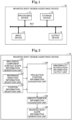
- the mounted body design assistance device 10 includes a processing device 11, a storage device 12, an input device 13, and an output device 14, which are connected to each other via a bus BU1.
- the mounted body design assistance device 10 is constituted by a computer (in other words, information processing device).
- the computer may be a server-type computer, a desktop-type computer, a laptop-type computer, or a tablet-type computer.
- the computer may be at least a part of a stationary game console, a portable game console, a television set, a smartphone, or the like.
- the mounted body design assistance device 10 may be composed of multiple devices communicatively connected to each other.
- the processing device 11 controls the storage device 12, the input device 13, and the output device 14 by executing a program stored in the storage device 12. In this way, the processing device 11 realizes functions described below.
- the processing device 11 is a Central Processing Unit (CPU).
- the processing device 11 may include a Micro Processing Unit (MPU), a Graphics Processing Unit (GPU), or a Digital Signal Processor (DSP) instead of or in addition to a CPU.
- MPU Micro Processing Unit
- GPU Graphics Processing Unit
- DSP Digital Signal Processor
- the storage device 12 includes a volatile memory and a non-volatile memory.
- the storage device 12 includes at least one of a Random Access Memory (RAM), a Read Only Memory (ROM), a semiconductor memory, an organic memory, a Hard Disk Drive (HDD), and a Solid State Drive (SSD).
- RAM Random Access Memory
- ROM Read Only Memory
- HDD Hard Disk Drive
- SSD Solid State Drive
- the input device 13 inputs information from the outside of the mounted body design assistance device 10.
- the input device 13 includes a keyboard and a mouse.
- the input device 13 may include a microphone.
- the output device 14 outputs information to the outside of the mounted body design assistance device 10.
- the output device 14 includes a display.
- the output device 14 may include a speaker.
- the mounted body design assistance device 10 may include a touch panel display that constitutes both the input device 13 and the output device 14.
- the mounted body design assistance device 10 assists in designing a mounted body to be mounted to a biological component surface, which is a surface of a part constituting a living body.
- the part constituting the living body is a bone including a fractured portion.
- the mounted body is a bone plate.
- the part constituting the living body may be a bone not including any fractured portions, or skin.
- the mounted body may be an appliance, or an exercise aid for assisting exercise.
- the functions of the mounted body design assistance device 10 include a biological component surface shape information generation unit 101, a reference direction information reception unit 102, a position information reception unit 103, a projection position information acquisition unit 104, a smooth surface information acquisition unit 105, a mounted body shape information generation unit 106, and an abnormality notification information output unit 107.
- the biological component surface shape information generation unit 101 generates the biological component surface shape information based on biological component shape information representing a three-dimensional shape of the part constituting the living body.
- the biological component shape information may be acquired using a technique called Computed Tomography (CT), Magnetic Resonance Imaging (MRI), Computed Radiography (CR), or Digital Radiography (DR).
- CT Computed Tomography
- MRI Magnetic Resonance Imaging
- CR Computed Radiography
- DR Digital Radiography
- the biological component shape information may be information that complies with a standard called Digital Imaging and Communications in Medicine (DICOM).
- DICOM Digital Imaging and Communications in Medicine
- the biological component shape information is stored in advance in the storage device 12.
- the biological component shape information may be input to the mounted body design assistance device 10 via a recording medium or a communication line.
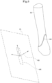
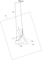
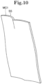
- the reference direction information reception unit 102 and the position information reception unit 103 display the three-dimensional shape of the biological component surface BS represented by the biological component surface shape information generated by the biological component surface shape information generation unit 101 via the output device 14, as illustrated in Figs. 3 and 4 .
- Figs. 3 and 4 illustrate the biological component surface BS viewed from different directions from each other.
- the biological component surface BS includes the fractured portion BR.
- the reference direction information reception unit 102 receives reference direction information representing a reference direction RD that is a direction of reference with respect to the biological component surface BS.
- the position information reception unit 103 receives position information representing a position of a mounted body corresponding area AR, which is an area corresponding to the mounted body in a reference plane PL that is a plane perpendicular to the reference direction RD.
- the mounted body corresponding area AR is rectangular.
- the mounted body corresponding area AR is the smallest rectangular shape that includes the shape of the mounted body.
- the shape of the mounted body may be set based on information input by the user of the mounted body design assistance device 10 via the input device 13. Alternatively, the shape of the mounted body may be set in advance.
- the position information and the reference direction information are input by the user of the mounted body design assistance device 10 via the input device 13.
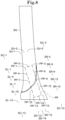
- the projection position information represents N projection positions PP-1 to PP-N, where N sample positions SP-1 to SP-N in the mounted body corresponding area AR on the reference plane PL are projected onto the biological component surface BS in the reference direction RD, respectively.
- N represents an integer of 4 or more. In this example, N represents 15.
- the N sample positions SP-1 to SP-N are located in a grid pattern.
- the N sample positions SP-1 to SP-N are equally spaced at a predetermined short side spacing in the short side direction of the mounted body corresponding area AR, and are equally spaced at a predetermined long side spacing in the long side direction of the mounted body corresponding area AR.
- the short side spacing and the long side spacing are different from each other.
- the short side spacing and the long side spacing may be equal to each other.
- the short side spacing may be set to be longer as the length of the short side of the mounted body corresponding area AR becomes longer.
- the long side spacing may be set to be longer as the length of the long side of the mounted body corresponding area AR becomes longer.
- the long side spacing may be set to be longer as the length of the short side of the mounted body corresponding area AR becomes longer.
- the short side spacing and the long side spacing may be set based on information input by the user of the mounted body design assistance device 10 via the input device 13.
- the projection position information acquisition unit 104 executes a first projection position correction process, a second projection position correction process, and a third projection position correction process.
- the projection position information acquisition unit 104 may not execute at least a part of the first projection position correction process, the second projection position correction process, and the third projection position correction process.
- the projection position information acquisition unit 104 corrects the projection position PP-n for the focused sample position SP-n based on adjacent projection positions, each of which is a projection position for a sample position adjacent to the focused sample position SP-n.
- n represents an integer of 1 to N.
- the projection position PP-n is represented using a Cartesian coordinate system, which has mutually perpendicular x-axis, y-axis, and z-axis with the origin coinciding with the center of gravity of the mounted body corresponding area AR and where the positive direction of the z-axis coincides with the reference direction RD.
- the reference direction component corresponds to the coordinate on the z-axis of the projection position PP-n.
- a magnitude of the reference direction component corresponds to a distance of the projection position PP-n from the reference plane PL.
- the origin of the Cartesian coordinate system may have a position different from the center of gravity of the mounted body corresponding area AR.
- the projection position information acquisition unit 104 acquires the reference direction component of the projection position PP-n for the focused sample position SP-n, which is the sample position SP-n.
- the projection position information acquisition unit 104 determines, for each of the N sample positions SP-1 to SP-N, whether or not the projection position PP-n for the focused sample position SP-n, which is the sample position SP-n, needs to be corrected based on the reference direction component difference acquired for the focused sample position SP-n.
- the reference direction component difference acquired for the focused sample position SP-n having a negative value corresponds to the projection position PP-n for the focused sample position SP-n being closer to the reference plane PL than a parallel plane.
- the parallel plane is a plane that is parallel to the reference plane PL and passes through a position whose coordinate on the z-axis has the reference value.
- the projection position information acquisition unit 104 determines that the projection position PP-n for the focused sample position SP-n needs to be corrected, whereas when the magnitude of the reference direction component difference is equal to or less than the determined second threshold, the projection position information acquisition unit 104 determines that the projection position PP-n for the focused sample position SP-n does not need to be corrected.
- the projection position information acquisition unit 104 corrects the projection position PP-n for the focused sample position SP-n, which is the sample position SP-n, by setting the average value of the reference direction components of projection positions (in other words, correction unnecessity projection positions) that is determined not to need to be corrected among extended adjacent projection positions for the focused sample position SP-n as the reference direction component of the projection position PP-n for the focused sample position SP-n.
- the number of the direct adjacent projection positions is four
- the number of the indirect adjacent projection positions is four.
- the direct adjacent projection positions for the focused sample position SP-5 consist of the projection position PP-2, the projection position PP-4, the projection position PP-6, and the projection position PP-8.
- the indirect adjacent projection positions for the focused sample position SP-5 consist of the projection position PP-1, the projection position PP-3, the projection position PP-7, and the projection position PP-9.
- the number of the direct adjacent projection positions is three, and the number of the indirect adjacent projection positions is two.
- the direct adjacent projection positions for the focused sample position SP-7 consist of the projection position PP-4, the projection position PP-8, and the projection position PP-10.
- the indirect adjacent projection positions for the focused sample position SP-7 consist of the projection position PP-5 and the projection position PP-11.
- the number of the direct adjacent projection positions is two, and the number of the indirect adjacent projection positions is one.
- the direct adjacent projection positions for the focused sample position SP-3 consist of the projection position PP-2 and the projection position PP-6.
- the indirect adjacent projection position for the focused sample position SP-3 consists of the projection position PP-5.
- the projection position information acquisition unit 104 executes the first projection position correction process.
- the projection position information acquisition unit 104 assigns one of two values being a first value or a second value to each of the N sample positions SP-1 to SP-N by binarizing the reference direction components of the N projection positions PP-1 to PP-N for the N sample positions SP-1 to SP-N.
- the projection position information acquisition unit 104 corrects the projection position PP-n for the focused sample position SP-n based on adjacent projection positions, each of which is a projection position for a sample position adjacent to the focused sample position SP-n.
- the projection position information acquisition unit 104 acquires, for each of the N sample positions SP-1 to SP-N, the reference direction component of the projection position PP-n for the focused sample position SP-n, which is the sample position SP-n.
- the projection position information acquisition unit 104 determines a binarization threshold for binarizing the reference direction components of the N projection positions PP-n based on the reference direction components of the N projection positions PP-1 to PP-N acquired for the N sample positions SP-1 to SP-N, respectively.
- the binarization threshold is determined using a method called Otsu's binarization method (in other words, Otsu's method).
- the projection position information acquisition unit 104 assigns the first value to the focused sample position SP-n, which is the sample position SP-n, when the reference direction component of the projection position PP-n for the focused sample position SP-n is smaller than the binarization threshold, whereas the projection position information acquisition unit 104 assigns the second value to the focused sample position SP-n when the reference direction component of the projection position PP-n for the focused sample position SP-n is equal to or greater than the binarization threshold.
- the second value is greater than the first value.
- the first value may be 0, and the second value may be 1.
- the projection position information acquisition unit 104 corrects, for each of the N sample positions SP-1 to SP-N, the projection position PP-n for the focused sample position SP-n, which is the sample position SP-n, by setting the average value of the reference direction components of all extended adjacent projection positions for the focused sample position SP-n as the reference direction component of the projection position PP-n for the focused sample position SP-n when a value assigned to the focused sample position SP-n is isolated.
- the isolation of a value assigned to the focused sample position SP-n corresponds to a value different from a value assigned to the focused sample position SP-n being assigned to all of the direct adjacent sample positions for the focused sample position SP-n.
- the isolation of a value assigned to the focused sample position SP-n may correspond to a value different from a value assigned to the focused sample position SP-n being assigned to all of the direct adjacent sample positions and indirect adjacent sample positions for the focused sample position SP-n.
- the projection position information acquisition unit 104 executes the second projection position correction process.
- the projection position information acquisition unit 104 determines whether or not the biological component surface BS is present on the straight line (in other words, projection line) that passes through the focused sample position SP-n, which is the sample position SP-n, and extends in the reference direction RD.
- the projection position information acquisition unit 104 determines the projection position PP-n for the focused sample position SP-n, which is the sample position SP-n, by setting the average value of the reference direction components of projection positions (in other words, present projection positions), for which it is determined that the biological component surface BS is present on the projection line, among the extended adjacent projection positions for the focused sample position SP-n as the reference direction component of the projection position PP-n for the focused sample position SP-n.
- the projection position information acquisition unit 104 executes the third projection position correction process.
- the smooth surface information acquisition unit 105 acquires auxiliary position information based on the projection position information acquired by the projection position information acquisition unit 104.
- the auxiliary position information represents M auxiliary positions.
- M represents an integer of 2 or more.
- M represents the number (in this example, 20), which is the number (in this example, 16) of sample positions SP-n located on the four sides that constitute the outer edge of the mounted body corresponding area AR plus the number (in this example, 4) of sample positions SP-n located at the corners that constitute the outer edge of the mounted body corresponding area AR.
- the M auxiliary positions include six short side extended auxiliary positions SU-1, SU-2, SU-3, SD-13, SD-14, SD-15, ten long side extended auxiliary positions SR-3, SR-6, SR-9, SR-12, SR-15, SL-1, SL-4, SL-7, SL-10, SL-13, and four corner extended auxiliary positions SC-1, SC-3, SC-13, SC-15.
- the short side extended auxiliary position has a position acquired by moving a projection position PP-n for a sample position SP-n located on the two short sides that constitute the outer edge of the mounted body corresponding area AR in a short side extended direction by a short side extended distance.
- the short side extended direction is a direction perpendicular to each of the short side, on which the sample position SP-n for the projection position PP-n to be moved is located, and the reference direction RD, and is directed outward for the mounted body corresponding area AR.
- the short side extended distance is longer than the interval between sample positions SP-n in the short side extended direction (in other words, long side spacing).
- the short side extended distance is set to be longer as the length of the short side of the mounted body corresponding area AR becomes longer, and to be longer as the length of the long side of the mounted body corresponding area AR becomes longer.
- the three short side extended auxiliary positions SU-1, SU-2, SU-3 have positions acquired by moving the three projection positions PP-1, PP-2, PP-3 for the three sample positions SP-1, SP-2, SP-3 located on the short side that constitutes the outer edge of the mounted body corresponding area AR in the short side extended direction by the short side extended distance, respectively. Therefore, the reference direction components of the three short side extended auxiliary positions SU-1, SU-2, SU-3 respectively coincide with the reference direction components of the three projection positions PP-1, PP-2, PP-3.
- the long side extended auxiliary position has a position acquired by moving a projection position PP-n for a sample position SP-n located on the two long sides that constitute the outer edge of the mounted body corresponding area AR in a long side extended direction by a long side extended distance.
- the long side extended direction is a direction perpendicular to each of the long side, on which the sample position SP-n for the projection position PP-n to be moved is located, and the reference direction RD, and is directed outward for the mounted body corresponding area AR.
- the long side extended distance is longer than the interval between sample positions SP-n in the long side extended direction (in other words, short side spacing).
- the long side extended distance is set to be longer as the length of the short side of the mounted body corresponding area AR becomes longer, and to be longer as the length of the long side of the mounted body corresponding area AR becomes longer.
- the long side extended distance is longer than the short side extended distance.
- the five long side extended auxiliary positions SR-3, SR-6, SR-9, SR-12, SR-15 have positions acquired by moving the five projection positions PP-3, PP-6, PP-9, PP-12, PP-15 for the five sample positions SP-3, SP-6, SP-9, SP-12, SP-15 located on the long side that constitutes the outer edge of the mounted body corresponding area AR in the long side extended direction by the long side extended distance, respectively. Therefore, the reference direction components of the five long side extended auxiliary positions SR-3, SR-6, SR-9, SR-12, SR-15 respectively coincide with the reference direction components of the five projection positions PP-3, PP-6, PP-9, PP-12, PP-15.
- the corner extended auxiliary position has a position acquired by moving a projection position PP-n for a sample position SP-n located on the four corners that constitute the outer edge of the mounted body corresponding area AR in the short side extended direction by the short side extended distance and in the long side extended direction by the long side extended distance.
- the corner extended auxiliary position SC-13 has a position acquired by moving the projection position PP-13 for the sample position SP-13, which is located at the corner that constitutes the outer edge of the mounted body corresponding area AR, by the short side extended distance in the short side extended direction and by the long side extended distance in the long side extended direction. Therefore, the reference direction component of the corner extended auxiliary position SC-13 coincides with the reference direction component of the projection position PP-13.
- the smooth surface information acquisition unit 105 acquires smooth surface information representing a smooth surface SS that is a smooth curved surface defined by using the N projection positions PP-1 to PP-N represented by the projection position information acquired by the projection position information acquisition unit 104 and the M auxiliary positions SU-1, SU-2, SU-3, SD-13, SD-14, SD-15, SR-3, SR-6, SR-9, SR-12, SR-15, SL-1, SL-4, SL-7, SL-10, SL-13, SC-1, SC-3, SC-13, SC-15 represented by acquired correction position information as control points.
- the smooth surface SS is a B-Spline surface.
- the smooth surface may be a spline surface other than a B-spline surface (for example, a NURBS (Non-Uniform Rational B-Spline) surface), or a Bezier surface.
- the smooth surface information acquisition unit 105 may acquire the smooth surface information representing a smooth surface SS that is a smooth curved surface defined by using only the N projection positions PP-1 to PP-N as control points, without using the auxiliary positions as control points.
- the mounted body shape information generation unit 106 generates mounted body shape information representing a three-dimensional shape of the mounted body so that the mounted body has at least a part (for example, a part or all) of the smooth surface SS represented by the smooth surface information based on the smooth surface information acquired by the smooth surface information acquisition unit 105.
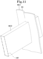
- the mounted body shape information generation unit 106 generates first moving solid body information representing a three-dimensional shape of a first moving solid body MC1 formed by moving the smooth surface SS by a first distance along the reference direction RD (in this example, in the opposite direction to the reference direction RD).
- the mounted body shape information generation unit 106 generates second moving solid body information representing a three-dimensional shape of a second moving solid body MC2 formed by moving the mounted body corresponding area AR along the reference direction RD (in this example, toward the reference direction RD) by a second distance longer than the first distance.
- the mounted body shape information generation unit 106 generates intersection solid body information representing a three-dimensional shape of an intersection solid body CC generated by intersecting the first moving solid body MC1 and the second moving solid body MC2 based on the generated first moving solid body information and second moving solid body information.
- the mounted body shape information generation unit 106 generates mounted body shape information based on the generated intersection solid body information.
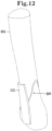
- the mounted body shape information generation unit 106 generates the mounted body shape information, which represents a three-dimensional shape in which at least a part of corners of the intersection solid body CC represented by the intersection solid body information have been rounded (in other words, at least a part of corners of the intersection solid body CC have been filleted) as a three-dimensional shape of the mounted body.
- the mounted body shape information generation unit 106 may generate the mounted body shape information, which represents a three-dimensional shape of the intersection solid body CC represented by the intersection solid body information as a three-dimensional shape of the mounted body.
- the abnormality notification information output unit 107 determines whether or not a process abnormality condition is satisfied based on the projection position information acquired by the projection position information acquisition unit 104. In this example, the abnormality notification information output unit 107 makes the above determination based on the projection position information acquired before executing the first projection position correction process, the second projection position correction process, and the third projection position correction process.
- the abnormality notification information output unit 107 When the process abnormality condition is satisfied, the abnormality notification information output unit 107 outputs, via the output device 14, abnormality notification information indicating that the mounted body shape information cannot be generated normally.
- the functions of the mounted body design assistance device 10 may not include the abnormality notification information output unit 107.
- the description of the functions of the mounted body design assistance device 10 may be supplemented by the following description of an operation of the mounted body design assistance device 10.
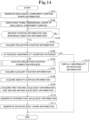
- the mounted body design assistance device 10 generates the biological component surface shape information (step S101 in Fig. 14 ).
- the mounted body design assistance device 10 waits until receiving the position information that represents the position of the mounted body corresponding area AR on the reference plane PL, and the reference direction information that represents the reference direction RD ("No" route of step S103 in Fig. 14 ).
- the mounted body design assistance device 10 may execute the second projection position correction process before the first projection position correction process.
- the mounted body design assistance device 10 executes a loop process (steps S201 to S205) in which each of the N sample positions SP-1 to SP-N is used as a processing target one by one in sequence.
- the mounted body design assistance device 10 determines whether or not the biological component surface BS is present on the straight line (in other words, projection line), which passes through the focused sample position SP-n, which is the sample position SP-n being the processing target, and extends in the reference direction RD (step S202 in Fig. 15 ).
- the mounted body design assistance device 10 determines "Yes" in step S202, and stores presence information indicating that the biological component surface BS is present in association with the focused sample position SP-n (step S203 in Fig. 15 ).
- the mounted body design assistance device 10 determines "No" in step S202, and stores absence information indicating that the biological component surface BS is not present in association with the focused sample position SP-n (step S204 in Fig. 15 ).
- the mounted body design assistance device 10 executes the above loop process (steps S201 to S205) for all of the N sample positions SP-1 to SP-N, and then proceeds to step S206.
- the mounted body design assistance device 10 executes a loop process (steps S206 to S208) in which each of absence sample positions SP-n, which are sample positions associated with the absence information in step S204 among the N sample positions SP-1 to SP-N, is used as a processing target one by one in sequence.
- the mounted body design assistance device 10 executes the above loop process (steps S206 to S208) for all of the absence sample positions SP-n, and then ends the process of Fig. 15 .
- the mounted body design assistance device 10 executes a loop process (steps S301 to S303) in which each of the N sample positions SP-1 to SP-N is used as a processing target one by one in sequence.
- the mounted body design assistance device 10 acquires the reference direction component of the projection position PP-n for the focused sample position SP-n, which is the sample position SP-n being the processing target (step S302 in Fig. 16 ).
- the mounted body design assistance device 10 executes the above loop process (steps S301 to S303) for all of the N sample positions SP-1 to SP-N, and then proceeds to step S304.
- the mounted body design assistance device 10 determines the reference value, the first threshold, and the second threshold based on the reference direction components of the N projection positions PP-1 to PP-N acquired for the N sample positions SP-1 to SP-N, respectively, in step S302 (step S304 in Fig. 16 ).
- the mounted body design assistance device 10 executes a loop process (steps S305 to S312) in which each of the N sample positions SP-1 to SP-N is used as a processing target one by one in sequence.
- the mounted body design assistance device 10 acquires the reference direction component difference which is a value acquired by subtracting the reference value determined in step S304 from the reference direction component of the projection position PP-n for the focused sample position SP-n, which is the sample position SP-n being the processing target (step S306 in Fig. 16 ).
- the mounted body design assistance device 10 determines whether or not the reference direction component difference acquired in step S306 is smaller than 0 (step S307 in Fig. 16 ).
- the mounted body design assistance device 10 determines "Yes” in step S307, and determines whether or not the magnitude of the reference direction component difference is larger than the first threshold determined in step S304 (step S308 in Fig. 16 ).
- the mounted body design assistance device 10 determines "Yes” in step S308, and stores correction necessity information indicating that the projection position PP-n for the focused sample position SP-n needs to be corrected in association with the focused sample position SP-n (step S309 in Fig. 16 ).
- the mounted body design assistance device 10 determines "No" in step S308, and stores correction unnecessity information indicating that the projection position PP-n for the focused sample position SP-n does not need to be corrected in association with the focused sample position SP-n (step S310 in Fig. 16 ).
- the mounted body design assistance device 10 determines "No" in step S307, and determines whether or not the magnitude of the reference direction component difference is greater than the second threshold determined in step S304 (step S311 in Fig. 16 ).
- the mounted body design assistance device 10 determines "Yes" in step S311, and stores correction necessity information indicating that the projection position PP-n for the focused sample position SP-n needs to be corrected in association with the focused sample position SP-n (step S309 in Fig. 16 ).
- the mounted body design assistance device 10 determines "No" in step S311, and stores correction unnecessity information indicating that the projection position PP-n for the focused sample position SP-n does not need to be corrected in association with the focused sample position SP-n (step S310 in Fig. 16 ).
- the mounted body design assistance device 10 executes the above loop process (steps S305 to S312) for all of the N sample positions SP-1 to SP-N, and then proceeds to step S313.
- the mounted body design assistance device 10 executes a loop process (steps S313 to S315) in which each of the correction necessity sample positions SP-n, which are sample positions SP-n associated with the correction necessity information in step S309 among the N sample positions SP-1 to SP-N, is used as a processing target one by one in sequence.
- the mounted body design assistance device 10 corrects the projection position PP-n for the focused sample position SP-n, which is the correction necessity sample position SP-n being the processing target, by setting the average value of the reference direction components of projection positions (in other words, correction unnecessity projection positions) for sample positions associated with the correction unnecessity information among the extended adjacent projection positions for the focused sample position SP-n as the reference direction component of the projection position PP-n for the focused sample position SP-n (step S314 in Fig. 16 ).
- the mounted body design assistance device 10 executes the above loop process (steps S313 to S315) for all of the correction necessity sample positions SP-n, and then ends the process of Fig. 16 .
- the mounted body design assistance device 10 acquires the reference direction component of the projection position PP-n for the focused sample position SP-n, which is the sample position SP-n being the processing target (step S402 in Fig. 17 ).
- the mounted body design assistance device 10 executes the above loop process (steps S401 to S403) for all of the N sample positions SP-1 to SP-N, and then proceeds to step S404.
- the mounted body design assistance device 10 executes a loop process (steps S405 to S409) in which each of the N sample positions SP-1 to SP-N is used as a processing target one by one in sequence.
- the mounted body design assistance device 10 determines whether or not the reference direction component of the projection position PP-n for the focused sample position SP-n, which is the sample position SP-n being the processing target, is smaller than the binarization threshold determined in step S404 (step S406 in Fig. 17 ).
- the mounted body design assistance device 10 determines "No" in step S406, and assigns the second value to the focused sample position SP-n by storing second value information representing the second value in association with the focused sample position SP-n (step S408 in Fig. 17 ).
- the mounted body design assistance device 10 executes the above loop process (steps S405 to S409) for all of the N sample positions SP-1 to SP-N, and then proceeds to step S410.
- the mounted body design assistance device 10 determines whether or not the value assigned to the focused sample position SP-n, which is the sample position SP-n being the processing target, is isolated (step S411 in Fig. 17 ).
- the mounted body design assistance device 10 determines "Yes" in step S411, and corrects the projection position PP-n for the focused sample position SP-n by setting the average value of the reference direction components of all extended adjacent projection positions for the focused sample position SP-n as the reference direction component of the projection position PP-n for the focused sample position SP-n (step S412 in Fig. 17 ).
- the mounted body design assistance device 10 determines "No" in step S411, and proceeds to step S413 without executing the process of step S412.
- the mounted body design assistance device 10 executes the above loop process (steps S410 to S413) for all of the N sample positions SP-1 to SP-N, and then ends the process of Fig. 17 .
- the mounted body design assistance device 10 executes the projection position correction process in step S106 in Fig. 14 .
- the mounted body design assistance device 10 acquires the auxiliary position information based on the projection position information representing the N projection positions PP-1 to PP-N corrected in step S106 (step S107 in Fig. 14 ).
- the mounted body design assistance device 10 acquires the smooth surface information based on the projection position information representing the N projection positions PP-1 to PP-N corrected in step S106 and the auxiliary position information acquired in step S107 (step S108 in Fig. 14 ).
- the mounted body design assistance device 10 acquires the first moving solid body information and the second moving solid body information based on the smooth surface information acquired in step S108, and based on the position information and the reference direction information received in step S103 (step S109 in Fig. 14 ).
- the mounted body design assistance device 10 generates the intersection solid body information based on the first moving solid body information and the second moving solid body information acquired in step S109 (step S110 in Fig. 14 ).
- the mounted body design assistance device 10 generates the mounted body shape information based on the intersection solid body information generated in step S110 (step S111 in Fig. 14 ).
- the mounted body design assistance device 10 ends the process of Fig. 14 .
- step S105 When the process abnormality condition is satisfied in step S105, the mounted body design assistance device 10 determines "Yes" in step S105, and proceeds to step S112. Next, the mounted body design assistance device 10 outputs the abnormality notification information via the output device 14. Next, the mounted body design assistance device 10 ends the process of Fig. 14 without executing the process from step S106 to step S111.
- the mounted body design assistance device 10 of the first embodiment assists in designing a mounted body to be mounted to a biological component surface BS, which is a surface of a part constituting a living body.
- the mounted body design assistance device 10 includes a reference direction information reception unit 102, a position information reception unit 103, a projection position information acquisition unit 104, a smooth surface information acquisition unit 105, and a mounted body shape information generation unit 106.
- the reference direction information reception unit 102 receives reference direction information representing a reference direction RD that is a direction of reference with respect to the biological component surface BS.
- the position information reception unit 103 receives position information representing a position of a mounted body corresponding area AR, which is an area corresponding to the mounted body in a reference plane PL that is a plane perpendicular to the reference direction RD.
- the projection position information acquisition unit 104 acquires projection position information representing projection positions PP-1 to PP-N, where the sample positions SP-1 to SP-N in the mounted body corresponding area AR on the reference plane PL are projected onto the biological component surface BS in the reference direction RD, respectively, based on biological component surface shape information representing a three-dimensional shape of the biological component surface BS, the received reference direction information, and the received position information.
- the smooth surface information acquisition unit 105 acquires smooth surface information representing a smooth surface SS that is a smooth curved surface defined by using the projection positions PP-1 to PP-N as control points based on the acquired projection position information.
- the mounted body shape information generation unit 106 generates mounted body shape information representing a three-dimensional shape of the mounted body so that the mounted body has at least a part of the smooth surface SS based on the acquired smooth surface information.
- the user of the mounted body design assistance device 10 can easily generate the mounted body shape information by inputting the reference direction information and the position information to the mounted body design assistance device 10.
- the mounted body can be easily designed according to the reference direction RD and the position of the mounted body corresponding area AR.
- the mounted body design assistance device 10 the mounted body shape information is generated so that the mounted body has at least a part of the smooth surface SS. Therefore, the design of the mounted body that can sufficiently fit the biological component surface BS can be assisted.
- the mounted body shape information generation unit 106 generates intersection solid body information representing a three-dimensional shape of an intersection solid body CC generated by intersecting a first moved solid body MC1 formed by moving the smooth surface SS by a first distance along the reference direction RD, and a second moved solid body MC2 formed by moving the mounted body corresponding area AR by a second distance longer than the first distance along the reference direction RD, and generates the mounted body shape information based on the generated intersection solid body information.
- the mounted body which has the shape of the mounted body corresponding area AR when the mounted body is viewed in the reference direction RD, and is a plate-like body that fits the biological component surface BS, can be easily designed. Therefore, for example, a bone plate, which is mounted to a surface of a bone including a fractured portion in order to fix the fractured portion, can be easily designed.
- the mounted body design assistance device 10 of the first embodiment is rectangular, and the sample positions SP-1 to SP-N are located in a grid pattern.
- the degree to which the smooth surface SS fits the biological component surface BS (in other words, the fitness degree of the smooth surface SS for the biological component surface BS) can be easily adjusted.
- the smooth surface information acquisition unit 105 uses, for each of four sides constituting an outer edge of the mounted body corresponding area AR, auxiliary positions SU-1, SU-2, SU-3, SD-13, SD-14, SD-15, SR-3, SR-6, SR-9, SR-12, SR-15, SL-1, SL-4, SL-7, SL-10, SL-13, SC-1, SC-3, SC-13, SC-15 acquired by moving a projection position PP-n for a sample position SP-n located on the side in an extension direction, which is perpendicular to each of the side and the reference direction RD and is toward the outside of the mounted body corresponding area AR, as the control points in addition to the projection positions PP-1 to PP-N.
- the projection position information acquisition unit 104 corrects a projection position PP-n for a focused sample position SP-n, which is one of the sample positions SP-1 to SP-N, based on a projection position for a sample position adjacent to the focused sample position SP-n when a magnitude of a difference between a component in the reference direction RD of the projection position PP-n for the focused sample position SP-n, and a reference value is greater than a threshold.
- the mounted body design assistance device 10 can correct a projection position PP-n with an excessive difference between the component in the reference direction RD of the projection position PP-n and the reference value. Therefore, the fitness degree of the smooth surface SS for the biological component surface BS can be prevented from being excessively low.
- the projection position information acquisition unit 104 assigns one of two values being a first value or a second value to each of the sample positions SP-1 to SP-N by binarizing components in the reference direction RD of the projection positions PP-1 to PP-N for the sample positions SP-1 to SP-N, and corrects a projection position PP-n for a focused sample position SP-n, which is one of the sample positions SP-1 to SP-N, based on a projection position for a sample position adjacent to the focused sample position SP-n when a value different from a value assigned to the focused sample position SP-n is assigned to all sample positions adjacent to the focused sample position SP-n.
- the mounted body design assistance device 10 can correct the projection position PP-n, whose component in the reference direction RD differs excessively from a projection position adjacent to the projection position PP-n. Therefore, the fitness degree of the smooth surface SS for the biological component surface BS can be prevented from being excessively low.
- the projection position information acquisition unit 104 determines a projection position PP-n for a focused sample position SP-n, which is one of the sample positions SP-1 to SP-N, based on a projection position for a sample position adjacent to the focused sample position SP-n when the biological component surface BS is not present on a straight line that passes through the focused sample position SP-n and extends in the reference direction RD.
- the mounted body design assistance device 10 when the biological component surface BS is not present on the straight line, which passes through the sample position SP-n and extends in the reference direction RD, the projection position PP-n for the sample position SP-n is determined based on a projection position adjacent to the projection position PP-n. Therefore, the fitness degree of the smooth surface SS for the biological component surface BS can be prevented from being excessively low.
- the mounted body design assistance device 10 of the first embodiment includes an abnormality notification information output unit 107 that outputs abnormality notification information indicating that the mounted body shape information cannot be generated normally when a ratio of the number of sample positions SP-n, each of which a straight line extending in the reference direction RD passes through, the biological component surface BS not being present on the straight line, among the sample positions SP-1 to SP-N to a total number of the sample positions SP-1 to SP-N is greater than an abnormality threshold.
- the mounted body design assistance device 10 can make the user aware of the possibility that the mounted body may not sufficiently fit the biological component surface BS.
Landscapes
- Health & Medical Sciences (AREA)
- Engineering & Computer Science (AREA)
- Life Sciences & Earth Sciences (AREA)
- Orthopedic Medicine & Surgery (AREA)
- Surgery (AREA)
- General Health & Medical Sciences (AREA)
- Biomedical Technology (AREA)
- Heart & Thoracic Surgery (AREA)
- Medical Informatics (AREA)
- Molecular Biology (AREA)
- Animal Behavior & Ethology (AREA)
- Nuclear Medicine, Radiotherapy & Molecular Imaging (AREA)
- Public Health (AREA)
- Veterinary Medicine (AREA)
- Physics & Mathematics (AREA)
- Robotics (AREA)
- Neurology (AREA)
- Computer Graphics (AREA)
- Geometry (AREA)
- Software Systems (AREA)
- General Physics & Mathematics (AREA)
- Theoretical Computer Science (AREA)
- Apparatus For Radiation Diagnosis (AREA)
- Surgical Instruments (AREA)
- Measurement Of The Respiration, Hearing Ability, Form, And Blood Characteristics Of Living Organisms (AREA)
- Processing Or Creating Images (AREA)
Applications Claiming Priority (2)
| Application Number | Priority Date | Filing Date | Title |
|---|---|---|---|
| JP2022077803A JP7141779B1 (ja) | 2022-05-10 | 2022-05-10 | 装着体設計支援装置、装着体設計支援方法、及び、装着体設計支援プログラム |
| PCT/JP2023/004361 WO2023218711A1 (ja) | 2022-05-10 | 2023-02-09 | 装着体設計支援装置、装着体設計支援方法、及び、装着体設計支援プログラム |
Publications (2)
| Publication Number | Publication Date |
|---|---|
| EP4523631A1 true EP4523631A1 (de) | 2025-03-19 |
| EP4523631A4 EP4523631A4 (de) | 2026-04-15 |
Family
ID=83400877
Family Applications (1)
| Application Number | Title | Priority Date | Filing Date |
|---|---|---|---|
| EP23803202.3A Pending EP4523631A4 (de) | 2022-05-10 | 2023-02-09 | Hilfsvorrichtung zum entwerfen eines montierten körpers, hilfsverfahren zum entwerfen eines montierten körpers und hilfsprogramm zum entwerfen eines montierten körpers |
Country Status (4)
| Country | Link |
|---|---|
| US (1) | US20250082407A1 (de) |
| EP (1) | EP4523631A4 (de) |
| JP (1) | JP7141779B1 (de) |
| WO (1) | WO2023218711A1 (de) |
Families Citing this family (1)
| Publication number | Priority date | Publication date | Assignee | Title |
|---|---|---|---|---|
| JPWO2024257540A1 (de) * | 2023-06-11 | 2024-12-19 |
Family Cites Families (6)
| Publication number | Priority date | Publication date | Assignee | Title |
|---|---|---|---|---|
| WO2013055203A1 (en) * | 2011-10-14 | 2013-04-18 | Academisch Medisch Centrum Bij De Universiteit Van Amsterdam | Method to provide at least one patient specific device to be used for bone correction, a treatment kit, a method of operating a data-processing system, a computer program, and a correction and fixation device and a cutting assisting device for bone correction. |
| KR102407868B1 (ko) * | 2013-10-15 | 2022-06-10 | 모하메드 라쉬완 마푸즈 | 다중 구성 요소 환자-맞춤형 정형외과용 임플란트 |
| JP6426968B2 (ja) * | 2014-10-08 | 2018-11-21 | キヤノン株式会社 | 情報処理装置およびその方法 |
| EP3407817B1 (de) * | 2016-01-25 | 2024-03-13 | 3Dmorphic PTY Ltd | Verfahren und system zum entwerfen und herstellen einer kundenspezifischen vorrichtung |
| EP3530217B1 (de) | 2018-02-22 | 2022-05-18 | Universität Zürich | Verfahren zum entwurf eines registrierungsinstruments für osteosynthese und system mit dem registrierungsinstrument |
| CN113143432B (zh) * | 2021-04-14 | 2022-05-31 | 常州工程职业技术学院 | 基于对侧骨骼外形匹配的个性化接骨板设计方法 |
-
2022
- 2022-05-10 JP JP2022077803A patent/JP7141779B1/ja active Active
-
2023
- 2023-02-09 EP EP23803202.3A patent/EP4523631A4/de active Pending
- 2023-02-09 WO PCT/JP2023/004361 patent/WO2023218711A1/ja not_active Ceased
-
2024
- 2024-11-08 US US18/941,216 patent/US20250082407A1/en active Pending
Also Published As
| Publication number | Publication date |
|---|---|
| JP2023166931A (ja) | 2023-11-22 |
| EP4523631A4 (de) | 2026-04-15 |
| JP7141779B1 (ja) | 2022-09-26 |
| WO2023218711A1 (ja) | 2023-11-16 |
| US20250082407A1 (en) | 2025-03-13 |
Similar Documents
| Publication | Publication Date | Title |
|---|---|---|
| EP2517174B1 (de) | Knochenausblendung in röntgenradiogrammen | |
| JP7580987B2 (ja) | 整形外科手術で使用するための3次元モデルの精度を判定するための方法 | |
| CN113262048B (zh) | 空间配准方法、装置、终端设备及术中导航系统 | |
| EP4523631A1 (de) | Hilfsvorrichtung zum entwerfen eines montierten körpers, hilfsverfahren zum entwerfen eines montierten körpers und hilfsprogramm zum entwerfen eines montierten körpers | |
| CN113362446A (zh) | 基于点云数据重建对象的方法及装置 | |
| CN110176010B (zh) | 一种图像检测方法、装置、设备及存储介质 | |
| EP4059443B1 (de) | Verfahren und vorrichtung zur superauflösenden rekonstruktion eines dreidimensionalen kontrastverstärkten ultraschallbildes | |
| CN113362445B (zh) | 基于点云数据重建对象的方法及装置 | |
| CN118570264A (zh) | 图像配准方法、装置、计算机设备及存储介质 | |
| CN114187335A (zh) | 多视图医学图像的配准方法、装置及设备 | |
| CN114901191A (zh) | 描述骨变形的方法和装置 | |
| CN106600619B (zh) | 一种数据处理方法和装置 | |
| CN108109143B (zh) | 基于混合活动轮廓模型的医学图像分割方法 | |
| EP3843038B1 (de) | Bildbearbeitungsverfahren und -system | |
| US20120121146A1 (en) | Digital image subtraction | |
| EP3309660A1 (de) | Verfahren zur erkennung einer eingabevorrichtung und erkennungsvorrichtung | |
| CN112258494A (zh) | 一种病灶位置确定方法、装置及电子设备 | |
| CN117541750A (zh) | 牙齿连接体的生成方法、装置、介质及电子设备 | |
| CN114533090A (zh) | 一种图像显示方法、电子设备及存储介质 | |
| CN115035077A (zh) | 一种肋骨骨折定位三维重建方法 | |
| CN115908479A (zh) | 一种脑组织漂变校正方法和手术导航系统 | |
| CN111631725A (zh) | 一种屈曲状态确定方法、装置、设备及存储介质 | |
| CN119625035A (zh) | 图像获取方法、装置、电子设备和存储介质 | |
| CN111368832B (zh) | 感兴趣区域的标记方法、装置、设备和存储介质 | |
| CN115553753B (zh) | 胆结石的风险预警装置及相关设备 |
Legal Events
| Date | Code | Title | Description |
|---|---|---|---|
| STAA | Information on the status of an ep patent application or granted ep patent |
Free format text: STATUS: THE INTERNATIONAL PUBLICATION HAS BEEN MADE |
|
| PUAI | Public reference made under article 153(3) epc to a published international application that has entered the european phase |
Free format text: ORIGINAL CODE: 0009012 |
|
| STAA | Information on the status of an ep patent application or granted ep patent |
Free format text: STATUS: REQUEST FOR EXAMINATION WAS MADE |
|
| 17P | Request for examination filed |
Effective date: 20241209 |
|
| AK | Designated contracting states |
Kind code of ref document: A1 Designated state(s): AL AT BE BG CH CY CZ DE DK EE ES FI FR GB GR HR HU IE IS IT LI LT LU LV MC ME MK MT NL NO PL PT RO RS SE SI SK SM TR |
|
| DAV | Request for validation of the european patent (deleted) | ||
| DAX | Request for extension of the european patent (deleted) | ||
| A4 | Supplementary search report drawn up and despatched |
Effective date: 20260317 |
|
| RIC1 | Information provided on ipc code assigned before grant |
Ipc: A61B 6/03 20060101AFI20260311BHEP Ipc: A61B 17/88 20060101ALI20260311BHEP Ipc: A61B 34/10 20160101ALI20260311BHEP |