EP4521082A1 - Optische messeinrichtung - Google Patents
Optische messeinrichtung Download PDFInfo
- Publication number
- EP4521082A1 EP4521082A1 EP23819638.0A EP23819638A EP4521082A1 EP 4521082 A1 EP4521082 A1 EP 4521082A1 EP 23819638 A EP23819638 A EP 23819638A EP 4521082 A1 EP4521082 A1 EP 4521082A1
- Authority
- EP
- European Patent Office
- Prior art keywords
- light
- wavelength swept
- optical path
- structured
- optical
- Prior art date
- Legal status (The legal status is an assumption and is not a legal conclusion. Google has not performed a legal analysis and makes no representation as to the accuracy of the status listed.)
- Pending
Links
Images


Classifications
-
- G—PHYSICS
- G01—MEASURING; TESTING
- G01N—INVESTIGATING OR ANALYSING MATERIALS BY DETERMINING THEIR CHEMICAL OR PHYSICAL PROPERTIES
- G01N21/00—Investigating or analysing materials by the use of optical means, i.e. using sub-millimetre waves, infrared, visible or ultraviolet light
- G01N21/17—Systems in which incident light is modified in accordance with the properties of the material investigated
- G01N21/25—Colour; Spectral properties, i.e. comparison of effect of material on the light at two or more different wavelengths or wavelength bands
- G01N21/31—Investigating relative effect of material at wavelengths characteristic of specific elements or molecules, e.g. atomic absorption spectrometry
-
- G—PHYSICS
- G01—MEASURING; TESTING
- G01J—MEASUREMENT OF INTENSITY, VELOCITY, SPECTRAL CONTENT, POLARISATION, PHASE OR PULSE CHARACTERISTICS OF INFRARED, VISIBLE OR ULTRAVIOLET LIGHT; COLORIMETRY; RADIATION PYROMETRY
- G01J3/00—Spectrometry; Spectrophotometry; Monochromators; Measuring colours
- G01J3/02—Details
- G01J3/08—Beam switching arrangements
-
- G—PHYSICS
- G01—MEASURING; TESTING
- G01N—INVESTIGATING OR ANALYSING MATERIALS BY DETERMINING THEIR CHEMICAL OR PHYSICAL PROPERTIES
- G01N21/00—Investigating or analysing materials by the use of optical means, i.e. using sub-millimetre waves, infrared, visible or ultraviolet light
- G01N21/17—Systems in which incident light is modified in accordance with the properties of the material investigated
- G01N21/25—Colour; Spectral properties, i.e. comparison of effect of material on the light at two or more different wavelengths or wavelength bands
- G01N21/31—Investigating relative effect of material at wavelengths characteristic of specific elements or molecules, e.g. atomic absorption spectrometry
- G01N21/39—Investigating relative effect of material at wavelengths characteristic of specific elements or molecules, e.g. atomic absorption spectrometry using tunable lasers
-
- G—PHYSICS
- G01—MEASURING; TESTING
- G01J—MEASUREMENT OF INTENSITY, VELOCITY, SPECTRAL CONTENT, POLARISATION, PHASE OR PULSE CHARACTERISTICS OF INFRARED, VISIBLE OR ULTRAVIOLET LIGHT; COLORIMETRY; RADIATION PYROMETRY
- G01J3/00—Spectrometry; Spectrophotometry; Monochromators; Measuring colours
- G01J3/02—Details
- G01J3/0205—Optical elements not provided otherwise, e.g. optical manifolds, diffusers, windows
- G01J3/021—Optical elements not provided otherwise, e.g. optical manifolds, diffusers, windows using plane or convex mirrors, parallel phase plates, or particular reflectors
-
- G—PHYSICS
- G01—MEASURING; TESTING
- G01J—MEASUREMENT OF INTENSITY, VELOCITY, SPECTRAL CONTENT, POLARISATION, PHASE OR PULSE CHARACTERISTICS OF INFRARED, VISIBLE OR ULTRAVIOLET LIGHT; COLORIMETRY; RADIATION PYROMETRY
- G01J3/00—Spectrometry; Spectrophotometry; Monochromators; Measuring colours
- G01J3/02—Details
- G01J3/0205—Optical elements not provided otherwise, e.g. optical manifolds, diffusers, windows
- G01J3/0218—Optical elements not provided otherwise, e.g. optical manifolds, diffusers, windows using optical fibers
-
- G—PHYSICS
- G01—MEASURING; TESTING
- G01J—MEASUREMENT OF INTENSITY, VELOCITY, SPECTRAL CONTENT, POLARISATION, PHASE OR PULSE CHARACTERISTICS OF INFRARED, VISIBLE OR ULTRAVIOLET LIGHT; COLORIMETRY; RADIATION PYROMETRY
- G01J3/00—Spectrometry; Spectrophotometry; Monochromators; Measuring colours
- G01J3/02—Details
- G01J3/0205—Optical elements not provided otherwise, e.g. optical manifolds, diffusers, windows
- G01J3/0229—Optical elements not provided otherwise, e.g. optical manifolds, diffusers, windows using masks, aperture plates, spatial light modulators or spatial filters, e.g. reflective filters
-
- G—PHYSICS
- G01—MEASURING; TESTING
- G01J—MEASUREMENT OF INTENSITY, VELOCITY, SPECTRAL CONTENT, POLARISATION, PHASE OR PULSE CHARACTERISTICS OF INFRARED, VISIBLE OR ULTRAVIOLET LIGHT; COLORIMETRY; RADIATION PYROMETRY
- G01J3/00—Spectrometry; Spectrophotometry; Monochromators; Measuring colours
- G01J3/02—Details
- G01J3/0205—Optical elements not provided otherwise, e.g. optical manifolds, diffusers, windows
- G01J3/0232—Optical elements not provided otherwise, e.g. optical manifolds, diffusers, windows using shutters
-
- G—PHYSICS
- G01—MEASURING; TESTING
- G01J—MEASUREMENT OF INTENSITY, VELOCITY, SPECTRAL CONTENT, POLARISATION, PHASE OR PULSE CHARACTERISTICS OF INFRARED, VISIBLE OR ULTRAVIOLET LIGHT; COLORIMETRY; RADIATION PYROMETRY
- G01J3/00—Spectrometry; Spectrophotometry; Monochromators; Measuring colours
- G01J3/02—Details
- G01J3/10—Arrangements of light sources specially adapted for spectrometry or colorimetry
-
- G—PHYSICS
- G01—MEASURING; TESTING
- G01J—MEASUREMENT OF INTENSITY, VELOCITY, SPECTRAL CONTENT, POLARISATION, PHASE OR PULSE CHARACTERISTICS OF INFRARED, VISIBLE OR ULTRAVIOLET LIGHT; COLORIMETRY; RADIATION PYROMETRY
- G01J3/00—Spectrometry; Spectrophotometry; Monochromators; Measuring colours
- G01J3/28—Investigating the spectrum
- G01J3/42—Absorption spectrometry; Double beam spectrometry; Flicker spectrometry; Reflection spectrometry
- G01J3/433—Modulation spectrometry; Derivative spectrometry
- G01J3/4338—Frequency modulated spectrometry
-
- G—PHYSICS
- G01—MEASURING; TESTING
- G01N—INVESTIGATING OR ANALYSING MATERIALS BY DETERMINING THEIR CHEMICAL OR PHYSICAL PROPERTIES
- G01N21/00—Investigating or analysing materials by the use of optical means, i.e. using sub-millimetre waves, infrared, visible or ultraviolet light
- G01N21/17—Systems in which incident light is modified in accordance with the properties of the material investigated
- G01N21/59—Transmissivity
-
- G—PHYSICS
- G01—MEASURING; TESTING
- G01N—INVESTIGATING OR ANALYSING MATERIALS BY DETERMINING THEIR CHEMICAL OR PHYSICAL PROPERTIES
- G01N21/00—Investigating or analysing materials by the use of optical means, i.e. using sub-millimetre waves, infrared, visible or ultraviolet light
- G01N21/84—Systems specially adapted for particular applications
- G01N21/88—Investigating the presence of flaws or contamination
- G01N21/89—Investigating the presence of flaws or contamination in moving material, e.g. running paper or textiles
- G01N21/8901—Optical details; Scanning details
-
- G—PHYSICS
- G01—MEASURING; TESTING
- G01N—INVESTIGATING OR ANALYSING MATERIALS BY DETERMINING THEIR CHEMICAL OR PHYSICAL PROPERTIES
- G01N2201/00—Features of devices classified in G01N21/00
- G01N2201/02—Mechanical
- G01N2201/021—Special mounting in general
-
- G—PHYSICS
- G01—MEASURING; TESTING
- G01N—INVESTIGATING OR ANALYSING MATERIALS BY DETERMINING THEIR CHEMICAL OR PHYSICAL PROPERTIES
- G01N2201/00—Features of devices classified in G01N21/00
- G01N2201/06—Illumination; Optics
- G01N2201/061—Sources
- G01N2201/06113—Coherent sources; lasers
-
- G—PHYSICS
- G01—MEASURING; TESTING
- G01N—INVESTIGATING OR ANALYSING MATERIALS BY DETERMINING THEIR CHEMICAL OR PHYSICAL PROPERTIES
- G01N2201/00—Features of devices classified in G01N21/00
- G01N2201/06—Illumination; Optics
- G01N2201/069—Supply of sources
- G01N2201/0696—Pulsed
- G01N2201/0697—Pulsed lasers
Definitions
- the present disclosure relates to an optical measurement apparatus.
- Wavelength swept-type spectroscopy is one known method for measuring optical characteristics.
- a wavelength swept-type spectrometer generates wavelength swept light whose wavelength changes with time, and irradiates a target object to be inspected with the wavelength swept light.
- the wavelength swept light is given by a pulse or a pulse train having one-to-one correspondence between time and wavelength.
- the wavelength swept light is irradiated onto the target object to be inspected, and a time-axis waveform of the resultant light is detected with a photodetector.
- An output waveform of the photodetector represents a spectrum whose time axis corresponds to wavelength.
- Spectroscopic analysis is classified into transmission type that handles transmitted light of a target object as the object light, and a reflection type that handles reflected light as the object light.
- the reflection type is suitable for measuring an object having a high reflectance.
- Optical information obtainable therefrom is, however, limited to those ascribable to the surface or around of the target object.
- the reflection type is, therefore, considered to be not accurate enough for measurement of the target object such as precise industrial product, specimen collected from plant/animal, substance ingested by human body, liquid or gas produced in production plant.
- Patent Literature 1 discloses a transmission-type product inspection apparatus.
- the product inspection apparatus has an irradiation optical system structured to irradiate a front face of a product (target object to be inspected) with pulsed light, and a photodetector arranged on the back side of the product, and is structured to receive light transmitted through the product.
- Fig. 1 is a diagram illustrating a spectrometer 10 of a wavelength swept-type.
- the spectrometer 10 has a light source apparatus 20, a spectroscopic head 30, and an arithmetic processing unit 40.
- a part of the wavelength swept light L1 is branched to yield a reference light L3.
- a second photodetector 33 measures the reference light L3.
- a first detection signal S1 generated by the first photodetector 32, and a second detection signal S2 generated by the second photodetector 33 are supplied to the arithmetic processing unit 40.
- the object light L2 and the reference light L3 take over the one-to-one time-wavelength correspondence of the wavelength swept light L1.
- the time-axis waveform of the first detection signal S1 may be converted to a spectrum of the object light L2, by converting the time axis to the wavelength.
- the time-axis waveform of the second detection signal S2 may be converted to a spectrum of the reference light L3, by converting the time axis to the wavelength.
- the arithmetic processing unit 40 calculates proportion of the object light L2 relative to the reference light L3 for each corresponding wavelength, and measures a spectral characteristic (reflectance) of the sample 2.
- Patent Literature 1 JP 2020-159973A
- the present inventors examined the transmission-type spectrometer, to find the problems below.
- the photodetector is designed and selected while being adapted to low power of incident light.
- the light source apparatus used therefor is a pulse laser having high peak power, so as to increase power of the transmitted light.
- the photodetector is designed and selected while being adapted to low power of the incident light as described previously, so that the direct incidence of the laser beam having a high peak power would exceed an allowable power of the photodetector, and would degrade the reliability.
- Some product conveyors may convey the products while keeping a gap in between.
- the laser beam in this case would be incident on the photodetector through the gap.
- an element having a built-in amplification mechanism such as avalanche photodiode
- avalanche photodiode is known to have a low damage threshold.
- an InGaAs avalanche photodetector APD430C from THORLABS, USA has a damage threshold of 1 mW.
- the power of the laser in the present spectroscopic method is sufficiently larger than the threshold.
- one of exemplary objects of a certain mode of the disclosure is to provide an optical measurement apparatus capable of protecting the photodetector.
- An optical measurement apparatus of the present disclosure includes:
- optical measurement apparatus includes:
- One aspect of the present disclosure can protect the photodetector.
- These apparatuses structured to monitor presence or absence of the target object to be measured, can detect an event where the measurement target is absent on the optical path of the wavelength swept light emitted from the light source apparatus towards the photodetector of the light receiver, in other words, an event where the wavelength swept light can be directly incident on the photodetector. Upon detection of such event, these apparatuses can deviate the optical path of the wavelength swept light from the normal optical path directed to the photodetector, or can enable the light shielding element, thereby successfully preventing the wavelength swept light from being directly incident on the photodetector.
- the optical path switching element may contain any one of a galvano mirror, a micro electro mechanical systems (MEMS) mirror, a piezo-driven mirror, a polygon mirror, or a fiber switch.
- MEMS micro electro mechanical systems
- the optical measurement apparatus may further contain an aperture provided on the output end side of the optical path switching element.
- the light deviated from the normal optical path is shielded by the aperture, and can therefore be prevented from becoming stray light in the optical measurement apparatuses.
- the aperture may be a pinhole, a slit, or a knife edge.
- the light shielding element may contain either a movable shutter or a variable attenuator.
- the variable attenuator may contain any of a liquid crystal shutter, an acousto-optical modulator, or an electro-optical modulator.
- the light shielding element does not need to completely shield the wavelength swept light, and may only be able to reduce the amount of light down to or below the damage threshold of the photodetector.
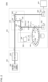
- Fig. 2 is a diagram illustrating an optical measurement apparatus 100A according to Embodiment 1.
- the optical measurement apparatus 100A has a light source apparatus 200, a spectroscopic head 300, and an arithmetic processing unit 400.
- the optical measurement apparatus 100A is directed to inspection of a product (sample 2) that is industrially mass-produced.
- the light source apparatus 200 generates the wavelength swept light L1 whose wavelength changes with time.
- the wavelength swept light L1 is featured by one-to-one correspondence between time and wavelength. This is expressed as the wavelength swept light L1 has "uniqueness of wavelength”.
- the light source apparatus 200 contains a pulsed light source 202 and a stretcher 210.
- the pulsed light source 202 emits broadband pulsed light L1a having a broadband continuous spectrum.
- the spectrum of the broadband pulsed light L1a is continuous typically within a wavelength range from 900 nm to 1300 nm, at least over a 10 nm range, preferably over a 50 nm range, and more preferably over a 100 nm range. Width of the wavelength range of the broadband pulsed light L1a may only be wide enough to cover a wavelength range necessary for the spectroscopy.
- Fig. 3 is a drawing illustrating the wavelength swept light L1.
- the upper tier of Fig. 3 illustrates intensity (time-axis waveform) I WS (t) of the wavelength swept light L1, and the lower tier illustrates a temporal change in wavelength ⁇ of the wavelength swept light L1.
- the wavelength swept light L1 in this example is given by a single pulse, having dominant wavelength ⁇ 1 at the leading edge, and dominant wavelength ⁇ n at the trailing edge, while demonstrating a temporal change in the wavelength between ⁇ 1 and ⁇ n within one pulse.
- the wavelength swept light L1 in this example is a positively chirped pulse ( ⁇ 1 > ⁇ n ) whose frequency increases with time, in other words, whose wavelength shortens with time.
- the wavelength swept light L1 may alternatively be a negatively chirped pulse whose wavelength becomes longer with time ( ⁇ 1 ⁇ ⁇ n ). As described later, the wavelength swept light L1 may be given by a pulse train that contains temporally isolated pulses (wave fluxes) for each wavelength.
- the spectroscopic head 300 contains an irradiation optical system 310, a light receiver 320, a conveyor 330, an optical path switching element 340, an aperture 342, and a controller 350.
- the irradiation optical system 310 receives the wavelength swept light L1 from the light source apparatus 200, and irradiates a measurement position where the target sample 2 to be measured should pass.
- the optical path switching element 340 in this embodiment is constituted as a part of the irradiation optical system 310, and the irradiation optical system 310 contains a beam splitter 314, mirrors 316, 318, and the optical path switching element 340.
- the irradiation optical system 310 may contain unillustrated mirror, lens, or the like.
- the optical path switching element 340 can be switched between a first state ⁇ 1 and a second state ⁇ 2, and can direct in the first state ⁇ 1 the wavelength swept light L1 to a first optical path OP1 laid through the measurement position 4, meanwhile can direct in the second state ⁇ 2 the light to a second optical path OP2 deviated from the first optical path OP1.
- a galvano mirror a micro electro-mechanical systems (MEMS) mirror, a polygon mirror, a piezo-driven mirror or the like, but not limited thereto.
- the aperture 342 is interposed between the optical path switching element 340 and the measurement position 4.
- the aperture 342 is an iris, a pinhole, a slit, a knife edge (single-edged slit) or the like, with which the first optical path OP1 is opened, meanwhile the light on the second optical path OP2 is shielded. Provision of the aperture 342 can prevent the wavelength swept light L1 from becoming stray light in the second state ⁇ 2.
- the light receiver 320 contains a first photodetector 322 and a second photodetector 324.
- the first photodetector 322 detects the object light L2 obtained by irradiating the wavelength swept light L1 onto the sample 2.
- the object light L2 in this embodiment is light ascribed to the wavelength swept light L1 transmitted through the sample 2.
- the second photodetector 324 detects the reference light L3. Output signals from the first photodetector 322 and the second photodetector 324 are respectively converted to digital signals D1 and D2 by an unillustrated A/D converter.
- a time-axis waveform I OBJ (t) of the object light L2 given by the digital signal D1, and a time-axis waveform I REF (t) of the reference light L3 given by the digital signal D2 are taken into an arithmetic processing unit 400.
- Fig. 4 is a drawing explaining spectroscopy with use of the optical measurement apparatus 100A illustrated in Fig. 2 . Since the wavelength swept light L1 is featured by the one-to-one correspondence between time t and wavelength ⁇ as described previously, so that the time-axis waveform I REF (t) may be converted to the spectrum I REF ( ⁇ ) in terms of frequency domain.
- the controller 350 monitors the conveyor 330, and determines presence or absence of the sample 2 in each sample holder 332.
- the controller 350 controls the optical path switching element 340, depending on presence or absence of the sample 2.
- the controller 350 contains a position sensor 352 and an arithmetic unit 356.
- the position sensor 352 is typically a rotary encoder, which detects the position (angle of rotation) of the conveyor 330.
- the arithmetic unit 356 preliminarily stores position information (load information) of the sample holder 332 not occupied by the sample 2.
- the load information is obtainable typically from a mounter that mounts the sample 2 on the sample holder 332, or from a host controller that controls the mounter. Alternatively, the load information may be manually entered by an operator who operates the optical measurement apparatus 100. Alternatively, in a case there is a preset inspection sequence by which a plurality of sample 2 are inspected in units (lots), wherein all sample holders 332 are occupied during the inspection for one lot, and will be vacant in an interval between the lots, absence of the sample 2 may be judged by the vacancy of the sample holders 332 in the interval between the lots.
- the arithmetic unit 356 compares the measurement value of the position sensor 352 with the load information that indicates the position of the sample holder 332 not occupied by the sample 2, and determines presence or absence of the sample at the measurement position 4.
- the arithmetic unit 356 controls the optical path switching element 340, according to the result of determination regarding presence or absence of the sample 2 at the measurement position 4.
- the arithmetic unit 356 keeps the optical path switching element 340 in the first state ⁇ 1, over a period the sample holder 332 occupied by the sample 2 passes through the measurement position 4. On the contrary, the arithmetic unit 356 switches the optical path switching element 340 to the second state ⁇ 2, over a period the sample holder 332 not occupied by the sample 2 passes through the measurement position 4.
- the optical path switching element 340 may be kept either in the first state ⁇ 1 or in the second state ⁇ 2, over a period the structure (disk) between the sample holders 332 passes through the measurement position 4. Basically, the sample holders 332 are more probable to have the sample 2 mounted thereon, whereas less probable to have no sample 2. Considering the service life of the optical path switching element 340, the optical path switching element 340 is preferably used while reducing the number of times of switching. The controller 350 therefore preferably keeps the optical path switching element 340 in the first state ⁇ 1, over a period the structure (disk) between the sample holders 332 passes through the measurement position 4.
- the optical path switching element 340 deviates the optical path of the wavelength swept light L1 from the normal optical path OP1, if the sample 2 is not present at the measurement position 4. This successfully prevents the high-power wavelength swept light L1, not attenuated by the sample 2, from being directly incident on the first photodetector 322, thereby protecting the first photodetector 322.
- the beam diameter of the wavelength swept light L1 in the wavelength swept light L1 was set to 0.8 mm (1/e 2 diameter).
- a slit with a 2 mm wide opening was used as the aperture 342.
- Retraction distance that is, the distance between the first optical path OP1 and the second optical path OP2 on the aperture 342 was set to 3 mm.
- Distance of retraction may be experimentally determined, in consideration of the damage threshold of the photodetector 322, the beam diameter, conveyance frequency, and performance (speed) of the optical path switching element 340.
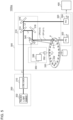
- Fig. 5 is a diagram illustrating an optical measurement apparatus 100Aa according to Modified Example 1.1.
- the aperture 342 illustrated in Fig. 2 is omitted.
- the second optical path OP2 over a period the optical path switching element 340 is kept in the second state ⁇ 2, is directed to a retreat position on the structure of the conveyor 330, while avoiding the areas of the sample holders 332.
- the other details are same as those illustrated in Fig. 2 .
- Fig. 6 is a diagram illustrating an optical measurement apparatus 100Ab according to Modified Example 1.2.
- the optical path switching element 340 illustrated in Fig. 2 was a part of the irradiation optical system 310, the optical path switching element 340 in this Modified Example 1.2 is positioned differently from that in Fig. 2 . More specifically, the optical path switching element 340 is arranged closer to the first photodetector 322 as viewed from the measurement position 4. The other details are same as those illustrated in Fig. 2 .
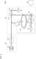
- Fig. 7 is a diagram illustrating an optical measurement apparatus 100Ac according to Modified Example 1.3.
- a conveyor 330c is structured differently from that in Fig. 2 .
- the conveyor 330c is similar to the conveyor 330 illustrated in Fig. 2 in that it has the rotating disk, but has no sample holder 332, instead having a vacuum suction mechanism that supports the sample 2 at any desired position on the circumference.
- the controller 350 compares the measurement value of the position sensor 352, with the position information of the sample holder not occupied by the sample, having been preliminarily stored in the arithmetic unit 356, and estimates whether the sample 2 is present or absent at the measurement position 4.
- the controller 350 switches the optical path switching element 340 to the first state ⁇ 1 over a period the sample 2 is present at the measurement position 4, meanwhile switches the optical path switching element 340 to the second state ⁇ 2 over a period the sample 2 is absent at the measurement position 4.
- the aperture 342 illustrated in Fig. 7 is omissible. Although the wavelength swept light L1 guided through the second optical path OP2 in this case can propagate without being blocked by the aperture 342, the purpose of protection of the first photodetector 322 may be fulfilled since the light is not incident on the first photodetector 322. The stray light, if anticipated, may be appropriately dealt with.
- the second optical path OP2 may be determined so as to be directed to the disk as illustrated in Fig. 5 .
- Fig. 8 is a diagram illustrating an optical measurement apparatus 100Ad according to Modified Example 1.4.
- An optical path switching element 340d in this Modified Example 1.4 is arranged between the light source apparatus 200 and the spectroscopic head 300.
- optical path switching element 340d is connected to the output-side fiber 258.
- the optical path switching element 340d is a fiber switch, whose one output is connected to the spectroscopic head 300 through the first optical path OP1, meanwhile the other output is directed to the second optical path OP2.
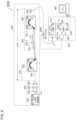
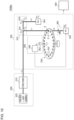
- Fig. 8 illustrates an exemplary specific structure of the light source apparatus 200.
- the light source apparatus 200 has a pulsed light source 202, a wavelength selector 220, and a stretcher 210.
- the pulsed light source 202 emits broadband pulsed light L1a having a broadband continuous spectrum.
- the spectrum of the broadband pulsed light L1a is continuous typically within a wavelength range from 900 nm to 1300 nm, at least over a 10 nm range, preferably over a 50 nm range, and more preferably over a 100 nm range. Width of the wavelength range of the broadband pulsed light L1a may only be wide enough to cover a wavelength range necessary for the spectroscopy.
- the pulsed light source 202 may contain an ultrashort pulse laser and a nonlinear element.
- the ultrashort pulse laser is exemplified by gain-switched laser, microchip laser, and fiber laser.
- the nonlinear element further widens the spectral width of the ultrashort pulse generated by the ultrashort pulse laser, with the aid of a nonlinear phenomenon.
- the nonlinear element is preferably a fiber, to which photonic crystal fiber or other nonlinear fiber is applicable. Mode of the fiber, although preferably single mode, may alternatively be multimode so long as a sufficient level of nonlinearity may be demonstrated.
- the pulsed light source 202 usable herein may be other broadband pulsed light source, such as superluminescent diode (SLD).
- SLD superluminescent diode
- the broadband pulsed light L1a output from the nonlinear element has a pulse width in the order of femtoseconds to nanoseconds.
- the broadband pulsed light L1a generated by the pulsed light source 202 is once emitted to a free space.
- the wavelength selector 220 selects a wavelength band to be used for the measurement from the broadband pulsed light L1a, and cuts off any wavelength band not to be used.
- the wavelength selector 220 contains a lens 222, a wavelength selection filter 224, and a condenser lens 226.
- the lens 222 collimates the broadband pulsed light L1a.
- the wavelength selection filter 224 allows a wavelength band to be used for the measurement to transmit therethrough, and cuts off any wavelength band no to be used by reflection or absorption.
- the condenser lens 226 condenses the light transmitted through the wavelength selection filter 224 onto the input end of a divider 230.
- the stretcher 210 receives the broadband pulsed light L1a, and convert the light into the wavelength swept light L1.
- the stretcher 210 contains the divider 230, a delay line 240, and a coupler 250.
- the divider 230 contains an input-side fiber 238 and a first AWG 232.
- the first AWG 232 has an input waveguide 234, and a plurality n (n ⁇ 2) of output waveguides 236.
- the first AWG 232 receives the broadband pulsed light L1a through the input-side fiber 238.
- the light guided through the input waveguide 234 is branched into n lines of the output waveguides 236, according to the wavelength.
- the delay line 240 contains a plurality n of fibers 242_1 to 242_n.
- the fibers 242_1 to 242_n have different lengths, and give different levels of delay to the multiple beams divided by the divider 230.
- the broadband pulsed light L1a before being divided is given by a positive chirp pulse (up-chirp pulse) whose frequency increases (wavelength shortens) with time.
- the pulse in this case contains a component having the longest wavelength ⁇ 1 at the leading edge, and a component having the shortest wavelength ⁇ n at the trailing edge.
- the plurality of fibers 242_1 to 242_n have different lengths I 1 to I n .
- ⁇ 1 denote the longest wavelength
- ⁇ n denote the shortest wavelength
- the lengths I 1 to I 20 of the twenty fibers 242 may increase from 1 m to 20 m in one-meter increments.
- the fibers 242_1 to 242_n do not necessarily have group delay characteristics which differ for each wavelength, and may use the same fiber (having the same core/clad material).
- the fiber 242 usable herein may be a multi-mode fiber, which is advantageous in that any unintended nonlinear optical effect is avoidable.
- the coupler 250 recombines a plurality of beams having been differently delayed by the delay line 240.
- the coupler 250 typically contains a second AWG 252 and the output-side fiber 258.
- the second AWG 252 has n lines of input waveguides 254, and an output waveguide 256.
- the n lines of input waveguides 254 have the n fibers 242_1 to 242_n connected thereto.
- the second AWG 252 multiplexes n beams guided through the n lines of input waveguides 254, and outputs the resultant beam to the output waveguide 256.
- the input end of the output-side fiber 258 is connected to the output waveguide 256.
- the output-side fiber 258 extends to the spectroscopic head 300, and the output end of the output-side fiber 258 is connected to the spectroscopic head 300.
- the individual wave fluxes having the wavelengths ⁇ 1 to ⁇ n are temporally separated, thus converting the wavelength swept light L1 to a pulse train that contains n pulses corresponded to the wavelengths ⁇ 1 to ⁇ n .
- the spectroscopic head 300 contains the controller 350.
- the controller 350 compares the measurement value of the position sensor 352, with the position information of the sample holder not occupied by the sample, having been preliminarily stored in the arithmetic unit 356, to determine whether the sample 2 is present or absent, and controls the optical path switching element 340d with reference to the result of determination.
- Fig. 9 is a drawing illustrating an optical measurement apparatus 100B according to Embodiment 2.
- the optical measurement apparatus 100B contains a light shielding element 360, in place of the optical path switching element 340 illustrated in Fig. 2 .
- the light shielding element 360 is arranged on the optical path of the wavelength swept light L1, and is structured to be switchable between the first state ⁇ 1 and the second state ⁇ 2.
- the light shielding element 360 allows the wavelength swept light L1 to pass therethrough in the first state ⁇ 1 (transmission state), and shields the object light L2 in the second state ⁇ 2.
- Light shielding also includes dimming.
- variable attenuator is exemplified by liquid crystal shutter, acousto-optical modulator (AOM), and electro-optical modulator (EOM).
- the controller 350 controls the state of the light shielding element 360.
- the control by the controller 350 is similar to that in Embodiment 1.
- the light shielding element 360 shields the optical path of the wavelength swept light L1, if the sample 2 is absent at the measurement position 4. This successfully prevents the high-power wavelength swept light L1, not attenuated by the sample 2, from being directly incident on the first photodetector 322, thereby protecting the first photodetector 322.
- Fig. 10 is a diagram illustrating an optical measurement apparatus 100Ba according to Modified Example 2.1.
- the light shielding element 360 is arranged on the path of the wavelength swept light L1, closer to the first photodetector 322 as viewed from the measurement position 4.
- the conveyor 330c illustrated in Fig. 7 may be applied to Embodiment 2.
- the light shielding element 360 may be arranged between the light source apparatus 200 and the spectroscopic head 300, like in the case illustrated in Fig. 8 .
- the conveyor 330 is not limited to a disk-shaped one.
- a roller conveyor may be used for example.
Landscapes
- Physics & Mathematics (AREA)
- Spectroscopy & Molecular Physics (AREA)
- General Physics & Mathematics (AREA)
- Chemical & Material Sciences (AREA)
- Life Sciences & Earth Sciences (AREA)
- Analytical Chemistry (AREA)
- Biochemistry (AREA)
- General Health & Medical Sciences (AREA)
- Health & Medical Sciences (AREA)
- Immunology (AREA)
- Pathology (AREA)
- Optics & Photonics (AREA)
- Engineering & Computer Science (AREA)
- Textile Engineering (AREA)
- Investigating Or Analysing Materials By Optical Means (AREA)
- Spectrometry And Color Measurement (AREA)
Applications Claiming Priority (2)
| Application Number | Priority Date | Filing Date | Title |
|---|---|---|---|
| JP2022092376A JP2023179208A (ja) | 2022-06-07 | 2022-06-07 | 光測定装置 |
| PCT/JP2023/019148 WO2023238654A1 (ja) | 2022-06-07 | 2023-05-23 | 光測定装置 |
Publications (2)
| Publication Number | Publication Date |
|---|---|
| EP4521082A1 true EP4521082A1 (de) | 2025-03-12 |
| EP4521082A4 EP4521082A4 (de) | 2026-04-29 |
Family
ID=89118187
Family Applications (1)
| Application Number | Title | Priority Date | Filing Date |
|---|---|---|---|
| EP23819638.0A Pending EP4521082A4 (de) | 2022-06-07 | 2023-05-23 | Optische messeinrichtung |
Country Status (6)
| Country | Link |
|---|---|
| US (1) | US20250354916A1 (de) |
| EP (1) | EP4521082A4 (de) |
| JP (1) | JP2023179208A (de) |
| KR (1) | KR20240161191A (de) |
| CN (1) | CN119072614A (de) |
| WO (1) | WO2023238654A1 (de) |
Families Citing this family (1)
| Publication number | Priority date | Publication date | Assignee | Title |
|---|---|---|---|---|
| JP2025017664A (ja) * | 2023-07-25 | 2025-02-06 | 第一実業ビスウィル株式会社 | 光測定装置 |
Family Cites Families (16)
| Publication number | Priority date | Publication date | Assignee | Title |
|---|---|---|---|---|
| JPS6295448A (ja) * | 1985-10-23 | 1987-05-01 | Kowa Co | 粒子測定方法及び装置 |
| JPH0979978A (ja) * | 1995-09-11 | 1997-03-28 | Ishikawajima Harima Heavy Ind Co Ltd | 菜果の非破壊式成分計測装置 |
| JP2782331B2 (ja) * | 1995-09-12 | 1998-07-30 | 東洋農機株式会社 | 根菜類検出装置 |
| US5995867A (en) * | 1997-03-19 | 1999-11-30 | Lucid Inc | Cellular surgery utilizing confocal microscopy |
| JPH1151928A (ja) * | 1997-08-06 | 1999-02-26 | Kubota Corp | 青果物の品質計測装置 |
| US6876392B1 (en) * | 1998-12-22 | 2005-04-05 | Matsushita Electric Industrial Co., Ltd. | Rangefinder for obtaining information from a three-dimensional object |
| KR100691924B1 (ko) * | 1999-04-27 | 2007-03-09 | 지에스아이 루모닉스 인코퍼레이티드 | 재료 가공 장치 및 방법 |
| JP2004089397A (ja) * | 2002-08-30 | 2004-03-25 | Nidek Co Ltd | レーザ治療装置 |
| US7409117B2 (en) * | 2004-02-11 | 2008-08-05 | American Air Liquide, Inc. | Dynamic laser power control for gas species monitoring |
| GB0415292D0 (en) * | 2004-07-08 | 2004-08-11 | Qinetiq Ltd | Optical fibre alignment apparatus and method |
| JP4677367B2 (ja) * | 2006-06-05 | 2011-04-27 | オリンパス株式会社 | 照明装置、及び顕微鏡システム |
| JP2011147966A (ja) * | 2010-01-21 | 2011-08-04 | Sumitomo Electric Ind Ltd | レーザ加工装置及びその加工方法 |
| TWI576570B (zh) * | 2012-06-22 | 2017-04-01 | 維克儀器公司 | 用於輻射測溫計之遠心光學裝置、使用遠心鏡片配置以減少輻射測溫計中雜散輻射之方法及溫度測量系統 |
| CN108401442B (zh) * | 2015-06-30 | 2021-01-15 | 伊利诺斯工具制品有限公司 | 联机x射线测量设备和方法 |
| JP7115387B2 (ja) | 2019-03-27 | 2022-08-09 | ウシオ電機株式会社 | 光測定用光源装置、分光測定装置及び分光測定方法 |
| US11231316B2 (en) * | 2019-12-04 | 2022-01-25 | Lockheed Martin Corporation | Sectional optical block |
-
2022
- 2022-06-07 JP JP2022092376A patent/JP2023179208A/ja active Pending
-
2023
- 2023-05-23 CN CN202380035265.2A patent/CN119072614A/zh active Pending
- 2023-05-23 WO PCT/JP2023/019148 patent/WO2023238654A1/ja not_active Ceased
- 2023-05-23 US US18/871,760 patent/US20250354916A1/en active Pending
- 2023-05-23 KR KR1020247035149A patent/KR20240161191A/ko active Pending
- 2023-05-23 EP EP23819638.0A patent/EP4521082A4/de active Pending
Also Published As
| Publication number | Publication date |
|---|---|
| JP2023179208A (ja) | 2023-12-19 |
| CN119072614A (zh) | 2024-12-03 |
| EP4521082A4 (de) | 2026-04-29 |
| WO2023238654A1 (ja) | 2023-12-14 |
| US20250354916A1 (en) | 2025-11-20 |
| KR20240161191A (ko) | 2024-11-12 |
Similar Documents
| Publication | Publication Date | Title |
|---|---|---|
| US12359971B2 (en) | Spectral measurement method, spectral measurement system, and broadband pulsed light source unit | |
| EP2031374B1 (de) | Vorrichtung und Verfahren zur Gewinnung von Informationen im Zusammenhang mit Terahertz-Wellen | |
| US9702975B2 (en) | Lidar measuring system and lidar measuring method | |
| US10866319B2 (en) | Stray-light tolerant lidar measurement system and stray-light tolerant lidar measurement method | |
| US6865014B2 (en) | Apparatus and method for investigating a sample | |
| US9170410B2 (en) | Apparatus for temporal displacement of white light laser pulses | |
| EP4001868A1 (de) | Vorrichtung und verfahren zur messung der reflektivität oder transmissivität einer optischen oberfläche | |
| EP4521082A1 (de) | Optische messeinrichtung | |
| EP2559992A1 (de) | System zur Blitzlichtphotolyse | |
| US20080265165A1 (en) | Phase-matched terahertz emitter | |
| US6204926B1 (en) | Methods and system for optically correlating ultrashort optical waveforms | |
| WO2020196692A1 (ja) | 広帯域パルス光源装置、分光測定装置及び分光測定方法 | |
| US20180080868A1 (en) | Terahertz wave measuring device | |
| EP0758082B1 (de) | Vorrichtung zur Messung interner Information in streuenden Medien | |
| KR960019498A (ko) | 인프로세스막두께모니터장치 및 방법 | |
| JP2012132704A (ja) | ピークパワーモニター装置、およびピークパワーのモニター方法 | |
| US12523596B2 (en) | Light source apparatus | |
| JP2017044551A (ja) | 自己相関測定装置 | |
| EP4414687A1 (de) | Optisches messverfahren und optische messvorrichtung | |
| CN212844017U (zh) | 一种新型激光脉冲自相关仪 | |
| JP2020159977A (ja) | 広帯域パルス光源装置、分光測定装置及び分光測定方法 | |
| WO2025022803A1 (ja) | 光測定装置 | |
| EP3333567A1 (de) | Verfahren und vorrichtung zur messung der kollimierten transmittanz eines halbtransparenten körpers | |
| JP2005241284A (ja) | 波長分散測定装置及び測定方法 | |
| NL8401284A (nl) | Optische verplaatsingsaftastinrichting. |
Legal Events
| Date | Code | Title | Description |
|---|---|---|---|
| STAA | Information on the status of an ep patent application or granted ep patent |
Free format text: STATUS: THE INTERNATIONAL PUBLICATION HAS BEEN MADE |
|
| PUAI | Public reference made under article 153(3) epc to a published international application that has entered the european phase |
Free format text: ORIGINAL CODE: 0009012 |
|
| STAA | Information on the status of an ep patent application or granted ep patent |
Free format text: STATUS: REQUEST FOR EXAMINATION WAS MADE |
|
| 17P | Request for examination filed |
Effective date: 20241205 |
|
| AK | Designated contracting states |
Kind code of ref document: A1 Designated state(s): AL AT BE BG CH CY CZ DE DK EE ES FI FR GB GR HR HU IE IS IT LI LT LU LV MC ME MK MT NL NO PL PT RO RS SE SI SK SM TR |
|
| DAV | Request for validation of the european patent (deleted) | ||
| DAX | Request for extension of the european patent (deleted) | ||
| RAP3 | Party data changed (applicant data changed or rights of an application transferred) |
Owner name: USHIO DENKI KABUSHIKI KAISHA |