EP4520368A2 - Autoinjektor - Google Patents
Autoinjektor Download PDFInfo
- Publication number
- EP4520368A2 EP4520368A2 EP25153104.2A EP25153104A EP4520368A2 EP 4520368 A2 EP4520368 A2 EP 4520368A2 EP 25153104 A EP25153104 A EP 25153104A EP 4520368 A2 EP4520368 A2 EP 4520368A2
- Authority
- EP
- European Patent Office
- Prior art keywords
- syringe
- plunger
- auto
- injector
- barrel
- Prior art date
- Legal status (The legal status is an assumption and is not a legal conclusion. Google has not performed a legal analysis and makes no representation as to the accuracy of the status listed.)
- Pending
Links
Images


Classifications
-
- A—HUMAN NECESSITIES
- A61—MEDICAL OR VETERINARY SCIENCE; HYGIENE
- A61M—DEVICES FOR INTRODUCING MEDIA INTO, OR ONTO, THE BODY; DEVICES FOR TRANSDUCING BODY MEDIA OR FOR TAKING MEDIA FROM THE BODY; DEVICES FOR PRODUCING OR ENDING SLEEP OR STUPOR
- A61M5/00—Devices for bringing media into the body in a subcutaneous, intra-vascular or intramuscular way; Accessories therefor, e.g. filling or cleaning devices, arm-rests
- A61M5/002—Packages specially adapted therefor, e.g. for syringes or needles, kits for diabetics
-
- A—HUMAN NECESSITIES
- A61—MEDICAL OR VETERINARY SCIENCE; HYGIENE
- A61M—DEVICES FOR INTRODUCING MEDIA INTO, OR ONTO, THE BODY; DEVICES FOR TRANSDUCING BODY MEDIA OR FOR TAKING MEDIA FROM THE BODY; DEVICES FOR PRODUCING OR ENDING SLEEP OR STUPOR
- A61M5/00—Devices for bringing media into the body in a subcutaneous, intra-vascular or intramuscular way; Accessories therefor, e.g. filling or cleaning devices, arm-rests
- A61M5/178—Syringes
- A61M5/20—Automatic syringes, e.g. with automatically actuated piston rod, with automatic needle injection, filling automatically
-
- A—HUMAN NECESSITIES
- A61—MEDICAL OR VETERINARY SCIENCE; HYGIENE
- A61M—DEVICES FOR INTRODUCING MEDIA INTO, OR ONTO, THE BODY; DEVICES FOR TRANSDUCING BODY MEDIA OR FOR TAKING MEDIA FROM THE BODY; DEVICES FOR PRODUCING OR ENDING SLEEP OR STUPOR
- A61M5/00—Devices for bringing media into the body in a subcutaneous, intra-vascular or intramuscular way; Accessories therefor, e.g. filling or cleaning devices, arm-rests
- A61M5/178—Syringes
- A61M5/20—Automatic syringes, e.g. with automatically actuated piston rod, with automatic needle injection, filling automatically
- A61M5/2033—Spring-loaded one-shot injectors with or without automatic needle insertion
-
- A—HUMAN NECESSITIES
- A61—MEDICAL OR VETERINARY SCIENCE; HYGIENE
- A61M—DEVICES FOR INTRODUCING MEDIA INTO, OR ONTO, THE BODY; DEVICES FOR TRANSDUCING BODY MEDIA OR FOR TAKING MEDIA FROM THE BODY; DEVICES FOR PRODUCING OR ENDING SLEEP OR STUPOR
- A61M5/00—Devices for bringing media into the body in a subcutaneous, intra-vascular or intramuscular way; Accessories therefor, e.g. filling or cleaning devices, arm-rests
- A61M5/178—Syringes
- A61M5/24—Ampoule syringes, i.e. syringes with needle for use in combination with replaceable ampoules or carpules, e.g. automatic
-
- A—HUMAN NECESSITIES
- A61—MEDICAL OR VETERINARY SCIENCE; HYGIENE
- A61M—DEVICES FOR INTRODUCING MEDIA INTO, OR ONTO, THE BODY; DEVICES FOR TRANSDUCING BODY MEDIA OR FOR TAKING MEDIA FROM THE BODY; DEVICES FOR PRODUCING OR ENDING SLEEP OR STUPOR
- A61M5/00—Devices for bringing media into the body in a subcutaneous, intra-vascular or intramuscular way; Accessories therefor, e.g. filling or cleaning devices, arm-rests
- A61M5/178—Syringes
- A61M5/31—Details
- A61M5/315—Pistons; Piston-rods; Guiding, blocking or restricting the movement of the rod or piston; Appliances on the rod for facilitating dosing ; Dosing mechanisms
- A61M5/31565—Administration mechanisms, i.e. constructional features, modes of administering a dose
- A61M5/31566—Means improving security or handling thereof
- A61M5/3157—Means providing feedback signals when administration is completed
-
- A—HUMAN NECESSITIES
- A61—MEDICAL OR VETERINARY SCIENCE; HYGIENE
- A61M—DEVICES FOR INTRODUCING MEDIA INTO, OR ONTO, THE BODY; DEVICES FOR TRANSDUCING BODY MEDIA OR FOR TAKING MEDIA FROM THE BODY; DEVICES FOR PRODUCING OR ENDING SLEEP OR STUPOR
- A61M5/00—Devices for bringing media into the body in a subcutaneous, intra-vascular or intramuscular way; Accessories therefor, e.g. filling or cleaning devices, arm-rests
- A61M5/178—Syringes
- A61M5/31—Details
- A61M5/32—Needles; Details of needles pertaining to their connection with syringe or hub; Accessories for bringing the needle into, or holding the needle on, the body; Devices for protection of needles
- A61M5/3202—Devices for protection of the needle before use, e.g. caps
-
- A—HUMAN NECESSITIES
- A61—MEDICAL OR VETERINARY SCIENCE; HYGIENE
- A61M—DEVICES FOR INTRODUCING MEDIA INTO, OR ONTO, THE BODY; DEVICES FOR TRANSDUCING BODY MEDIA OR FOR TAKING MEDIA FROM THE BODY; DEVICES FOR PRODUCING OR ENDING SLEEP OR STUPOR
- A61M5/00—Devices for bringing media into the body in a subcutaneous, intra-vascular or intramuscular way; Accessories therefor, e.g. filling or cleaning devices, arm-rests
- A61M5/46—Devices for bringing media into the body in a subcutaneous, intra-vascular or intramuscular way; Accessories therefor, e.g. filling or cleaning devices, arm-rests having means for controlling depth of insertion
-
- A—HUMAN NECESSITIES
- A61—MEDICAL OR VETERINARY SCIENCE; HYGIENE
- A61M—DEVICES FOR INTRODUCING MEDIA INTO, OR ONTO, THE BODY; DEVICES FOR TRANSDUCING BODY MEDIA OR FOR TAKING MEDIA FROM THE BODY; DEVICES FOR PRODUCING OR ENDING SLEEP OR STUPOR
- A61M5/00—Devices for bringing media into the body in a subcutaneous, intra-vascular or intramuscular way; Accessories therefor, e.g. filling or cleaning devices, arm-rests
- A61M5/178—Syringes
- A61M5/20—Automatic syringes, e.g. with automatically actuated piston rod, with automatic needle injection, filling automatically
- A61M2005/2006—Having specific accessories
- A61M2005/2013—Having specific accessories triggering of discharging means by contact of injector with patient body
-
- A—HUMAN NECESSITIES
- A61—MEDICAL OR VETERINARY SCIENCE; HYGIENE
- A61M—DEVICES FOR INTRODUCING MEDIA INTO, OR ONTO, THE BODY; DEVICES FOR TRANSDUCING BODY MEDIA OR FOR TAKING MEDIA FROM THE BODY; DEVICES FOR PRODUCING OR ENDING SLEEP OR STUPOR
- A61M5/00—Devices for bringing media into the body in a subcutaneous, intra-vascular or intramuscular way; Accessories therefor, e.g. filling or cleaning devices, arm-rests
- A61M5/178—Syringes
- A61M5/31—Details
- A61M5/315—Pistons; Piston-rods; Guiding, blocking or restricting the movement of the rod or piston; Appliances on the rod for facilitating dosing ; Dosing mechanisms
- A61M5/31511—Piston or piston-rod constructions, e.g. connection of piston with piston-rod
- A61M2005/31518—Piston or piston-rod constructions, e.g. connection of piston with piston-rod designed to reduce the overall size of an injection device, e.g. using flexible or pivotally connected chain-like rod members
-
- A—HUMAN NECESSITIES
- A61—MEDICAL OR VETERINARY SCIENCE; HYGIENE
- A61M—DEVICES FOR INTRODUCING MEDIA INTO, OR ONTO, THE BODY; DEVICES FOR TRANSDUCING BODY MEDIA OR FOR TAKING MEDIA FROM THE BODY; DEVICES FOR PRODUCING OR ENDING SLEEP OR STUPOR
- A61M5/00—Devices for bringing media into the body in a subcutaneous, intra-vascular or intramuscular way; Accessories therefor, e.g. filling or cleaning devices, arm-rests
- A61M5/178—Syringes
- A61M5/31—Details
- A61M5/32—Needles; Details of needles pertaining to their connection with syringe or hub; Accessories for bringing the needle into, or holding the needle on, the body; Devices for protection of needles
- A61M5/3205—Apparatus for removing or disposing of used needles or syringes, e.g. containers; Means for protection against accidental injuries from used needles
- A61M5/321—Means for protection against accidental injuries by used needles
- A61M5/3243—Means for protection against accidental injuries by used needles being axially-extensible, e.g. protective sleeves coaxially slidable on the syringe barrel
- A61M5/326—Fully automatic sleeve extension, i.e. in which triggering of the sleeve does not require a deliberate action by the user
- A61M2005/3267—Biased sleeves where the needle is uncovered by insertion of the needle into a patient's body
-
- A—HUMAN NECESSITIES
- A61—MEDICAL OR VETERINARY SCIENCE; HYGIENE
- A61M—DEVICES FOR INTRODUCING MEDIA INTO, OR ONTO, THE BODY; DEVICES FOR TRANSDUCING BODY MEDIA OR FOR TAKING MEDIA FROM THE BODY; DEVICES FOR PRODUCING OR ENDING SLEEP OR STUPOR
- A61M2205/00—General characteristics of the apparatus
- A61M2205/14—Detection of the presence or absence of a tube, a connector or a container in an apparatus
-
- A—HUMAN NECESSITIES
- A61—MEDICAL OR VETERINARY SCIENCE; HYGIENE
- A61M—DEVICES FOR INTRODUCING MEDIA INTO, OR ONTO, THE BODY; DEVICES FOR TRANSDUCING BODY MEDIA OR FOR TAKING MEDIA FROM THE BODY; DEVICES FOR PRODUCING OR ENDING SLEEP OR STUPOR
- A61M2205/00—General characteristics of the apparatus
- A61M2205/35—Communication
- A61M2205/3546—Range
- A61M2205/3561—Range local, e.g. within room or hospital
-
- A—HUMAN NECESSITIES
- A61—MEDICAL OR VETERINARY SCIENCE; HYGIENE
- A61M—DEVICES FOR INTRODUCING MEDIA INTO, OR ONTO, THE BODY; DEVICES FOR TRANSDUCING BODY MEDIA OR FOR TAKING MEDIA FROM THE BODY; DEVICES FOR PRODUCING OR ENDING SLEEP OR STUPOR
- A61M2205/00—General characteristics of the apparatus
- A61M2205/35—Communication
- A61M2205/3546—Range
- A61M2205/3569—Range sublocal, e.g. between console and disposable
-
- A—HUMAN NECESSITIES
- A61—MEDICAL OR VETERINARY SCIENCE; HYGIENE
- A61M—DEVICES FOR INTRODUCING MEDIA INTO, OR ONTO, THE BODY; DEVICES FOR TRANSDUCING BODY MEDIA OR FOR TAKING MEDIA FROM THE BODY; DEVICES FOR PRODUCING OR ENDING SLEEP OR STUPOR
- A61M2205/00—General characteristics of the apparatus
- A61M2205/35—Communication
- A61M2205/3576—Communication with non implanted data transmission devices, e.g. using external transmitter or receiver
- A61M2205/3584—Communication with non implanted data transmission devices, e.g. using external transmitter or receiver using modem, internet or Bluetooth®
-
- A—HUMAN NECESSITIES
- A61—MEDICAL OR VETERINARY SCIENCE; HYGIENE
- A61M—DEVICES FOR INTRODUCING MEDIA INTO, OR ONTO, THE BODY; DEVICES FOR TRANSDUCING BODY MEDIA OR FOR TAKING MEDIA FROM THE BODY; DEVICES FOR PRODUCING OR ENDING SLEEP OR STUPOR
- A61M2205/00—General characteristics of the apparatus
- A61M2205/50—General characteristics of the apparatus with microprocessors or computers
-
- A—HUMAN NECESSITIES
- A61—MEDICAL OR VETERINARY SCIENCE; HYGIENE
- A61M—DEVICES FOR INTRODUCING MEDIA INTO, OR ONTO, THE BODY; DEVICES FOR TRANSDUCING BODY MEDIA OR FOR TAKING MEDIA FROM THE BODY; DEVICES FOR PRODUCING OR ENDING SLEEP OR STUPOR
- A61M2205/00—General characteristics of the apparatus
- A61M2205/50—General characteristics of the apparatus with microprocessors or computers
- A61M2205/52—General characteristics of the apparatus with microprocessors or computers with memories providing a history of measured variating parameters of apparatus or patient
-
- A—HUMAN NECESSITIES
- A61—MEDICAL OR VETERINARY SCIENCE; HYGIENE
- A61M—DEVICES FOR INTRODUCING MEDIA INTO, OR ONTO, THE BODY; DEVICES FOR TRANSDUCING BODY MEDIA OR FOR TAKING MEDIA FROM THE BODY; DEVICES FOR PRODUCING OR ENDING SLEEP OR STUPOR
- A61M2205/00—General characteristics of the apparatus
- A61M2205/58—Means for facilitating use, e.g. by people with impaired vision
- A61M2205/581—Means for facilitating use, e.g. by people with impaired vision by audible feedback
-
- A—HUMAN NECESSITIES
- A61—MEDICAL OR VETERINARY SCIENCE; HYGIENE
- A61M—DEVICES FOR INTRODUCING MEDIA INTO, OR ONTO, THE BODY; DEVICES FOR TRANSDUCING BODY MEDIA OR FOR TAKING MEDIA FROM THE BODY; DEVICES FOR PRODUCING OR ENDING SLEEP OR STUPOR
- A61M2205/00—General characteristics of the apparatus
- A61M2205/58—Means for facilitating use, e.g. by people with impaired vision
- A61M2205/583—Means for facilitating use, e.g. by people with impaired vision by visual feedback
-
- A—HUMAN NECESSITIES
- A61—MEDICAL OR VETERINARY SCIENCE; HYGIENE
- A61M—DEVICES FOR INTRODUCING MEDIA INTO, OR ONTO, THE BODY; DEVICES FOR TRANSDUCING BODY MEDIA OR FOR TAKING MEDIA FROM THE BODY; DEVICES FOR PRODUCING OR ENDING SLEEP OR STUPOR
- A61M2205/00—General characteristics of the apparatus
- A61M2205/58—Means for facilitating use, e.g. by people with impaired vision
- A61M2205/587—Lighting arrangements
-
- A—HUMAN NECESSITIES
- A61—MEDICAL OR VETERINARY SCIENCE; HYGIENE
- A61M—DEVICES FOR INTRODUCING MEDIA INTO, OR ONTO, THE BODY; DEVICES FOR TRANSDUCING BODY MEDIA OR FOR TAKING MEDIA FROM THE BODY; DEVICES FOR PRODUCING OR ENDING SLEEP OR STUPOR
- A61M2205/00—General characteristics of the apparatus
- A61M2205/60—General characteristics of the apparatus with identification means
- A61M2205/6054—Magnetic identification systems
Definitions
- the invention relates to auto-injectors for use with syringes.
- the invention may relate to, but need not be limited to, safety auto-injectors and/or auto-injectors for use with safety syringes.
- Safety syringes typically include some form of safety mechanism to protect healthcare workers from a hypodermic needle of the syringe after it has been injected into a patient.
- Exemplary safety syringes may include a shroud or sheath for covering the needle after use of the syringe.
- Other exemplary syringes may cause the needle to retract within the barrel of the syringe.
- Safety syringes may be broadly split into 'active' and 'passive' safety syringes. Active safety syringes typically require some action by a user of the syringe to engage the safety mechanism. Such action may be taken after removal of the needle from the patient, or may be taken during removal of the needle from the patient. Passive safety syringes typically engage the safety mechanism without any specific action by the user, that is, without any action other than that usually taken to use the syringe.
- An auto-injector is a device for receiving a syringe and for driving a syringe plunger of the syringe into a barrel of the syringe, typically without any driving force being applied by the user, although some force may be required for activation.
- an auto-injector includes a plunger driver, such as a spring, that is arranged to provide a force to drive the syringe plunger into the barrel.
- the plunger driver is typically activated by operation of a button or other release mechanism on the auto-injector.
- a safety auto-injector may be one which includes a shroud that may be deployed to a position covering a needle of a syringe received within the auto-injector after use of the auto-injector.
- the shroud of the auto-injector may be deployed under a force applied by a shroud driver.
- the first detector is configured to be operable in dependence on the second detector having detected such engagement.
- the auto-injector further comprises a third detector configured to detect the presence of the safety syringe.
- the first detector is configured to be operable in dependence on the third detector having detected the presence of the safety syringe.
- an auto-injector for use with a safety syringe, the auto-injector comprising: a main body that is openable for receiving the safety syringe and closable before operation of the auto-injector; a first detector configured, after activation of the auto-injector, to detect movement of a plunger of the safety syringe to a point on a delivery stroke thereof that is indicative of full dose delivery of a substance from the safety syringe; a second detector configured to detect that the housing is in a closed position; and a third detector configured to detect a presence of the safety syringe, wherein the first detector is configured to be operable in dependence of at least one of the second detector having detected engagement between the barrel portion and the plunger portion and the third detector having detected the presence of the safety syringe.
- the main body comprises a hinged door openable for receiving the safety syringe and closable before operation of the auto-injector.
- the main body comprises: a barrel portion configured to receive a barrel of the safety syringe; and a plunger portion configured to receive a plunger of the safety syringe, wherein the barrel portion and the plunger portion are configured for detachable engagement, and wherein the main body is in the open position when the plunger portion and the barrel portion are detached.
- the first detector comprises a switch, and optionally a micro-switch, operable by a part of the safety syringe during the delivery stroke of the plunger of the safety syringe.
- the switch is operable by the syringe plunger at the point on the delivery stroke.
- the point on the delivery stroke is reached before completion of the delivery stroke.
- a distance between the point on the delivery stroke and the point of completion of the delivery stroke is sufficient to account for manufacturing tolerances in the safety syringe.
- the auto-injector further comprises one or more indicators configured based on data received from the first detector to indicate whether the full dose was delivered.
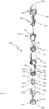
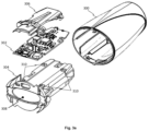
- the barrel portion 102 and the plunger portion 104 may be disconnected to allow the insertion of a syringe 200 into the auto-injector 100 and reconnected once the syringe 200 has been inserted. Further, when a syringe 200 is fitted within the auto-injector 100, rotation of the plunger portion 104 with respect to the barrel portion 102 rotates the syringe 200 such that a part of the syringe 200 rides over a cam surface to translate the rotational movement of the syringe to linear movement, which acts to decouple the syringe from the barrel portion 102. Alternatively, rotation of the syringe 200 by rotation of the plunger portion 104 deforms the coupling members retaining the syringe 200 within the barrel portion 102 such that the syringe is decoupled from the barrel portion 102.
- the RNS remover 106 further comprises prongs 118a, 118b.
- the prongs 118a-b are configured to be received within the barrel portion 102 when the RNS remover 106 is connected to the barrel portion 102.
- the prongs 118a, 118b comprise a spring compression surface that is configured to couple to the compression spring 134 when the RNS remover 106 is reconnected to the auto-injector 100 for priming the compression spring 134.
- exemplary auto-injectors are configured for use with the safety syringe 200.
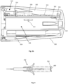
- the exemplary syringe 200 shown in Figures 2a and 2b is fitted within the auto-injector 100 and is a safety syringe.
- a plunger 206 is a safety plunger coupled to a sheath 216 and comprises a plunger head 204 and two arms 212a, 212b extending from opposed sides of the plunger head 204.
- the arms 212a, 212b connect the plunger head 206 to the sheath 216.
- the arms 212a, 212b are slidable along the outside of the barrel 214 such that the sheath 216 moves along the outside of the barrel 214 on application of a force to the plunger head 204.
- the arms 212a, 212b of the safety plunger 200 pass through the handle portion 218 such that the safety plunger 206 may move along its stroke relative to the handle portion 218 and, therefore, the barrel 214.
- the sheath 216 is configured to travel along the outside of the barrel 214 with the inward stroke of the safety plunger 206 until the sheath 216 at least partially covers a needle of the safety syringe 200. At the innermost point of the stroke of the safety plunger 206, the end of the sheath 216 is beyond the end of the needle, such that the sharp point of the needle is not exposed.
- the safety plunger 206 is coupled to a syringe plunger 222 during a first part of its inward stroke and so the syringe plunger 222 is driven into the barrel 214 on movement of the safety plunger 206 along its inward stroke.
- the safety plunger 206 decouples from the syringe plunger 222 at a point on the inward stroke, which may be when the syringe plunger 222 has expelled all of a medicament or drug from the barrel 214.
- the safety plunger 206 may move longitudinally relative to the syringe plunger 222 and continued movement of the safety plunger 206 moves the sheath 214 into a position covering the needle.
- decoupling may refer to longitudinal decoupling. There may exist a rotational coupling of the safety plunger 206 and the syringe plunger 222 after longitudinal decoupling.
- the safety syringe 200 may comprise a rate controlling means for controlling a rate of travel of the safety plunger 206 after decoupling.
- the rate controlling means may comprise a rate limiting member coupled to the safety plunger 206 and configured to engage with the syringe plunger 222.
- the rate limiting member may comprise a first screw thread 224 and the syringe plunger 222 may comprise a second screw thread that is configured to engage with the first screw thread 224 to rotate the syringe plunger 222 on linear movement of the safety plunger 206 after decoupling.
- the decoupling mechanism may comprise a rotation prevention member configured to prevent rotation of the syringe plunger 222 before decoupling.
- the rotation prevention member may comprise an aperture through which the syringe plunger 222 passes, wherein the aperture comprises first keying features configured to correspond to second keying features on the syringe plunger 222 such that the syringe plunger 222 is prevented from rotating.
- the syringe plunger 222 may be configured such that the second keying features disengage from the first keying features to decouple the syringe plunger 222 from the safety plunger 206.
- the syringe plunger 222 may be configured to pass through the aperture completely to linearly decouple the syringe plunger 222 from the safety plunger 206.
- the contact actuator 110 comprises castellation channels 124a-c. Three castellation channels 124a-c are visible in Figure 2b , however exemplary auto-injectors may comprise any number of castellation channels 124a-c.
- the castellation channels 124a-c extend longitudinally (with respect to the auto-injector) from the needle end of the contact actuator 110.
- the castellation channels 124a-c are different lengths.
- Each castellation channel 124a-c comprises a mechanical end stop surface at a plunger end of the castellation channel 124a-c. Because the castellation channels 124a-c are of different lengths, each mechanical end stop surface is located at a different distance longitudinally from the needle end of the contact actuator 110.
- the castellation channels 124a-c are configured to receive the protrusion 122 of the depth adjustor 108.
- the depth adjustor 108 is rotatable within the contact actuator 110 to allow the protrusion 122 to align with the desired castellation channel 124a-c.
- the castellation channels 124a-c may be configured to allow the protrusion 122 to travel within one of the castellation channels 124a-c.
- the castellation channels 124a-c may be of substantially the same width as the protrusion 122 such that when the protrusion 122 enters one of the castellation channels 124a-c, rotation of the depth adjustor 108 is prevented and only longitudinal movement of the depth adjustor 108 is possible.
- the compression spring 134 is received within the clips 138a, 138b such that one end of the compression spring 134 abuts the base 142a, 142b of the clips 138a, 138b and the resiliently deformable members 140a, 140b extend either side of the compression spring 134.
- the third micro-switch may be suitably positioned within the main body or on the hinged door such that the third micro-switch is operated when the syringe is inserted within the main body.
- the plunger portion 300 also comprises a receiver 322 configured to receive a signal emitted from a device of the safety syringe.
- the signal may include data identifying one or more parameters related to the syringe or a substance contained therein.
- the receiver 322 may form part of an RFID reader that is configured to emit an electromagnetic signal that in turn causes an RFID tag on the syringe to emit the signal.
- the RFID reader 322 may then transmit the data to the processor 318.
- the transmitter 324 may be configured to use a short range transmission protocol, such as Bluetooth (RTM).
- the processor 318 may be configured to control a transmitter 324 to transmit dose data to a user device.
- the processor 318 may be further configured to time-stamp data.
- the barrel portion 102 Prior to use of the auto-injector 100, the barrel portion 102 is separated from the plunger portion 300. As described above, the barrel portion 102 and plunger portion 300 are separated from each other by rotating the plunger portion 300 relative to the barrel portion 102. This separation exposes an opening in the plunger portion 300 through which the syringe 200 may be inserted.
- the plunger portion 300 is then moved over the safety plunger 206 of the syringe 200 such that the safety plunger 206 is received inside the plunger portion 204.
- the barrel portion 102 and the plunger portion 300 are connected together.
- the barrel portion 102 and the plunger portion 300 are connected by the user applying a linear force to snap or clip fit the barrel portion 102 and plunger portion 300 together. This may be done by the barrel thread riding over the plunger thread, as discussed above.
- the protrusion of the body 114 housed within the barrel portion 102 operates the second micro-switch 314.
- the head 204 of the safety plunger 206 operates the first micro-switch 312 in a direction towards the plunger end 100b of the auto-injector.
- the processor 318 indicating that a syringe is being fitted into the auto-injector.
- the third micro-switch is operated by the head 204 of the safety plunger 206. This results in a signal being transmitted to the processor 318 indicating that a syringe 200 is fitted within the auto-injector.
- the compression spring 134 may then be primed again for future use of the auto-injector 100.
- the compression spring 134 is in an extended state, and the contact actuator 110 and carrier 108 protrude from the barrel portion 102.
- the RNS remover 106 is pushed back into the barrel portion 102.
- the RNS remover 106 is pushed into the barrel portion 102. This causes the prongs 118a, 118b of the RNS remover 106 to engage with the bottom surface 144 of the carrier 112 and push the carrier towards the top of the barrel portion 102.
- the contact actuator 110 is prevented from being pushed back into the barrel portion 110 along with the carrier 112 by the engagement of lock-out protrusions with the opening of the barrel portion 102.
- the lock-out protrusions are configured to prevent the contact actuator 110 from being pushed back into the barrel portion 102 until the locking barbs 146a, 146b of the carrier 112 engage with the corresponding recesses on the body 114 of the auto-injector to lock the compression spring 134 into the primed position.
- the lock-out protrusions may be pushed inwards by ramps located on an internal surface of the RNS remover 106.
- the ramps may be located at a distance from the bottom of the RNS remover 106 such that they do not interact with the lock-out protrusions until the RNS remover 106 has been pushed within the barrel portion 102 a distance to engage the locking barbs 146a, 146b with the corresponding recesses on the body 114.
- the processor 318 may be configured to control the RFID reader 322 to interrogate an RFID tag or similar device located on the syringe 200. For example, on determination that the syringe 200 has been correctly fitted within the auto-injector, the processor 318 may instruct the RFID reader 322 to interrogate the RFID tag. The RFID tag may then emit a signal comprising syringe data relating to one or more parameters of the syringe, such as a date that the syringe was filled with a drug, the batch of drug used, the type and identification of the drug etc.
- the processor 318 may be configured to transmit the syringe data to the user device without the dose data.
- exemplary auto-injectors may include an RFID reader 322 without including the first, second and/or third micro-switches 312, 314, 316. In such cases the syringe data may be transmitted to the user device in isolation.
Landscapes
- Health & Medical Sciences (AREA)
- Vascular Medicine (AREA)
- Engineering & Computer Science (AREA)
- Anesthesiology (AREA)
- Biomedical Technology (AREA)
- Heart & Thoracic Surgery (AREA)
- Hematology (AREA)
- Life Sciences & Earth Sciences (AREA)
- Animal Behavior & Ethology (AREA)
- General Health & Medical Sciences (AREA)
- Public Health (AREA)
- Veterinary Medicine (AREA)
- Diabetes (AREA)
- Infusion, Injection, And Reservoir Apparatuses (AREA)
Applications Claiming Priority (3)
| Application Number | Priority Date | Filing Date | Title |
|---|---|---|---|
| GBGB1718315.3A GB201718315D0 (en) | 2017-11-06 | 2017-11-06 | Auto-injector |
| PCT/EP2018/080364 WO2019086718A1 (en) | 2017-11-06 | 2018-11-06 | Auto-injector |
| EP18800087.1A EP3706824B1 (de) | 2017-11-06 | 2018-11-06 | Automatischer injektor |
Related Parent Applications (1)
| Application Number | Title | Priority Date | Filing Date |
|---|---|---|---|
| EP18800087.1A Division EP3706824B1 (de) | 2017-11-06 | 2018-11-06 | Automatischer injektor |
Publications (2)
| Publication Number | Publication Date |
|---|---|
| EP4520368A2 true EP4520368A2 (de) | 2025-03-12 |
| EP4520368A3 EP4520368A3 (de) | 2025-05-28 |
Family
ID=60664837
Family Applications (2)
| Application Number | Title | Priority Date | Filing Date |
|---|---|---|---|
| EP18800087.1A Active EP3706824B1 (de) | 2017-11-06 | 2018-11-06 | Automatischer injektor |
| EP25153104.2A Pending EP4520368A3 (de) | 2017-11-06 | 2018-11-06 | Autoinjektor |
Family Applications Before (1)
| Application Number | Title | Priority Date | Filing Date |
|---|---|---|---|
| EP18800087.1A Active EP3706824B1 (de) | 2017-11-06 | 2018-11-06 | Automatischer injektor |
Country Status (7)
| Country | Link |
|---|---|
| US (1) | US11944788B2 (de) |
| EP (2) | EP3706824B1 (de) |
| JP (1) | JP7202377B2 (de) |
| CN (1) | CN111542354B (de) |
| GB (1) | GB201718315D0 (de) |
| MY (1) | MY196764A (de) |
| WO (1) | WO2019086718A1 (de) |
Families Citing this family (10)
| Publication number | Priority date | Publication date | Assignee | Title |
|---|---|---|---|---|
| CN107635527B (zh) | 2015-03-10 | 2021-04-23 | 里珍纳龙药品有限公司 | 无菌刺穿系统和方法 |
| IL308643B2 (en) | 2017-05-05 | 2025-02-01 | Regeneron Pharma | Auto-injector |
| TWI786249B (zh) * | 2017-12-29 | 2022-12-11 | 美商基因泰克公司 | 注射器塞桿 |
| MX2020014149A (es) * | 2018-08-30 | 2021-03-25 | Hewlett Packard Development Co | Cuerpos de jeringas. |
| GB2612593A (en) | 2021-11-03 | 2023-05-10 | Owen Mumford Ltd | Syringe identification |
| USD1007676S1 (en) | 2021-11-16 | 2023-12-12 | Regeneron Pharmaceuticals, Inc. | Wearable autoinjector |
| GB2623520A (en) | 2022-10-17 | 2024-04-24 | Owen Mumford Ltd | Autoinjector |
| GB2623519A (en) | 2022-10-17 | 2024-04-24 | Owen Mumford Ltd | Autoinjector |
| GB2623521B (en) | 2022-10-17 | 2025-09-10 | Owen Mumford Ltd | Injection device |
| GB2633605B (en) | 2023-09-15 | 2025-11-26 | Owen Mumford Ltd | Autoinjector with anti-activation feature |
Family Cites Families (30)
| Publication number | Priority date | Publication date | Assignee | Title |
|---|---|---|---|---|
| US2295849A (en) * | 1940-10-25 | 1942-09-15 | Gustave L Kayden | Attachment for hypodermic syringes |
| US6221045B1 (en) * | 1995-04-20 | 2001-04-24 | Acist Medical Systems, Inc. | Angiographic injector system with automatic high/low pressure switching |
| US6585698B1 (en) * | 1999-11-01 | 2003-07-01 | Becton, Dickinson & Company | Electronic medical delivery pen having a multifunction actuator |
| US6736796B2 (en) * | 2001-11-26 | 2004-05-18 | Nili-Med Ltd. | Fluid drug delivery device |
| US7507221B2 (en) * | 2004-10-13 | 2009-03-24 | Mallinckrodt Inc. | Powerhead of a power injection system |
| US8603045B2 (en) * | 2007-06-08 | 2013-12-10 | Bayer Intellectual Property Gmbh | Injection device |
| US20100262434A1 (en) * | 2007-12-13 | 2010-10-14 | Shaya Steven A | Method and apparatus to calculate diabetic sensitivity factors affecting blood glucose |
| WO2010035056A1 (en) | 2008-09-29 | 2010-04-01 | Becton Dickinson France | Automatic injection device with sensitive indicator of completed injection |
| EP2468338A1 (de) | 2010-12-21 | 2012-06-27 | Sanofi-Aventis Deutschland GmbH | Automatischer Injektor |
| EP2468339A1 (de) * | 2010-12-21 | 2012-06-27 | Sanofi-Aventis Deutschland GmbH | Automatischer Injektor |
| GB2488578B (en) | 2011-03-02 | 2017-05-24 | Owen Mumford Ltd | Injection device |
| CA2829773A1 (en) * | 2011-03-18 | 2012-09-27 | Abbvie Inc. | Systems, devices and methods for assembling automatic injection devices and sub-assemblies thereof |
| HUE042822T2 (hu) * | 2011-04-20 | 2019-07-29 | Amgen Inc | Automata befecskendezõ szerkezet |
| JP6062946B2 (ja) * | 2011-09-22 | 2017-01-18 | インゲチーム パワー テクノロジー エス アー | 電気エネルギー変換システム及び方法 |
| US20140312074A1 (en) * | 2011-12-06 | 2014-10-23 | Novo Nordisk A/S | Drive Mechanism for an Injection Device and a Method of Assembling an Injection Device Incorporating Such Drive Mechanism |
| HK1209072A1 (en) * | 2012-07-05 | 2016-03-24 | Unitract Syringe Pty Ltd | Automatic injectors for injectable cartridges and drive control mechanisms therefor |
| EP2815778B1 (de) * | 2013-06-21 | 2017-08-16 | F. Hoffmann-La Roche AG | Tragbares Infusionsgerät für Kinder mit wiederbefüllbarer Dosiereinheit kleinen Volumeninhalts |
| GB2516896B (en) | 2013-08-05 | 2020-08-12 | Owen Mumford Ltd | Injection devices |
| JP6622694B2 (ja) | 2013-10-18 | 2019-12-18 | サノフィ−アベンティス・ドイチュラント・ゲゼルシャフト・ミット・ベシュレンクテル・ハフツング | 2つの駆動ばねを備えた薬剤送達デバイス |
| CN104703644A (zh) * | 2014-01-13 | 2015-06-10 | 深圳市生活智能科技有限公司 | 药物注射信息监测结构及其系统、药物注射器 |
| CN106659852A (zh) * | 2014-07-09 | 2017-05-10 | 诺和诺德股份有限公司 | 机动化药物输送装置 |
| EP3185933B1 (de) * | 2014-08-28 | 2020-08-19 | UNL Holdings LLC | Sensorsysteme für wirkstofffreisetzungsvorrichtungen |
| CN107106769A (zh) * | 2014-08-28 | 2017-08-29 | 尤尼特拉克特注射器控股有限公司 | 用于药物递送装置的皮肤传感器 |
| GB2534599A (en) | 2015-01-29 | 2016-08-03 | Owen Mumford Ltd | A medicament delivery device |
| DK3352818T3 (da) | 2015-09-23 | 2020-03-16 | Sanofi Aventis Deutschland | Anordning til fastgørelse til en injektionsanordning |
| GB2543274A (en) * | 2015-10-12 | 2017-04-19 | Owen Mumford Ltd | Injection device |
| EP3178507A1 (de) * | 2015-12-09 | 2017-06-14 | Carebay Europe Ltd. | Kommunikationsvorrichtung zur übertragung von informationen von einer medikamentenabgabevorrichtung |
| HUE071013T2 (hu) | 2015-12-30 | 2025-07-28 | Ascendis Pharma As | Autoinjektor adaptálódó légkiürítõ szerkezettel |
| GB201600988D0 (en) * | 2016-01-19 | 2016-03-02 | Owen Mumford Ltd | Auto-injector apparatus |
| WO2017174668A1 (en) * | 2016-04-07 | 2017-10-12 | Ucb Biopharma Sprl | Auto-injector and drive unit therefor |
-
2017
- 2017-11-06 GB GBGB1718315.3A patent/GB201718315D0/en not_active Ceased
-
2018
- 2018-11-06 CN CN201880083494.0A patent/CN111542354B/zh active Active
- 2018-11-06 JP JP2020524755A patent/JP7202377B2/ja active Active
- 2018-11-06 MY MYPI2020002236A patent/MY196764A/en unknown
- 2018-11-06 EP EP18800087.1A patent/EP3706824B1/de active Active
- 2018-11-06 US US16/761,552 patent/US11944788B2/en active Active
- 2018-11-06 EP EP25153104.2A patent/EP4520368A3/de active Pending
- 2018-11-06 WO PCT/EP2018/080364 patent/WO2019086718A1/en not_active Ceased
Also Published As
| Publication number | Publication date |
|---|---|
| WO2019086718A1 (en) | 2019-05-09 |
| US20200261652A1 (en) | 2020-08-20 |
| EP3706824B1 (de) | 2025-01-22 |
| JP2021501659A (ja) | 2021-01-21 |
| MY196764A (en) | 2023-05-03 |
| JP7202377B2 (ja) | 2023-01-11 |
| EP4520368A3 (de) | 2025-05-28 |
| US11944788B2 (en) | 2024-04-02 |
| CN111542354B (zh) | 2022-12-06 |
| EP3706824A1 (de) | 2020-09-16 |
| CN111542354A (zh) | 2020-08-14 |
| GB201718315D0 (en) | 2017-12-20 |
Similar Documents
| Publication | Publication Date | Title |
|---|---|---|
| EP3706824B1 (de) | Automatischer injektor | |
| CN113164686B (zh) | 自动注射装置及盒子 | |
| CN100464796C (zh) | 包括可复位安全释放设备的自动注射器 | |
| KR102359225B1 (ko) | 약물 전달 장치용 안전 조립체 | |
| JP5701889B2 (ja) | 薬物供給装置 | |
| JP5492989B2 (ja) | 注射装置 | |
| JP6154061B2 (ja) | 信号装置を備える自動注射器 | |
| EP3025743B1 (de) | Medikamentenabgabevorrichtung | |
| US20200030540A1 (en) | Auto-injector | |
| DK2640449T3 (en) | DRUG DELIVERY DEVICES | |
| JP6386065B2 (ja) | 薬剤シリンジユニット、それを備えた薬剤注入装置、注射針着脱冶具および保存ケース | |
| US12370322B2 (en) | Medicament delivery device | |
| US20150196713A1 (en) | Medicament Delivery Device | |
| IL281107B2 (en) | Auxiliary device for use with a syringe | |
| TW201402169A (zh) | 藥物輸送裝置 | |
| CN221451365U (zh) | 针筒仓结构和自动注射器 | |
| TWI617334B (zh) | 藥物輸送裝置 | |
| RU2780524C1 (ru) | Автоинъектор с колпачком |
Legal Events
| Date | Code | Title | Description |
|---|---|---|---|
| PUAI | Public reference made under article 153(3) epc to a published international application that has entered the european phase |
Free format text: ORIGINAL CODE: 0009012 |
|
| STAA | Information on the status of an ep patent application or granted ep patent |
Free format text: STATUS: REQUEST FOR EXAMINATION WAS MADE |
|
| 17P | Request for examination filed |
Effective date: 20250121 |
|
| AC | Divisional application: reference to earlier application |
Ref document number: 3706824 Country of ref document: EP Kind code of ref document: P |
|
| AK | Designated contracting states |
Kind code of ref document: A2 Designated state(s): AL AT BE BG CH CY CZ DE DK EE ES FI FR GB GR HR HU IE IS IT LI LT LU LV MC MK MT NL NO PL PT RO RS SE SI SK SM TR |
|
| REG | Reference to a national code |
Ref country code: DE Ref legal event code: R079 Free format text: PREVIOUS MAIN CLASS: A61M0005320000 Ipc: A61M0005000000 |
|
| PUAL | Search report despatched |
Free format text: ORIGINAL CODE: 0009013 |
|
| AK | Designated contracting states |
Kind code of ref document: A3 Designated state(s): AL AT BE BG CH CY CZ DE DK EE ES FI FR GB GR HR HU IE IS IT LI LT LU LV MC MK MT NL NO PL PT RO RS SE SI SK SM TR |
|
| RIC1 | Information provided on ipc code assigned before grant |
Ipc: A61M 5/32 20060101ALN20250423BHEP Ipc: A61M 5/24 20060101ALI20250423BHEP Ipc: A61M 5/315 20060101ALI20250423BHEP Ipc: A61M 5/46 20060101ALI20250423BHEP Ipc: A61M 5/20 20060101ALI20250423BHEP Ipc: A61M 5/00 20060101AFI20250423BHEP |
|
| STAA | Information on the status of an ep patent application or granted ep patent |
Free format text: STATUS: EXAMINATION IS IN PROGRESS |