EP4517126A1 - Aus gusseisen bestehende brücke einer scheibenbremse - Google Patents
Aus gusseisen bestehende brücke einer scheibenbremse Download PDFInfo
- Publication number
- EP4517126A1 EP4517126A1 EP24188361.0A EP24188361A EP4517126A1 EP 4517126 A1 EP4517126 A1 EP 4517126A1 EP 24188361 A EP24188361 A EP 24188361A EP 4517126 A1 EP4517126 A1 EP 4517126A1
- Authority
- EP
- European Patent Office
- Prior art keywords
- bridge
- outer edge
- bridge body
- seam
- disc brake
- Prior art date
- Legal status (The legal status is an assumption and is not a legal conclusion. Google has not performed a legal analysis and makes no representation as to the accuracy of the status listed.)
- Pending
Links
Images


Classifications
-
- F—MECHANICAL ENGINEERING; LIGHTING; HEATING; WEAPONS; BLASTING
- F16—ENGINEERING ELEMENTS AND UNITS; GENERAL MEASURES FOR PRODUCING AND MAINTAINING EFFECTIVE FUNCTIONING OF MACHINES OR INSTALLATIONS; THERMAL INSULATION IN GENERAL
- F16D—COUPLINGS FOR TRANSMITTING ROTATION; CLUTCHES; BRAKES
- F16D65/00—Parts or details
- F16D65/14—Actuating mechanisms for brakes; Means for initiating operation at a predetermined position
- F16D65/16—Actuating mechanisms for brakes; Means for initiating operation at a predetermined position arranged in or on the brake
- F16D65/18—Actuating mechanisms for brakes; Means for initiating operation at a predetermined position arranged in or on the brake adapted for drawing members together, e.g. for disc brakes
- F16D65/183—Actuating mechanisms for brakes; Means for initiating operation at a predetermined position arranged in or on the brake adapted for drawing members together, e.g. for disc brakes with force-transmitting members arranged side by side acting on a spot type force-applying member
-
- B—PERFORMING OPERATIONS; TRANSPORTING
- B60—VEHICLES IN GENERAL
- B60T—VEHICLE BRAKE CONTROL SYSTEMS OR PARTS THEREOF; BRAKE CONTROL SYSTEMS OR PARTS THEREOF, IN GENERAL; ARRANGEMENT OF BRAKING ELEMENTS ON VEHICLES IN GENERAL; PORTABLE DEVICES FOR PREVENTING UNWANTED MOVEMENT OF VEHICLES; VEHICLE MODIFICATIONS TO FACILITATE COOLING OF BRAKES
- B60T1/00—Arrangements of braking elements, i.e. of those parts where braking effect occurs specially for vehicles
- B60T1/02—Arrangements of braking elements, i.e. of those parts where braking effect occurs specially for vehicles acting by retarding wheels
- B60T1/06—Arrangements of braking elements, i.e. of those parts where braking effect occurs specially for vehicles acting by retarding wheels acting otherwise than on tread, e.g. employing rim, drum, disc, or transmission or on double wheels
- B60T1/065—Arrangements of braking elements, i.e. of those parts where braking effect occurs specially for vehicles acting by retarding wheels acting otherwise than on tread, e.g. employing rim, drum, disc, or transmission or on double wheels employing disc
-
- F—MECHANICAL ENGINEERING; LIGHTING; HEATING; WEAPONS; BLASTING
- F16—ENGINEERING ELEMENTS AND UNITS; GENERAL MEASURES FOR PRODUCING AND MAINTAINING EFFECTIVE FUNCTIONING OF MACHINES OR INSTALLATIONS; THERMAL INSULATION IN GENERAL
- F16D—COUPLINGS FOR TRANSMITTING ROTATION; CLUTCHES; BRAKES
- F16D65/00—Parts or details
- F16D65/005—Components of axially engaging brakes not otherwise provided for
- F16D65/0056—Brake supports
-
- F—MECHANICAL ENGINEERING; LIGHTING; HEATING; WEAPONS; BLASTING
- F16—ENGINEERING ELEMENTS AND UNITS; GENERAL MEASURES FOR PRODUCING AND MAINTAINING EFFECTIVE FUNCTIONING OF MACHINES OR INSTALLATIONS; THERMAL INSULATION IN GENERAL
- F16D—COUPLINGS FOR TRANSMITTING ROTATION; CLUTCHES; BRAKES
- F16D65/00—Parts or details
- F16D65/005—Components of axially engaging brakes not otherwise provided for
- F16D65/0068—Brake calipers
- F16D65/0075—Brake calipers assembled from a plurality of parts
-
- F—MECHANICAL ENGINEERING; LIGHTING; HEATING; WEAPONS; BLASTING
- F16—ENGINEERING ELEMENTS AND UNITS; GENERAL MEASURES FOR PRODUCING AND MAINTAINING EFFECTIVE FUNCTIONING OF MACHINES OR INSTALLATIONS; THERMAL INSULATION IN GENERAL
- F16D—COUPLINGS FOR TRANSMITTING ROTATION; CLUTCHES; BRAKES
- F16D65/00—Parts or details
- F16D65/02—Braking members; Mounting thereof
-
- F—MECHANICAL ENGINEERING; LIGHTING; HEATING; WEAPONS; BLASTING
- F16—ENGINEERING ELEMENTS AND UNITS; GENERAL MEASURES FOR PRODUCING AND MAINTAINING EFFECTIVE FUNCTIONING OF MACHINES OR INSTALLATIONS; THERMAL INSULATION IN GENERAL
- F16D—COUPLINGS FOR TRANSMITTING ROTATION; CLUTCHES; BRAKES
- F16D65/00—Parts or details
- F16D65/14—Actuating mechanisms for brakes; Means for initiating operation at a predetermined position
- F16D65/16—Actuating mechanisms for brakes; Means for initiating operation at a predetermined position arranged in or on the brake
-
- F—MECHANICAL ENGINEERING; LIGHTING; HEATING; WEAPONS; BLASTING
- F16—ENGINEERING ELEMENTS AND UNITS; GENERAL MEASURES FOR PRODUCING AND MAINTAINING EFFECTIVE FUNCTIONING OF MACHINES OR INSTALLATIONS; THERMAL INSULATION IN GENERAL
- F16D—COUPLINGS FOR TRANSMITTING ROTATION; CLUTCHES; BRAKES
- F16D55/00—Brakes with substantially-radial braking surfaces pressed together in axial direction, e.g. disc brakes
- F16D2055/0004—Parts or details of disc brakes
- F16D2055/0008—Brake supports
-
- F—MECHANICAL ENGINEERING; LIGHTING; HEATING; WEAPONS; BLASTING
- F16—ENGINEERING ELEMENTS AND UNITS; GENERAL MEASURES FOR PRODUCING AND MAINTAINING EFFECTIVE FUNCTIONING OF MACHINES OR INSTALLATIONS; THERMAL INSULATION IN GENERAL
- F16D—COUPLINGS FOR TRANSMITTING ROTATION; CLUTCHES; BRAKES
- F16D55/00—Brakes with substantially-radial braking surfaces pressed together in axial direction, e.g. disc brakes
- F16D2055/0004—Parts or details of disc brakes
- F16D2055/0016—Brake calipers
- F16D2055/002—Brake calipers assembled from a plurality of parts
-
- F—MECHANICAL ENGINEERING; LIGHTING; HEATING; WEAPONS; BLASTING
- F16—ENGINEERING ELEMENTS AND UNITS; GENERAL MEASURES FOR PRODUCING AND MAINTAINING EFFECTIVE FUNCTIONING OF MACHINES OR INSTALLATIONS; THERMAL INSULATION IN GENERAL
- F16D—COUPLINGS FOR TRANSMITTING ROTATION; CLUTCHES; BRAKES
- F16D2121/00—Type of actuator operation force
- F16D2121/02—Fluid pressure
- F16D2121/04—Fluid pressure acting on a piston-type actuator, e.g. for liquid pressure
-
- F—MECHANICAL ENGINEERING; LIGHTING; HEATING; WEAPONS; BLASTING
- F16—ENGINEERING ELEMENTS AND UNITS; GENERAL MEASURES FOR PRODUCING AND MAINTAINING EFFECTIVE FUNCTIONING OF MACHINES OR INSTALLATIONS; THERMAL INSULATION IN GENERAL
- F16D—COUPLINGS FOR TRANSMITTING ROTATION; CLUTCHES; BRAKES
- F16D2125/00—Components of actuators
- F16D2125/18—Mechanical mechanisms
- F16D2125/20—Mechanical mechanisms converting rotation to linear movement or vice versa
- F16D2125/22—Mechanical mechanisms converting rotation to linear movement or vice versa acting transversely to the axis of rotation
- F16D2125/26—Cranks
-
- F—MECHANICAL ENGINEERING; LIGHTING; HEATING; WEAPONS; BLASTING
- F16—ENGINEERING ELEMENTS AND UNITS; GENERAL MEASURES FOR PRODUCING AND MAINTAINING EFFECTIVE FUNCTIONING OF MACHINES OR INSTALLATIONS; THERMAL INSULATION IN GENERAL
- F16D—COUPLINGS FOR TRANSMITTING ROTATION; CLUTCHES; BRAKES
- F16D2125/00—Components of actuators
- F16D2125/18—Mechanical mechanisms
- F16D2125/20—Mechanical mechanisms converting rotation to linear movement or vice versa
- F16D2125/22—Mechanical mechanisms converting rotation to linear movement or vice versa acting transversely to the axis of rotation
- F16D2125/28—Cams; Levers with cams
- F16D2125/32—Cams; Levers with cams acting on one cam follower
-
- F—MECHANICAL ENGINEERING; LIGHTING; HEATING; WEAPONS; BLASTING
- F16—ENGINEERING ELEMENTS AND UNITS; GENERAL MEASURES FOR PRODUCING AND MAINTAINING EFFECTIVE FUNCTIONING OF MACHINES OR INSTALLATIONS; THERMAL INSULATION IN GENERAL
- F16D—COUPLINGS FOR TRANSMITTING ROTATION; CLUTCHES; BRAKES
- F16D2200/00—Materials; Production methods therefor
- F16D2200/0004—Materials; Production methods therefor metallic
- F16D2200/0008—Ferro
- F16D2200/0013—Cast iron
-
- F—MECHANICAL ENGINEERING; LIGHTING; HEATING; WEAPONS; BLASTING
- F16—ENGINEERING ELEMENTS AND UNITS; GENERAL MEASURES FOR PRODUCING AND MAINTAINING EFFECTIVE FUNCTIONING OF MACHINES OR INSTALLATIONS; THERMAL INSULATION IN GENERAL
- F16D—COUPLINGS FOR TRANSMITTING ROTATION; CLUTCHES; BRAKES
- F16D2250/00—Manufacturing; Assembly
-
- F—MECHANICAL ENGINEERING; LIGHTING; HEATING; WEAPONS; BLASTING
- F16—ENGINEERING ELEMENTS AND UNITS; GENERAL MEASURES FOR PRODUCING AND MAINTAINING EFFECTIVE FUNCTIONING OF MACHINES OR INSTALLATIONS; THERMAL INSULATION IN GENERAL
- F16D—COUPLINGS FOR TRANSMITTING ROTATION; CLUTCHES; BRAKES
- F16D2250/00—Manufacturing; Assembly
- F16D2250/0007—Casting
Definitions
- the invention relates to a cast iron bridge of a disc brake for a commercial vehicle according to the preamble of claim 1.
- Such a bridge is part of an application device arranged in a brake calliper, which also has a pivoting brake lever.
- the bridge and the brake pistons mounted in it are moved towards a brake disc, whereby the brake pistons are pressed against a brake pad, which is pressed against a brake disc on the vehicle side.
- the straight mold parting line which can be recognized by a mold parting seam, limits a technically necessary draft angle that rises from an outer edge of the bridge, but leads to a significantly thinner wall thickness. This is the area that is subjected to the highest loads in the function of the bridge.
- the service life of the bridge is at least limited and must be replaced if necessary, i.e. if the continuous load in the corresponding area becomes too great.
- the invention is based on the object of further developing a bridge of the generic type in such a way that its load-bearing capacity is increased with little structural and manufacturing effort.
- the outer edge is decisive, which has a recess in the bridge body for receiving a compression spring, which, in the completed configuration of the disc brake, is supported on the other hand on a closure cover with which the receiving space of the brake calliper of the disc brake is closed.
- the mold parting slope required for manufacturing purposes is provided at the inclination required for demolding, whereby the length of the mold parting slope in the cross-section of the bridgehead is shorter than that according to the state of the art, but, as mentioned, sufficient for demolding after casting.
- the mold parting seam is assigned to the outer edge of the bridge body, which limits the recess for the compression spring mentioned.
- the bridge according to the invention corresponds in its essential external dimensions to a bridge according to the state of the art, i.e. the specified installation space dimensions are fully complied with.
- the new bridge can be manufactured at no additional cost compared to a known one and can be used as a replacement part in an existing disc brake if necessary.
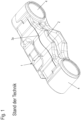
- FIG. 1 and 2 a cast iron bridge of a disc brake is shown, with two through openings 4 connected to each other by a bridge body 1, which run parallel and spaced from each other and each serve to accommodate an adjusting spindle.
- the bridge is shown according to the prior art, in which, due to manufacturing reasons, a mold parting seam 3a) delimiting a molding slope is formed at a distance from an outer edge of the bridge body 1, which extends linearly over the bridge body 1 from one through opening 4 to the other.
- the Figure 2 shows a bridge according to the invention, in which the mold dividing seam 3b) runs parallel to the course of the associated outer edge 2 of the bridge body 1.
- the outer edge 2 has a contour that deviates from the linear course, as does the mold dividing seam 3b).
- the Figure 3 represents a cross-section through the bridge body 1, with a recess 6 formed on one side for the attachment of a brake lever and an opposite recess 5 for receiving a compression spring which, in the assembled position of the bridge, is supported on a cover of the brake caliper.
- the mold parting slope is provided in the upper wall area of the bridge body 1 delimiting the recess 5, wherein the mold parting slope can be provided on the opposite wall areas.
- the Figure 4 shows an enlarged section corresponding to the marking A in Figure 3 , which depicts part of the wall of the bridge body 1.
- the mold dividing seam 3b) is visible, as is the mold dividing seam 3a) according to the prior art.
- the wall in the area of the mold dividing seam 3b) is thicker than the wall according to the prior art in this area, whereby the mold dividing seam 3a) runs significantly further away from the outer edge 2, which forms the front side of the wall.
Landscapes
- Engineering & Computer Science (AREA)
- General Engineering & Computer Science (AREA)
- Mechanical Engineering (AREA)
- Transportation (AREA)
- Braking Arrangements (AREA)
Abstract
Description
- Die Erfindung betrifft eine aus Gusseisen bestehende Brücke einer Scheibenbremse für ein Nutzfahrzeug nach dem Oberbegriff des Anspruchs 1.
- Eine solche Brücke ist Bestandteil einer in einem Bremssattel angeordneten Zuspanneinrichtung, die des Weiteren einen schwenkbaren Bremshebel aufweist. Bei einer Bremsung wird die Brücke und darin gelagerte Bremsstempel in Richtung einer Bremsscheibe verschoben, wobei die Bremsstempel gegen einen Bremsbelag gedrückt werden, der an eine fahrzeugseitige Bremsscheibe gepresst wird.
- Die Fertigung der Brücke erfolgt im Gießverfahren, wozu eine geteilte Form Verwendung findet, mit jeweils einem von einer Modellhälfte geformten Bett.
- Der gerade Formteilungsverlauf, der durch eine Formteilungsnaht erkennbar ist, begrenzt eine technisch notwendige Ausformschräge, die von einer Außenkante der Brücke ansteigt, jedoch zu einer deutlich dünneren Wandstärke führt. Dies ist der Bereich, der in Funktion der Brücke am höchsten belastet wird.
- Eine Verdickung der Wandstärke ist allerdings bei den gegebenen, durch den Bremssattel vorgegebenen Bauraumverhältnissen nicht in dem gewünschten und für eine optimale Belastbarkeit notwendigen Maß realisierbar.
- Dadurch bedingt ist zumindest die Standzeit der Brücke eingeschränkt und muss bei Bedarf, also wenn die Dauerbelastung in dem entsprechenden Bereich zu groß wird, getauscht werden.
- Unabhängig davon, dass allein aufgrund der Raumverhältnisse die Wandstärke der Brücke in dem besagten Bereich nicht beliebig dick ausgeführt sein kann, würde eine solche Ausgestaltung auch eine deutliche Erhöhung des Gewichts der Brücke mit sich bringen, was der steten Forderung nach einer Gewichtsreduzierung der Scheibenbremse insgesamt entgegenstünde.
- Überdies würde eine Verdickung der Wandstärke aufgrund des höheren Materialeinsatzes zu einer Verteuerung der Herstellung führen, was ebenfalls kontraproduktiv wäre.
- Der Erfindung liegt die Aufgabe zugrunde, eine Brücke der gattungsgemäßen Art so weiterzuentwickeln, dass ihre Belastbarkeit mit geringem konstruktivem und fertigungstechnischem Aufwand erhöht wird.
- Diese Aufgabe wird durch eine Brücke mit den Merkmalen des Anspruchs 1 gelöst.
- Danach verläuft die Formteilungsnaht parallel zum Verlauf der zugeordneten Außenkante des Brückenkörpers, wobei sich diese Außenkante von einer Durchgangsöffnung zur anderen erstreckt, die parallel und abständig zueinander angeordnet sind und die der Aufnahme jeweils einer Stellspindel dienen.
- Bevorzugt ist dabei die Außenkante maßgeblich, die einer Ausnehmung des Brückenkörpers für die Aufnahme einer Druckfeder aufweist, die in komplettierter Ausbildung der Scheibenbremse sich andererseits an einem Verschlussdeckel abstützt, mit dem der Aufnahmeraum des Bremssattels der Scheibenbremse verschlossen ist.
- Durch die erfindungsgemäße Ausgestaltung ist die Formteilungsnaht näher an der Außenkante des Brückenkörpers als die Formteilungsnaht nach dem Stand der Technik. Daraus ergibt sich im Belastungsbereich eine deutliche Verstärkung der Wandung einerseits und eine Reduzierung der Wandung im weiteren Verlauf, bezogen auf die axiale Erstreckung der Durchgangsöffnungen.
- Während dieser Bereich bislang überdimensioniert war, insbesondere da die Belastung auf der der Außenkante abgewandten Seite der Formteilungsnaht geringer ist, ist die Wandstärke in diesem Bereich nun optimiert.
- Daraus ergibt sich eine Materialersparnis, die sowohl zu einer Gewichtsreduzierung der Brücke führt wie auch zu einer Reduzierung der Herstellungskosten.
- Die fertigungsbedingt notwendige Formteilungsschräge, ausgehend von der Formteilungsnaht hin zur Außenkante, ist in der für die Entformung notwendigen Neigung gegeben, wobei die Länge der Formteilungsschräge im Querschnitt des Brückenkopfes gesehen kürzer ist als die nach dem Stand der Technik, jedoch, wie erwähnt, ausreichend für die Entformung nach dem Gießen.
- Wie genannt, ist die Formteilungsnaht der Außenkante des Brückenkörpers zugeordnet, die die Ausnehmung für die genannte Druckfeder begrenzt. Denkbar ist aber auch, die Formteilungsnaht und damit die Formteilungsschräge auf der gegenüberliegenden Seite, also an beiden Breitseiten des Brückenkörpers vorzusehen.
- Die Brücke nach der Erfindung entspricht in ihren wesentlichen Außenabmessungen einer Brücke nach dem Stand der Technik, d.h., die vorgegebenen Bauraummaße werden uneingeschränkt eingehalten. Überdies ist die neue Brücke gegenüber einer bekannten kostenneutral herstellbar und im Bedarfsfall als Austauschteil in eine vorhandene Scheibenbremse einsetzbar.
- Weitere vorteilhafte Ausbildungen der Erfindung sind in den Unteransprüchen gekennzeichnet.
- Ein Ausführungsbeispiel der Erfindung wird nachfolgend anhand der beigefügten Zeichnungen beschrieben.
- Es zeigen:
- Figur 1
- eine Brücke nach dem Stand der Technik in einer perspektivischen Ansicht
- Figur 2
- eine Brücke gemäß der Erfindung, gleichfalls perspektivisch dargestellt,
- Figur 3
- einen Querschnitt durch die Brücke nach
Figur 2 - Figur 4
- einen vergrößerten Ausschnitt der Brücke nach
Figur 3 , gemäß der Ausschnittangabe A inFigur 3 . - In den
Figuren 1 und2 ist eine aus Gusseisen bestehende Brücke einer Scheibenbremse dargestellt, mit zwei durch einen Brückenkörper 1 miteinander verbundenen Durchgangsöffnungen 4, die parallel und abständig zueinander verlaufen und der Aufnahme jeweils einer Stellspindel dienen. - In der
Figur 1 ist die Brücke nach dem Stand der Technik abgebildet, bei der fertigungsbedingt abständig zu einer Außenkante des Brückenkörpers 1 eine eine Ausformschräge begrenzende Formteilungsnaht 3a) gebildet ist, die sich linear über den Brückenkörper 1 von einer Durchgangsöffnung 4 zur anderen erstreckt. - Die
Figur 2 zeigt eine Brücke nach der Erfindung, bei der die Formteilungsnaht 3b) parallel zum Verlauf der zugeordneten Außenkante 2 des Brückenkörpers 1 verläuft. - Es ist zu erkennen, dass die Außenkante 2 einen vom linearen Verlauf abweichende Kontur aufweist, ebenso wie die Formteilungsnaht 3b).
- Die
Figur 3 stellt einen Querschnitt durch den Brückenkörper 1 dar, mit einer an einer Seite ausgebildeten Mulde 6 zur Anlage eines Bremshebels und einer gegenüberliegenden Ausnehmung 5 zur Aufnahme einer Druckfeder, die sich in montierter Stellung der Brücke an einem Verschlussdeckel des Bremssattels abstützt. - Die Formteilungsschräge ist in dem die Ausnehmung 5 begrenzenden, oberseitigen Wandbereich des Brückenkörpers 1 vorgesehen, wobei die Formteilungsschräge an den sich gegenüberliegenden Wandbereichen vorgesehen sein kann.
- Die
Figur 4 zeigt einen vergrößerten Ausschnitt entsprechend der Kennzeichnung A inFigur 3 , der einen Teil der Wandung des Brückenkörpers 1 abbildet. - Zur Verdeutlichung der Erfindung ist die Formteilungsnaht 3b) erkennbar, ebenso wie die Formteilungsnaht 3a) nach dem Stand der Technik.
- So ist zu sehen, dass die Wand im Bereich der Formteilungsnaht 3b) dicker ist als die Wand nach dem Stand der Technik in diesem Bereich, wobei die Formteilungsnaht 3a) deutlich weiter entfernt von der Außenkante 2 verläuft, die die Stirnseite der Wand bildet.
-
- 1
- Brückenkörper
- 2
- Außenkante
- 3a
- Formteilungsnaht
- 3b
- Formteilungsnaht
- 4
- Durchgangsöffnung
- 5
- Ausnehmung
- 6
- Mulde
Claims (5)
- Aus Gusseisen bestehende Brücke einer Scheibenbremse, mit zwei durch einen Brückenkörper (1) miteinander verbundenen Durchgangsöffnungen (4) zur Aufnahme jeweils einer Stellspindel, wobei fertigungsbedingt abständig zu einer Außenkante (2) des Brückenkörpers (1) eine Ausformschräge begrenzende Formteilungsnaht (3b) gebildet ist, dadurch gekennzeichnet, dass die Formteilungsnaht (3b) parallel zum Verlauf der zugeordneten Außenkante (2) des Brückenkörpers (1) verläuft.
- Brücke nach Anspruch 1,
dadurch gekennzeichnet, dass
eine Ausformschräge an beiden Breitseiten des Brückenkörpers (1) vorgesehen ist. - Brücke nach Anspruch 1 oder 2,
dadurch gekennzeichnet, dass
die Formteilungsnaht (3b) benachbart zu der eine Ausnehmung (5) für eine Druckfeder begrenzenden Außenkante (2) vorgesehen ist. - Brücke einem der vorstehenden Ansprüche,
dadurch gekennzeichnet, dass
der Verlauf der Außenkante (2) von einer linearen Ausrichtung abweichend verläuft. - Brücke nach einem der vorstehenden Ansprüche,
dadurch gekennzeichnet, dass
die Außenkante (2) durch die Stirnseite der die Ausnehmung (5) begrenzenden Wandung gebildet ist.
Applications Claiming Priority (1)
| Application Number | Priority Date | Filing Date | Title |
|---|---|---|---|
| DE202023104959.1U DE202023104959U1 (de) | 2023-08-31 | 2023-08-31 | Aus Gusseisen bestehende Brücke einer Scheibenbremse |
Publications (1)
| Publication Number | Publication Date |
|---|---|
| EP4517126A1 true EP4517126A1 (de) | 2025-03-05 |
Family
ID=88238692
Family Applications (1)
| Application Number | Title | Priority Date | Filing Date |
|---|---|---|---|
| EP24188361.0A Pending EP4517126A1 (de) | 2023-08-31 | 2024-07-12 | Aus gusseisen bestehende brücke einer scheibenbremse |
Country Status (4)
| Country | Link |
|---|---|
| US (1) | US20250075761A1 (de) |
| EP (1) | EP4517126A1 (de) |
| CN (1) | CN119532340A (de) |
| DE (1) | DE202023104959U1 (de) |
Citations (1)
| Publication number | Priority date | Publication date | Assignee | Title |
|---|---|---|---|---|
| DE102014106535A1 (de) * | 2014-05-09 | 2015-11-12 | Knorr-Bremse Systeme für Nutzfahrzeuge GmbH | Scheibenbremse für ein Nutzfahrzeug |
Family Cites Families (2)
| Publication number | Priority date | Publication date | Assignee | Title |
|---|---|---|---|---|
| WO1993003290A1 (en) * | 1991-08-07 | 1993-02-18 | Brake And Clutch Industries Australia Pty. Ltd. | Disc brake caliper and method of making same |
| DE10106591C1 (de) * | 2001-02-13 | 2002-08-14 | Lucas Automotive Gmbh | Verfahren zum spanlosen Formen und anschließenden spanenden Nachbearbeiten eines Bremssattels |
-
2023
- 2023-08-31 DE DE202023104959.1U patent/DE202023104959U1/de active Active
-
2024
- 2024-07-12 EP EP24188361.0A patent/EP4517126A1/de active Pending
- 2024-08-28 CN CN202411188573.1A patent/CN119532340A/zh active Pending
- 2024-08-30 US US18/820,418 patent/US20250075761A1/en active Pending
Patent Citations (1)
| Publication number | Priority date | Publication date | Assignee | Title |
|---|---|---|---|---|
| DE102014106535A1 (de) * | 2014-05-09 | 2015-11-12 | Knorr-Bremse Systeme für Nutzfahrzeuge GmbH | Scheibenbremse für ein Nutzfahrzeug |
Also Published As
| Publication number | Publication date |
|---|---|
| DE202023104959U1 (de) | 2023-09-15 |
| CN119532340A (zh) | 2025-02-28 |
| US20250075761A1 (en) | 2025-03-06 |
Similar Documents
| Publication | Publication Date | Title |
|---|---|---|
| DE102009018223A1 (de) | Pneumatisch oder elektromechanisch betätigbare Scheibenbremse | |
| EP1611367B1 (de) | Hydraulisch dämpfendes gummibuchsenlager für vertikale montage | |
| EP3550171B1 (de) | Blattfedereinrichtung für ein fahrzeug und verfahren zum herstellen einer solchen blattfedereinrichtung | |
| EP1108646A2 (de) | Strukturbauteil | |
| DE2930601A1 (de) | Bremsbacken fuer scheibenbremsen | |
| DE102014108500B4 (de) | Zuspanneinrichtung für eine Scheibenbremse | |
| DE102011121785A1 (de) | Radscheibe für ein Schienenfahrzeug | |
| EP3170678B1 (de) | Radnabe | |
| DE102012006093B4 (de) | Scheibenbremse für ein Nutzfahrzeug | |
| DE102015210287A1 (de) | Parksperrenanordnung | |
| EP3855039B1 (de) | Aus gusseisen bestehender bremssattel | |
| DE102019206654A1 (de) | Fahrzeugluftreifen | |
| DE202023104959U1 (de) | Aus Gusseisen bestehende Brücke einer Scheibenbremse | |
| DE102010026236A1 (de) | Pneumatische Aufhängung und Verwendung für eine Lastkraftwagen-Fahrerkabine | |
| DE102015222055A1 (de) | Strukturbauteil für ein Kraftfahrzeug | |
| DE10307689A1 (de) | Ausleger | |
| DE102008027049A1 (de) | Scheibenbremse für ein Nutzfahrzeug | |
| DE102014115766A1 (de) | Scheibenbremse für ein Nutzfahrzeug | |
| DE10150214B4 (de) | Scheibenbremse, insbesondere für ein Nutzfahrzeug | |
| EP3199828B1 (de) | Bremsbelaghalterung einer fahrzeug-scheibenbremse sowie niederhalter für die befestigung von bremsbelägen | |
| DE102005034555A1 (de) | Stützwinde | |
| DE102013221512A1 (de) | Karosserie eines Kraftfahrzeugs | |
| AT504953B1 (de) | Handbremseinrichtung | |
| DE102016210458A1 (de) | Torsionsquerträger, insbesondere für eine Verbundlenkerachse und Kraftfahrzeug aufweisend den Torsionsquerträger | |
| DE102007061421A1 (de) | Bremssattel einer Scheibenbremse |
Legal Events
| Date | Code | Title | Description |
|---|---|---|---|
| PUAI | Public reference made under article 153(3) epc to a published international application that has entered the european phase |
Free format text: ORIGINAL CODE: 0009012 |
|
| STAA | Information on the status of an ep patent application or granted ep patent |
Free format text: STATUS: THE APPLICATION HAS BEEN PUBLISHED |
|
| AK | Designated contracting states |
Kind code of ref document: A1 Designated state(s): AL AT BE BG CH CY CZ DE DK EE ES FI FR GB GR HR HU IE IS IT LI LT LU LV MC ME MK MT NL NO PL PT RO RS SE SI SK SM TR |
|
| STAA | Information on the status of an ep patent application or granted ep patent |
Free format text: STATUS: REQUEST FOR EXAMINATION WAS MADE |
|
| 17P | Request for examination filed |
Effective date: 20250905 |
|
| STAA | Information on the status of an ep patent application or granted ep patent |
Free format text: STATUS: EXAMINATION IS IN PROGRESS |
|
| 17Q | First examination report despatched |
Effective date: 20251210 |
|
| GRAP | Despatch of communication of intention to grant a patent |
Free format text: ORIGINAL CODE: EPIDOSNIGR1 |
|
| STAA | Information on the status of an ep patent application or granted ep patent |
Free format text: STATUS: GRANT OF PATENT IS INTENDED |
|
| INTG | Intention to grant announced |
Effective date: 20260626 |