EP4516368A1 - Hoch-tief maschine - Google Patents
Hoch-tief maschine Download PDFInfo
- Publication number
- EP4516368A1 EP4516368A1 EP24171878.2A EP24171878A EP4516368A1 EP 4516368 A1 EP4516368 A1 EP 4516368A1 EP 24171878 A EP24171878 A EP 24171878A EP 4516368 A1 EP4516368 A1 EP 4516368A1
- Authority
- EP
- European Patent Office
- Prior art keywords
- frame
- pair
- user
- rotating
- seating
- Prior art date
- Legal status (The legal status is an assumption and is not a legal conclusion. Google has not performed a legal analysis and makes no representation as to the accuracy of the status listed.)
- Granted
Links
Images


Classifications
-
- A—HUMAN NECESSITIES
- A63—SPORTS; GAMES; AMUSEMENTS
- A63B—APPARATUS FOR PHYSICAL TRAINING, GYMNASTICS, SWIMMING, CLIMBING, OR FENCING; BALL GAMES; TRAINING EQUIPMENT
- A63B21/00—Exercising apparatus for developing or strengthening the muscles or joints of the body by working against a counterforce, with or without measuring devices
- A63B21/06—User-manipulated weights
- A63B21/0615—User-manipulated weights pivoting about a fixed horizontal fulcrum
-
- A—HUMAN NECESSITIES
- A63—SPORTS; GAMES; AMUSEMENTS
- A63B—APPARATUS FOR PHYSICAL TRAINING, GYMNASTICS, SWIMMING, CLIMBING, OR FENCING; BALL GAMES; TRAINING EQUIPMENT
- A63B21/00—Exercising apparatus for developing or strengthening the muscles or joints of the body by working against a counterforce, with or without measuring devices
- A63B21/06—User-manipulated weights
- A63B21/08—User-manipulated weights anchored at one end
-
- A—HUMAN NECESSITIES
- A63—SPORTS; GAMES; AMUSEMENTS
- A63B—APPARATUS FOR PHYSICAL TRAINING, GYMNASTICS, SWIMMING, CLIMBING, OR FENCING; BALL GAMES; TRAINING EQUIPMENT
- A63B21/00—Exercising apparatus for developing or strengthening the muscles or joints of the body by working against a counterforce, with or without measuring devices
- A63B21/40—Interfaces with the user related to strength training; Details thereof
- A63B21/4027—Specific exercise interfaces
- A63B21/4029—Benches specifically adapted for exercising
-
- A—HUMAN NECESSITIES
- A63—SPORTS; GAMES; AMUSEMENTS
- A63B—APPARATUS FOR PHYSICAL TRAINING, GYMNASTICS, SWIMMING, CLIMBING, OR FENCING; BALL GAMES; TRAINING EQUIPMENT
- A63B21/00—Exercising apparatus for developing or strengthening the muscles or joints of the body by working against a counterforce, with or without measuring devices
- A63B21/40—Interfaces with the user related to strength training; Details thereof
- A63B21/4027—Specific exercise interfaces
- A63B21/4033—Handles, pedals, bars or platforms
- A63B21/4035—Handles, pedals, bars or platforms for operation by hand
-
- A—HUMAN NECESSITIES
- A63—SPORTS; GAMES; AMUSEMENTS
- A63B—APPARATUS FOR PHYSICAL TRAINING, GYMNASTICS, SWIMMING, CLIMBING, OR FENCING; BALL GAMES; TRAINING EQUIPMENT
- A63B21/00—Exercising apparatus for developing or strengthening the muscles or joints of the body by working against a counterforce, with or without measuring devices
- A63B21/40—Interfaces with the user related to strength training; Details thereof
- A63B21/4041—Interfaces with the user related to strength training; Details thereof characterised by the movements of the interface
- A63B21/4047—Pivoting movement
-
- A—HUMAN NECESSITIES
- A63—SPORTS; GAMES; AMUSEMENTS
- A63B—APPARATUS FOR PHYSICAL TRAINING, GYMNASTICS, SWIMMING, CLIMBING, OR FENCING; BALL GAMES; TRAINING EQUIPMENT
- A63B23/00—Exercising apparatus specially adapted for particular parts of the body
- A63B23/035—Exercising apparatus specially adapted for particular parts of the body for limbs, i.e. upper or lower limbs, e.g. simultaneously
- A63B23/03516—For both arms together or both legs together; Aspects related to the co-ordination between right and left side limbs of a user
- A63B23/03525—Supports for both feet or both hands performing simultaneously the same movement, e.g. single pedal or single handle
-
- A—HUMAN NECESSITIES
- A63—SPORTS; GAMES; AMUSEMENTS
- A63B—APPARATUS FOR PHYSICAL TRAINING, GYMNASTICS, SWIMMING, CLIMBING, OR FENCING; BALL GAMES; TRAINING EQUIPMENT
- A63B23/00—Exercising apparatus specially adapted for particular parts of the body
- A63B23/035—Exercising apparatus specially adapted for particular parts of the body for limbs, i.e. upper or lower limbs, e.g. simultaneously
- A63B23/12—Exercising apparatus specially adapted for particular parts of the body for limbs, i.e. upper or lower limbs, e.g. simultaneously for upper limbs or related muscles, e.g. chest, upper back or shoulder muscles
-
- A—HUMAN NECESSITIES
- A63—SPORTS; GAMES; AMUSEMENTS
- A63B—APPARATUS FOR PHYSICAL TRAINING, GYMNASTICS, SWIMMING, CLIMBING, OR FENCING; BALL GAMES; TRAINING EQUIPMENT
- A63B2208/00—Characteristics or parameters related to the user or player
- A63B2208/02—Characteristics or parameters related to the user or player posture
- A63B2208/0228—Sitting on the buttocks
- A63B2208/0233—Sitting on the buttocks in 90/90 position, like on a chair
-
- A—HUMAN NECESSITIES
- A63—SPORTS; GAMES; AMUSEMENTS
- A63B—APPARATUS FOR PHYSICAL TRAINING, GYMNASTICS, SWIMMING, CLIMBING, OR FENCING; BALL GAMES; TRAINING EQUIPMENT
- A63B2225/00—Miscellaneous features of sport apparatus, devices or equipment
- A63B2225/09—Adjustable dimensions
-
- A—HUMAN NECESSITIES
- A63—SPORTS; GAMES; AMUSEMENTS
- A63B—APPARATUS FOR PHYSICAL TRAINING, GYMNASTICS, SWIMMING, CLIMBING, OR FENCING; BALL GAMES; TRAINING EQUIPMENT
- A63B2225/00—Miscellaneous features of sport apparatus, devices or equipment
- A63B2225/09—Adjustable dimensions
- A63B2225/093—Height
Definitions
- the present disclosure relates to a high-low machine, and more particularly, to a high-low machine having a first angle adjustment part and a second angle adjustment part based on each of two axes orthogonal to a grip portion, which allows a user to adjust an angle of a handle to various angles select a grip method according to the user's needs and to target specific areas for intensive exercise and select the grip method to target specific areas for intensive exercise.
- Patent Document 1 Korean Patent No. 10-1524970
- the present disclosure provides a high-low machine, having a first angle adjustment unit and a second angle adjustment unit based on each of two axes perpendicular to a grip unit, which allows a user to adjust a handle at various angles and select a grip method according to the user's needs to target specific areas for intensive exercise.
- the present disclosure provides a high-low machine that allows exercise to be performed by selecting a single-arm motion or a two-arm motion, thereby enabling customized motion performance according to the purpose of exercise.
- the present disclosure provides a high-low machine which allows users to adjust the height of a seat, the angle of a knee support, and the like, depending on their various body sizes.
- a high-low machine comprises: a support frame (110) placed on a floor; a main body frame (120) connected to the support frame (110) to form a support structure; a weight portion (130) which is rotatably mounted at one point of the main body frame (120) and on which a weight plate is mounted; a rotating portion (140) rotatably mounted at another point of the main body frame (120); a connecting portion (150) provided to connect the weight portion (130) and the rotating portion (140) to transfer load of the weight plate to the rotating portion (140), the connecting portion (150) being adjustable in length; a grip unit (160) connected to one end of the rotating portion (140) and providing a space for a user to grip; and a seating unit (170) connected to the support frame (110) and disposed in front of the main body frame (120) to provide a space for the user to sit, wherein the grip unit (160) includes: a pair of handles (161) provided for the user to grip; a pair of first angle adjustment
- the main body frame (120) may include: a standing frame (121) erected from the support frame 110; a pair of parallel frames (122) arranged parallel to the standing frame (121); a pair of inclined frames (123) each provided to extend from an upper end of each of the pair of parallel frames (122), one end of each of the pair of inclined frames (123) being connected to the standing frame (121); and a connection frame (124) perpendicularly connecting the pair of parallel frames (122).
- the rotating portion (140) may include: a first rotating frame (141) that has two curved parts and is provided in a 'U'-shaped bar with both ends spaced apart; a second rotating frame (142) having one end coupled to one point of the first rotating frame (141) and having a bar-shape with one curved portion and one bent portion; a reinforcement frame (143) coupled at both ends to another point of the first rotating frame (141) and one point of the second rotating frame (142); and a weight (144) provided at one end of the second rotating frame (143) to balance the weight with the grip unit (160).
- the grip unit (160) may be coupled to one end of the first rotating frame (141), the other end of the first rotating frame (141) may be linked to an upper end of the standing frame (121) to be rotatable, and one end of the connection portion (150) may be linked to one point of the second rotating frame (142).
- the seating unit (170) may include: a first seating frame (171) erected from the support frame 110 and having a curved portion; a second seating frame (172) connecting one point of the first seating frame (171) and the support frame (110); a footrest portion (173) resting on the support frame (110) and disposed on a lower side of the first seating frame (171); a seat portion (174) disposed on an upper side of the footrest portion (172), connected to the second seating frame (172), and providing a space for the user to sit; a height adjustment portion (175) connecting the second seating frame (172) and the seat portion (174), and provided to slide in a height direction along the second seating frame (172) or to be fixed to the second seating frame (172); a knee support portion (176) mounted to the first seating frame (171), disposed higher than the seat portion (174) to be placed above the knees of the user seated on the seat portion (174); and a support angle adjustment unit (177) that adjusts an angle of the knee support portion (176) with respect to the
- the first angle adjustment unit and the second angle adjustment unit based on each of two axes perpendicular to the grip unit, a user can adjust the handle at various angles and select a grip method according to the user's needs to target specific areas for intensive exercise.
- the user can exercise by selecting the single-arm motion or the two-arm motion, thereby enabling customized motion performance according to the purpose of exercise.
- the user can adjust the height of the seat, the angle of the knee support, and the like, which enables customized exercises depending on various body sizes of the users.
- FIGS. 1 to 8 a high-low machine 100 according to the present disclosure will be described in detail with reference to the accompanying FIGS. 1 to 8 .
- FIG. 1 is a perspective view showing the high-low machine according to one embodiment of the present disclosure
- FIG. 2 is a side view showing the high-low machine according to one embodiment of the present disclosure.
- the high-low machine 100 may include a support frame 110, a main body frame 120, a weight portion 130, a rotating portion 140, a connecting portion 150, a grip unit 160, a seating unit 170, and a mounting portion 180.
- the support frame 110 may be placed on a floor.
- the support frame 110 will be described in more detail with reference to FIG. 3 .
- FIG. 3 is a diagram showing the support frame 110 according to one embodiment of the present disclosure.
- the support frame 110 may include a support bending frame 111, a support connection frame 112, and a support protrusion frame 113.
- the support bending frame 111 may have one curved portion, and a pair of support bending frames 111 may be arranged as mirror images.
- the support connection frame 112 may perpendicularly connect the pair of support bending frames 111.
- the supporting protruding frame 113 may be provided in a bar shape between the pair of support bending frames 111.
- the support bending frame 111, the support connection frame 112, and the support protrusion frame 113 may be provided as a frame structure.
- the support frame 110 may be formed by connecting the support bending frame 111, the support connection frame 112, and the support protrusion frame 113 to each other.
- the support frame 110 may further include friction fixing parts 114 at multiple lower points of the support bending frame 111, the support connection frame 112, and the support protrusion frame 113.
- the friction fixing parts 114 may fix the high-low machine 100 through friction with the ground so that the high-low machine 100 does not slip or move.
- the main body frame 120 may be connected to the support frame 110 to form a support structure.
- the main body frame 120 will be described in more detail with reference to FIG. 4 .
- FIG. 4 is a diagram showing the main body frame 120 according to one embodiment of the present disclosure.
- the main body frame 120 may include a standing frame 121, a pair of parallel frames 122, a pair of inclined frames 123, and a connection frame 124.
- the standing frame 121 may be erected from the support frame 110.
- the pair of parallel frames 122 may be arranged parallel to the standing frame 121.
- Each of the pair of inclined frames 123 may be provided to extend from an upper end of each of the pair of parallel frames 122, and one end may be connected to the standing frame 121.
- connection frame 124 may perpendicularly connect the pair of parallel frames 122.
- the main body frame 120 may be provided with a weight plate storage portion (not shown) capable of holding weight plates of various weights at multiple points.
- the weight plate storage portion may be provided to protrude from at least one of the standing frame 121, the pair of parallel frames 122, the pair of inclined frames 123, and the connection frame 124, so that a central hole (not shown) of the weight plate is fitted onto the weight plate storage portion and the weight plate is mounted thereon.
- the weight portion 130 may be rotatably mounted at one point of the main body frame 120, and a weight plate may be mounted thereon.
- the weight portion 130 will be described in more detail with reference to FIG. 5 .
- FIG. 5 is a diagram showing the weight portion 130 according to one embodiment of the present disclosure.
- the weight portion 130 may include a weight frame 131 and a pair of weight plate storage bars 132.
- One end of the weight frame 131 may be rotatably linked to the connection frame 124.
- the pair of weight plate storage bars 132 may be provided to protrude in a bar shape on both sides of the other end of the weight frame 131, and arranged in a mirror image with respect to the weight frame 131, and the weight plate can be mounted thereon.
- the rotating portion 140 may be rotatably mounted at another point of the main body frame 120.
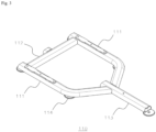
- the rotating portion 140 may be provided by combining oval cylindrical pipes. The rotating portion 140 will be described in more detail with reference to FIG. 6 .
- FIG. 6 is a diagram showing the rotating portion 140 according to one embodiment of the present disclosure.
- the rotating portion 140 may include a first rotating frame 141, a second rotating frame 142, a reinforcement frame 143, and a weight 144.
- the first rotating frame 141 may have two curved portions and be provided in a 'U'-shaped bar with both ends spaced apart.
- the second rotating frame 142 has one end coupled to one point of the first rotating frame 141 and may be provided in a bar shape having one curved portion and one bent portion.
- the reinforcement frame 143 may be coupled at both ends to another point of the first rotating frame 141 and one point of the second rotating frame 142.
- the weight 144 may be provided at one end of the second rotating frame 143 to balance the weight with the grip unit 160.
- the weight 144 balances the weight of the grip unit 160, thereby preventing an accident caused by the grip unit 160 falling due to its load.
- the connecting portion 150 connects the weight portion 130 and the rotating portion 140 to transfer the load of the weight plate to the rotating portion 140, and may be provided to be adjustable in length. By making the connecting portion 150 adjustable in length, the distance between the rotating portion 140 and the weight plates can be adjusted, which allows exercise by adjusting the weight in various ways even with the weight plates of the same weight.
- the grip unit 160 may be connected to one end of the rotating portion 140 and may provide a grip space for the user to grip.
- the grip space means providing a member that the user can grip with his or her hand.
- the grip unit 160 will be described in more detail with reference to FIG. 7 .
- FIG. 7 is a diagram showing the grip unit 160 according to one embodiment of the present disclosure.
- the grip unit 160 may include a pair of handles 161, a pair of first angle adjustment units 162, and a pair of second angle adjustment units 163.
- the pair of handles 161 may be provided for a user to grip.
- Each of the pair of first angle adjustment units 162 may be provided at one end of each of the pair of handles 161, and may be provided to adjust the angle of the handle 161 with respect to a first axis.
- Each of the pair of second angle adjustment units 163 connects one end of each of the pair of first angle adjustment units 162 and one end of the rotating portion 140, and may be provided to adjust the angle of the handle 161 with respect to a second axis orthogonal to the first axis.
- the grip unit 160 When the grip unit 160 descends due to an external force applied by the user, it descends in an arc motion, and when the external force applied by the user is released, it returns along the descended path by the weight of the weight plates 131.
- the grip unit 160 is provided with the first angle adjustment unit 162 and the second angle adjustment unit 163 based on each of two orthogonal axes, so that the user can adjust the angle of the handle 161 and select the grip method according to the user's needs to target a specific body portion for intensive exercise.
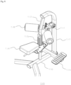
- the seating unit 170 may be connected to the support frame 110 and disposed in front of the main body frame 120 to provide a space for the user to sit.
- the seating unit 170 will be described in more detail with reference to FIG. 8 .
- FIG. 8 is a diagram showing the seating unit 170 according to one embodiment of the present disclosure.
- the seating unit 170 may include a first seating frame 171, a second seating frame 172, a footrest unit 173, a seat portion 174, and a height adjustment portion 175, a knee support portion 176, and a support angle adjustment unit 177.
- the first seating frame 171 may be erected from the support frame 110 and may have a curved portion.
- the second seating frame 172 may connect one point of the first seating frame 171 and the support frame 110.
- the footrest portion 173 may rest on the support frame 110 and may be disposed on the lower side of the first seating frame 171.
- the seat portion 174 may be disposed on the upper side of the footrest portion 173 to be connected to the second seating frame 172, and may provide a space for the user to sit.
- the seat portion 174 may be made of a material that allows the user to feel cushioning.
- the height adjustment portion 175 may connect the second seating frame 172 and the seat portion 174, and may be provided to slide in a height direction along the second seating frame 172 or to be fixed to the second seating frame 172. The user can exercise in a more comfortable state by adjusting the height adjustment portion 175 to change the height of the seat portion 174 from the floor.
- the knee support portion 176 may be mounted to the first seating frame 171, and may be disposed higher than the seat portion 174 to be placed above the knees of the user seated on the seat portion 174.
- the knee support portion 176 may be provided with a pair of knee support pieces (not shown) for securing both thighs or knees of the user.
- the support angle adjustment unit 177 can adjust the angle of the knee support portion 176 with respect to the first seating frame 171.
- the first angle adjustment unit 162, the second angle adjustment unit 163, and the support angle adjustment unit 177 may be provided with a plurality of angle adjusting holes (not shown) having a circular arc shape, and may be adjusted at desired angle by inserting an angle fixing pin into one of the plurality of angle adjusting holes.
- the mounting portion 180 may be provided to protrude at a preset angle at one point of the support frame 110, and may be provided to define a lowering limit of the weight portion 130.
- FIGS. 9A and 9B are diagrams showing the operation of the high-low machine according to one embodiment of the present disclosure.
- FIG. 9A shows a state before the user lowers the grip unit 160
- FIG. 9B shows a state after the user lowers the grip unit 160.
- the user can fix a weight plate of desired weight to the weight portion 30.
- the user can adjust and fix the handle 161 at a desired angle using the first angle adjustment unit 162 and the second angle adjustment unit 163.
- the user sits on the seating unit 170 with his back toward the main body frame 120 and can adjust the height of the seating unit 174 to suit the user's body size.
- the user can adjust the angle of the knee support portion 176 using the support angle adjustment unit 177 to fix his/her legs.
- the user can exercise by lowering the grip unit 160 while gripping the handle 161 with one or both hands to move one end of the rotating portion 140 from the raised position (see FIG. 9A ) to the lowered position (see FIG.
- the above-described operation may be implemented in a state that the user faces the main body frame 120.
- the rotating portion 140 connected to the grip unit 160 rotates, and the weight portion 130 connected to the connecting portion 150 is lifted according to the rotation of the rotating portion 140.
- the weight can changed by adjusting the length of the connecting portion 150.
- the first angle adjustment unit and the second angle adjustment unit are respectively provided based on two axes orthogonal to the grip unit, so that the user can adjust the handle angle at various angles and select the grip method according to the user's needs to target his/her specific body portion for intensive exercise.
- the user can perform exercise using the high-low machine according to one embodiment of the present disclosure by selecting one arm motion or both arm motion, so that customized motion can be performed according to the purpose of exercise, and the user can adjust the height of the seat portion, the angle of the knee support portion, and the like, so that it can respond to the body sizes of various users.
Landscapes
- Health & Medical Sciences (AREA)
- Orthopedic Medicine & Surgery (AREA)
- General Health & Medical Sciences (AREA)
- Physical Education & Sports Medicine (AREA)
- Life Sciences & Earth Sciences (AREA)
- Biophysics (AREA)
- Rehabilitation Tools (AREA)
- Cardiology (AREA)
- Vascular Medicine (AREA)
Applications Claiming Priority (1)
| Application Number | Priority Date | Filing Date | Title |
|---|---|---|---|
| KR1020230114711A KR102640736B1 (ko) | 2023-08-30 | 2023-08-30 | 하이로우 머신 |
Publications (3)
| Publication Number | Publication Date |
|---|---|
| EP4516368A1 true EP4516368A1 (de) | 2025-03-05 |
| EP4516368C0 EP4516368C0 (de) | 2025-12-03 |
| EP4516368B1 EP4516368B1 (de) | 2025-12-03 |
Family
ID=90058486
Family Applications (1)
| Application Number | Title | Priority Date | Filing Date |
|---|---|---|---|
| EP24171878.2A Active EP4516368B1 (de) | 2023-08-30 | 2024-04-23 | Hoch-tief maschine |
Country Status (6)
| Country | Link |
|---|---|
| US (1) | US12521595B2 (de) |
| EP (1) | EP4516368B1 (de) |
| JP (1) | JP7704468B2 (de) |
| KR (1) | KR102640736B1 (de) |
| CN (1) | CN117899414B (de) |
| AU (1) | AU2024202034A1 (de) |
Families Citing this family (4)
| Publication number | Priority date | Publication date | Assignee | Title |
|---|---|---|---|---|
| JP2024046245A (ja) * | 2022-09-22 | 2024-04-03 | キヤノン株式会社 | 無線通信装置、無線通信装置の制御方法およびプログラム |
| JP1794988S (ja) * | 2024-04-26 | 2025-04-02 | 運動器具用の持ち手 | |
| USD1097009S1 (en) * | 2024-04-26 | 2025-10-07 | Newtech Wellness Corporation | Exercise handle |
| KR102748271B1 (ko) * | 2024-06-13 | 2024-12-31 | (주)뉴텍웰니스 | 버티컬 풀다운 머신 |
Citations (5)
| Publication number | Priority date | Publication date | Assignee | Title |
|---|---|---|---|---|
| US20070093364A1 (en) * | 2005-10-20 | 2007-04-26 | Roger Batca | Exercise machine with adjustable arms rotatable about three axes |
| KR101524970B1 (ko) | 2014-02-07 | 2015-06-10 | 이석종 | 상체운동기구 |
| CN218076153U (zh) * | 2022-05-07 | 2022-12-20 | 广州源动智慧体育科技有限公司 | 综合力量训练设备 |
| KR102522850B1 (ko) * | 2022-02-10 | 2023-04-18 | 주식회사 지아이 | 역기 운동장치 |
| US20230249029A1 (en) * | 2022-02-10 | 2023-08-10 | Newtech Wellness Corporation | Exercise equipment for back |
Family Cites Families (24)
| Publication number | Priority date | Publication date | Assignee | Title |
|---|---|---|---|---|
| US4623144A (en) * | 1985-01-31 | 1986-11-18 | Diversified Products Corporation | Weight lifting type abdominal/back exercising apparatus |
| US4951939A (en) * | 1988-10-11 | 1990-08-28 | Peters Dale W | Exercise machine |
| US5050873A (en) * | 1990-04-26 | 1991-09-24 | Hammer Corporation | Pulldown exercise machine |
| US5273504A (en) * | 1991-09-13 | 1993-12-28 | Hammer Strength Corporation | Behind the neck pulldown exercise machine |
| US5273505A (en) * | 1991-10-21 | 1993-12-28 | Hammer Strength Corporation | High row exercise machine |
| US6579213B1 (en) * | 2000-02-29 | 2003-06-17 | Hoist Fitness Systems | Exercise arm assembly for exercise machine |
| US20020052268A1 (en) * | 2000-05-03 | 2002-05-02 | Vicente Morcillo-Quintero | Exercise machine providing for natural movement |
| US7108641B2 (en) * | 2000-05-03 | 2006-09-19 | Nautilus, Inc. | Exercise equipment with multi-positioning handles |
| US6746378B2 (en) * | 2001-06-08 | 2004-06-08 | Nautilus Human Performance Systems, Inc. | Lat pulldown weight training machine |
| US7794371B2 (en) * | 2003-08-04 | 2010-09-14 | Hoist Fitness Systems, Inc. | Lat exercise machine with self-aligning pivoting user support |
| US7361125B2 (en) * | 2003-11-03 | 2008-04-22 | Hoist Fitness Systems, Inc. | Rigid arm pull down exercise machine |
| US7101322B2 (en) * | 2004-01-05 | 2006-09-05 | Carle John T | Weight exercise device |
| US7322906B2 (en) * | 2004-08-13 | 2008-01-29 | Webber Randall T | Exercise arm assembly for exercise machine |
| JP3939720B2 (ja) * | 2004-10-18 | 2007-07-04 | 株式会社コナミスポーツ&ライフ | トレーニング装置 |
| JP4063821B2 (ja) * | 2004-12-28 | 2008-03-19 | 株式会社ワールドウィングエンタープライズ | トレーニング器具 |
| CA2696781C (en) * | 2007-08-03 | 2016-01-19 | Grzegorz Lyszczarz | A three-point adjustment multi-purpose exercise machine |
| JP5567936B2 (ja) * | 2009-08-24 | 2014-08-06 | 是吉興業株式会社 | トレーニング装置 |
| EP3765162B1 (de) * | 2018-03-19 | 2022-01-19 | Hoist Fitness Systems, Inc. | Klapp- und haltegriffsystem für seitlich herunterziehbare übungsgeräte |
| KR102090777B1 (ko) * | 2019-04-25 | 2020-03-18 | 황병문 | 다목적 근육 운동기구 |
| BR102019025572A2 (pt) * | 2019-12-03 | 2021-06-15 | Indio Da Costa Licensing Ltda. | Dispositivo regulador de peso, equipamento de ginástica dotado de dispositivo regulador de peso e método para regulagem de peso de um equipamento de ginástica através de um dispositivo regulador |
| KR102296498B1 (ko) * | 2020-11-27 | 2021-09-01 | (주)뉴텍웰니스 | 레터럴 레이즈 머신 |
| KR102294781B1 (ko) * | 2021-03-30 | 2021-08-26 | 변현정 | 기립각도 조절식 플라이 머신 |
| KR200497233Y1 (ko) * | 2021-05-03 | 2023-09-06 | 변현정 | 그립각도 조절식 회전손잡이 |
| DE202022102400U1 (de) * | 2022-05-03 | 2022-05-12 | Dr. Wolff Sports & Prevention Gmbh | Krafttrainingsgerät |
-
2023
- 2023-08-30 KR KR1020230114711A patent/KR102640736B1/ko active Active
- 2023-11-21 US US18/515,258 patent/US12521595B2/en active Active
- 2023-12-04 CN CN202311648115.7A patent/CN117899414B/zh active Active
-
2024
- 2024-03-28 AU AU2024202034A patent/AU2024202034A1/en active Pending
- 2024-04-08 JP JP2024062127A patent/JP7704468B2/ja active Active
- 2024-04-23 EP EP24171878.2A patent/EP4516368B1/de active Active
Patent Citations (5)
| Publication number | Priority date | Publication date | Assignee | Title |
|---|---|---|---|---|
| US20070093364A1 (en) * | 2005-10-20 | 2007-04-26 | Roger Batca | Exercise machine with adjustable arms rotatable about three axes |
| KR101524970B1 (ko) | 2014-02-07 | 2015-06-10 | 이석종 | 상체운동기구 |
| KR102522850B1 (ko) * | 2022-02-10 | 2023-04-18 | 주식회사 지아이 | 역기 운동장치 |
| US20230249029A1 (en) * | 2022-02-10 | 2023-08-10 | Newtech Wellness Corporation | Exercise equipment for back |
| CN218076153U (zh) * | 2022-05-07 | 2022-12-20 | 广州源动智慧体育科技有限公司 | 综合力量训练设备 |
Also Published As
| Publication number | Publication date |
|---|---|
| CN117899414B (zh) | 2024-09-10 |
| EP4516368C0 (de) | 2025-12-03 |
| US12521595B2 (en) | 2026-01-13 |
| US20250073521A1 (en) | 2025-03-06 |
| JP7704468B2 (ja) | 2025-07-08 |
| JP2025036047A (ja) | 2025-03-14 |
| EP4516368B1 (de) | 2025-12-03 |
| KR102640736B1 (ko) | 2024-02-27 |
| AU2024202034A1 (en) | 2025-03-20 |
| CN117899414A (zh) | 2024-04-19 |
Similar Documents
| Publication | Publication Date | Title |
|---|---|---|
| EP4516368A1 (de) | Hoch-tief maschine | |
| JP3117451B2 (ja) | 運動機械 | |
| US7654938B2 (en) | Exercise machine with pivoting user support having multiple pivot linkage | |
| US6394936B1 (en) | Convergent exercise machine and method | |
| US7794371B2 (en) | Lat exercise machine with self-aligning pivoting user support | |
| CN219023120U (zh) | 锻炼器材系统 | |
| KR102469818B1 (ko) | 등 운동기구 | |
| WO1996020758A1 (en) | Device for exercising the lower back | |
| KR102511110B1 (ko) | 벤트 오버 로우 머신 | |
| CA3247521A1 (en) | HIGH-LOW MACHINE | |
| KR102748271B1 (ko) | 버티컬 풀다운 머신 | |
| JP2724132B2 (ja) | 筋力鍛練装置 | |
| JP7489737B1 (ja) | ドロップスクワットマシン(Drop squat machine) | |
| JP7763892B2 (ja) | ベントオーバーローマシン | |
| KR102620480B1 (ko) | 시티드 로우 | |
| CN117597174B (zh) | 俯身划船运动机 | |
| JP2892985B2 (ja) | 筋力鍛練装置 | |
| JPH0646753U (ja) | 調節可能なテーブルを備えた多機能の体操器具 |
Legal Events
| Date | Code | Title | Description |
|---|---|---|---|
| PUAI | Public reference made under article 153(3) epc to a published international application that has entered the european phase |
Free format text: ORIGINAL CODE: 0009012 |
|
| STAA | Information on the status of an ep patent application or granted ep patent |
Free format text: STATUS: REQUEST FOR EXAMINATION WAS MADE |
|
| 17P | Request for examination filed |
Effective date: 20240423 |
|
| AK | Designated contracting states |
Kind code of ref document: A1 Designated state(s): AL AT BE BG CH CY CZ DE DK EE ES FI FR GB GR HR HU IE IS IT LI LT LU LV MC ME MK MT NL NO PL PT RO RS SE SI SK SM TR |
|
| GRAP | Despatch of communication of intention to grant a patent |
Free format text: ORIGINAL CODE: EPIDOSNIGR1 |
|
| STAA | Information on the status of an ep patent application or granted ep patent |
Free format text: STATUS: GRANT OF PATENT IS INTENDED |
|
| INTG | Intention to grant announced |
Effective date: 20250709 |
|
| GRAS | Grant fee paid |
Free format text: ORIGINAL CODE: EPIDOSNIGR3 |
|
| GRAA | (expected) grant |
Free format text: ORIGINAL CODE: 0009210 |
|
| STAA | Information on the status of an ep patent application or granted ep patent |
Free format text: STATUS: THE PATENT HAS BEEN GRANTED |
|
| AK | Designated contracting states |
Kind code of ref document: B1 Designated state(s): AL AT BE BG CH CY CZ DE DK EE ES FI FR GB GR HR HU IE IS IT LI LT LU LV MC ME MK MT NL NO PL PT RO RS SE SI SK SM TR |
|
| REG | Reference to a national code |
Ref country code: CH Ref legal event code: F10 Free format text: ST27 STATUS EVENT CODE: U-0-0-F10-F00 (AS PROVIDED BY THE NATIONAL OFFICE) Effective date: 20251203 Ref country code: GB Ref legal event code: FG4D |
|
| REG | Reference to a national code |
Ref country code: IE Ref legal event code: FG4D |
|
| U01 | Request for unitary effect filed |
Effective date: 20251205 |
|
| U07 | Unitary effect registered |
Designated state(s): AT BE BG DE DK EE FI FR IT LT LU LV MT NL PT RO SE SI Effective date: 20251211 |