EP4516162A1 - Elektrischer lehnstuhl mit einklemmschutz - Google Patents
Elektrischer lehnstuhl mit einklemmschutz Download PDFInfo
- Publication number
- EP4516162A1 EP4516162A1 EP24192157.6A EP24192157A EP4516162A1 EP 4516162 A1 EP4516162 A1 EP 4516162A1 EP 24192157 A EP24192157 A EP 24192157A EP 4516162 A1 EP4516162 A1 EP 4516162A1
- Authority
- EP
- European Patent Office
- Prior art keywords
- leg
- reclining chair
- linkage mechanism
- electric reclining
- rest
- Prior art date
- Legal status (The legal status is an assumption and is not a legal conclusion. Google has not performed a legal analysis and makes no representation as to the accuracy of the status listed.)
- Granted
Links
Images



Classifications
-
- A—HUMAN NECESSITIES
- A47—FURNITURE; DOMESTIC ARTICLES OR APPLIANCES; COFFEE MILLS; SPICE MILLS; SUCTION CLEANERS IN GENERAL
- A47C—CHAIRS; SOFAS; BEDS
- A47C1/00—Chairs adapted for special purposes
- A47C1/02—Reclining or easy chairs
- A47C1/031—Reclining or easy chairs having coupled concurrently adjustable supporting parts
- A47C1/034—Reclining or easy chairs having coupled concurrently adjustable supporting parts the parts including a leg-rest or foot-rest
-
- A—HUMAN NECESSITIES
- A47—FURNITURE; DOMESTIC ARTICLES OR APPLIANCES; COFFEE MILLS; SPICE MILLS; SUCTION CLEANERS IN GENERAL
- A47C—CHAIRS; SOFAS; BEDS
- A47C1/00—Chairs adapted for special purposes
- A47C1/02—Reclining or easy chairs
- A47C1/031—Reclining or easy chairs having coupled concurrently adjustable supporting parts
- A47C1/034—Reclining or easy chairs having coupled concurrently adjustable supporting parts the parts including a leg-rest or foot-rest
- A47C1/0342—Reclining or easy chairs having coupled concurrently adjustable supporting parts the parts including a leg-rest or foot-rest in combination with movable backrest-seat unit or back-rest
- A47C1/0345—Reclining or easy chairs having coupled concurrently adjustable supporting parts the parts including a leg-rest or foot-rest in combination with movable backrest-seat unit or back-rest characterised by foot-rests actuated by lazy-tongs
-
- A—HUMAN NECESSITIES
- A47—FURNITURE; DOMESTIC ARTICLES OR APPLIANCES; COFFEE MILLS; SPICE MILLS; SUCTION CLEANERS IN GENERAL
- A47C—CHAIRS; SOFAS; BEDS
- A47C1/00—Chairs adapted for special purposes
- A47C1/02—Reclining or easy chairs
- A47C1/031—Reclining or easy chairs having coupled concurrently adjustable supporting parts
- A47C1/036—Reclining or easy chairs having coupled concurrently adjustable supporting parts the parts including a head-rest
- A47C1/037—Reclining or easy chairs having coupled concurrently adjustable supporting parts the parts including a head-rest in combination with a leg-rest or foot-rest
-
- A—HUMAN NECESSITIES
- A47—FURNITURE; DOMESTIC ARTICLES OR APPLIANCES; COFFEE MILLS; SPICE MILLS; SUCTION CLEANERS IN GENERAL
- A47C—CHAIRS; SOFAS; BEDS
- A47C7/00—Parts, details, or accessories of chairs or stools
- A47C7/50—Supports for the feet or the legs
-
- A—HUMAN NECESSITIES
- A47—FURNITURE; DOMESTIC ARTICLES OR APPLIANCES; COFFEE MILLS; SPICE MILLS; SUCTION CLEANERS IN GENERAL
- A47C—CHAIRS; SOFAS; BEDS
- A47C1/00—Chairs adapted for special purposes
- A47C1/02—Reclining or easy chairs
- A47C1/022—Reclining or easy chairs having independently-adjustable supporting parts
- A47C1/024—Reclining or easy chairs having independently-adjustable supporting parts the parts, being the back-rest, or the back-rest and seat unit, having adjustable inclination
- A47C1/0242—Reclining or easy chairs having independently-adjustable supporting parts the parts, being the back-rest, or the back-rest and seat unit, having adjustable inclination by electric motors
-
- G—PHYSICS
- G08—SIGNALLING
- G08B—SIGNALLING SYSTEMS, e.g. PERSONAL CALLING SYSTEMS; ORDER TELEGRAPHS; ALARM SYSTEMS
- G08B3/00—Audible signalling systems, e.g. audible personal calling systems
Definitions
- the present invention relates to an electric reclining chair, and particularly to an electric reclining chair with anti-pinch protection.
- An electric reclining chair is drivable by electricity to adjust angles and positions of a seatback, a seat, a leg-rest, and other components, which allows users to find the most comfortable sitting position.
- the leg-rest is drivable by a linked mechanism via electric power to ascend for user's legs to be placed thereon or to be folded for the electric reclining chair to take up less space.
- leg-rest may abut and be stopped by the object when the leg-rest is to be folded later.
- the linked mechanism fails to fold the leg-rest, which may lead to structural damage between the leg-rest and the linked mechanism.
- a child or a pet may be pinched by the linked mechanism or the leg-rest if inadvertently stretching hands or feet into the space under the leg-rest.
- the main objective of the present invention is to provide an electric reclining chair with anti-pinch protection which reacts when a leg-rest pad abuts an object while being folded so as to prevent linked mechanisms of the leg-rest from structural damage and improve safety.
- the electric reclining chair with anti-pinch protection has a base, a linkage mechanism, at least one leg-rest mount, and a control module.
- the linkage mechanism is movably mounted on the base and connected to a driver.
- the at least one leg-rest mount is pivotally connected to the linkage mechanism.
- the control module has at least one sensor module and a control unit. The control unit is electrically connected to the at least one sensor module and the driver for controlling the driver to unfold or fold the linkage mechanism.
- the at least one sensor module senses pivoting of said leg-rest mount relative to the linkage mechanism to send a signal to the control unit such that the control unit controls the driver to stop folding the linkage mechanism or to unfold the linkage mechanism.
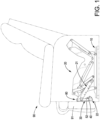
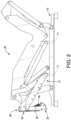
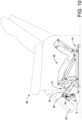
- a preferred embodiment of an electric reclining chair with anti-pinch protection in accordance with the present invention has a base 10, a linkage mechanism 20, a control module 50, a driver 60, two leg-rest components 80, a seat body 90, and two leg-rest pads 91.
- the base 10 is configured for the electric reclining chair to be placed on a flat surface (e.g. on a floor), and the linkage mechanism 20 is movably disposed on the base 10.
- the two leg-rest components 80 are disposed on the linkage mechanism 20.
- the seat body 90 is mounted on the base 10.
- the two leg-rest pads 91 are connected to the seat body 90 and respectively mounted on the two leg-rest components 80 for a user to place two legs respectively on the two leg-rest pads 91.
- the control module 50 is electrically connected to the driver 60, and the driver 60 is connected to the linkage mechanism 20 and is controllable by the control module 50 to drive the linkage mechanism 20 for folding or unfolding the linkage mechanism 20.
- the two leg-rest components 80 are configured to be actuated by and move synchronously with the linkage mechanism 20, and thereby the two leg-rest pads 91 are folded as the linkage mechanism 20 is folded and are ascended as the linkage mechanism 20 is unfolded.
- the linkage mechanism 20 has two linkage components 21 located at an end of the linkage mechanism 20 away from the base 10, and the linkage mechanism 20 is connected to the driver 60 via other links or bars such that the linkage mechanism 20 is drivable by the driver 60.
- the driver 60 may adopt an electric linear actuator.
- the two leg-rest components 80 are respectively mounted on the two linkage components 21. Detail of the links or bars of the linkage mechanism 20 may refer to conventional skills of the electric reclining chair. Also, for better understanding with the drawings, the following configurations are described with one of the two linkage components 21 and the corresponding leg-rest component 80.
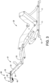
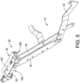
- each linkage component 21 has two swing arms 22, a first link 23, and two second links 24.
- the two swing arms 22 are respectively a first swing arm 22A and a second swing arm 22B and are connected to each other.
- the two second links 24 are spaced from each other.
- An end of each second link 24 is pivotally connected to the first link 23, and the other end of each second link 24 is pivotally connected to the first swing arm 22A.
- the first link 23, the two second links 24, and the first swing arm 22A jointly form a four-bar linkage.
- the four-bar linkage is connected to other components of the linkage mechanism 20 via the first link 23 and one of the two second links 24 to be drivable to be folded or unfolded.
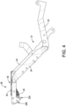
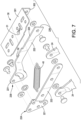
- each leg-rest component 80 has a leg-rest mount 30 and an elastic unit 40.
- the leg-rest mount 30 is pivotally mounted to the corresponding linkage component 21.
- the leg-rest mount 30 is pivotally connected to the second swing arm 22B and has multiple holes for said leg-rest pad to be fixed on the leg-rest mount 30 via fasteners such as screws.
- the elastic unit 40 is connected to the leg-rest mount 30 and the first swing arm 22A.
- the first swing arm 22A has a connecting hole 223, and the leg-rest mount 30 has a hang hole 31.
- the elastic unit 40 is specifically a tension spring. An end of the elastic unit 40 is hooked to the connecting hole 223, and the other end of the elastic unit 40 is hooked to the hang hole 31.
- the control module 50 has a control unit 51 and two sensor modules 52.
- the control unit 51 is electrically connected to the two sensor modules 52 and the driver 60.
- the two sensor modules 52 respectively correspond to the two leg-rest components 80, wherein said sensor module 52 may adopt a photoelectric sensor disposed on the second swing arm 22B.
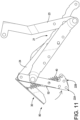
- a light emitted from an emitter of the photoelectric sensor is no longer interrupted or reflected by the leg-rest mount 30 and arrives at a receiver of the photoelectric sensor.
- the receiver detects change of the light to generate an electrical output to the control unit 51, and the control unit 51 controls the driver 60 according to the electrical output.
- said sensor module 52 may adopt any one of a micro switch, a membrane switch, a tact switch, and a pressure sensor.
- the electric reclining chair is configured to sense the obstacle in time and stop the linkage mechanism 20 from driving the leg-rest mount 30 and said leg-rest pad 91 to press the obstacle, which not only prevents the linkage mechanism 20 from structural damage but also prevents kids or pets from being pinched when they stretch hands or feet into the space under said leg-rest pad 91.
- the electric reclining chair has an alarm 71 electrically connected to the control unit 51 and controllable by the control unit 51 to make a sound.
- the alarm 71 may be a buzzer or a speaker.
- the control unit 51 controls the driver 60 to stop folding the linkage mechanism 20 or to reversely unfold the linkage mechanism 20.
- the control unit 51 controls the alarm 71 to make a sound to alarm a user about existence of the obstacle S.
- each swing arm 22 has a pivot-connecting portion 221 and an extending portion 222.
- the pivot-connecting portions 221 of the two swing arms 22 are attached to and pivotally connected to each other.
- the leg-rest mount 30 is pivotally connected to the extending portion 222 of the second swing arm 22B. Thereby, when an external force is applied on said leg-rest pad 90, the leg-rest mount 30 pivots relative to the second swing arm 22B with reference to Fig. 11 as described above.
- Said sensor module 52 is disposed on the extending portion 222 of the second swing arm 22B.
- the extending portion 222 is bended and extends from the pivot-connecting portion 221, and the extending portions 222 of the two swing arms 22 are spaced from each other; i.e. the two swing arms 22 form a fork-shaped construction.
- the leg-rest mount 30 has a mount board 301 and a side board 302.
- the side board 302 is pivotally connected to the extending portion 222 of the second swing arm 22B, and the mount board 301 perpendicularly extends from an edge of the side board 302 and extends over the extending portions 222 of the two swing arms 22.
- the elastic unit 40 is located between the extending portions 222 of the two swing arms 22, and said connecting hole 223 and said hang hole 31 for hooking the elastic unit 40 are respectively formed on the pivot-connecting portion 221 of the first swing arm 22A and the mount board 301. With the fork-shaped construction formed by the two swing arms 22 and the mount board 301 across the two swing arms 22, the elastic unit 40 is less likely to tilt and to interfere with other components during elastic deformation, which prolongs a service life of the elastic unit 40.
- the electric reclining chair further has two sensor components 11.
- the two sensor components 11 are electrically connected to the control unit 51 and disposed on an inner side of the base 10 at a spaced interval to sense whether any object enters an interior of the base 10 or not.
- said sensor components 11 may adopt a photoelectric sensor. If a pet, a kid, or other object enters the interior of the base 10 when the electric reclining chair remains static with the linkage mechanism 20 unfolded, the photoelectric sensor senses a change of light in the interior of the base 10, generates and sends an electrical signal to the control unit 51 so as to control the driver 60 to stop operating.
- control unit 51 may control the alarm 71 to make a noise so as to notify a user that an object has entered the interior of the base 10.
- the base 10 has two base rods arranged symmetrically, and said sensor component 11 may adopt laser and time-of-flight (ToF) to sense an object.
- ToF time-of-flight
- a laser beam is emitted from one of the two base rods, is reflected by the other one of the two base rods, returns to and is received at the original spot.
- said sensor component 11 measures the distance between the two base rods by the time from emitting the laser beam to receiving the laser beam.
- the control unit 51 controls the driver 60 to stop operating according to the change of the distance measured by said sensor component 11.
- said sensor component 11 may adopt a photo interrupter.
- the object interrupts a light emitted by said sensor component 11 from one of the two base rods to the other one of the two base rods to be received by said sensor component 11, which allows said sensor component 11 to sense the object.
- configuration and number of said sensor components 11 can be determined according to requirement, which is not limited to the preferred embodiment.
- the electric reclining chair may have a covering board connected to the seat body 90 and disposed between the two linkage components 21 of the linkage mechanism 20 to prevent objects from entering the interior of the base 10.
Landscapes
- Health & Medical Sciences (AREA)
- Dentistry (AREA)
- General Health & Medical Sciences (AREA)
- Chairs For Special Purposes, Such As Reclining Chairs (AREA)
- Chair Legs, Seat Parts, And Backrests (AREA)
- Electrotherapy Devices (AREA)
Applications Claiming Priority (1)
| Application Number | Priority Date | Filing Date | Title |
|---|---|---|---|
| TW112209203U TWM654289U (zh) | 2023-08-29 | 2023-08-29 | 防壓夾之電動椅 |
Publications (3)
| Publication Number | Publication Date |
|---|---|
| EP4516162A1 true EP4516162A1 (de) | 2025-03-05 |
| EP4516162C0 EP4516162C0 (de) | 2026-03-11 |
| EP4516162B1 EP4516162B1 (de) | 2026-03-11 |
Family
ID=91620005
Family Applications (1)
| Application Number | Title | Priority Date | Filing Date |
|---|---|---|---|
| EP24192157.6A Active EP4516162B1 (de) | 2023-08-29 | 2024-07-31 | Elektrischer lehnstuhl mit einklemmschutz |
Country Status (3)
| Country | Link |
|---|---|
| US (1) | US12599234B2 (de) |
| EP (1) | EP4516162B1 (de) |
| TW (1) | TWM654289U (de) |
Families Citing this family (3)
| Publication number | Priority date | Publication date | Assignee | Title |
|---|---|---|---|---|
| DE102021122430A1 (de) * | 2021-08-31 | 2023-03-02 | Ferdinand Lusch Gmbh | Schwenkbeschlag eines sitzmöbels zum verstellen eines fussteils und sitzmöbel mit verstellbarem fussteil |
| US20240315452A1 (en) * | 2023-03-23 | 2024-09-26 | L&P Property Management Company | High-leg recliner seating mechanism |
| CN219813618U (zh) * | 2023-05-24 | 2023-10-13 | 海宁和力机械科技有限公司 | 座椅骨架及休闲座椅 |
Citations (2)
| Publication number | Priority date | Publication date | Assignee | Title |
|---|---|---|---|---|
| WO2010026420A2 (en) * | 2008-09-02 | 2010-03-11 | Brandvital Ltd. | Articulated chairs |
| US20180031441A1 (en) * | 2016-07-26 | 2018-02-01 | Dragon Crown Industries Limited | Collision sensor |
Family Cites Families (3)
| Publication number | Priority date | Publication date | Assignee | Title |
|---|---|---|---|---|
| FR2808433B1 (fr) * | 2000-05-04 | 2002-08-02 | Labinal | Procede de gestion de la cinematique d'un siege a positions preprogrammees et siege le mettant en oeuvre |
| US20160242548A1 (en) * | 2015-02-20 | 2016-08-25 | Christopher Scott Barnum | Automated Adjustable Seating System |
| WO2018199255A1 (ja) * | 2017-04-28 | 2018-11-01 | テイ・エス テック株式会社 | シートユニット、車両及び乗物用シート |
-
2023
- 2023-08-29 TW TW112209203U patent/TWM654289U/zh unknown
-
2024
- 2024-07-30 US US18/788,574 patent/US12599234B2/en active Active
- 2024-07-31 EP EP24192157.6A patent/EP4516162B1/de active Active
Patent Citations (2)
| Publication number | Priority date | Publication date | Assignee | Title |
|---|---|---|---|---|
| WO2010026420A2 (en) * | 2008-09-02 | 2010-03-11 | Brandvital Ltd. | Articulated chairs |
| US20180031441A1 (en) * | 2016-07-26 | 2018-02-01 | Dragon Crown Industries Limited | Collision sensor |
Also Published As
| Publication number | Publication date |
|---|---|
| TWM654289U (zh) | 2024-04-21 |
| US12599234B2 (en) | 2026-04-14 |
| EP4516162C0 (de) | 2026-03-11 |
| EP4516162B1 (de) | 2026-03-11 |
| US20250072611A1 (en) | 2025-03-06 |
Similar Documents
| Publication | Publication Date | Title |
|---|---|---|
| EP4516162B1 (de) | Elektrischer lehnstuhl mit einklemmschutz | |
| CA2498395A1 (en) | Control mechanism for seating unit | |
| US6152529A (en) | Motor driven rocking chair | |
| JPWO2004026211A1 (ja) | 可動ベッド | |
| US20010006300A1 (en) | Chair assisting rising movements | |
| JP2004538037A (ja) | 多数の区間を備えた電動手術台 | |
| EP1081730A2 (de) | Wippschalter | |
| WO2018203476A1 (ja) | 電動家具 | |
| US20150241857A1 (en) | Operating unit of a control device of an adjusting drive for furniture | |
| US6902233B2 (en) | Reclining chair with extendible leg rest | |
| US8588978B2 (en) | Robot | |
| US7819476B2 (en) | Lift chair and a chair base frame with a force balance mechanism for use therewith | |
| AU2024200308A1 (en) | Anti-pinch system for an electric seat | |
| CN220777881U (zh) | 防压夹的电动椅 | |
| JP3245044U (ja) | 挟み込みを防止する電動椅子 | |
| JP7420636B2 (ja) | スイッチ装置 | |
| GB2463076A (en) | Articulating chair with sensor | |
| CN109204866B (zh) | 登机桥及其触机停止装置 | |
| JP2005245808A (ja) | 椅子及び段差解消機 | |
| JP5719694B2 (ja) | 起床式ベッド装置 | |
| CN216611437U (zh) | 一种平衡车踏板组件及平衡车 | |
| KR200168727Y1 (ko) | 자세 교정용 의자 | |
| JP2022506980A (ja) | 車椅子のフットセンサー警報器 | |
| TWI815514B (zh) | 椅子型按摩機 | |
| CN108577310B (zh) | 防近视驼背用椅子 |
Legal Events
| Date | Code | Title | Description |
|---|---|---|---|
| PUAI | Public reference made under article 153(3) epc to a published international application that has entered the european phase |
Free format text: ORIGINAL CODE: 0009012 |
|
| STAA | Information on the status of an ep patent application or granted ep patent |
Free format text: STATUS: THE APPLICATION HAS BEEN PUBLISHED |
|
| AK | Designated contracting states |
Kind code of ref document: A1 Designated state(s): AL AT BE BG CH CY CZ DE DK EE ES FI FR GB GR HR HU IE IS IT LI LT LU LV MC ME MK MT NL NO PL PT RO RS SE SI SK SM TR |
|
| STAA | Information on the status of an ep patent application or granted ep patent |
Free format text: STATUS: REQUEST FOR EXAMINATION WAS MADE |
|
| 17P | Request for examination filed |
Effective date: 20250522 |
|
| GRAP | Despatch of communication of intention to grant a patent |
Free format text: ORIGINAL CODE: EPIDOSNIGR1 |
|
| STAA | Information on the status of an ep patent application or granted ep patent |
Free format text: STATUS: GRANT OF PATENT IS INTENDED |
|
| INTG | Intention to grant announced |
Effective date: 20251008 |
|
| GRAS | Grant fee paid |
Free format text: ORIGINAL CODE: EPIDOSNIGR3 |
|
| GRAA | (expected) grant |
Free format text: ORIGINAL CODE: 0009210 |
|
| STAA | Information on the status of an ep patent application or granted ep patent |
Free format text: STATUS: THE PATENT HAS BEEN GRANTED |
|
| AK | Designated contracting states |
Kind code of ref document: B1 Designated state(s): AL AT BE BG CH CY CZ DE DK EE ES FI FR GB GR HR HU IE IS IT LI LT LU LV MC ME MK MT NL NO PL PT RO RS SE SI SK SM TR |
|
| REG | Reference to a national code |
Ref country code: CH Ref legal event code: F10 Free format text: ST27 STATUS EVENT CODE: U-0-0-F10-F00 (AS PROVIDED BY THE NATIONAL OFFICE) Effective date: 20260311 Ref country code: GB Ref legal event code: FG4D |
|
| REG | Reference to a national code |
Ref country code: DE Ref legal event code: R096 Ref document number: 602024003112 Country of ref document: DE |
|
| REG | Reference to a national code |
Ref country code: IE Ref legal event code: FG4D |
|
| U01 | Request for unitary effect filed |
Effective date: 20260325 |
|
| U07 | Unitary effect registered |
Designated state(s): AT BE BG DE DK EE FI FR IT LT LU LV MT NL PT RO SE SI Effective date: 20260401 |