EP4513655A2 - Separatorlaminat für lithiumsekundärbatterie, elektrodenanordnung damit und lithiumsekundärbatterie damit - Google Patents
Separatorlaminat für lithiumsekundärbatterie, elektrodenanordnung damit und lithiumsekundärbatterie damit Download PDFInfo
- Publication number
- EP4513655A2 EP4513655A2 EP24221530.9A EP24221530A EP4513655A2 EP 4513655 A2 EP4513655 A2 EP 4513655A2 EP 24221530 A EP24221530 A EP 24221530A EP 4513655 A2 EP4513655 A2 EP 4513655A2
- Authority
- EP
- European Patent Office
- Prior art keywords
- separator
- secondary battery
- lithium secondary
- separators
- negative electrode
- Prior art date
- Legal status (The legal status is an assumption and is not a legal conclusion. Google has not performed a legal analysis and makes no representation as to the accuracy of the status listed.)
- Pending
Links
Images


Classifications
-
- H—ELECTRICITY
- H01—ELECTRIC ELEMENTS
- H01M—PROCESSES OR MEANS, e.g. BATTERIES, FOR THE DIRECT CONVERSION OF CHEMICAL ENERGY INTO ELECTRICAL ENERGY
- H01M10/00—Secondary cells; Manufacture thereof
- H01M10/05—Accumulators with non-aqueous electrolyte
- H01M10/052—Li-accumulators
-
- H—ELECTRICITY
- H01—ELECTRIC ELEMENTS
- H01M—PROCESSES OR MEANS, e.g. BATTERIES, FOR THE DIRECT CONVERSION OF CHEMICAL ENERGY INTO ELECTRICAL ENERGY
- H01M10/00—Secondary cells; Manufacture thereof
- H01M10/05—Accumulators with non-aqueous electrolyte
- H01M10/052—Li-accumulators
- H01M10/0525—Rocking-chair batteries, i.e. batteries with lithium insertion or intercalation in both electrodes; Lithium-ion batteries
-
- H—ELECTRICITY
- H01—ELECTRIC ELEMENTS
- H01M—PROCESSES OR MEANS, e.g. BATTERIES, FOR THE DIRECT CONVERSION OF CHEMICAL ENERGY INTO ELECTRICAL ENERGY
- H01M10/00—Secondary cells; Manufacture thereof
- H01M10/05—Accumulators with non-aqueous electrolyte
- H01M10/058—Construction or manufacture
- H01M10/0583—Construction or manufacture of accumulators with folded construction elements except wound ones, i.e. folded positive or negative electrodes or separators, e.g. with "Z"-shaped electrodes or separators
-
- H—ELECTRICITY
- H01—ELECTRIC ELEMENTS
- H01M—PROCESSES OR MEANS, e.g. BATTERIES, FOR THE DIRECT CONVERSION OF CHEMICAL ENERGY INTO ELECTRICAL ENERGY
- H01M10/00—Secondary cells; Manufacture thereof
- H01M10/05—Accumulators with non-aqueous electrolyte
- H01M10/058—Construction or manufacture
- H01M10/0585—Construction or manufacture of accumulators having only flat construction elements, i.e. flat positive electrodes, flat negative electrodes and flat separators
-
- H—ELECTRICITY
- H01—ELECTRIC ELEMENTS
- H01M—PROCESSES OR MEANS, e.g. BATTERIES, FOR THE DIRECT CONVERSION OF CHEMICAL ENERGY INTO ELECTRICAL ENERGY
- H01M10/00—Secondary cells; Manufacture thereof
- H01M10/42—Methods or arrangements for servicing or maintenance of secondary cells or secondary half-cells
- H01M10/4235—Safety or regulating additives or arrangements in electrodes, separators or electrolyte
-
- H—ELECTRICITY
- H01—ELECTRIC ELEMENTS
- H01M—PROCESSES OR MEANS, e.g. BATTERIES, FOR THE DIRECT CONVERSION OF CHEMICAL ENERGY INTO ELECTRICAL ENERGY
- H01M4/00—Electrodes
- H01M4/02—Electrodes composed of, or comprising, active material
- H01M4/13—Electrodes for accumulators with non-aqueous electrolyte, e.g. for lithium-accumulators; Processes of manufacture thereof
- H01M4/134—Electrodes based on metals, Si or alloys
-
- H—ELECTRICITY
- H01—ELECTRIC ELEMENTS
- H01M—PROCESSES OR MEANS, e.g. BATTERIES, FOR THE DIRECT CONVERSION OF CHEMICAL ENERGY INTO ELECTRICAL ENERGY
- H01M4/00—Electrodes
- H01M4/02—Electrodes composed of, or comprising, active material
- H01M4/36—Selection of substances as active materials, active masses, active liquids
- H01M4/38—Selection of substances as active materials, active masses, active liquids of elements or alloys
- H01M4/381—Alkaline or alkaline earth metals elements
- H01M4/382—Lithium
-
- H—ELECTRICITY
- H01—ELECTRIC ELEMENTS
- H01M—PROCESSES OR MEANS, e.g. BATTERIES, FOR THE DIRECT CONVERSION OF CHEMICAL ENERGY INTO ELECTRICAL ENERGY
- H01M4/00—Electrodes
- H01M4/02—Electrodes composed of, or comprising, active material
- H01M4/64—Carriers or collectors
- H01M4/66—Selection of materials
- H01M4/661—Metal or alloys, e.g. alloy coatings
-
- H—ELECTRICITY
- H01—ELECTRIC ELEMENTS
- H01M—PROCESSES OR MEANS, e.g. BATTERIES, FOR THE DIRECT CONVERSION OF CHEMICAL ENERGY INTO ELECTRICAL ENERGY
- H01M50/00—Constructional details or processes of manufacture of the non-active parts of electrochemical cells other than fuel cells, e.g. hybrid cells
- H01M50/40—Separators; Membranes; Diaphragms; Spacing elements inside cells
- H01M50/409—Separators, membranes or diaphragms characterised by the material
- H01M50/411—Organic material
- H01M50/414—Synthetic resins, e.g. thermoplastics or thermosetting resins
- H01M50/417—Polyolefins
-
- H—ELECTRICITY
- H01—ELECTRIC ELEMENTS
- H01M—PROCESSES OR MEANS, e.g. BATTERIES, FOR THE DIRECT CONVERSION OF CHEMICAL ENERGY INTO ELECTRICAL ENERGY
- H01M50/00—Constructional details or processes of manufacture of the non-active parts of electrochemical cells other than fuel cells, e.g. hybrid cells
- H01M50/40—Separators; Membranes; Diaphragms; Spacing elements inside cells
- H01M50/409—Separators, membranes or diaphragms characterised by the material
- H01M50/411—Organic material
- H01M50/414—Synthetic resins, e.g. thermoplastics or thermosetting resins
- H01M50/426—Fluorocarbon polymers
-
- H—ELECTRICITY
- H01—ELECTRIC ELEMENTS
- H01M—PROCESSES OR MEANS, e.g. BATTERIES, FOR THE DIRECT CONVERSION OF CHEMICAL ENERGY INTO ELECTRICAL ENERGY
- H01M50/00—Constructional details or processes of manufacture of the non-active parts of electrochemical cells other than fuel cells, e.g. hybrid cells
- H01M50/40—Separators; Membranes; Diaphragms; Spacing elements inside cells
- H01M50/409—Separators, membranes or diaphragms characterised by the material
- H01M50/446—Composite material consisting of a mixture of organic and inorganic materials
-
- H—ELECTRICITY
- H01—ELECTRIC ELEMENTS
- H01M—PROCESSES OR MEANS, e.g. BATTERIES, FOR THE DIRECT CONVERSION OF CHEMICAL ENERGY INTO ELECTRICAL ENERGY
- H01M50/00—Constructional details or processes of manufacture of the non-active parts of electrochemical cells other than fuel cells, e.g. hybrid cells
- H01M50/40—Separators; Membranes; Diaphragms; Spacing elements inside cells
- H01M50/409—Separators, membranes or diaphragms characterised by the material
- H01M50/449—Separators, membranes or diaphragms characterised by the material having a layered structure
- H01M50/451—Separators, membranes or diaphragms characterised by the material having a layered structure comprising layers of only organic material and layers containing inorganic material
-
- H—ELECTRICITY
- H01—ELECTRIC ELEMENTS
- H01M—PROCESSES OR MEANS, e.g. BATTERIES, FOR THE DIRECT CONVERSION OF CHEMICAL ENERGY INTO ELECTRICAL ENERGY
- H01M50/00—Constructional details or processes of manufacture of the non-active parts of electrochemical cells other than fuel cells, e.g. hybrid cells
- H01M50/40—Separators; Membranes; Diaphragms; Spacing elements inside cells
- H01M50/409—Separators, membranes or diaphragms characterised by the material
- H01M50/449—Separators, membranes or diaphragms characterised by the material having a layered structure
- H01M50/457—Separators, membranes or diaphragms characterised by the material having a layered structure comprising three or more layers
-
- H—ELECTRICITY
- H01—ELECTRIC ELEMENTS
- H01M—PROCESSES OR MEANS, e.g. BATTERIES, FOR THE DIRECT CONVERSION OF CHEMICAL ENERGY INTO ELECTRICAL ENERGY
- H01M50/00—Constructional details or processes of manufacture of the non-active parts of electrochemical cells other than fuel cells, e.g. hybrid cells
- H01M50/40—Separators; Membranes; Diaphragms; Spacing elements inside cells
- H01M50/46—Separators, membranes or diaphragms characterised by their combination with electrodes
- H01M50/461—Separators, membranes or diaphragms characterised by their combination with electrodes with adhesive layers between electrodes and separators
-
- H—ELECTRICITY
- H01—ELECTRIC ELEMENTS
- H01M—PROCESSES OR MEANS, e.g. BATTERIES, FOR THE DIRECT CONVERSION OF CHEMICAL ENERGY INTO ELECTRICAL ENERGY
- H01M50/00—Constructional details or processes of manufacture of the non-active parts of electrochemical cells other than fuel cells, e.g. hybrid cells
- H01M50/40—Separators; Membranes; Diaphragms; Spacing elements inside cells
- H01M50/463—Separators, membranes or diaphragms characterised by their shape
- H01M50/466—U-shaped, bag-shaped or folded
-
- H—ELECTRICITY
- H01—ELECTRIC ELEMENTS
- H01M—PROCESSES OR MEANS, e.g. BATTERIES, FOR THE DIRECT CONVERSION OF CHEMICAL ENERGY INTO ELECTRICAL ENERGY
- H01M50/00—Constructional details or processes of manufacture of the non-active parts of electrochemical cells other than fuel cells, e.g. hybrid cells
- H01M50/40—Separators; Membranes; Diaphragms; Spacing elements inside cells
- H01M50/489—Separators, membranes, diaphragms or spacing elements inside the cells, characterised by their physical properties, e.g. swelling degree, hydrophilicity or shut down properties
- H01M50/491—Porosity
-
- H—ELECTRICITY
- H01—ELECTRIC ELEMENTS
- H01M—PROCESSES OR MEANS, e.g. BATTERIES, FOR THE DIRECT CONVERSION OF CHEMICAL ENERGY INTO ELECTRICAL ENERGY
- H01M50/00—Constructional details or processes of manufacture of the non-active parts of electrochemical cells other than fuel cells, e.g. hybrid cells
- H01M50/40—Separators; Membranes; Diaphragms; Spacing elements inside cells
- H01M50/489—Separators, membranes, diaphragms or spacing elements inside the cells, characterised by their physical properties, e.g. swelling degree, hydrophilicity or shut down properties
- H01M50/494—Tensile strength
-
- H—ELECTRICITY
- H01—ELECTRIC ELEMENTS
- H01M—PROCESSES OR MEANS, e.g. BATTERIES, FOR THE DIRECT CONVERSION OF CHEMICAL ENERGY INTO ELECTRICAL ENERGY
- H01M50/00—Constructional details or processes of manufacture of the non-active parts of electrochemical cells other than fuel cells, e.g. hybrid cells
- H01M50/40—Separators; Membranes; Diaphragms; Spacing elements inside cells
- H01M50/489—Separators, membranes, diaphragms or spacing elements inside the cells, characterised by their physical properties, e.g. swelling degree, hydrophilicity or shut down properties
- H01M50/497—Ionic conductivity
-
- H—ELECTRICITY
- H01—ELECTRIC ELEMENTS
- H01M—PROCESSES OR MEANS, e.g. BATTERIES, FOR THE DIRECT CONVERSION OF CHEMICAL ENERGY INTO ELECTRICAL ENERGY
- H01M4/00—Electrodes
- H01M4/02—Electrodes composed of, or comprising, active material
- H01M2004/026—Electrodes composed of, or comprising, active material characterised by the polarity
- H01M2004/027—Negative electrodes
-
- H—ELECTRICITY
- H01—ELECTRIC ELEMENTS
- H01M—PROCESSES OR MEANS, e.g. BATTERIES, FOR THE DIRECT CONVERSION OF CHEMICAL ENERGY INTO ELECTRICAL ENERGY
- H01M50/00—Constructional details or processes of manufacture of the non-active parts of electrochemical cells other than fuel cells, e.g. hybrid cells
- H01M50/40—Separators; Membranes; Diaphragms; Spacing elements inside cells
- H01M50/409—Separators, membranes or diaphragms characterised by the material
- H01M50/443—Particulate material
-
- Y—GENERAL TAGGING OF NEW TECHNOLOGICAL DEVELOPMENTS; GENERAL TAGGING OF CROSS-SECTIONAL TECHNOLOGIES SPANNING OVER SEVERAL SECTIONS OF THE IPC; TECHNICAL SUBJECTS COVERED BY FORMER USPC CROSS-REFERENCE ART COLLECTIONS [XRACs] AND DIGESTS
- Y02—TECHNOLOGIES OR APPLICATIONS FOR MITIGATION OR ADAPTATION AGAINST CLIMATE CHANGE
- Y02E—REDUCTION OF GREENHOUSE GAS [GHG] EMISSIONS, RELATED TO ENERGY GENERATION, TRANSMISSION OR DISTRIBUTION
- Y02E60/00—Enabling technologies; Technologies with a potential or indirect contribution to GHG emissions mitigation
- Y02E60/10—Energy storage using batteries
-
- Y—GENERAL TAGGING OF NEW TECHNOLOGICAL DEVELOPMENTS; GENERAL TAGGING OF CROSS-SECTIONAL TECHNOLOGIES SPANNING OVER SEVERAL SECTIONS OF THE IPC; TECHNICAL SUBJECTS COVERED BY FORMER USPC CROSS-REFERENCE ART COLLECTIONS [XRACs] AND DIGESTS
- Y02—TECHNOLOGIES OR APPLICATIONS FOR MITIGATION OR ADAPTATION AGAINST CLIMATE CHANGE
- Y02P—CLIMATE CHANGE MITIGATION TECHNOLOGIES IN THE PRODUCTION OR PROCESSING OF GOODS
- Y02P70/00—Climate change mitigation technologies in the production process for final industrial or consumer products
- Y02P70/50—Manufacturing or production processes characterised by the final manufactured product
Definitions
- the present disclosure relates to a separator laminate for lithium secondary battery, an electrode assembly including the same, and a lithium secondary battery including the same.
- a secondary battery is a representative example of an electrochemical device that utilizes such electrochemical energy, and the range of use thereof tends to be gradually expanding.
- the electrode assembly built into a battery case is a chargeable and dischargeable power generation element composed of a laminated structure of positive electrode/separator/negative electrode, and is classified as a jelly-roll type electrode assembly having a configuration of winding a long-sheet type positive electrode and a long-sheet type negative electrode in a state in which a separator is interposed therebetween, a stack type electrode assembly having a configuration in which pluralities of positive electrodes and negative electrodes each having a predetermined size are consecutively stacked in a state in which separators are disposed between the two electrodes, or as a combination thereof, a stack/folding type electrode assembly having a construction of winding bi-cells or full cells, including a positive electrode, a negative electrode and a separator, into a long-sheet type separation film, and a laminate/stack type electrode assembly having a configuration of stacking after laminating the bi-cell or full cell.
- a lithium secondary battery has a structure in which a non-aqueous electrolyte is impregnated into an electrode assembly comprising a positive electrode, a negative electrode, and a porous separator.
- the positive electrode is generally manufactured by coating a positive electrode mixture including a positive electrode active material onto aluminum foil
- the negative electrode is manufactured by coating a negative electrode mixture including a negative electrode active material onto a copper foil.
- the positive electrode active material uses a lithium transition metal oxide
- the negative active material uses a carbon-based material.
- a lithium metal battery using lithium metal itself has been commercialized.
- a lithium ion battery uses a carbon-based material (theoretical capacity: 372 mAh/g) as a negative active material
- a lithium metal battery uses lithium metal (theoretical capacity: 3600 mAh/g) as a negative electrode active material, and thus, have an advantage that the amount of energy is theoretically increased by 10 times or more.
- the lithium secondary battery causes a short circuit due to various factors, and as an example, the point at which the transition metal eluted from the positive electrode active material is electrodeposited on the negative electrode surface is the starting point of the metal column, and lithium metal is further electrodeposited at the starting point, and as a result, the metal column may grow through the pores of the separator and makes contact with the positive electrode, thereby causing a micro-short-circuit.
- This micro-short circuit allows lithium metal batteries to expose to a lot of danger as lithium metal has a higher reactivity compared to carbon-based materials.
- Such a micro-short circuit may also shorten the life of the lithium secondary battery.
- the separation space formed between the separators can induce the vertically growing metal columns to grow horizontally even if the separator adjacent to the negative electrode is pierced by a metal column, thereby providing a separator laminate for a lithium secondary battery capable of inhibiting a short circuit by the remaining separator.
- the separator laminate of the one embodiment is suitable for use in an electrode assembly having a lamination structure.
- At least one separator contained in the separator laminate is composed of an SRS separator or a free-standing organic/inorganic mixed film, it is excellent in mechanical strength and can strengthen a primary defense against attacks from metal column.
- the separator laminate is those obtained by laminating N (however, N ⁇ 2) separators. Therefore, in contrast to the case of using one separator, the overall thickness may be increased, thereby improving mechanical strength.
- the upper limit of N may be 5, specifically 3.
- the total thickness of the separator laminate may satisfy 1 um to 60 um, specifically 9 um to 30 um.
- the separator laminate even if one separator adjacent to the negative electrode in the separator laminate is pierced by a metal column, the growth of the metal column may be suppressed by another separator adjacent thereto, unlike the case of using one separator of the same thickness as the above.
- the growth direction of the metal column may be changed from the vertical direction to the horizontal direction by a separation space between the separators formed by the adhesive layer described below.
- Each of the N separators may use separators having various structures and compositions, and can include, but not limited thereto, all conventionally known structures.
- each of the N separators may be one selected from the group consisting of a single-sided SRS separator, a double-sided SRS separator, a polyolefin fabric, a free-standing organic/inorganic mixed film, and a polymer-based separator.
- the SRS separator has a structure in which an organic/inorganic composite porous coating layer is coated onto a polyolefin-based substrate.
- the inorganic particles perform both the role of forming fine pores by enabling the formation of empty regions between inorganic particles and the role of a kind of spacer capable of maintaining a physical shape.
- the inorganic particles generally have properties that their physical properties do not change even at a high temperature of 200°C or more, the formed organic/inorganic composite porous coating layer has excellent heat resistance.
- the inorganic particles are not particularly limited as long as they are only electrochemically stable. That is, the inorganic particles that can be used in the present disclosure are not particularly limited as long as the oxidation and/or reduction reaction does not occur in the operating voltage range (e.g., 0 to 5V based on Li/Li + ) of the applied battery.
- the operating voltage range e.g., 0 to 5V based on Li/Li +
- the ionic conductivity in the electrochemical element can be increased to improve the performance, and thus, it is desirable that the ionic conductivity is as high as possible.
- the inorganic particles have a high density, not only it is difficult to disperse during manufacturing, but there is also a problem of weight increase during battery manufacturing.
- the density is as small as possible.
- an inorganic material having a high dielectric constant it is possible to increase the ionic conductivity of the electrolyte by contributing to an increase in the degree of dissociation of an electrolyte salt, such as a lithium salt, in a liquid electrolyte.
- an electrolyte salt such as a lithium salt
- thermal conductivity since they have an excellent heat absorbing capability, heat is locally concentrated to form a heating point, thereby inhibiting the phenomenon leading to thermal runaway, which is more preferable.
- the inorganic particles are preferably at least one selected from the group consisting of (a) high dielectric constant inorganic particles having a dielectric constant of 1 or more, 5 or more, and preferably 10 or more, (b) inorganic particles having piezoelectricity, and (c) inorganic particles having a lithium ion transferring capability.
- Non-limiting examples of the inorganic particles having a dielectric constant of 1 or more include any one selected from the group consisting of Al 2 O 3 , SrTiO 3 , SnO 2 , CeO 2 , MgO, NiO, CaO, ZnO, ZrO 2 , Y 2 O 3 , TiO 2 , SiO 2 , SiC and a mixture thereof.
- the inorganic particles having a high dielectric constant inorganic particles having piezoelectricity and inorganic particles having lithium ion transferring capability are mixed and used, a synergistic effect resulting therefrom can be doubled.
- the inorganic particles having piezoelectricity refer to a material which is an insulator under normal pressure, but has physical properties of allowing current flow due to the change of its internal structure when a certain range of pressure is applied thereto. Not only the inorganic particles show a high dielectric constant of 100 or more, but also they are charged positively on one surface while being charged negatively on the other surface, when they are drawn or compressed by applying a certain range of pressure. Hence, they may be materials having the function of causing an electric potential difference between the both surfaces.
- the inorganic particles having the above characteristics are used as the inorganic coating layer component, a positive electrode and a negative electrode are prevented from being in direct contact with each other by the coated inorganic particles when an internal short circuit occurs between both electrodes due to external impacts such as local crush, a nail, or the like. Additionally, such piezoelectricity of the inorganic particles can permit generation of a potential difference in the particles even by external shock, thereby allowing electron movements, i.e. minute flow of electric current between the two electrodes, so that it is possible to accomplish a slow decrease in the voltage of a battery and to improve the safety of a battery.
- Examples of the inorganic particles having piezoelectricity include BaTiO 3 , Pb(Zr,Ti)O 3 (PZT), Pb 1-x La x Zr 1-y Ti y O 3 (PLZT), PB(Mg 3 Nb 2/3 )O 3 -PbTiO 3 (PMN-PT) hafnia (H f O 2 ) or mixtures thereof, but are not limited thereto.
- the inorganic particles having lithium ion transferring capability are referred to as inorganic particles containing lithium elements and having a capability of transferring lithium ions without storing lithium.
- the inorganic particles having lithium ion transferring capability may transfer and move lithium ions due to a kind of defect existing in the particle structure, so it is possible to prevent the reduction in lithium mobility due to the formation of the separator and thus prevent a decrease in battery capacity.
- Examples of the inorganic particles having the lithium ion transferring capability include lithium phosphate(Li 3 PO 4 ), lithium titanium phosphate(Li x Ti y (PO 4 ) 3 , 0 ⁇ x ⁇ 2, 0 ⁇ y ⁇ 3), lithium aluminum titanium phosphate (Li x Al y Ti z (PO 4 ) 3 , 0 ⁇ x ⁇ 2, 0 ⁇ y ⁇ 1, 0 ⁇ z ⁇ 3), (LiAlTiP) x O y type glass (0 ⁇ x ⁇ 4, 0 ⁇ y ⁇ 13) such as 14Li 2 O-9Al 2 O 3 -38TiO 2 -39P 2 O 5 , lithium lanthanum titanate (Li x La y TiO 3 , 0 ⁇ x ⁇ 2, 0 ⁇ y ⁇ 3), lithium germanium thiophosphate(Li x Ge y P z S w , 0 ⁇ x ⁇ 4, 0 ⁇ y ⁇ 1, 0 ⁇ z ⁇ 1, 0 ⁇ w ⁇ 5) such as Li 3.25 Ge 0.25 P
- inorganic particles preferably have a size of 0.001 to 10 ⁇ m for the purpose of forming a film having a uniform thickness and securing a suitable porosity. If the size of inorganic particles is less than 0.001 ⁇ m, inorganic particles have poor dispersibility so that it may be difficult to adjust the physical properties during the production of an organic/inorganic composite porous coating layer. If the size is greater than 10 ⁇ m, the separator has an increased thickness, resulting in degradation in mechanical properties. Furthermore, such excessively large pores cannot perform a sufficient insulating role and may increase a possibility of internal short circuit being generated during charge/discharge of the battery.
- the binder which is another component, is not limited as long as it does not cause a side reaction with the electrolyte, but in particular, it is possible to use a binder having a glass transition temperature as low as possible, preferably in the range of - 200 to 200°C. This is because the mechanical properties of the final SRS separator can be improved.
- the binder polymer may be characterized in that it is gelled when swelled with a liquid electrolyte, and thus shows a high degree of swelling.
- the binder is a polymer having a high degree of swelling with an electrolyte
- the electrolyte injected after the assemblage of a battery infiltrates into the polymer, and the polymer containing the infiltrated electrolyte also has electrolyte ion conductivity. Therefore, it is preferable to use a polymer having a solubility parameter between 15 and 45 MPa 1/2 , more preferably between 15 and 25 MPa 1/2 , and between 30 and 45 MPa 1/2 . If the binder polymer has a solubility parameter of less than 15 MPa 1/2 or greater than 45 MPa 1/2 , it has difficulty in swelling with a conventional liquid electrolyte for a battery.
- binder examples include one selected from the group including polyvinylidene fluoride (PVdF), polytetrafluoroethylene (PTFE), styrene butadiene rubber (SBR), polyvinylidene fluoride-co-hexafluoropropylene, polyvinylidene fluoride-cotrichloroethylene, polymethylmethacrylate, polyacrylonitrile, polyvinylpyrrolidone, polyvinylacetate, polyethylene-co-vinyl acetate, polyethylene oxide, celluloseacetate, cellulose acetate butyrate, cellulose acetate propionate, cyanoethylpullulan, cyanoethylpolyvinylalcohol, cyanoethylcellulose, cyanoethylsucrose, pullulan, carboxyl methyl cellulose, acrylonitrile-styrene-butadiene copolymer, polyimide and polybinylalcohol, or
- the volume ratio of the inorganic particles and the binder can be adjusted within the range of 1:99 to 99:1, for example, it can be controlled from 40:60 to 60:40. Within this range, as the volume of the inorganic particles relative to the binder increases, the porosity of the separator increases, which results in an increase in the thickness of the separator. Additionally, the size of the pores between the inorganic particles increases. At this time, as the size (particle diameter) of the inorganic particles increases, interstitial distance between the inorganic particles increases, thereby increasing the size of the pores in the coating layer.
- the SRS separator In the case of an SRS separator including an organic/inorganic composite porous coating layer in which a binder and inorganic particles are mixed in this way, the SRS separator has a uniform pore structure formed by the interstitial volume between inorganic particles. Through these pores, smooth movement of lithium ions is carried out, and a large amount of electrolyte is filled, thereby exhibiting a high degree of swelling.
- the pore size and porosity may be controlled together by adjusting the inorganic particle size and content.
- the SRS separator having an organic/inorganic composite porous coating layer made of the inorganic particles and a binder does not cause high temperature heat shrinkage due to the heat resistance of inorganic particles. Therefore, since the separator is maintained even under excessive conditions due to internal or external factors such as high temperature, overcharging, and external shock, it is effective in preventing short circuit, and may delay thermal runaway due to the heat absorbing effect of inorganic particles.
- the organic/inorganic composite porous coating layer may further include commonly known additives in addition to the inorganic particles and the binder.
- the single-sided SRS separator refers to a separator having a structure in which an organic/inorganic composite porous coating layer is formed on one side of a polyolefin-based substrate.
- the double-sided SRS separator refers to a separator having a structure in which an organic/inorganic composite porous coating layer is formed on both sides of a polyolefin-based substrate.
- the polyolefin-based substrate may be in the form of a porous membrane used as a substrate for a separator in the art.
- the polyolefin-based substrate is not limited as long as it is a polyolefin-based, and for example, it may be a porous polymer film made of polyolefin-based polymers such as ethylene homopolymer, propylene homopolymer, ethylene/butene copolymer, ethylene/hexene copolymer, and ethylene/methacrylate copolymer, or a laminated structure of two or more layers thereof.
- the polyolefin-based substrate may have a porosity of 20 to 80% by volume with respect to the total volume of the substrate. If the porosity of the substrate is less than 20% by volume, the internal resistance of the lithium secondary battery including the same may increase rapidly. If the porosity of the substrate exceeds 80% by volume, there is a concern that battery performance may be deteriorated due to a decrease in mechanical strength of the separator and formation of an excessive coating layer.
- a polyolefin fabric that can be used as the N separators may also be the polyolefin-based substrate.
- the free-standing organic/inorganic mixed film is sometimes named an all ceramic separator, and it refers to a separator in which the organic/inorganic composite porous coating layer in the SRS separator described above is produced in the form of a film.
- This free-standing organic/inorganic mixed film can be produced by forming the coating layer on a release film and then removing the release film.
- the polymer-based separator may be produced by mixing various polymer resins and a binder in the same manner as the free-standing organic/inorganic mixed film.
- the binder may be an ion conductive polymer, as mentioned in the SRS separator.
- the organic/inorganic porous composite coating layer of the SRS separator is formed on the outermost surface of the separator laminate, or a free-standing organic/inorganic mixed film is formed, as described above, the effect of preventing a micro-short circuit by the inorganic particles may be more effectively implemented.
- At least one of the N separators may be one selected from the group consisting of a single-sided SRS separator, a double-sided SRS separator, and a free-standing organic/inorganic mixed film. More specifically, the separators located at the outermost side may be one selected from the group consisting of the single-sided SRS separator, the double-sided SRS separator, and the free-standing organic/inorganic mixed film.
- the overall thickness of the separator laminate is thicker, it is advantageous to improve safety, while as the overall thickness of the separator laminate is thinner, it is advantageous to improve the energy density of the lithium secondary battery, so that the structure may be freely selected, formed, and combined according to the performance of the desired lithium secondary battery.
- N-1 adhesive layers are disposed between adjacent separators.
- the N-1 adhesive layers may be in contact with separators located above and below the layers, respectively.
- the N (however, N ⁇ 2) separators may be connected and fixed to each other by the N-1 adhesive layers, and a separator laminate for a lithium secondary battery including the same may be suitable for application to an electrode assembly having a laminated structure.
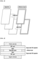
- the separator laminate for a lithium secondary battery includes a laminate in which N (however, N ⁇ 2) separators are laminated, and N-1 adhesive layers may be located between adjacent separators inside the laminate.
- each of the N-1 adhesive layers are formed along the edges of adjacent separators so as to have a separation space between the separators, respectively. More specifically, each of the N-1 adhesive layers may be in the form of a frame in which the central portion is opened, and by this type of adhesive layer, border portions of the separators adjacent to the adhesive layer may be connected and fixed to each other.
- edge of the separators and the border portion of the separators may coincide with each other.
- an adhesive layer in the form of a frame formed over the entire border portion of the separators may be formed between adjacent separators inside the separator laminate.
- the adhesive layer is formed in the form of a coating on the border portion of one-sided separator, the other-sided separators are laminated, and then dried to connect and fix the separators to each other, which is manufactured in the form of a separate adhesive film, interposed between the separators, and then laminated by applying heat, pressure, or both, so that adjacent separators can be connected and fixed to each other.
- a separator laminate in which the N (however, N ⁇ 2) separators are integrated by the N-1 adhesive layers, which can be a so-called "integrated" separator.
- the shape of the separation space formed by each of the adhesive layers is not particularly limited, and may be a polygonal shape such as a rectangular shape, or a circular shape, and may have the same or different shapes in the N-1 adhesive layers.
- the area occupied by the separation space is not particularly limited, and may be the same or different in the N-1 adhesive layers. Since each of the adhesive layers may be formed on the border portions of the separators, the area of the separation space may be determined according to the width of the border portion.
- the area occupied by the separation space is not limited, but may be 50 to 99 area%, 50 to 90 area%, 50 to 85 area%, or 50 to 80 area%, and the remaining area is occupied by the adhesive layer, so that the adjacent separators can be adhered thereto.
- the area occupied by the separation space is generally larger than that of the positive electrode and the negative electrode, it may be the same as the area of the positive electrode or the negative electrode in the electrode assembly to be described later and also manufactured later, specifically, it may be the same as the area of the negative electrode in which the metal column is grown.
- the constituent component of the adhesive layer has adhesion to the adjacent separators, and it is not particularly limited as long as it is a material of binders that does not impair battery characteristics.
- the adhesive layer may include, for example, one selected from the group consisting of polyvinylidene fluoride (PVdF), polytetrafluoroethylene (PTFE), styrene butadiene rubber (SBR), polyvinylidene fluoride-co-hexafluoropropylene, polyvinylidene fluoride-co-trichloroethylene, polymethylmethacrylate, polyacrylonitrile, polyvinylpyrrolidone, polyvinylacetate, polyethylene-co-vinyl acetate, polyimide, polyethylene oxide, cellulose acetate, cellulose acetate butyrate, cellulose acetate propionate, cyanoethylpullulan, cyanoethylpolyvinylalcohol, cyanoethylcellulose, cyanoethylsucrose, pullulan, carboxyl methyl cellulose, acrylonitrile-styrene-butadiene copoly
- the method of manufacturing the separator laminate for a lithium secondary battery according to the one embodiment is not particularly limited as long as it is a method capable of forming the above-described structure.
- the separator laminate can be manufactured by using either one of the separators as an upper separator, using another separator as a lower separator, coating the adhesive layer along the edge of the upper separator or the lower separator, then laminating the upper separator and the lower separator and drying the adhesive layer.
- the separator laminate may be manufactured by inserting an adhesive layer in the form of a film between the upper separator and the lower separator and then performing lamination.
- the edge is the same as a border portion, and means the area of the portion adjacent to the four corners of the separator.
- the specific width is the same as described above, and is a portion where the adhesive layer is formed in FIG. 1 .
- Example 2 when three separators are used as in Example 2 described later, one separator is used as the upper separator, another separator is used as the lower separator, and the other separator is used as an intermediate separator, to thereby form an adhesive layer as in the case of using the two separators so that the separators can be adhered along edges of adjacent separators.
- Electrode assembly and lithium secondary battery including same
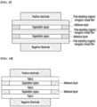
- an electrode assembly comprising: a negative electrode; a positive electrode; and the separator laminate of the above-mentioned one embodiment located between the negative electrode and the positive electrode.
- the separator laminate is larger than the area of the negative electrode and the positive electrode at four corners.
- the adhesive layer formed on the separator laminate may be formed at a portion not facing the negative electrode or the positive electrode along the edge of the separator included in the separator laminate.
- the adhesive layer When the adhesive layer is formed only in the portion not facing the negative electrode and the positive electrode in this way, it does not interfere with lithium ions of the negative electrode and the positive electrode while the separators can be adhered, and and forms a separation space between the negative electrode and the positive electrode Thus, it is easy to change the growth direction of the metal column growing from the negative electrode. More specifically, in order to provide a separation space at the growth position of the metal column grown from the negative electrode, the adhesive layer may be formed at a portion not facing the negative electrode along the edges of the separators included in the separator laminate.
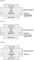
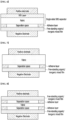
- FIGS. 2 to 12 a unit electrode assembly including a separator laminate made by bonding different types of separators by two or three is shown in FIGS. 2 to 12 .
- the types of separators included in the separator laminate can be variously combined, and the adhesive layer formed therebetween is formed between adjacent separators inside.
- the adhesive layer is formed at a portion not facing the positive electrode or the negative electrode along the edges of the separators.
- the electrode assembly may be variously implemented in a stack process, a lamination and stack process, a stack and folding process, a jelly-roll process, and a zigzag folding process, as it includes the separator laminate of the above-described one embodiment.
- the lithium secondary battery including the electrode assembly.
- the lithium secondary battery may include an electrolyte in the electrode assembly.
- the negative electrode active material may include carbons such as hardly graphitizable carbon and graphite-based carbon; metal composite oxides such as Li x Fe 2 O 3 (0 ⁇ x ⁇ 1), Li x WO 2 (0 ⁇ x ⁇ 1), Sn x Me 1-x Me' y O z (Me: Mn, Fe, Pb, Ge; Me': Al, B, P, Si, Group 1, 2, 3 elements in the periodic table, halogen; 0 ⁇ x ⁇ 1; 1 ⁇ y ⁇ 3; 1 ⁇ z ⁇ 8); lithium titanium oxide, lithium metal; lithium alloys; silicon-based alloys; tin-based alloys; metal oxides such as SnO, SnO 2 , PbO, PbO 2 , Pb 2 O 3 , Pb 3 O 4 , Sb 2 O 3 , Sb 2 O 4 , Sb 2 O 5 , GeO, GeO 2 , Bi 2 O 3 , Bi 2 O 4 , and Bi 2 O 5 ; a
- the negative electrode may be a lithium metal negative electrode including a lithium-free negative electrode (Li free anode) made of only a copper current collector; or a copper current collector; and a lithium metal layer located on the copper current collector.
- a lithium-free negative electrode Li free anode
- the binder is a component that assists in the binding between the active material and the other solids, wherein the binder may typically be added in an amount of 0.1 to 30% by weight based on the total weight of the negative electrode containing the negative electrode active material.
- the binder include polyvinylidene fluoride, polyvinylidene fluoride-hexafluoropropylene, polyvinyl alcohol, carboxymethylcellulose (CMC), starch, hydroxypropylcellulose, regenerated cellulose, polyvinylpyrrolidone, tetrafluoroethylene, polytetrafluoroethylene, polyethylene, polypropylene, an ethylene-propylene-diene terpolymer (EPDM), a sulfonated EPDM, a styrene-butadiene rubber, a fluorine rubber, various copolymers, and the like.
- the positive electrode of a lithium secondary battery may generally have a structure in which a positive electrode mixture including a positive electrode active material is formed on a positive electrode current collector.
- Li a A 1-b R b D 2 (wherein, 0.90 ⁇ a ⁇ 1.8 and 0 ⁇ b ⁇ 0.5); Li a E 1-b R b O 2-c D c (wherein, 0.90 ⁇ a ⁇ 1.8, 0 ⁇ b ⁇ 0.5, and 0 ⁇ c ⁇ 0.05); LiE 2-b R b O 4-c D c (wherein, 0 ⁇ b ⁇ 0.5, and 0 ⁇ c ⁇ 0.05); Li a Ni 1-b-c Co b R c D ⁇ (wherein, 0.90 ⁇ a ⁇ _ 1.8, 0 ⁇ b ⁇ _ 0.5, 0 ⁇ c ⁇ _ 0.05 and 0 ⁇ ⁇ ⁇ _ 2); Li a Ni 1-b-c Co b R c O 2- ⁇ Z ⁇ (wherein, 0.90 ⁇ a ⁇ 1.8, 0 ⁇ b ⁇ 0.5, 0 ⁇ c ⁇ 0.05
- A is Ni, Co, Mn or a combination thereof;
- R is Al, Ni, Co, Mn, Cr, Fe, Mg, Sr, V, a rare earth element or a combination thereof;
- D is O, F, S, P or a combination thereof;
- E is Co, Mn or a combination thereof;
- Z is F, S, P or a combination thereof;
- G is Al, Cr, Mn, Fe, Mg, La, Ce, Sr, V or a combination thereof;
- Q is Ti, Mo, Mn or a combination thereof;
- the coating layer may include a coating element compound such as coating element oxide, hydroxide, coating element oxyhydroxide, coating element oxycarbonate or coating element hydroxycarbonate.
- the compounds forming these coating layers may be amorphous or crystalline.
- a coating element included in the coating layer Mg, Al, Co, K, Na, Ca, Si, Ti, V, Sn, Ge, Ga, B, As, Zr or a mixture thereof can be used.
- any coating method can be used as long as it can be coated by a method (e.g., spray coating or dipping method, etc.) that does not adversely affect the physical properties of the positive electrode active material by using these elements in the compound. Since this is a content that may be widely understood by those worked in the art, and thus, detailed descriptions thereof will be omitted.
- the electrolyte of the lithium secondary battery may be a liquid electrolyte (i.e., an electrolyte solution) or a solid electrolyte.
- the electrolyte of the lithium secondary battery When the electrolyte of the lithium secondary battery is a liquid electrolyte, it includes a non-aqueous organic solvent and a lithium salt.
- the non-aqueous organic solvent serves as a medium capable of moving ions that are involved in an electrochemical reaction of a battery.
- the non-aqueous organic solvent may include a carbonate-based, ester-based, ether-based, ketone-based, alcohol-based, or aprotic solvent.
- Examples of the carbonate-based solvent may include dimethyl carbonate (DMC), diethyl carbonate (DEC), dipropyl carbonate (DPC), methylpropyl carbonate (MPC), ethylpropyl carbonate (EPC), methylethyl carbonate (MEC), ethylene carbonate (EC), propylene carbonate (PC), butylene carbonate (BC), and the like.
- ester-based solvent may include methyl acetate, ethyl acetate.
- ester-based solvent may include methyl acetate, ethyl acetate, n-propyl acetate, 1,1-dimethylethylacetate, methylpropionate, ethylpropionate, ⁇ -butyrolactone, decanolide, valerolactone, mevalonolactone, caprolactone, and the like.
- ether-based solvent may include 1,2-dimethoxyethane (DME), dibutyl ether, tetraglyme, diglyme, 2-methyltetrahydrofuran, tetrahydrofuran, and the like.
- Examples of the ketone-based solvent may include cyclohexanone and the like.
- Examples of the alcohol-based solvent may include ethyl alcohol, isopropyl alcohol, and the like.
- Examples of the aprotic solvent may include nitriles such as R-CN (where R is a C2 to C20 linear, branched, or cyclic hydrocarbon group, a double bond, an aromatic ring, or an ether bond), amides such as dimethylformamide, dioxolanes such as 1,3-dioxolane, sulfolane, and the like.
- the non-aqueous organic solvents may be used alone or in a mixture of two or more thereof.
- the mixing ratio thereof may be appropriately controlled according to the desired battery performance, which may be widely understood by those worked in the art.
- the carbonate-based solvent when used, it is favorable to use cyclic carbonate and chained carbonate in a mixture thereof.
- the cyclic carbonate and the chained carbonate are mixed at a volume ratio of 1:1 to 1:9, so that the performance of the electrolyte can be favorably exhibited.
- the non-aqueous organic solvent may further include an aromatic hydrocarbon-based organic solvent in addition to the carbonate-based solvent.
- the carbonate-based solvent and the aromatic hydrocarbon based organic solvent may be mixed at a volume ratio of 1:1 to 30:1.
- an aromatic hydrocarbon-based compound of the following Chemical Formula 1 may be used.
- R 1 to R 6 are each independently hydrogen, a halogen, a C1 to C10 alkyl group, a C1 to C10 haloalkyl group, or a combination thereof.
- the aromatic hydrocarbon-based organic solvent may include benzene, fluorobenzene, 1,2-difluorobenzene, 1,3-difluorobenzene, 1,4-difluorobenzene, 1,2,3-trifluorobenzene, 1,2,4-trifluorobenzene, chlorobenzene, 1,2-dichlorobenzene, 1,3-dichlorobenzene, 1,4-dichlorobenzene, 1,2,3-trichlorobenzene, 1,2,4-trichlorobenzene, iodobenzene, 1,2-diiodobenzene, 1,3-diiodobenzene, 1,4-diiodobenzene, 1,2,3-triiodobenzene, 1,2,4-triiodobenzene, toluene, fluorotoluene, 1,2-difluorotoluene, 1,3-difluorotol
- the non-aqueous electrolyte may further contain vinylene carbonate or an ethylene carbonate-based compound of the following Chemical Formula 2 in order to improve the battery lifespan:
- R 7 and R 8 are each independently hydrogen, a halogen group, a cyano group (CN), a nitro group (NO 2 ), or a C1-C5 fluoroalkyl group, and at least one of R 7 and R 8 is a halogen group, a cyano group (CN), a nitro group (NO 2 ), or a C1-C5 fluoroalkyl group.
- ethylene carbonate-based compound may include difluoroethylene carbonate, chloroethylene carbonate, dichloroethylene carbonate, bromoethylene carbonate, dibromoethylene carbonate, nitroethylene carbonate, cyanoethylene carbonate, fluoroethylene carbonate, and the like.
- the use amounts thereof may be appropriately adjusted to improve the lifetime.
- the lithium salt is dissolved in the organic solvent to act as a lithium ion supply source in the battery, thereby enabling a basic operation of a lithium secondary battery of one embodiment and promoting the movement of lithium ions between a positive electrode and a negative electrode.
- lithium salt a lithium salt widely applied to an electrolyte may be generally used.
- LiFSI lithium bis(fluorosulfonyl)imide
- LiPF 6 LiBF 4 , LiSbF 6 , LiAsF 6 , LiC 4 F 9 SO 3 , LiClO 4 , LiAlO 2 , LiAlCl 4 , LiN(C x F 2x+1 SO 2 )(C y F 2y+1 SO 2 ) (where, x and y are a natural number)
- LiCl, LiI, LiB(C 2 O 4 ) 2 (lithium bis(oxalato)borate; LiBOB) or a combination thereof may be used, without being limited thereto.
- the concentration of the lithium salt may be controlled within the range of 0.1 to 5.0M. Within this range, the electrolytes can have adequate conductivity and viscosity, so that the lithium ions can be effectively moved within the lithium secondary battery of the one embodiment.
- this is merely an example, and the present disclosure is not limited thereto.
- the electrolyte of the lithium secondary battery is a solid electrolyte
- the solid electrolyte that can be used is not particularly limited.
- Two polyethylene substrates (width*length*thickness: 40mm*60mm*5um, porosity 40%) were prepared, and a coating layer was formed on each surface using a dip coating method.
- a high-concentration ether-based electrolyte (3.5M LiFSI in DME) was used to evaluate a 2Ah stack cell.
- 3.5M LiFSI lithium bis(fluorosulfonyl)imide
- DME 1,2-dimethoxyethane
- separator laminate of Example 2 a separator laminate having a structure of [single-sided SRS separator/adhesive layer/polyethylene fabric/adhesive layer/single-sided SRS separator] was finally obtained, which was referred to as the separator laminate of Example 2.
- One polyethylene substrate (width*length*thickness: 40mm*60mm*5um, porosity 40%) was prepared and used as a substrate.
- Coating layers were formed on both sides of the substrate. Specifically, in the same coating solution as in Example 1, the entire surface of the substrate was immersed for 3 minutes and then taken out, and dried at 80°C for 60 minutes.
- a lithium secondary battery was manufactured in the same manner as in Example 1, except that the separator laminate of Comparative Example 1 was used instead of the separator laminate of Example 1.
- a single-sided SRS separator was prepared in the same manner as in Example 1, and then simply laminated without an adhesive film to manufacture a separator having a structure of [single-side SRS separator / single-sided SRS separator].
- a lithium secondary battery was manufactured in the same manner as in Example 1, except that the separator of Comparative Example 2 was used instead of the separator of Example 1.
- a single-sided SRS separator was prepared in the same manner as in Example 1, and then simply laminated without an adhesive film using the polyethylene substrate of Example 2 to manufacture a separator having a structure of [single-sided SRS separator/polyethylene fabric/single-side SRS separator] .
- a lithium secondary battery was manufactured in the same manner as in Example 1, except that the separator of Comparative Example 3 was used instead of the separator of Example 1.
- Each of the separator laminates of Examples 1 to 2 and Comparative Example 1 was assembled in a stack-and-folding process, thereby enabling driving as a lithium secondary battery.
- each of the separator laminates of Comparative Examples 2 and 3 could not be implemented as an electrode assembly including lamination such as stack & folding and lamination & folding.
- each of the separators of Comparative Examples 2 and 3 included two or more separators, but adjacent separators were independently separated, and a large number of mismatches occurred, and thus could not be implemented as the electrode assembly including lamination.
- each of the separators of Comparative Examples 2 and 3 was assembled in the form of a coin cell commonly known in the art, and implemented as a lithium secondary battery.
- the discharge capacity according to the charge/discharge cycle of each lithium battery was normalized to the discharge capacity of the first cycle, and the results are shown in FIG. 2 .
- each of the separator laminates of Examples 1 to 2 may be implemented as an electrode structure including lamination such as stack & folding as well as lamination & folding. This is because each of the separator laminates of Examples 1 to 2 includes two or more substrates, but an adhesive film is inserted each between adjacent substrates to form an integrated separator.
- the adhesive film is in contact with only the border portions of adjacent separators, thus partially leaving a separation space between adjacent separators.
- the separation space between adjacent separators induces a change in the growth direction of the metal column, inhibits micro-short circuit and ultimately secure the life of the battery.
- each of the separator laminates of Examples 1 to 2 even if the lower separator is pierced by a metal column grown toward the positive electrode from the surface of the negative electrode, the metal column whose growth direction is changed is made to grow horizontally in the separation space between separators when the growth of the metal column is blocked by the intermediate separator (Example 2) or the upper separator (Examples 1 and 2), thereby inhibiting micro-short circuit.
- the separator of Comparative Example 1 can be implemented as an electrode structure including lamination, such as stack & folding and lamination & folding.
- an SRS separator in which an adjacent substrate and a coating layer are integrally formed does not have a structure in which a separation space is formed between the two separators, and thus, it is not possible to induce a change in the growth direction of the metal column grown from the negative electrode, and it is not possible to inhibit micro-short circuit of the lithium secondary battery to which this is applied.
- the lithium secondary battery of Comparative Example 1 that was driven according to Experimental Example 1 allowed to stop at the 14th cycle and then decomposed to recover the separator.
- the separator of Comparative Example 1 thus recovered was photographed with a digital camera and a digital microscope (Dino-Lite Digital Microscope), respectively, and each photographed image is shown in FIGS. 13a and 13b .
- the both surfaces were separated based on the center of thickness, photographed with a digital camera, and shown in FIG. 13a .
- the order from left to right of FIG. 13a of the both sides of the recovered separator, it corresponds to the outside and inside of the surface in contact with the negative electrode, and the inside and outside of the surface in contact with the positive electrode.
- FIG. 13b is a photograph of a metal column embedded in the inside of the surface in contact with the positive electrode among both sides of the recovered separator, taken with a digital microscope.
- the double-sided SRS separator of Comparative Example 1 has only one substrate, so it is vulnerable to attack by metal columns grown from the negative electrode, and is a structure in which between the upper coating layer and the substrate, and between the upper coating layer and the substrate, are attached without any gaps, respectively, and thus, it is possible to know that there is no room for the growth direction of the metal column to change.
- the lithium secondary battery of Example 1 that was driven according to Experimental Example 1 allowed to stop at the 46th cycle (when the capacity retention rate reached 80%), and then decomposed to recover the separator.
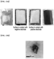
- the separator laminate of Example 1 thus recovered was photographed with a digital camera, and the photographed image is shown in FIGS. 14a and 14b .
- Example 2 which was driven according to Experimental Example 1, was stopped in a fully charged state at the 41st cycle (when the capacity retention reached 80%), and then decomposed to recover the separator.
- the separator laminate of Example 2 thus recovered was photographed with a digital camera, and the photographed image is shown in FIG. 15 .
- the both surfaces were separated based on the intermediate separator, then photographed with a digital camera and shown in FIG. 15 .
- FIG. 15 In the order from left to right of FIG. 15 , in the both sides of the recovered separator, it corresponds to the outside and inside of the surface in contact with the negative electrode, and the inside and outside of the surface in contact with the positive electrode.
- the thickness of the separator is partially thickened by a structure in which three separators are laminated, the thickness of the separator is partially thickened, and thus has excellent mechanical strength, as compared with the case of using one separator of Comparative Example 1.
Landscapes
- Chemical & Material Sciences (AREA)
- Chemical Kinetics & Catalysis (AREA)
- Electrochemistry (AREA)
- General Chemical & Material Sciences (AREA)
- Engineering & Computer Science (AREA)
- Materials Engineering (AREA)
- Manufacturing & Machinery (AREA)
- Inorganic Chemistry (AREA)
- Composite Materials (AREA)
- Secondary Cells (AREA)
- Cell Separators (AREA)
Applications Claiming Priority (4)
| Application Number | Priority Date | Filing Date | Title |
|---|---|---|---|
| KR20190060051 | 2019-05-22 | ||
| KR1020200056953A KR102834337B1 (ko) | 2019-05-22 | 2020-05-13 | 리튬 이차 전지용 분리막 적층체, 이를 포함하는 전극 조립체 및 리튬 이차 전지 |
| PCT/KR2020/006716 WO2020235969A1 (ko) | 2019-05-22 | 2020-05-22 | 리튬 이차 전지용 분리막 적층체, 이를 포함하는 전극 조립체 및 리튬 이차 전지 |
| EP20808773.4A EP3923372A4 (de) | 2019-05-22 | 2020-05-22 | Separatorstapelkörper für lithium-sekundärbatterie sowie elektrodenanordnung und lithiumsekundärbatterie damit |
Related Parent Applications (1)
| Application Number | Title | Priority Date | Filing Date |
|---|---|---|---|
| EP20808773.4A Division EP3923372A4 (de) | 2019-05-22 | 2020-05-22 | Separatorstapelkörper für lithium-sekundärbatterie sowie elektrodenanordnung und lithiumsekundärbatterie damit |
Publications (2)
| Publication Number | Publication Date |
|---|---|
| EP4513655A2 true EP4513655A2 (de) | 2025-02-26 |
| EP4513655A3 EP4513655A3 (de) | 2025-05-21 |
Family
ID=73459411
Family Applications (2)
| Application Number | Title | Priority Date | Filing Date |
|---|---|---|---|
| EP20808773.4A Pending EP3923372A4 (de) | 2019-05-22 | 2020-05-22 | Separatorstapelkörper für lithium-sekundärbatterie sowie elektrodenanordnung und lithiumsekundärbatterie damit |
| EP24221530.9A Pending EP4513655A3 (de) | 2019-05-22 | 2020-05-22 | Separatorlaminat für lithiumsekundärbatterie, elektrodenanordnung damit und lithiumsekundärbatterie damit |
Family Applications Before (1)
| Application Number | Title | Priority Date | Filing Date |
|---|---|---|---|
| EP20808773.4A Pending EP3923372A4 (de) | 2019-05-22 | 2020-05-22 | Separatorstapelkörper für lithium-sekundärbatterie sowie elektrodenanordnung und lithiumsekundärbatterie damit |
Country Status (4)
| Country | Link |
|---|---|
| US (1) | US12266822B2 (de) |
| EP (2) | EP3923372A4 (de) |
| JP (1) | JP7276970B2 (de) |
| WO (1) | WO2020235969A1 (de) |
Families Citing this family (8)
| Publication number | Priority date | Publication date | Assignee | Title |
|---|---|---|---|---|
| US20210135202A1 (en) * | 2019-10-30 | 2021-05-06 | National Taiwan University Of Science And Technology | Composite layer and lithium-based battery having the same |
| JP7409348B2 (ja) * | 2021-04-15 | 2024-01-09 | トヨタ自動車株式会社 | ハニカム型リチウムイオン電池 |
| CN113314801B (zh) * | 2021-05-21 | 2022-08-30 | 中南大学 | 缓释型功能性隔膜及其制备方法、锂电池 |
| CN115832605B (zh) * | 2021-12-01 | 2023-10-10 | 宁德时代新能源科技股份有限公司 | 隔膜、电池、电池模块、电池包和用电装置 |
| KR102918604B1 (ko) * | 2022-11-18 | 2026-01-26 | 주식회사 엘지화학 | 리튬 이차 전지 |
| CN118738510A (zh) * | 2023-03-29 | 2024-10-01 | 本田技研工业株式会社 | 二次电池及其制造方法 |
| WO2025070647A1 (ja) * | 2023-09-29 | 2025-04-03 | パナソニックIpマネジメント株式会社 | 非水電解質二次電池 |
| WO2025070646A1 (ja) * | 2023-09-29 | 2025-04-03 | パナソニックIpマネジメント株式会社 | リチウム二次電池 |
Citations (1)
| Publication number | Priority date | Publication date | Assignee | Title |
|---|---|---|---|---|
| KR20090018123A (ko) | 2006-06-08 | 2009-02-19 | 쓰리엠 이노베이티브 프로퍼티즈 캄파니 | 수-기재의 폴리우레탄 바닥 코팅 조성물 |
Family Cites Families (31)
| Publication number | Priority date | Publication date | Assignee | Title |
|---|---|---|---|---|
| KR100389123B1 (ko) | 1995-01-27 | 2003-09-29 | 삼성전자주식회사 | 알카리2차전지용 세퍼레이터 및 이의 제조방법 |
| KR100670429B1 (ko) | 2005-11-29 | 2007-01-16 | 삼성에스디아이 주식회사 | 리튬 이차 전지 |
| JP2008016193A (ja) | 2006-06-30 | 2008-01-24 | Mitsui Mining & Smelting Co Ltd | 非水電解液二次電池の製造方法 |
| JP5125256B2 (ja) | 2007-06-27 | 2013-01-23 | トヨタ自動車株式会社 | 燃料電池用セパレータの製造方法、燃料電池用セパレータ及び燃料電池 |
| KR101308248B1 (ko) | 2007-09-14 | 2013-09-13 | 삼성에스디아이 주식회사 | 캔형 리튬 이차 전지 |
| JP2010073505A (ja) | 2008-09-19 | 2010-04-02 | Fuji Electric Systems Co Ltd | 端部シール部材の製造方法、端部シール部材、燃料電池の製造方法及び燃料電池 |
| CN201340888Y (zh) | 2009-01-08 | 2009-11-04 | 东莞新能源科技有限公司 | 锂离子电池 |
| JP5235715B2 (ja) * | 2009-02-25 | 2013-07-10 | 富士重工業株式会社 | 蓄電デバイスおよびその製造方法 |
| KR101090684B1 (ko) | 2009-07-16 | 2011-12-08 | 에스케이이노베이션 주식회사 | 전지용 전극조립체 및 그 제조방법 |
| JP5586044B2 (ja) | 2010-02-10 | 2014-09-10 | Necエナジーデバイス株式会社 | 積層型二次電池 |
| WO2012042779A1 (ja) * | 2010-09-28 | 2012-04-05 | パナソニック株式会社 | 非水電解質二次電池及びその製造方法 |
| JP5798346B2 (ja) * | 2011-03-20 | 2015-10-21 | 国立大学法人信州大学 | セパレーターの製造方法 |
| JP5704405B2 (ja) * | 2011-11-15 | 2015-04-22 | トヨタ自動車株式会社 | 二次電池 |
| KR101557302B1 (ko) | 2012-11-21 | 2015-10-05 | 주식회사 엘지화학 | 이종 분리막들을 포함하고 있는 전극조립체 및 이를 포함하는 이차전지 |
| JP2015046325A (ja) | 2013-08-28 | 2015-03-12 | 株式会社Gsユアサ | 蓄電素子 |
| EP3090455B1 (de) * | 2014-01-02 | 2020-01-15 | Daramic, Llc | Mehrschichtiger separator |
| CN106463779B (zh) * | 2014-04-09 | 2019-02-26 | Nec 能源元器件株式会社 | 锂离子二次电池 |
| JP2016081668A (ja) | 2014-10-15 | 2016-05-16 | 株式会社日本自動車部品総合研究所 | 二次電池 |
| JP6511694B6 (ja) * | 2014-11-27 | 2019-06-12 | 株式会社エンビジョンAescエナジーデバイス | 電池 |
| JP6511693B6 (ja) * | 2014-11-27 | 2019-06-12 | 株式会社エンビジョンAescエナジーデバイス | 電池 |
| JP2016207649A (ja) * | 2015-04-15 | 2016-12-08 | 東レ株式会社 | 電池用セパレータおよび電池 |
| KR20160146125A (ko) | 2015-06-11 | 2016-12-21 | 현대자동차주식회사 | 다층구조의 리튬이차전지용 분리막 및 이를 이용한 리튬이차전지 |
| JP2017130301A (ja) * | 2016-01-19 | 2017-07-27 | パナソニック株式会社 | 非水電解質二次電池及び非水電解質二次電池の製造方法 |
| KR20170098578A (ko) * | 2016-02-22 | 2017-08-30 | 대관령신용협동조합 | 즉석 황태 미역국용 식재료 조성물 및 이를 이용한 황태 미역국 제조방법 |
| JP2017152284A (ja) * | 2016-02-26 | 2017-08-31 | パナソニック株式会社 | 袋状セパレータ及び非水電解質二次電池 |
| US20200052278A1 (en) | 2017-03-31 | 2020-02-13 | Envision Aesc Energy Devices Ltd. | Method for bonding separators, method for manufacturing electrochemical device, and electrochemical device |
| KR102140127B1 (ko) | 2017-04-25 | 2020-07-31 | 주식회사 엘지화학 | 리튬 이차전지용 음극, 이의 제조방법 및 이것을 포함하는 리튬 이차전지 |
| KR102612838B1 (ko) | 2017-08-03 | 2023-12-13 | 데이진 가부시키가이샤 | 비수계 이차전지용 세퍼레이터, 및 비수계 이차전지 |
| CN110832672B (zh) | 2017-10-20 | 2023-05-05 | 株式会社Lg新能源 | 隔板以及包括该隔板的电化学装置 |
| CN208226003U (zh) | 2018-04-13 | 2018-12-11 | 宁德新能源科技有限公司 | 电池及其电子设备 |
| CN113196558A (zh) * | 2018-08-17 | 2021-07-30 | 达拉米克有限责任公司 | 改进的铅酸电池隔板、抗翘曲隔板、电池、系统及相关方法 |
-
2020
- 2020-05-22 WO PCT/KR2020/006716 patent/WO2020235969A1/ko not_active Ceased
- 2020-05-22 JP JP2021545449A patent/JP7276970B2/ja active Active
- 2020-05-22 EP EP20808773.4A patent/EP3923372A4/de active Pending
- 2020-05-22 US US17/441,444 patent/US12266822B2/en active Active
- 2020-05-22 EP EP24221530.9A patent/EP4513655A3/de active Pending
Patent Citations (1)
| Publication number | Priority date | Publication date | Assignee | Title |
|---|---|---|---|---|
| KR20090018123A (ko) | 2006-06-08 | 2009-02-19 | 쓰리엠 이노베이티브 프로퍼티즈 캄파니 | 수-기재의 폴리우레탄 바닥 코팅 조성물 |
Also Published As
| Publication number | Publication date |
|---|---|
| JP7276970B2 (ja) | 2023-05-18 |
| US20220166109A1 (en) | 2022-05-26 |
| EP3923372A4 (de) | 2022-04-13 |
| EP4513655A3 (de) | 2025-05-21 |
| WO2020235969A1 (ko) | 2020-11-26 |
| EP3923372A1 (de) | 2021-12-15 |
| US12266822B2 (en) | 2025-04-01 |
| JP2022519361A (ja) | 2022-03-23 |
Similar Documents
| Publication | Publication Date | Title |
|---|---|---|
| US12266822B2 (en) | Separator laminate for lithium secondary battery, electrode assembly including the same, and lithium secondary battery including the same | |
| EP2624333B1 (de) | Lithium-Sekundärbatterie | |
| EP2584628B1 (de) | Lithium Sekundärbatterie | |
| KR100913176B1 (ko) | 리튬 이차 전지용 음극 및 이를 포함하는 리튬 이차 전지 | |
| EP2639854B1 (de) | Abscheider für Lithiumsekundärbatterie | |
| KR20200004755A (ko) | 리튬 금속 전지용 음극, 이의 제조 방법, 및 이를 포함하는 리튬 금속 전지 | |
| EP2822058B1 (de) | Lithiumbeutelbatterie | |
| US20190355952A1 (en) | Electrode assembly, method for producing same, and secondary battery including same | |
| US11355815B2 (en) | Separator for rechargeable lithium battery, and method for preparing the same, and rechargeable lithium battery including the same | |
| KR20130091174A (ko) | 리튬 이차 전지의 제조 방법 | |
| KR102383074B1 (ko) | 이차 전지용 세퍼레이터, 이의 제조방법 및 이를 포함하는 리튬 이차 전지 | |
| US12347853B2 (en) | Method for manufacturing negative electrode for lithium secondary battery | |
| KR20130090724A (ko) | 리튬 이차 전지 | |
| KR102834337B1 (ko) | 리튬 이차 전지용 분리막 적층체, 이를 포함하는 전극 조립체 및 리튬 이차 전지 | |
| EP3817095B1 (de) | Separator für lithiumsekundärbatterie, verfahren zu dessen herstellung und lithiumsekundärbatterie diesen enthaltend | |
| KR20220069809A (ko) | 리튬프리 이차전지 |
Legal Events
| Date | Code | Title | Description |
|---|---|---|---|
| PUAI | Public reference made under article 153(3) epc to a published international application that has entered the european phase |
Free format text: ORIGINAL CODE: 0009012 |
|
| STAA | Information on the status of an ep patent application or granted ep patent |
Free format text: STATUS: REQUEST FOR EXAMINATION WAS MADE |
|
| 17P | Request for examination filed |
Effective date: 20241219 |
|
| AC | Divisional application: reference to earlier application |
Ref document number: 3923372 Country of ref document: EP Kind code of ref document: P |
|
| AK | Designated contracting states |
Kind code of ref document: A2 Designated state(s): AL AT BE BG CH CY CZ DE DK EE ES FI FR GB GR HR HU IE IS IT LI LT LU LV MC MK MT NL NO PL PT RO RS SE SI SK SM TR |
|
| REG | Reference to a national code |
Ref country code: DE Ref legal event code: R079 Free format text: PREVIOUS MAIN CLASS: H01M0050489000 Ipc: H01M0010052000 |
|
| PUAL | Search report despatched |
Free format text: ORIGINAL CODE: 0009013 |
|
| AK | Designated contracting states |
Kind code of ref document: A3 Designated state(s): AL AT BE BG CH CY CZ DE DK EE ES FI FR GB GR HR HU IE IS IT LI LT LU LV MC MK MT NL NO PL PT RO RS SE SI SK SM TR |
|
| RIC1 | Information provided on ipc code assigned before grant |
Ipc: H01M 50/489 20210101ALI20250415BHEP Ipc: H01M 50/457 20210101ALI20250415BHEP Ipc: H01M 50/451 20210101ALI20250415BHEP Ipc: H01M 50/449 20210101ALI20250415BHEP Ipc: H01M 50/446 20210101ALI20250415BHEP Ipc: H01M 50/417 20210101ALI20250415BHEP Ipc: H01M 10/052 20100101AFI20250415BHEP |
|
| STAA | Information on the status of an ep patent application or granted ep patent |
Free format text: STATUS: EXAMINATION IS IN PROGRESS |
|
| 17Q | First examination report despatched |
Effective date: 20251208 |