EP4513652A1 - Separator und herstellungsverfahren dafür, sekundärbatterie mit dem separator und elektrische vorrichtung - Google Patents
Separator und herstellungsverfahren dafür, sekundärbatterie mit dem separator und elektrische vorrichtung Download PDFInfo
- Publication number
- EP4513652A1 EP4513652A1 EP22942112.8A EP22942112A EP4513652A1 EP 4513652 A1 EP4513652 A1 EP 4513652A1 EP 22942112 A EP22942112 A EP 22942112A EP 4513652 A1 EP4513652 A1 EP 4513652A1
- Authority
- EP
- European Patent Office
- Prior art keywords
- base film
- separator
- porous base
- inorganic particle
- inorganic
- Prior art date
- Legal status (The legal status is an assumption and is not a legal conclusion. Google has not performed a legal analysis and makes no representation as to the accuracy of the status listed.)
- Pending
Links
Images


Classifications
-
- H—ELECTRICITY
- H01—ELECTRIC ELEMENTS
- H01M—PROCESSES OR MEANS, e.g. BATTERIES, FOR THE DIRECT CONVERSION OF CHEMICAL ENERGY INTO ELECTRICAL ENERGY
- H01M50/00—Constructional details or processes of manufacture of the non-active parts of electrochemical cells other than fuel cells, e.g. hybrid cells
- H01M50/40—Separators; Membranes; Diaphragms; Spacing elements inside cells
- H01M50/403—Manufacturing processes of separators, membranes or diaphragms
-
- H—ELECTRICITY
- H01—ELECTRIC ELEMENTS
- H01M—PROCESSES OR MEANS, e.g. BATTERIES, FOR THE DIRECT CONVERSION OF CHEMICAL ENERGY INTO ELECTRICAL ENERGY
- H01M50/00—Constructional details or processes of manufacture of the non-active parts of electrochemical cells other than fuel cells, e.g. hybrid cells
- H01M50/40—Separators; Membranes; Diaphragms; Spacing elements inside cells
- H01M50/409—Separators, membranes or diaphragms characterised by the material
- H01M50/411—Organic material
- H01M50/414—Synthetic resins, e.g. thermoplastics or thermosetting resins
- H01M50/417—Polyolefins
-
- H—ELECTRICITY
- H01—ELECTRIC ELEMENTS
- H01M—PROCESSES OR MEANS, e.g. BATTERIES, FOR THE DIRECT CONVERSION OF CHEMICAL ENERGY INTO ELECTRICAL ENERGY
- H01M50/00—Constructional details or processes of manufacture of the non-active parts of electrochemical cells other than fuel cells, e.g. hybrid cells
- H01M50/40—Separators; Membranes; Diaphragms; Spacing elements inside cells
- H01M50/409—Separators, membranes or diaphragms characterised by the material
- H01M50/431—Inorganic material
- H01M50/434—Ceramics
-
- H—ELECTRICITY
- H01—ELECTRIC ELEMENTS
- H01M—PROCESSES OR MEANS, e.g. BATTERIES, FOR THE DIRECT CONVERSION OF CHEMICAL ENERGY INTO ELECTRICAL ENERGY
- H01M50/00—Constructional details or processes of manufacture of the non-active parts of electrochemical cells other than fuel cells, e.g. hybrid cells
- H01M50/40—Separators; Membranes; Diaphragms; Spacing elements inside cells
- H01M50/409—Separators, membranes or diaphragms characterised by the material
- H01M50/446—Composite material consisting of a mixture of organic and inorganic materials
-
- H—ELECTRICITY
- H01—ELECTRIC ELEMENTS
- H01M—PROCESSES OR MEANS, e.g. BATTERIES, FOR THE DIRECT CONVERSION OF CHEMICAL ENERGY INTO ELECTRICAL ENERGY
- H01M50/00—Constructional details or processes of manufacture of the non-active parts of electrochemical cells other than fuel cells, e.g. hybrid cells
- H01M50/40—Separators; Membranes; Diaphragms; Spacing elements inside cells
- H01M50/409—Separators, membranes or diaphragms characterised by the material
- H01M50/449—Separators, membranes or diaphragms characterised by the material having a layered structure
- H01M50/451—Separators, membranes or diaphragms characterised by the material having a layered structure comprising layers of only organic material and layers containing inorganic material
-
- H—ELECTRICITY
- H01—ELECTRIC ELEMENTS
- H01M—PROCESSES OR MEANS, e.g. BATTERIES, FOR THE DIRECT CONVERSION OF CHEMICAL ENERGY INTO ELECTRICAL ENERGY
- H01M50/00—Constructional details or processes of manufacture of the non-active parts of electrochemical cells other than fuel cells, e.g. hybrid cells
- H01M50/40—Separators; Membranes; Diaphragms; Spacing elements inside cells
- H01M50/409—Separators, membranes or diaphragms characterised by the material
- H01M50/449—Separators, membranes or diaphragms characterised by the material having a layered structure
- H01M50/457—Separators, membranes or diaphragms characterised by the material having a layered structure comprising three or more layers
-
- H—ELECTRICITY
- H01—ELECTRIC ELEMENTS
- H01M—PROCESSES OR MEANS, e.g. BATTERIES, FOR THE DIRECT CONVERSION OF CHEMICAL ENERGY INTO ELECTRICAL ENERGY
- H01M50/00—Constructional details or processes of manufacture of the non-active parts of electrochemical cells other than fuel cells, e.g. hybrid cells
- H01M50/40—Separators; Membranes; Diaphragms; Spacing elements inside cells
- H01M50/489—Separators, membranes, diaphragms or spacing elements inside the cells, characterised by their physical properties, e.g. swelling degree, hydrophilicity or shut down properties
-
- Y—GENERAL TAGGING OF NEW TECHNOLOGICAL DEVELOPMENTS; GENERAL TAGGING OF CROSS-SECTIONAL TECHNOLOGIES SPANNING OVER SEVERAL SECTIONS OF THE IPC; TECHNICAL SUBJECTS COVERED BY FORMER USPC CROSS-REFERENCE ART COLLECTIONS [XRACs] AND DIGESTS
- Y02—TECHNOLOGIES OR APPLICATIONS FOR MITIGATION OR ADAPTATION AGAINST CLIMATE CHANGE
- Y02E—REDUCTION OF GREENHOUSE GAS [GHG] EMISSIONS, RELATED TO ENERGY GENERATION, TRANSMISSION OR DISTRIBUTION
- Y02E60/00—Enabling technologies; Technologies with a potential or indirect contribution to GHG emissions mitigation
- Y02E60/10—Energy storage using batteries
Definitions
- the present application belongs to the technical field of secondary batteries, and in particular relates to a separator, a preparation method therefor, a secondary battery containing same, and a power consuming device.
- Secondary batteries are widely used in various consumer electronic products and electric vehicles due to their outstanding features, such as a light weight, no pollution and no memory effect.
- the energy density or capacity of secondary batteries is designed to be higher and higher; however, the increase in the energy density or capacity of the battery is often detrimental to balancing a dynamic performance, electrochemical performance, or safety performance, etc.
- the present application provides a separator, which aims to enable a secondary battery comprising the separator to have a relatively good capacity performance and safety performance.
- the present application provides a separator, comprising: a first porous base film;
- the intermediate layer of the separator of the present application comprises the inorganic phase and the organic phase into which the inorganic phase is embedded, the first porous base film and the second porous base film are connected by means of the organic phase, such that the layers of the separator have a good bonding therebetween, and the compounding of the inorganic particle and the porous base films may be realized without adding a binder.
- the layers of the separator have a relatively high bonding therebetween, such that the thermal stability of the separator may be improved.
- the added inorganic particle may improve the wettability with an electrolyte solution, improve the thermal shrinkage of the separator, further absorb an impurity ion in the electrolyte solution, be subjected to a redox reaction with a lithium dendrite or a sodium dendrite, and then consume the lithium dendrite produced by lithium precipitation or lithium deposition on a surface of a negative electrode, and thus effectively improve a safety performance of a battery.
- the separator may avoid a problem of impedance increase brought by the binder, and thus greatly reduce an impedance of a secondary battery.
- the inorganic particle is arranged in the intermediate layer, which may further effectively reduce the contact between the inorganic particle and a surface of an electrode, reduce an unnecessary lithium consumption, improve a coulombic efficiency, reduce a capacity loss, and thus effectively improve a capacity performance of the battery.
- the organic phase of the intermediate layer contains a base film material and does not contain a binder. Therefore, the problems of poorer reaction kinetics such as an increased impedance brought by the binder may be avoided, and the problem that an inorganic particle cannot effectively react with a lithium dendrite or a sodium dendrite due to the fact that the binder coats the inorganic particle may be avoided.
- the separator is used in a secondary battery, the impedance of the secondary battery may be greatly reduced, and the capacity performance and safety performance of the battery are effectively improved.
- the organic phase forms a continuous phase with a material of the first porous base film and/or a material of the second porous base film; and optionally, the organic phase penetrates the inorganic phase in the thickness direction of the intermediate layer. Therefore, the bonding between the layers of the separator may be further improved, and thus the thermal stability of the separator may be improved.
- the inorganic particle is selected from at least one of an Al oxide, an Al nitride, an Al fluoride, an Si oxide, an Si nitride, an Si fluoride, an Fe oxide, an Fe nitride, an Fe fluoride, an Fe oxysalt, a Ti oxide, a Ti nitride, a Ti fluoride, a Co oxide, a Co nitride, a Co fluoride, an Ni oxide, an Ni nitride, an Ni fluoride, an Mn oxide, an Mn nitride, an Mn fluoride, an Sn oxide, an Sn nitride, an Sn fluoride, and ZnO.
- the inorganic particle is capable of being subjected to a redox reaction
- the inorganic particle comprises a hydroxyl group and/or a carboxyl group.
- the inorganic particle has a conductivity of ⁇ 1 ⁇ 10 -1 mS/cm, optionally ⁇ 1 ⁇ 10 -5 mS/cm.
- a thickness of the intermediate layer is 8%-90% of a total thickness of the separator, optionally 9%-50%.
- the intermediate layer has a thickness of 0.5-10 ⁇ m, optionally 2-7 ⁇ m;
- the inorganic particle has a Dv50 particle size greater than an average pore size of the first porous base film and/or an average pore size of the second porous base film.
- the Dv50 particle size of the inorganic particle is 105%-1,000% of the average pore size of the first porous base film and the second porous base film, optionally 105%-600%.
- the Dv50 particle size of the inorganic particle is ⁇ 100 nm, optionally 100 nm-5 ⁇ m, preferably 200 nm-2 ⁇ m; and/or the average pore size of the first porous base film and the second porous base film is ⁇ 150 nm, optionally 10-200 nm, preferably 10-100 nm.
- the Dv50 particle size of the inorganic particle is controlled within the given range, it is helpful to improve the bonding between the layers of the separator and the wettability with an electrolyte solution, thereby further improving the capacity performance of the battery.
- the intermediate layer consists of the inorganic phase and the organic phase;
- a material of the first porous base film, a material of the second porous base film, and the base film material are each independently selected from at least one of polyethylene, polypropylene, polyvinylidene fluoride, aramid, polyethylene terephthalate, polytetrafluoroethylene, polyacrylonitrile, polyimide, polyamide, polyester, and natural fiber; and optionally, the base film material is the same as or different from the material of the first porous base film and/or the material of the second porous base film.
- the inorganic particle has a Dv50 particle size greater than an average pore size of the first porous base film and/or an average pore size of the second porous base film.
- the present application provides a method for preparing a separator, comprising the following steps:
- the present application further provides another method for preparing a separator, comprising the following steps:
- the present application provides a secondary battery, comprising the separator according to the first aspect of the present application or the separator prepared by the method according to the second aspect of the present application.
- the present application provides a power consuming device, comprising the secondary battery according to the third aspect of the present application.
- any lower limit may be combined with any upper limit to form a range that is not explicitly described; and any lower limit may be combined with any other lower limit to form a range that is not explicitly specified, and any upper limit likewise may be combined with any other upper limit to form a range that is not explicitly specified.
- each individually disclosed point or single value itself may serve as a lower or upper limit in combination with any other point or single value or with other lower or upper limit to form a range that is not explicitly specified.
- the term "or” is inclusive. That is to say, the phrase “A or B” means “A, B, or both A and B". More specifically, the condition “A or B” is satisfied by any one of the following: A is true (or present) and B is false (or not present); A is false (or not present) and B is true (or present); or both A and B are true (or present).
- the terms used in the present application have the meaning well-known to a person of ordinary skill in the art.
- the values of the parameters mentioned in the present application may be measured by various measurement methods commonly used in the art (for example, may be measured according to the method illustrated in the examples of the present application).
- a secondary battery refers to a battery which can continue to be used by activating an active material by means of charging after the battery is discharged.
- the secondary battery comprises a positive electrode plate, a negative electrode plate, a separator and an electrolyte.
- an active ion is intercalated and deintercalated back and forth between the positive electrode plate and the negative electrode plate.
- the separator is arranged between the positive electrode plate and the negative electrode plate, and functions for separation.
- the electrolyte functions to conduct an ion between the positive electrode plate and the negative electrode plate.
- a traditional separator has a poor electrolyte solution wettability.
- a separator such as polypropylene (PP) and polyethylene (PE), has a lower pore closing temperature, a poor thermal shrinkage performance, and a serious safety problem.
- Some techniques attempt to introduce an inorganic material into a separator by means of bonding with a binder. However, since the binder has a relatively poor ionic conductivity, the binder will obviously increase an impedance of a battery and reduce a discharge power. In addition, where lithium is continuously precipitated or a lithium dendrite has been produced in a secondary battery, the separator is easily pierced, which causes a safety problem.
- Some techniques apply a substance, which is capable of eliminating lithium, near a negative electrode side to consume lithium.
- the separator provided in the present application comprises: a first porous base film, a second porous base film, and an intermediate layer.
- the intermediate layer comprises an inorganic phase and an organic phase into which the inorganic phase is embedded, the inorganic phase contains an inorganic particle, the organic phase connects the first porous base film with the second porous base film, and the organic phase contains a base film material and does not contain a binder.
- Fig. 2 shows a scanning electron microscope (SEM) picture of a cross section of a separator of an example of the present application. It may be seen from Fig. 2 that the separator comprises a first porous base film 61, a second porous base film 62, and an intermediate layer 63.
- the first porous base film 61, the second porous base film 62, and the intermediate layer 63 are stacked.
- the intermediate layer 62 comprises an inorganic phase 631 and an organic phase 632 into which the inorganic phase 631 is embedded, the inorganic phase 631 contains an inorganic particle, the organic phase 632 connects the first porous base film 61 with the second porous base film 62, and the organic phase contains a base film material and does not contain a binder.
- the added inorganic particle may improve the wettability with an electrolyte solution, improve the thermal shrinkage of the separator, further absorb an impurity ion in the electrolyte solution, be subjected to a redox reaction with a lithium dendrite or a sodium dendrite, and then consume the lithium dendrite produced by lithium precipitation or lithium deposition on a surface of a negative electrode, and thus effectively improve a safety performance of a battery.
- the separator may avoid a problem of impedance increase brought by the binder, and thus greatly reduce an impedance of a secondary battery.
- the inorganic particle is arranged in the intermediate layer, which may further effectively reduce the contact between the inorganic particle and a surface of an electrode, reduce an unnecessary lithium consumption, improve a coulombic efficiency, reduce a capacity loss, and thus effectively improve a capacity performance of the battery.
- the organic phase of the intermediate layer contains a base film material and does not contain a binder. Therefore, the problems of poorer reaction kinetics such as an increased impedance brought by the binder may be avoided, and the problem that an inorganic particle cannot effectively react with a lithium dendrite or a sodium dendrite due to the fact that the binder coats the inorganic particle may be avoided.
- the separator is used in a secondary battery, the impedance of the secondary battery may be greatly reduced, and the capacity performance and safety performance of the battery are effectively improved.
- the organic phase forms a continuous phase with a material of the first porous base film and/or a material of the second porous base film. Therefore, the bonding between the layers of the separator may be further improved, and thus the thermal stability of the separator may be improved. Further, the organic phase penetrates the inorganic phase in the thickness direction of the intermediate layer.
- the intermediate layer consists of the inorganic phase and the organic phase.
- the inorganic phase consists of the inorganic particle; and the organic phase consists of the base film material.
- the base film material is the same as the material of the first porous base film and the second porous base film.
- the intermediate layer thus has a simple composition and a low cost. It is understood that in other examples, the intermediate layer may also contain other materials, which are not limited herein.
- a material of the first porous base film, a material of the second porous base film, and the base film material are each independently selected from at least one of polyethylene, polypropylene, polyvinylidene fluoride, aramid, polyethylene terephthalate, polytetrafluoroethylene, polyacrylonitrile, polyimide, polyamide, polyester, and natural fiber.
- the base film material is the same as the material of the first porous base film and/or the second porous base film, namely the base film material is at least one of the material of the first porous base film and the material of the second porous base film.
- the separator may be prepared by the following method: embedding an inorganic particle into a surface layer of at least one of two adjacently arranged base films, and then performing compounding by means of hot pressing.
- the separator may be prepared by the following method: embedding an inorganic particle into two opposite surface layers of the adjacent first porous base film and second porous base film, and then performing compounding by means of hot pressing.
- the base film material in the thus formed intermediate layer contains the material of the first porous base film and/or the second porous base film.
- the base film material in the intermediate layer may form a continuous phase with the material in the first porous base film and/or the second porous base film. Therefore, the first porous base film, the intermediate layer, and the second porous base film form a whole, the bonding between the layers of the separator may be further improved, and thus the thermal stability of the separator may be improved.
- the materials of the first porous base film and the second porous base film are the same, namely the material of the base film material is the same as that of the first porous base film and the second porous base film.
- the material of the base film material may be that of the first porous base film or the second porous base film, or may contain the materials of the first porous base film and the second porous base film.
- the base film material contains a material different from that of the first porous base film and the second porous base film, namely the material of the base film material is different from the materials of the first porous base film and the second porous base film.
- the present inventors have found that on the basis that the separator of the present application satisfies the design conditions, if one or more of the following conditions are also optionally satisfied, the performance of the secondary battery may be further improved.
- the inorganic particle is selected from at least one of an Al oxide, an Al nitride, an Al fluoride, an Si oxide, an Si nitride, an Si fluoride, an Fe oxide, an Fe nitride, an Fe fluoride, an Fe oxysalt, a Ti oxide, a Ti nitride, a Ti fluoride, a Co oxide, a Co nitride, a Co fluoride, an Ni oxide, an Ni nitride, an Ni fluoride, an Mn oxide, an Mn nitride, an Mn fluoride, an Sn oxide, an Sn nitride, an Sn fluoride, and ZnO.
- the inorganic particle is capable of being subjected to a redox reaction.
- the inorganic particle is selected from at least one of Si, an Si oxide, SnO 2 , ZnO, an Fe oxide, an Fe oxysalt, NiO, CuO, and TiO 2 . These materials are all capable of being subjected to the redox reaction.
- the inorganic particle is selected from at least one of SiO 2 , Si, SiO, SnO 2 , ZnO, Fe 2 O 3 , NiO, CuO, TiO 2 , and FePO 4 . Further, preferably, the inorganic particle is selected from at least one of Si, SiO, SnO 2 , ZnO, Fe2O 3 , NiO, CuO, TiO 2 , and FePO 4 .
- the types of the inorganic particle are preferably within the given range, it is helpful to improve the bonding between the layers of the separator and reduce an impedance of a secondary battery, thereby improving a capacity performance of the battery.
- the inorganic particle comprises a hydroxyl group and/or a carboxyl group.
- the inorganic particle may be an inorganic particle modified by a hydrophilic group such as a hydroxyl group or a carboxyl group, such that the compatibility of the separator and the electrolyte solution may be improved, a contact angle of the electrolyte solution is reduced, an affinity to the electrolyte solution is improved, and thus the wettability with the electrolyte solution is improved.
- the inorganic particle having a hydroxyl group may be selected from at least one of boehmite, hydroxyl-modified silicon dioxide, and the above metal oxides modified by a hydroxyl group.
- the inorganic particle having a hydroxyl group may be selected from at least one of carboxyl-modified silicon dioxide and the above metal oxides modified by a carboxyl group.
- the inorganic particle has a conductivity of ⁇ 1 ⁇ 10 -1 mS/cm, optionally ⁇ 1 ⁇ 10 -5 mS/cm. Therefore, the insulation of the separator is improved.
- the thickness of the layers in the present application may be tested by selecting and using a method known in the art, for example, by a step profiler test method. A measuring probe of the step profiler gently slides across a surface of a sample with a very tiny force, a micron-level or even nano-level fluctuation of the surface of the sample is amplified by millions of times through a sensor connected with the measuring probe, and then converted into an electronic signal, and the electronic signal is input into a computer software, and finally displayed in the form of digital and graphic data.
- a thickness of the intermediate layer is 8%-90% of a total thickness of the separator, such as, 8%, 9%, 10%, 20%, 30%, 40%, 50%, 60%, 70%, 80%, and 90%, such as the thickness may be 9%-50%, 9%-35%, and 20%-40%.
- the intermediate layer has a thickness of 0.5-10 ⁇ m, such as 0.5 ⁇ m, 1 ⁇ m, 2 ⁇ m, 3 ⁇ m, 4 ⁇ m, 5 ⁇ m, 6 ⁇ m, 7 ⁇ m, 8 ⁇ m, 9 ⁇ m, and 10 ⁇ m, and such as the thickness may be 0.5-8 ⁇ m, 0.8-8 ⁇ m, 1-8 ⁇ m, 2-8 ⁇ m, 2-7 ⁇ m, and 0.5-5 ⁇ m.
- the first porous base film has a thickness of 4-20 ⁇ m, such as 4 ⁇ m, 5 ⁇ m, 6 ⁇ m, 7 ⁇ m, 8 ⁇ m, 10 ⁇ m, 12 ⁇ m, 14 ⁇ m, 16 ⁇ m, 18 ⁇ m, and 20 ⁇ m, and such as the thickness may be 4-12 ⁇ m, and 7-12 ⁇ m.
- the second porous base film has a thickness of 4-20 ⁇ m, such as 4 ⁇ m, 5 ⁇ m, 6 ⁇ m, 7 ⁇ m, 8 ⁇ m, 10 ⁇ m, 12 ⁇ m, 14 ⁇ m, 16 ⁇ m, 18 ⁇ m, and 20 ⁇ m, and such as the thickness may be 4-12 ⁇ m, and 7-12 ⁇ m.
- a volume average particle size Dv50 of the inorganic particle has a meaning well-known in the art and may be tested by a method known in the art, for example, a laser particle size analyzer (e.g. Malvern Master Size 3000).
- the Dv50 represents the corresponding particle size when the cumulative volume distribution percentage of the inorganic particle reaches 50%.
- An average pore size has a meaning well-known in the art, and may be measured by a method known in the art.
- the inorganic particle has a Dv50 particle size greater than an average pore size of the first porous base film and/or an average pore size of the second porous base film. Therefore, the inorganic particle may be reduced or avoided from being filled into the pores of the first porous base film and/or the second porous base film as much as possible, and then an ion permeability of the separator is not influenced so as to maintain a better function of the separator in maintaining an electrolyte solution.
- the Dv50 particle size of the inorganic particle is 105%-1,000% of the average pore size of the first porous base film and the second porous base film, optionally 105%-600%.
- the Dv50 particle size of the inorganic particle is ⁇ 100 nm, optionally 100 nm-5 ⁇ m, preferably 200 nm-2 ⁇ m, and 200 nm-1 ⁇ m, such as the Dv50 particle size may be 200 nm, 300 nm, 400 nm, 450 nm, 500 nm, 600 nm, 700 nm, 800 nm, 900 nm, 1 ⁇ m, 1.5 ⁇ m, and 2 ⁇ m.
- the Dv50 particle size of the inorganic particle is controlled within the given range, it is helpful to improve the bonding between the layers of the separator and the wettability with an electrolyte solution, thereby further improving the capacity performance of the battery.
- the inorganic particle has a Dv50 particle size of 300-800 nm.
- the separator may keep an alternating current impedance of the secondary battery at a relatively low level on the basis of obtaining a relatively good film layer bonding.
- the average pore size of the first porous base film and the average pore size of the second porous base film are both ⁇ 150 nm, optionally 10-200 nm, preferably 10-100 nm.
- the first porous base film has a porosity of 30%-80%.
- the second porous base film has a porosity of 30%-80%.
- the present application further provides a method for preparing the separator, comprising the following steps:
- the coating slurry containing the inorganic particle is formed between two adjacent porous base films in a thermal compounding manner, and the two adjacent porous base films are melted under the action of the thermal compounding, such that the inorganic particle is embedded into at least one surface layer of the two adjacent porous base films, and the separator containing the first porous base film, the intermediate layer, and the second porous base film in a stacked structure is formed.
- the material of one of the two adjacent porous base films is the same as that of the first porous base film, and the material of the other one is the same as that of the second porous base film, so as to form the first porous base film and the second porous base film in the separator.
- the preparation method comprises the following steps:
- the coating may be one of powder blade coating, spraying, solution coating, and high-speed powder spraying, wherein the solution coating does not contain a binder or other polymers for the purpose of uniformly dispersing the inorganic particle.
- the powder blade coating and the high-speed powder spraying may directly coat the inorganic particle on the porous base film without a binder or other polymers.
- the porous base film may be unwound at a certain tension and speed by means of an unwinding device, and then a coating device is arranged corresponding to the unwinding device so as to coat the continuously unwound porous base film.
- the porous base film may be preheated before, during (namely, simultaneously), and/or after coating the inorganic particle.
- the unwound porous base film is preheated by means of a first heat source, such as an oven.
- step (12) the two porous base films and the inorganic particle therebetween are subjected to hot-pressing compounding by means of a thermal compounding roller, wherein a temperature of the compounding roller (namely the temperature of the hot-pressing compounding) is set to be 70-180°C, and a pressure of the compounding roller (namely the pressure of the hot-pressing compounding) is 0.01-100 MPa.
- a temperature of the compounding roller namely the temperature of the hot-pressing compounding
- a pressure of the compounding roller namely the pressure of the hot-pressing compounding
- the thermal compounding roller may be one or more.
- the temperature of each compounding roller is set to be 70-180°C, and the pressure of the compounding roller (namely the pressure of the hot-pressing compounding) is 0.01-100 MPa.
- the hot-pressing compounding has a rolling speed of 0.1-5 m/min.
- the step of the hot-pressing compounding may further comprise a winding step, for example, the prepared separator product is wound by means of a winding device.
- the porous base films and the inorganic particle are commercially available.
- the present application further provides a method for preparing another embodiment of the separator, comprising the following steps:
- the preparation method skillfully combines the pore-forming of the base film and the compounding of the inorganic particle, and comprises firstly forming the compact first casted base film and second casted base film by means of step (1), then stacking the first casted base film, the inorganic particle, and the second casted base film, and realizing the compounding of the separator by means of hot-pressing compounding, and then removing the pore-forming agent, such that the first casted base film and the second casted base film form a first porous base film and a second porous base film with a porous structure.
- the first precursor material and the second precursor material comprise a precursor material correspondingly forming a film material of the following material: one or more of polyethylene, polypropylene, polyvinylidene fluoride, aramid, polyethylene terephthalate, polytetrafluoroethylene, polyacrylonitrile, polyimide, polyamide, polyester, and natural fiber.
- the first precursor material and/or the second precursor material may further contain a thickening agent.
- the inorganic particle is arranged between the first casted base film and the second casted base film in step (22) by using a method similar to steps (11) to (12), which is not described in detail here.
- step (22) the pressure of the hot-pressing compounding is 0.01-100 MPa, and the temperature is 70-180°C. Further, the temperature of the hot-pressing compounding in step (22) may be 80-180°C.
- the hot-pressing compounding has a rolling speed of 0.1-5 m/min.
- removing the pore-forming agent in step (22) may be performed by extraction. If the first precursor material and/or the second precursor material contains a thickening agent, the thickening agent may also be extracted out by an extraction step.
- a step of stretching a film material after the hot-pressing compounding is further comprised.
- the stretching may be performed according to porosity and strength requirements of the prepared separator.
- the stretching may be one or more of bi-directional asynchronous stretching and bi-directional synchronous stretching.
- the step of the hot-pressing compounding may further comprise a winding step, for example, the prepared separator product is wound by means of a winding device.
- the step of the hot-pressing compounding may further comprise a winding step, for example, the prepared separator product is wound by means of a winding device.
- a positive electrode plate generally comprises a positive electrode current collector and a positive electrode film layer disposed on the positive electrode current collector, wherein the positive electrode film layer comprises a positive electrode active material.
- the positive electrode current collector may be a conventional metal foil or a composite current collector (for example, a composite current collector may be formed by arranging a metal material on a polymer substrate).
- a composite current collector may be formed by arranging a metal material on a polymer substrate.
- the positive electrode current collector may be an aluminum foil.
- the specific types of the positive electrode active material are not limited, and an active material known in the art that may be used for a positive electrode of a secondary battery may be used, and may be selected by those skilled in the art according to actual requirements.
- the positive electrode active material may include, but is not limited to, one or more of a lithium transition metal oxide, a lithium-containing phosphate with an olivine structure and a respective modified compound thereof.
- a lithium transition metal oxide may include, but is not limited to, one or more of a lithium cobalt oxide, a lithium nickel oxide, a lithium manganese oxide, a lithium nickel cobalt oxide, a lithium manganese cobalt oxide, a lithium nickel manganese oxide, a lithium nickel cobalt manganese oxide, a lithium nickel cobalt aluminum oxide, and a respective modified compound thereof.
- lithium-containing phosphate with an olivine structure may include, but is not limited to, one or more of lithium iron phosphate, a lithium iron phosphate-carbon composite, lithium manganese phosphate, a lithium manganese phosphate-carbon composite, lithium iron manganese phosphate, a lithium iron manganese phosphate-carbon composite, and a modified compound thereof. These materials are all commercially available.
- the modified compounds of these materials may be from a doping modification and/or surface coating modification of the materials.
- the positive electrode film layer typically further optionally comprises a binder, a conductive agent, and other optional auxiliary agents.
- the conductive agent may be one or more of superconducting carbon, acetylene black, carbon black, Ketjen black, carbon dots, carbon nanotubes, Super P (SP), graphene, and carbon nanofibers.
- the bonder can be one or more of a styrene-butadiene rubber (SBR), a water-based acrylic resin (water-based acrylic resin), polyvinylidene fluoride (PVDF), polytetrafluoroethylene (PTFE), ethylene-vinyl acetate copolymer (EVA), polyacrylic acid (PAA), carboxymethyl cellulose (CMC), polyvinyl alcohol (PVA) and polyvinyl butyral (PVB).
- SBR styrene-butadiene rubber
- PVDF polyvinylidene fluoride
- PTFE polytetrafluoroethylene
- EVA ethylene-vinyl acetate copolymer
- PAA polyacrylic acid
- CMC carboxymethyl cellulose
- PVA polyvinyl alcohol
- PVB polyvinyl butyral
- a negative electrode plate generally comprises a negative electrode current collector and a negative electrode film layer arranged on the negative electrode current collector, wherein the negative electrode film layer comprises a negative electrode active material.
- the negative electrode current collector may be a conventional metal foil or a composite current collector (for example, a composite current collector may be formed by arranging a metal material on a polymer substrate).
- the negative electrode current collector may be a copper foil.
- the negative electrode active material may include, but is not limited to, one or more of synthetic graphite, natural graphite, hard carbon, soft carbon, a silicon-based material and a tin-based material.
- the silicon-based material may be selected from one or more of elemental silicon, a silicon oxide compound (for example, silicon (II) oxide), a silicon-carbon composite, a silicon-nitrogen composite, and a silicon alloy.
- the tin-based material may be selected from one or more of elemental tin, a tin oxide compound, and a tin alloy. These materials are all commercially available.
- the negative electrode active material comprises a silicon-based material.
- the conductive agent may be one or more of superconducting carbon, acetylene black, carbon black, Ketjen black, carbon dots, carbon nanotubes, graphene and carbon nanofibers.
- the binder may be one or more of styrene-butadiene rubber (SBR), a water-based acrylic resin, polyvinylidene fluoride (PVDF), polytetrafluoroethylene (PTFE), an ethylene-vinyl acetate copolymer (EVA), polyvinyl alcohol (PVA), and polyvinyl butyral (PVB).
- SBR styrene-butadiene rubber
- PVDF polyvinylidene fluoride
- PTFE polytetrafluoroethylene
- EVA ethylene-vinyl acetate copolymer
- PVA polyvinyl alcohol
- PVB polyvinyl butyral
- the secondary battery may comprise an electrolyte solution, wherein the electrolyte solution functions for an ionic conduction between the positive electrode and the negative electrode.
- the electrolyte solution may comprise an electrolyte salt and a solvent.
- the electrolyte salt may be selected from one or more of lithium hexafluorophosphate (LiPF 6 ), lithium tetrafluoroborate (LiBF 4 ), lithium perchlorate (LiClO 4 ), lithium hexafluoroarsenate (LiAsF 6 ), lithium bisfluorosulfonimide (LiFSI), lithium bistrifluoromethanesulfonimide (LiTFSI), lithium trifluoromethanesulfonate (LiTFS), lithium difluorooxalate borate (LiDFOB), lithium dioxalate borate (LiBOB), lithium difluorophosphate (LiPO 2 F 2 ), lithium bisoxalatodifluorophosphate (LiDFOP), and lithium tetrafluorooxalate phosphate (LiTFOP).
- LiPF 6 lithium hexafluorophosphate
- LiBF 4 lithium perchlorate
- the solvent may be selected from one or more of ethylene carbonate (EC), propylene carbonate (PC), ethyl methyl carbonate (EMC), diethyl carbonate (DEC), dimethyl carbonate (DMC), dipropyl carbonate (DPC), methyl propyl carbonate (MPC), ethyl propyl carbonate (EPC), butylene carbonate (BC), fluoroethylene carbonate (FEC), methyl formate (MF), methyl acetate (MA), ethyl acetate (EA), propyl acetate (PA), methyl propionate (MP), ethyl propionate (EP), propyl propionate (PP), methyl butyrate (MB), ethyl butyrate (EB), 1,4-butyrolactone (GBL), sulfolane (SF), dimethyl sulfone (MSM), ethyl methyl sulfone (EMS) and diethyl sulfone (ES), methyl
- the electrolyte solution further comprises an additive.
- the additive may comprise a negative electrode film-forming additive, also a positive electrode film-forming additive, and also an additive that may improve a certain performance of a battery, such as an additive to improve an overcharge performance of the battery, an additive to improve a high temperature performance of the battery, and an additive to improve a low temperature performance of the battery, etc.
- the secondary battery of the present application is a lithium-ion secondary battery.
- the secondary battery may be prepared according to a conventional method in the art, for example, by winding (or stacking) a positive electrode plate, a separator, and a negative electrode plate in sequence, such that the separator is arranged between the positive electrode plate and the negative electrode plate to function for separation, to obtain a battery cell, placing the battery cell into an outer package, and injecting an electrolyte solution and sealing same, to obtain a secondary battery.
- the secondary battery of the present application may also be a button battery, in addition to the wound or stacked battery.
- the separator of the present application has a wide range of applications, which are not limited to the secondary battery exemplified above.
- the shape of the secondary battery is not particularly limited, which may be a cylindrical shape, a square shape or any other shapes.
- Fig. 3 shows a secondary battery 5 with a square structure as an example.
- the secondary battery may comprise an outer package.
- the outer package is used for packaging the positive electrode plate, the negative electrode plate, and the electrolyte solution.
- the outer package may comprise a shell body 51 and a cover plate 53.
- the shell body 51 may comprise a bottom plate and side plates connected to the bottom plate, and the bottom plate and the side plates enclose to form an accommodating cavity.
- the shell body 51 has an opening in communication with the accommodating cavity, and the cover plate 53 may cover the opening to close the accommodating cavity.
- the positive electrode plate, the negative electrode plate, and the separator may be subjected to a winding process or a stacking process to form an electrode assembly 52.
- the electrode assembly 52 is packaged in the accommodating cavity.
- the electrolyte solution infiltrates the electrode assembly 52.
- the number of the electrode assemblies 52 contained in the secondary battery 5 may be one or more, and may be adjusted according to requirements.
- the outer package of the secondary battery may be a hard shell, for example, a hard plastic shell, an aluminum shell, a steel shell, etc.
- the outer package of the secondary battery may also be a soft bag, such as a pouch-type soft bag.
- the material of the soft bag may be a plastic, for example, comprising one or more of polypropylene (PP), polybutylene terephthalate (PBT), polybutylene succinate (PBS), etc.
- the secondary battery may be assembled into a battery module, and the number of the secondary batteries contained in the battery module may be multiple, and the specific number may be adjusted according to the application and capacity of the battery module.
- Fig. 5 shows a battery module 4 as an example.
- a plurality of secondary batteries 5 may be arranged sequentially in a length direction of the battery module 4.
- the secondary batteries may also be arranged in any other manner.
- the plurality of secondary batteries 5 may be fixed by fasteners.
- the battery module 4 may also comprise an outer shell with an accommodating space, and a plurality of secondary batteries 5 are accommodated in the accommodating space.
- the battery module may also be assembled into a battery pack, and the number of the battery modules contained in the battery pack may be adjusted according to the application and capacity of the battery pack.
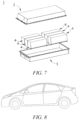
- the battery pack 1 may comprise a battery box and a plurality of battery modules 4 arranged in the battery box.
- the battery box comprises an upper box body 2 and a lower box body 3, wherein the upper box body 2 may cover the lower box body 3 to form a closed space for accommodating the battery modules 4.
- a plurality of the battery modules 4 may be arranged in the battery box in any manner.
- the present application further provides a power consuming device which comprises at least one of the secondary battery, the battery module, or the battery pack.
- the secondary battery, the battery module or the battery pack may be used as a power source of the device or as an energy storage unit of the device.
- the device may be, but is not limited to, a mobile device (e.g., a mobile phone, a laptop computer, etc.), an electric vehicle (e.g., a pure electric vehicle, a hybrid electric vehicle, a plug-in hybrid electric vehicle, an electric bicycle, an electric scooter, an electric golf cart, an electric truck, etc.), an electric train, ship, a satellite, an energy storage system, etc.
- a mobile device e.g., a mobile phone, a laptop computer, etc.
- an electric vehicle e.g., a pure electric vehicle, a hybrid electric vehicle, a plug-in hybrid electric vehicle, an electric bicycle, an electric scooter, an electric golf cart, an electric truck, etc.
- an electric train ship, a satellite, an
- the device may incorporate the secondary battery, the battery module or the battery pack according to its usage requirements.
- Fig. 8 shows a device as an example.
- the device is a pure electric vehicle, a hybrid electric vehicle, a plug-in hybrid electric vehicle or the like.
- a battery pack or a battery module may be used.
- the device may be a mobile phone, a tablet computer, a laptop computer, etc.
- the device is generally required to be thin and light, and may use a secondary battery as a power source.
- SiO 2 particles having a Dv50 particle size of 450 nm were blade-coated onto one surface of a 12 ⁇ m first base film by means of a scraper blade to a thickness of 3 ⁇ m, and then irradiated with an infrared heat source at a temperature of 160°C for 10 min.
- the second base film was irradiated with an infrared heat source at a temperature of 140°C for 8 min.
- SiO 2 particles having a Dv50 particle size of 450 nm were ultrasonically dispersed and prepared into a SiO2 particle aqueous dispersion with a concentration of 20wt%, then the dispersion was evenly coated onto one surface of a first base film, and then the film was dried in an oven at a temperature of 100°C for 30 min.
- the second base film was irradiated with an infrared heat source at a temperature of 140°C for 8 min.
- the SiO 2 particle coating was arranged between the two heated base films, and the base films were compounded by means of a thermal compounding roller at a temperature of 130°C, and at a pressure of the thermal compounding roller of 5 MPa and a speed of the thermal compounding roller of 0.3 m/min.
- a separator was obtained, and finally wound by means of a winding device and stored.
- Polyethylene, a mineral oil, and 4-methylphenol were uniformly mixed according to a weight ratio of 1 : 10 : 0.005.
- the mixture was heated to 130°C by means of a co-extrusion system, and continuously co-extruded at a rotating speed of 200 revolutions per minute by means of a twin-screw co-extrusion system, then treated by means of a casting and cooling roller at a temperature of 80°C so as to obtain a casted base film A and a casted base film B.
- SiO 2 ceramic inorganic particles having a Dv50 particle size of 450 nm were uniformly coated onto one surface of the casted base film A by means of a scraper blade until a coating thickness of 3 ⁇ m.
- the casted base film A, the ceramic inorganic particles, and the casted base film B were thermally compounded by means of a thermal compounding roller at a temperature of 120°C, a pressure of 4 MPa, and a speed of 1.5 m/min. Then the compound base film was stretched by means of a bidirectional asynchronous stretching system, the mineral oil in the stretched compound base film was extracted with a dichloromethane solution to form a porous structure so as to obtain a separator. The separator was wound by means of a winding device. Note: The casted base film A and the casted base film B form a first base film and a second base film, respectively.
- Examples 4-16 were basically the same as example 1, except that the parameters of the first base film, the second base film, the inorganic particle and/or the intermediate layer were different, specifically as shown in Table 1 below.
- SiO 2 particles having a Dv50 particle size of 450 nm and PVDF were dissolved in N-methylpyrrolidone according to a weight ratio of 0.985 : 0.015, and prepared into a ceramic solution having a solid content (the total amount of SiO 2 particles and PVDF) of 50 wt%.
- the ceramic solution was sprayed onto a surface of the first base film, and the second base film was attached to the first base film with the surface coated with the ceramic solution and rolled by means of a hot roller at a temperature of 130°C, a pressure of the hot roller of 0.5 MPa, and a speed of the hot roller of 0.3 m/min, so as to obtain a separator.
- the separators prepared in each example and comparative example all had a structure where a first porous base film, an intermediate layer, and a second porous base film were stacked.
- a thickness of the intermediate layer was determined by a thickness of the inorganic particle.
- a thickness of the first base film and the second base film was that of the corresponding first porous base film and second porous base film in the separator, respectively.
- a ⁇ 18 mm lithium sheet was used as a positive electrode and a negative electrode, and has a thickness of 500 ⁇ m.
- An interlayer was the separator prepared in each example and comparative example. The same amount of an electrolyte solution was dropwise added in a certain sequence.
- a 2430 type button battery was assembled and a model of the electrolyte solution was 1 mol/L LiPF 6 + EC/DMC (a volume ratio of EC to DMC was 1 : 1).
- the prepared button battery was subjected to an alternating current impedance test by means of Solartron at a frequency of 0.01-100,000 Hz, so as to obtain alternating current impedance data.
- Liquid phase ionic resistance data Rs was extracted from the data. Table 1 No.
- the Dv50 particle size of the inorganic particle was 200 nm to 2 ⁇ m, which is helpful to improve the bonding between the layers of the separators and the wettability with an electrolyte solution with respect to comparative example 1, thereby further improving the capacity performance of the battery.
- the inorganic particle has a Dv50 particle size of 300-800 nm.
- the separator may keep an alternating current impedance of the secondary battery at a relatively low level on the basis of obtaining a relatively good film layer bonding.
Landscapes
- Chemical & Material Sciences (AREA)
- Chemical Kinetics & Catalysis (AREA)
- Electrochemistry (AREA)
- General Chemical & Material Sciences (AREA)
- Engineering & Computer Science (AREA)
- Inorganic Chemistry (AREA)
- Composite Materials (AREA)
- Materials Engineering (AREA)
- Manufacturing & Machinery (AREA)
- Ceramic Engineering (AREA)
- Cell Separators (AREA)
Applications Claiming Priority (1)
| Application Number | Priority Date | Filing Date | Title |
|---|---|---|---|
| PCT/CN2022/094021 WO2023221072A1 (zh) | 2022-05-20 | 2022-05-20 | 隔离膜及其制备方法、含有其的二次电池及用电装置 |
Publications (2)
| Publication Number | Publication Date |
|---|---|
| EP4513652A1 true EP4513652A1 (de) | 2025-02-26 |
| EP4513652A4 EP4513652A4 (de) | 2025-09-03 |
Family
ID=88834334
Family Applications (1)
| Application Number | Title | Priority Date | Filing Date |
|---|---|---|---|
| EP22942112.8A Pending EP4513652A4 (de) | 2022-05-20 | 2022-05-20 | Separator und herstellungsverfahren dafür, sekundärbatterie mit dem separator und elektrische vorrichtung |
Country Status (3)
| Country | Link |
|---|---|
| US (1) | US20240304946A1 (de) |
| EP (1) | EP4513652A4 (de) |
| WO (1) | WO2023221072A1 (de) |
Families Citing this family (1)
| Publication number | Priority date | Publication date | Assignee | Title |
|---|---|---|---|---|
| CN120097354B (zh) * | 2025-02-21 | 2025-09-16 | 广东工业大学 | 一种二氧化硅-四氧化三铁磁性颗粒及其制备方法和应用 |
Family Cites Families (10)
| Publication number | Priority date | Publication date | Assignee | Title |
|---|---|---|---|---|
| US6080507A (en) * | 1998-04-13 | 2000-06-27 | Celgard Inc. | Trilayer battery separator |
| DE102012004161A1 (de) * | 2012-03-05 | 2013-09-05 | Treofan Germany Gmbh & Co. Kg | Hochporöse Separator-Folie mit partieller Beschichtung |
| CN103545472B (zh) * | 2012-07-17 | 2016-03-02 | 比亚迪股份有限公司 | 一种锂电池用复合隔膜及其制备方法和包括该复合隔膜的锂电池 |
| CN105374969A (zh) * | 2015-10-28 | 2016-03-02 | 惠州市吉美泰电子科技有限公司 | 一种带夹层锂电池隔膜、锂电池及锂电池隔膜制造方法 |
| CN108189499B (zh) * | 2017-12-14 | 2020-11-24 | 深圳市星源材质科技股份有限公司 | 一种多层复合膜及其制备方法 |
| CN109994691B (zh) * | 2017-12-29 | 2021-09-21 | 宁德时代新能源科技股份有限公司 | 一种隔离膜,其制备方法及包括该隔离膜的电化学装置 |
| JP7166773B2 (ja) * | 2018-03-30 | 2022-11-08 | 旭化成株式会社 | 蓄電デバイス用セパレータ及びそれを用いた積層体、捲回体、リチウムイオン二次電池、並びに蓄電デバイス |
| CN109148795A (zh) * | 2018-09-08 | 2019-01-04 | 佛山皖和新能源科技有限公司 | 一种电池复合隔膜的制备方法 |
| KR102787019B1 (ko) * | 2018-12-13 | 2025-03-27 | 현대자동차주식회사 | 리튬 이차전지 및 그 제조방법 |
| JP7021403B1 (ja) * | 2020-04-13 | 2022-02-16 | 旭化成株式会社 | 複合型積層化学架橋セパレータ |
-
2022
- 2022-05-20 WO PCT/CN2022/094021 patent/WO2023221072A1/zh not_active Ceased
- 2022-05-20 EP EP22942112.8A patent/EP4513652A4/de active Pending
-
2024
- 2024-05-15 US US18/664,286 patent/US20240304946A1/en active Pending
Also Published As
| Publication number | Publication date |
|---|---|
| EP4513652A4 (de) | 2025-09-03 |
| US20240304946A1 (en) | 2024-09-12 |
| WO2023221072A1 (zh) | 2023-11-23 |
Similar Documents
| Publication | Publication Date | Title |
|---|---|---|
| CN113875051B (zh) | 二次电池、其制备方法及含有该二次电池的装置 | |
| CN115885396B (zh) | 正极活性材料、锂离子二次电池、电池模块、电池包和用电装置 | |
| US12300851B2 (en) | Separator, preparation method therefor and related secondary battery, battery module, battery pack and device | |
| US12300850B2 (en) | Separator, secondary battery comprising same and related battery module, battery pack and device | |
| CN113875047B (zh) | 二次电池及其制备方法、含有该二次电池的装置 | |
| EP4510357A1 (de) | Separator und herstellungsverfahren dafür, sekundärbatterie und elektrische vorrichtung | |
| US12512559B2 (en) | Separator, preparation method therefor and related secondary battery, battery module, battery pack and device | |
| EP4099495A1 (de) | Separator, herstellungsverfahren dafür und sekundärbatterie, batteriemodul, batteriepack und damit verbundene vorrichtung | |
| US20230016626A1 (en) | Separator, preparation method therefor and related secondary battery, battery module, battery pack and device | |
| US12132226B2 (en) | Separator, secondary battery containing such separator, and related battery module, battery pack, and apparatus | |
| EP4184701A1 (de) | Elektrodenplatte und sekundärbatterie damit | |
| US20240304946A1 (en) | Separator, preparation method therefor, secondary battery containing same, and power consuming device | |
| EP4597724A1 (de) | Separator und herstellungsverfahren dafür, sekundärbatterie und elektrische vorrichtung | |
| CN119029492A (zh) | 隔离膜及其制备方法、二次电池及其制备方法和用电装置 | |
| EP4071864B1 (de) | Polymer-stromabnehmer, herstellungsverfahren dafür, und sekundärbatterie, batteriemodul, batteriepack und zugehörige vorrichtung | |
| US20240421289A1 (en) | Negative electrode active material and preparation method thereof, secondary battery, and electric apparatus | |
| CN113966558B (zh) | 一种二次电池、其制备方法及含有该二次电池的装置 | |
| EP3358652A1 (de) | Positivelektrode für lithium-ionen-sekundärbatterie sowie lithium-ionen-sekundärbatterie | |
| EP4597726A1 (de) | Separator, herstellungsverfahren dafür, sekundärbatterie und elektrische vorrichtung | |
| EP4611155A1 (de) | Separator, sekundärbatterie und elektrische vorrichtung | |
| EP4621972A1 (de) | Separator, sekundärbatterie und elektrische vorrichtung | |
| CN118020163B (zh) | 负极极片、二次电池、电池模组、电池包及用电装置 | |
| EP4451449A1 (de) | Separator und herstellungsverfahren dafür, sekundärbatterie und elektrische vorrichtung | |
| EP4601104A1 (de) | Separator, sekundärbatterie und elektrische vorrichtung | |
| CN119343822A (zh) | 隔离膜、二次电池和用电装置 |
Legal Events
| Date | Code | Title | Description |
|---|---|---|---|
| STAA | Information on the status of an ep patent application or granted ep patent |
Free format text: STATUS: THE INTERNATIONAL PUBLICATION HAS BEEN MADE |
|
| PUAI | Public reference made under article 153(3) epc to a published international application that has entered the european phase |
Free format text: ORIGINAL CODE: 0009012 |
|
| STAA | Information on the status of an ep patent application or granted ep patent |
Free format text: STATUS: REQUEST FOR EXAMINATION WAS MADE |
|
| 17P | Request for examination filed |
Effective date: 20241122 |
|
| AK | Designated contracting states |
Kind code of ref document: A1 Designated state(s): AL AT BE BG CH CY CZ DE DK EE ES FI FR GB GR HR HU IE IS IT LI LT LU LV MC MK MT NL NO PL PT RO RS SE SI SK SM TR |
|
| REG | Reference to a national code |
Ref country code: DE Ref legal event code: R079 Free format text: PREVIOUS MAIN CLASS: H01M0050409000 Ipc: H01M0050403000 |
|
| DAV | Request for validation of the european patent (deleted) | ||
| DAX | Request for extension of the european patent (deleted) | ||
| A4 | Supplementary search report drawn up and despatched |
Effective date: 20250806 |
|
| RIC1 | Information provided on ipc code assigned before grant |
Ipc: H01M 50/403 20210101AFI20250731BHEP Ipc: H01M 50/409 20210101ALI20250731BHEP Ipc: H01M 50/417 20210101ALI20250731BHEP Ipc: H01M 50/434 20210101ALI20250731BHEP Ipc: H01M 50/446 20210101ALI20250731BHEP Ipc: H01M 50/451 20210101ALI20250731BHEP Ipc: H01M 50/457 20210101ALI20250731BHEP Ipc: H01M 50/489 20210101ALI20250731BHEP |