EP4513084A1 - Brenneranordnung und kocher - Google Patents
Brenneranordnung und kocher Download PDFInfo
- Publication number
- EP4513084A1 EP4513084A1 EP24195685.3A EP24195685A EP4513084A1 EP 4513084 A1 EP4513084 A1 EP 4513084A1 EP 24195685 A EP24195685 A EP 24195685A EP 4513084 A1 EP4513084 A1 EP 4513084A1
- Authority
- EP
- European Patent Office
- Prior art keywords
- burner
- flame
- flame holes
- height difference
- holes
- Prior art date
- Legal status (The legal status is an assumption and is not a legal conclusion. Google has not performed a legal analysis and makes no representation as to the accuracy of the status listed.)
- Granted
Links
Images







Classifications
-
- F—MECHANICAL ENGINEERING; LIGHTING; HEATING; WEAPONS; BLASTING
- F23—COMBUSTION APPARATUS; COMBUSTION PROCESSES
- F23D—BURNERS
- F23D14/00—Burners for combustion of a gas, e.g. of a gas stored under pressure as a liquid
- F23D14/02—Premix gas burners, i.e. in which gaseous fuel is mixed with combustion air upstream of the combustion zone
- F23D14/04—Premix gas burners, i.e. in which gaseous fuel is mixed with combustion air upstream of the combustion zone induction type, e.g. Bunsen burner
- F23D14/06—Premix gas burners, i.e. in which gaseous fuel is mixed with combustion air upstream of the combustion zone induction type, e.g. Bunsen burner with radial outlets at the burner head
-
- F—MECHANICAL ENGINEERING; LIGHTING; HEATING; WEAPONS; BLASTING
- F23—COMBUSTION APPARATUS; COMBUSTION PROCESSES
- F23D—BURNERS
- F23D2207/00—Ignition devices associated with burner
-
- F—MECHANICAL ENGINEERING; LIGHTING; HEATING; WEAPONS; BLASTING
- F23—COMBUSTION APPARATUS; COMBUSTION PROCESSES
- F23D—BURNERS
- F23D2900/00—Special features of, or arrangements for burners using fluid fuels or solid fuels suspended in a carrier gas
- F23D2900/14—Special features of gas burners
- F23D2900/14062—Special features of gas burners for cooking ranges having multiple flame rings
Definitions
- the invention relates to the technical field of kitchen appliances, and in particular, to a burner assembly and a cooker.
- a burner assembly and a cooker.
- an embodiment of the invention provides a burner assembly.
- the burner assembly includes a first burner of a ring shape and a second burner of a ring shape.
- the first burner has first flame holes formed on an inner circumferential edge of the first burner.
- the second burner has second flame holes formed on an inner circumferential edge of the second burner.
- the second burner is disposed above the first burner and has an inner diameter greater than an inner diameter of the first burner.
- the second burner is disposed above the first burner. Moreover, the inner diameter of the second burner is greater than the inner diameter of the first burner. Therefore, when ignition of the first burner is successful, the second burner can be ignited from an inner circumference of the second burner in a manner of flame upward spread, to ensure flame uniformity of a pot bottom.
- This design is simple in structure, and convenient and quick.
- the inner diameter of the second burner is 1.2 times to 2.5 times the inner diameter of the first burner.
- the inner diameter of the second burner is 1.5 times the inner diameter of the first burner.
- the first burner includes: a first lower plate having first lower hole channels; a first upper plate disposed above the first lower plate; and a first partition disposed between the first lower plate and the first upper plate and separating the first lower hole channels from the first upper hole channels.
- the first upper plate has first upper hole channels corresponding to the first lower hole channels. The first flame holes are formed by the first lower hole channels and the first upper hole channels.
- An angle ⁇ 1 of a plane where the first upper plate is located relative to a depth direction of each first flame hole is greater than 0° and smaller than 90°.
- each first flame hole of the first burner is inclined inwardly into a conical shape. Therefore, a flame gathering effect of the first burner is ensured. Further, a flame intensity and heating efficiency of the first burner are increased.
- the angle ⁇ 1 is greater than 0° and smaller than 60°.
- the angle ⁇ 1 is 40°.
- the intensity of the flames generated by the first burner is ensured to be improved, providing a better heating effect of a bottom of a cooking appliance.
- the second burner includes: a second lower plate having second lower hole channels; a second upper plate disposed above the second lower plate; and a second partition disposed between the second lower plate and the second upper plate and separating the second lower hole channels from the second upper hole channels.
- the second upper plate has second upper hole channels corresponding to the second lower hole channels, and the second flame holes are formed by the second lower hole channels and the second upper hole channels.
- An angle ⁇ 2 of a plane where the second upper plate is located relative to a depth direction of each second flame hole is greater than 0° and smaller than 90°.
- each second flame hole of the second burner is inclined inwardly into a conical shape. Therefore, a flame gathering effect of the second burner is ensured. Further, a flame intensity and heating efficiency of the second burner are improved.
- the angle ⁇ 2 is greater than 0° and smaller than 60°.
- the angle ⁇ 2 is 40°.
- the intensity of the flames generated by the second burner is ensured to be improved, providing the better heating effect of the bottom of the cooking appliance.
- a first height difference exists between the first flame holes and the second flame holes.
- the first height difference is greater than 15 mm and smaller than 40 mm.
- the first height difference is greater than 40 mm, the first height difference is too large, and accordingly a distance between the first burner and the second burner is too large, making it difficult to assist the ignition of the second burner by the flames from the first burner.
- the first height difference is smaller than 15 mm, the first height difference is too small, and accordingly the distance between the first burner and the second burner is too small, resulting in a poor heat dissipation effect. Therefore, internal heat of the burner assembly is too high, easily causing safety hazards.
- a first height difference exists between the first flame holes and the second flame holes.
- the first height difference is greater than 20 mm and smaller than 30 mm.
- the ignition efficiency and the heat dissipation efficiency of the burner assembly are further improved.
- the first height difference is greater than 30 mm, the first height difference is too large, so that the distance between the first burner and the second burner is too large, making it difficult to assist the ignition of the second burner by the flames from the first burner.
- the first height difference is smaller than 20 mm, the first height difference is too small, and accordingly the distance between the first burner and the second burner is too small, resulting in the poor heat dissipation effect. Therefore, the internal heat of the burner assembly is too high, easily causing the safety hazards.
- a first height difference exists between the first flame holes and the second flame holes.
- the first height difference is 23.65 mm.
- a depth direction of each first flame hole is inclined relative to a radial direction of the first burner to define a first deflection angle.
- the first deflection angle is greater than 0° and smaller than 45°.
- the flames at the first flame holes spirally gather, to improve the flame intensity, ensuring burning efficiency of a gas.
- a depth direction of each first flame hole is inclined relative to a radial direction of the first burner to form a first deflection angle.
- the first deflection angle is greater than 0° and smaller than 30°.
- a depth direction of each first flame hole is inclined relative to a radial direction of the first burner to form a first deflection angle.
- the first deflection angle is 30°.
- a depth direction of each second flame hole is inclined relative to a radial direction of the second burner to define a second deflection angle.
- the second deflection angle is greater than 0° and smaller than 45°.
- the flames at the second flame holes spirally gather, to improve the flame intensity, ensuring the burning efficiency of the gas.
- a depth direction of each second flame hole is inclined relative to a radial direction of the second burner to define a second deflection angle.
- the second deflection angle is greater than 0° and smaller than 30°.
- a depth direction of each second flame hole is inclined relative to a radial direction of the second burner to define a second deflection angle.
- the second deflection angle is 30°.
- the flame intensity is high and the heating efficiency is significant while ensuring the flame gathering of the second flame holes.
- the first burner or the second burner is kept at a suitable distance from the deflector, to improve air flowability inside the burner assembly, improving the burning efficiency of the burner assembly.
- the second height difference is greater than 0 mm and smaller than 8 mm.
- a top of the first burner is kept at a suitable distance from the deflector to improve secondary air supply, improving the burning efficiency of the first burner.
- the second height difference is 5 mm.
- the third height difference is greater than 0 mm and smaller than 15 mm.
- a bottom of the second burner is kept at an appropriate distance from the deflector to improve the secondary air supply, improving the burning efficiency and ensuring the flame uniformity of the burner assembly.
- the third height difference is 9 mm.
- the secondary air supply amount is sufficient, and thus the burning efficiency of the burner assembly is significant and the flame uniformity is good.
- the first lower plate is depressed downwardly to form the first lower hole channels
- the first upper plate is arched upwardly to form the first upper hole channels.
- the first lower hole channels and the first upper hole channels directly face towards each other to form the first flame holes of the first burner.
- the first upper hole channels of the first upper plate directly face towards the first lower hole channels of the first lower plate to allow the first flame holes of the first burner to be formed in such a manner that the first flame holes directly face towards each other. In this way, a total area of the flame holes of the first burner is increased. Further, a flame intensity and an upper load limit of the first burner are increased.
- the second lower plate is depressed downwardly to form the second lower hole channels
- the second upper plate is arched upwardly to form the second upper hole channels.
- the second lower hole channels and the second upper hole channels directly face towards each other to form the second flame holes of the second burner.
- the second upper hole channels of the second upper plate directly face towards the second lower hole channels of the second lower plate to allow the second flame holes of the second burner to be formed in such a manner that the second flame holes directly face towards each other.
- a total area of the flame holes of the second burner is increased. Further, a flame intensity and an upper load limit of the second burner are increased.
- first flame transfer gaps are formed between the first upper plate and the first partition. Two adjacent first flame holes are in communication with each other via the corresponding first flame transfer gap.
- second flame transfer gaps are formed between the second upper plate and the second partition. Two adjacent second flame holes are in communication with each other via the corresponding second flame transfer gap.
- the burner assembly further includes an ignition device.
- the ignition device includes an ignition needle, a thermocouple, and a first support. The ignition needle and the thermocouple are fixed to the first support. The ignition needle of the ignition device is arranged adjacent to the first flame holes.
- the ignition needle and the thermocouple are integrated into one piece in the ignition device.
- the ignition needle can be positioned adjacent to the first flame holes and located inside the burner assembly, to improve ignition success rates of the first burner and the second burner and simplify mounting.
- each of the first burner and the second burner includes a burner body and a deflector.
- the burner body has a gas channel formed in the burner body.
- the burner body has inner ring flame holes in communication with the gas channel and outer ring flame holes communication with the gas channel.
- the outer ring flame holes are arranged around the inner ring flame holes.
- the burner body further has an air supplement channel independent of the gas channel.
- the air supplement channel includes an air inlet located at an outer side wall of the burner body and an air outlet located between the inner ring flame holes and the outer ring flame holes.
- the deflector is disposed at the air outlet.
- the deflector is engaged with an inner wall of the air supplement channel to define an inner-ring air supplement opening for supplementing air to flow towards the inner ring flame holes and an outer-ring air supplement opening for supplementing air to flow towards the outer ring flame holes.
- the cooker includes the burner assembly according to any one of the above embodiments.
- the second burner is disposed above the first burner. Moreover, the inner diameter of the second burner is greater than the inner diameter of the first burner. Therefore, when the first burner is successfully ignited, the second burner can be ignited from the inner circumference of the second burner in a manner of flame upward spread, to ensure the flame uniformity at the pot bottom.
- This design is simple in structure, and convenient and quick.
- an embodiment of the invention provides a burner assembly.
- the burner assembly includes a first burner of a ring shape, a second burner of a ring shape, and an ignition device.
- the first burner has first flame holes formed on an inner circumferential edge of the first burner.
- the second burner has second flame holes formed on an inner circumferential edge of the second burner.
- the second burner is disposed above the first burner and has an inner diameter greater than an inner diameter of the first burner.
- the ignition device includes an ignition needle, a thermocouple, and a first support. The ignition needle and the thermocouple are fixed to the first support.
- the ignition needle of the ignition device is arranged adjacent to the first flame holes.
- the ignition needle and the thermocouple are integrated into one piece in the ignition device.
- the ignition needle can be positioned adjacent to the first flame holes and located inside the burner assembly, to improve the ignition success rates of the first burner and the second burner and simplify the mounting.
- the ignition device is disposed between the first burner and the second burner.
- the ignition device is disposed inside the burner assembly to avoid damage due to accidental collisions, improving stability and ignition efficiency of the ignition device.
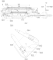
- an angle ⁇ of a length direction of the ignition needle relative to a central axis of the first burner is greater than 30° and smaller than 90°.
- the ignition needle is disposed adjacent to the first flame holes from above the inner circumferential edge of the first burner to ignite a gas at the first flame holes. Therefore, the ignition success rate is improved.
- the angle ⁇ of a length direction of the ignition needle relative to a central axis of the first burner is greater than 60° and smaller than 70°.
- the ignition device is disposed at an inner side of the first burner.
- the ignition needle is located adjacent to the first flame holes from a position below the inner circumferential edge of the first burner to ignite the gas at the first flame holes. Therefore, the ignition success rate is improved.
- the first support includes a fixing sheet and two groups of elastic sheets extending from the fixing sheet.
- An engagement groove is formed by each group of elastic sheets. The ignition needle and the thermocouple are fixed in the engagement groove, respectively.
- the first burner includes: a first lower plate having first lower hole channels; a first upper plate disposed above the first lower plate; and a first partition disposed between the first lower plate and the first upper plate and separating the first lower hole channels from the first upper hole channels.
- the first upper plate has first upper hole channels corresponding to the first lower hole channels. The first lower hole channels and the first upper hole channels directly face towards each other to form the first flame holes.
- the first upper hole channels of the first upper plate directly faces towards the first lower hole channels of the first lower plate to allow the first flame holes of the first burner to be formed in such a manner that the first flame holes directly face towards each other.
- the total area of the flame holes of the first burner is increased. Further, the flame intensity and the upper load limit of the first burner are increased.
- the first partition is provided with a protrusion.
- the protrusion is configured to be in contact with an electric arc generated by an ignition needle.
- the protrusion is formed on the first partition and is configured to be in contact with the electric arc generated by the ignition needle to prevent the electric arc from uncontrollably moving. Therefore, an ignition success rate is increased and the user experience is enhanced.
- the second burner includes: a second lower plate having second lower hole channels; a second upper plate disposed above the second lower plate; and a second partition disposed between the second lower plate and the second upper plate and separating the second lower hole channels from the second upper hole channels.
- the second upper plate has second upper hole channels corresponding to the second lower hole channels, and the second lower hole channels and the second upper hole channels directly face towards each other to form the second flame holes.
- the second upper hole channels of the second upper plate directly faces towards the second lower hole channels of the second lower plate to allow the second flame holes of the second burner to be formed in such a manner that the second flame holes directly face towards each other.
- the total area of the flame holes of the second burner is increased. Further, the flame intensity and the upper load limit of the second burner are increased.
- the inner diameter of the second burner is 1.2 times to 2.5 times the inner diameter of the first burner.
- the inner diameter of the second burner is 1.5 times the inner diameter of the first burner.
- the heated area of the pot bottom is increased and the cooking efficiency are further improved when it is ensured that the flames better cover the pot bottom by adjusting the appropriate flame position.
- the burner assembly includes a second support.
- the first support has a fixing hole.
- the ignition device is mounted on the second support through the fixing hole.
- the ignition needle can face towards the protrusion and be located adjacent to the protrusion, ensuring the ignition efficiency.
- a first height difference exists between the first flame holes and the second flame holes.
- the first height difference is greater than 15 mm and smaller than 40 mm.
- the ignition efficiency and the heat dissipation efficiency of the burner assembly are improved.
- the first height difference is greater than 40 mm, the first height difference is too large, and accordingly the distance between the first burner and the second burner is too large, making it difficult to assist the ignition of the second burner by the flames from the first burner.
- the first height difference is smaller than 15 mm, the first height difference is too small, and accordingly the distance between the first burner and the second burner is too small, resulting in the poor heat dissipation effect. Therefore, the internal heat of the burner assembly is too high, easily causing the safety hazards.
- a first height difference exists between the first flame holes and the second flame holes.
- the first height difference is greater than 20 mm and smaller than 30 mm.
- the ignition efficiency and the heat dissipation efficiency of the burner assembly are further improved.
- the first height difference is greater than 30 mm, the first height difference is too large, and accordingly the distance between the first burner and the second burner is too large, making it difficult to assist the ignition of the second burner by the flames from the first burner.
- the first height difference is smaller than 20 mm, the first height difference is too small, and accordingly the distance between the first burner and the second burner is too small, resulting in the poor heat dissipation effect. Therefore, the internal heat of the burner assembly is too high, easily causing the safety hazards.
- a first height difference exists between the first flame holes and the second flame holes.
- the first height difference is 23.65 mm.
- the burner assembly includes a deflector disposed between the first burner and the second burner.
- a second height difference exists between the deflector and a top of each first flame hole.
- a third height difference exists between the deflector and a bottom of each second flame hole. The third height difference is greater than the second height difference.
- the first burner or the second burner is kept at a suitable distance from the deflector, to improve the air flowability inside the burner assembly, improving the burning efficiency of the burner assembly.
- the second height difference is greater than 0 mm and smaller than 8 mm.
- the top of the first burner is kept at a suitable distance from the deflector to improve the secondary air supply, improving the burning efficiency of the first burner.
- the second height difference is 5 mm.
- the secondary air supply amount is sufficient, and thus the burning efficiency of the first burner is high.
- the third height difference is greater than 0 mm and smaller than 15 mm.
- the bottom of the second burner is kept at an appropriate distance from the deflector to improve the secondary air supply, improving the burning efficiency and ensuring the flame uniformity of the burner assembly.
- the third height difference is 9 mm.
- the secondary air supply amount is sufficient, and thus the burning efficiency of the burner assembly is high and the flame uniformity is good.
- first flame transfer gaps are formed between the first upper plate and the first partition. Two adjacent first flame holes are in communication with each other via the corresponding first flame transfer gap.
- the two adjacent independent first flame holes are communicated with each other, ensuring the integrated formation of flames, further improving the flame transfer capability and the resistance to the separation of the flames from the flame holes of the first burner.
- second flame transfer gaps are formed between the second upper plate and the second partition. Two adjacent second flame holes are in communication with each other via the corresponding second flame transfer gap.
- the two adjacent independent second flame holes are communicated with each other, ensuring the integrated formation of flames, further improving the flame transfer capability and the resistance to the separation of the flames from the flame holes of the second burner.
- the cooker includes the burner assembly according to any one of the above embodiments.
- the ignition needle and the thermocouple are integrated into one piece in the ignition device.
- the ignition needle can be positioned adjacent to the first flame holes and located inside the burner assembly, to improve the ignition success rates of the first burner and the second burner and simplify the mounting.
- an embodiment of the invention provides a burner.
- the burner includes a burner body and a deflector.
- the burner body has a gas channel formed in the burner body.
- the burner body has inner ring flame holes in communication with the gas channel and outer ring flame holes in communication with the gas channel.
- the outer ring flame holes are arranged around the inner ring flame holes.
- the burner body further has an air supplement channel independent of the gas channel.
- the air supplement channel includes an air inlet located at an outer side wall of the burner body and an air outlet located between the inner ring flame holes and the outer ring flame holes.
- the deflector is disposed at the air outlet. The deflector is engaged with an inner wall of the air supplement channel to define an inner-ring air supplement opening for supplementing air to flow towards the inner ring flame holes and an outer-ring air supplement opening for supplementing air to flow towards the outer ring flame holes.
- the burner further includes a mounting support having two connection portions and a first fixing portion.
- the deflector is connected to the first fixing portion.
- the burner body includes two separate burner units. One of the two burner units is connected to a connection portion. Moreover, one of the two burner units has inner ring flame holes, and another one of the two burner units has outer ring flame holes.
- the gas channel is formed in an interior of each of the burner units. Moreover, a gap between the two burner units is formed as the air supply channel.
- the mounting support includes a base and at least two connection support feet connected to the base.
- Each of the connection support feet extends in a height direction of the burner and has two connection portions and a first fixing portion.
- the two burner units are spaced apart from each other in an extending direction of each connection support foot.
- the air supplement channel is formed by a gap between the two burner units in the height direction of the burner.
- a flow guide ring includes a flow guide body and a first connection foot connected to an outer edge of the flow guide body.
- the flow guide body is disposed at the air outlet, and the first connection foot is connected to the first fixing portion.
- the flow guide body has an outer edge and an inner edge.
- the outer edge is engaged with the inner wall of the air supplement channel to define the outer-ring air supplement opening.
- the inner edge is engaged with the inner wall of the air supplement channel to define the inner-ring air supplement opening.
- the flow guide body is obliquely disposed downwardly in a direction from the outer edge to the inner edge.
- the first connection foot is engaged with a surface of the connection portion to press and fix the burner unit having the inner ring flame holes.
- the flow guide body in the height direction of the burner, is located above the inner ring flame holes. Moreover, a projection of the inner ring flame holes on a horizontal plane is located within a projection of the flow guide body on the same horizontal plane.
- the deflector has an outer edge and an inner edge.
- a spacing between an upper surface of a part of the burner unit on which the inner ring flame holes are formed and the inner edge is greater than 0 mm and smaller than or equal to 8 mm; and/or in the height direction of the burner, a spacing between a lower surface of a part of the burner unit on which the outer ring flame holes are formed and the outer edge is greater than 0 mm and smaller than or equal to 15 mm; and/or in a radial direction of the burner unit, a spacing between an end surface of each inner ring flame hole and the inner edge is greater than or equal to 0 mm and smaller than or equal to 5 mm; and/or in the radial direction of the burner unit, a spacing between an end surface of each outer ring flame hole and the outer edge is greater than or equal to 10 mm and smaller than or equal to 30 mm.
- the burner assembly further includes an oil cup.
- the oil cup is fixed to the mounting support and located at an inner side of the inner ring flame holes.
- the oil cup has an accommodation cavity for accommodating dirt.
- the mounting support includes a base.
- the oil cup includes a cup body and a handle portion, the cup body is fixed to the base, the handle portion is connected to the cup body and extends away from the base, an accommodation cavity is formed by an outer circumferential surface of the handle portion and an inner side wall of the cup body; and/or the mounting support includes a base, a support outer edge is formed at an outer edge of the oil cup and hung on an engagement edge of the base.
- the support outer edge has a first guide surface at a side of the support outer edge adjacent to the base.
- the engagement edge of the base has a second guide surface in a guide engagement with the first guide surface.
- the burner assembly further includes a thermocouple and an igniter that are fixed to the mounting support.
- the deflector has an avoidance hole through which the thermocouple and the igniter pass.
- the burner assembly further includes a fixing support.
- the thermocouple and the igniter are mounted to the fixing support.
- the mounting support includes a base, at least two connection support feet, and a connection rib.
- the at least two connection support feet are connected to the base.
- the connection rib is connected to the base and/or the connection support feet.
- Each connection support foot extends in the height direction of the burner and has two connection portions and a first fixing portion.
- the connection rib has a second fixing portion.
- the fixing support is connected to the second fixing portion.
- connection rib further has a positioning protrusion
- the fixing support has a positioning hole into which the positioning protrusion is engaged in a positioning manner
- the fixing support includes a support body and two clamping elastic sheets.
- the support body is connected to the second fixing portion.
- the two clamping elastic sheets are connected to the support body.
- One of the clamping elastic sheets is used for clamping or releasing the thermocouple, and the other one of the clamping elastic sheets is used for clamping or releasing the igniter; and/or the connection rib is connected between the two connection support feet.
- the mounting support includes a base and at least two connection support feet connected to the base.
- Each connection support foot extends in the height direction of the burner and has two connection portions, a first fixing portion, and a third fixing portion.
- the two burner units are spaced apart from each other in the extending direction of each connection support foot.
- the burner further includes a pressing cover.
- the pressing cover includes a cover body and at least two second connection feet connected to an outer edge of the cover body. One of the second connection feet is connected to the third fixing portion, and the other one of the second connection feet is connected to the connection portion to clamp and fix the two burner units by cooperating with the connection support feet.
- the mounting support includes a base and at least two connection support feet connected to the base.
- Each of the connection support feet has two connection portions and a first fixing portion.
- the burner unit includes an ejection pipe portion and a stove portion fixedly connected to the ejection pipe portion.
- a gas channel is defined by an interior of the ejection pipe portion and an interior of the stove portion.
- the stove portion has inner ring flame holes or outer ring flame holes formed on the stove portion.
- the ejection pipe portion is connected to one of the connection support feet by the connection portion.
- the stove portion is connected to the rest of the connection support feet by the connection portion.
- the ejection pipe portion includes an ejection pipe and a mounting side.
- An ejection channel is formed by the ejection pipe and is in communication with the inner ring flame holes or the outer ring flame holes.
- the mounting side is connected to an outer edge of the ejection pipe.
- connection portion includes a first connection portion disposed on a connection support foot corresponding to the ejection pipe portion, and the mounting side is fixedly connected to the first connection portion.
- the first connection portion has a first connection hole formed on the connection support foot.
- the mounting side has a second connection hole formed on the mounting side. The mounting side and the connection support foot are fixedly connected by engaging a fastener into the first connection hole and the second connection hole.
- the stove portion includes a burning ring and a skirt.
- the burning ring internally has a burning channel in communication with the inner ring flame holes or the outer ring flame holes.
- the skirt is arranged around an outer edge of the burning ring.
- connection portion includes a second connection portion disposed on a connection support connected to the stove portion.
- the skirt is connected to the second connection portion.
- the second connection portion is an engagement groove formed on the connection support foot.
- the skirt is engaged into the engagement groove, allowing the skirt to be fixedly connected the connection support foot.
- each of the burner units includes an upper housing and a lower housing.
- the upper housing is connected to the lower housing in a covering manner.
- the ejection pipe portion is defined by a part of the upper housing and a part of the lower housing.
- the stove portion is defined by the rest part of the upper housing and the rest part of the lower housing.
- each of the upper housing and the lower housing is made of stainless steel.
- the burner unit on which the inner ring flame holes are formed further includes a first partition, a gap is formed between a part, on which the inner ring flame holes are formed, of the upper housing and a part, on which the inner ring flame holes are formed, of the lower housing, and the first partition is disposed in the gap and separates each inner ring flame holes into two sub-inner ring flame holes directly facing towards each other in the height direction of the burner; and/or the burner unit on which the outer ring flame holes are formed further includes a second partition, a gap is formed between a part, on which the outer ring flame holes are formed, of the upper housing and a part, on which forming the outer ring flame holes are formed, of the lower housing. The second partition is disposed in the gap and separates each outer ring flame holes into two sub-outer ring flame holes directly facing towards each other in the height direction of the burner.
- Embodiments of the invention provide a cooker.
- the cooker includes the burner as described above.
- the deflector is provided, and the inner-ring air supplement opening for air supplementing air to flow towards the inner ring flame holes and the outer-ring air supplement opening for supplementing air to flow towards the outer ring flame holes are defined through the engagement between the deflector and the inner wall of the air supplement channel at an air outlet of the air supplement channel formed by the burner body.
- the secondary air is branched into two sub-airflows through the guiding of the deflector.
- One of the sub-airflows flows towards the inner-ring air supplement opening and finally flows to the inner ring flame holes, and the other one of the sub-airflows flows towards the outer-ring air supplement opening and finally flows to the outer ring flame holes.
- the competition for air can be reduced between the flames generated at the inner ring flame holes and the flames generated at the outer ring flame holes. Therefore, the burning efficiency of the cooker and the burning efficiency of the burner 100 can be improved.
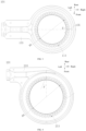
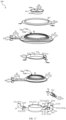
- a burner assembly 300 includes a first burner 101 and a second burner 201.
- the first burner 101 is of a ring shape and has first flame holes 113 formed on an inner circumferential edge of the first burner 101.
- the second burner 201 is of a ring shape and has second flame holes 213 formed on an inner circumferential edge of the second burner 201.
- the second burner 201 is disposed above the first burner 101 and has an inner diameter D2 greater than an inner diameter D1 of the first burner.
- the second burner 201 is disposed above the first burner 101. Moreover, the inner diameter D2 of the second burner is greater than the inner diameter D1 of the first burner. Therefore, when the first burner 101 is successfully ignited, the second burner 201 can be ignited from an inner circumference of the second burner 201 in a manner of flame upward spread, to ensure flame uniformity at a pot bottom. This design is simple in structure, and convenient and quick.
- the first burner 101 may be an inner ring burner for providing an inner ring flame to ensure a flame intensity and heating uniformity at a central part of the pot bottom.
- a plurality of first flame holes 113 are formed on the inner circumferential edge of the first burner 101, to ensure that the plurality of first flame holes 113 are arranged around the inner circumferential edge of the first burner 101 to be formed as an inner ring flame outlet to provide an annular inner flame. In this way, heating uniformity at the central part of the pot bottom is ensued.
- the second burner 201 may be an outer ring burner for providing an outer ring flame to ensure a flame intensity and heating uniformity at an edge of the pot bottom.
- a plurality of second flame holes 213 are formed on the inner circumferential edge of the second burner 201, to ensure that the plurality of second flame holes 213 are arranged around the inner circumferential edge of the second burner 201 to be formed as an outer ring flame outlet to provide an outer annular flame. In this way, the heating uniformity at the edge of the pot bottom is ensured.
- the inner diameter D1 of the first burner may be a diameter of the inner circumferential edge of the first burner 101, to provide an inner ring flame of a diameter of D1.
- the inner diameter D2 of the second burner may be a diameter of the inner circumferential edge of the second burner 201, to provide an outer ring flame of a diameter of D2.
- the inner diameter D2 of the second burner is greater than the inner diameter D1 of the first burner, to ensure that the first burner 101 provides the inner ring flame and the second burner 201 provides the outer ring flame in such a manner that the inner ring flame and the out ring flame cooperate with each other. In this way, it is ensured that the central part and the edge of the pot bottom are uniformly heated, allowing the entire pot bottom to be uniformly heated, further ensuring the flame uniformity at the pot bottom.
- the burner assembly 300 may be provided with an ignition needle (not shown) between the first burner 101 and the second burner 201 for providing an electric discharge arc, to ignite a gas at the first flame holes 113 to form an inner annular flame.
- a gas at the second flame holes 213 may be ignited by the inner annular flames generated at the first flame holes 113 from the inner circumferential edge of the second flame holes 213 in a manner of flame upward spread, to form an outer annular flame, ensuring the flame uniformity of the burner assembly 300, which is convenient and quick. Therefore, high ignition efficiency is provided.
- the first burner 101 may be stably disposed at an appropriate distance from the second burner 201, to ensure smooth air circulation at the first flame holes 113 inside the burner assembly 300, ensuring a normal operation of the first burner 101 and avoiding an insufficient intensity (or extinguishment) of the inner ring flame due to insufficient secondary air supplement. Therefore, the flame uniformity of the entire pot bottom is ensured.
- the first burner 101 or the second burner 201 may be used only, or the first burner 101 and the second burner 201 may be used together, which is not specifically limited herein.
- the inner diameter D2 of the second burner is 1.2 times to 2.5 times the inner diameter D1 of the first burner.
- the inner diameter of the first burner may be set as D1, to ensure that the annular flames generated by the first burner 101 can be better located in the central part of the pot bottom, and thus the flame intensity at the central part of the pot bottom is improved. Meanwhile, it is ensured that the central part of the pot bottom is heated uniformly.
- the inner diameter D2 of the second burner is 1.2 times to 2.5 times the inner diameter D1 of the first burner, to ensure that the flames generated by the burner assembly 300 can heat the pot bottom uniformly, improving a gas utilization rate and the cooking efficiency.
- the inner diameter D2 of the second burner may is greater than 1.2D1 and smaller than 2.5D1, which enables the flames generated by the second burner 201 to better cover the edge of the pot bottom. Therefore, it is ensured that the central part and the edge of the pot bottom are uniformly heated, improving the cooking efficiency.
- the inner diameter D2 of the second burner may satisfy 2.5D1 >D2> 1.2D1.
- the inner diameter D2 of the second burner may be 1.3D1, 1.5D1, 1.6D1, 1.9D1, 2.0D1, 2.3D1, 2.4D1, or other value that is greater than 1.2D1 and smaller than 2.5D1.
- the inner diameter D2 of the second burner is greater than 2.5D1
- the inner diameter D2 of the second burner is too large, which causes the outer ring flames generated at the second flame holes 213 to extend to a position outside the pot bottom, resulting in a too large distance between the outer ring flame and the inner ring flame at the pot bottom.
- heating amount is insufficient, and thus the flame uniformity of the burner assembly 300 is reduced.
- the outward extending of the gas causes a reduction in the gas utilization rate.
- a risk in which a user may be got burned due to a high temperature of a pot handle may occur.
- the inner diameter D2 of the second burner is smaller than 1.2D1
- the inner diameter D2 of the second burner is too small, which causes the outer ring flames generated at the second flame holes 213 to be adjacent to the inner ring flames generated at the first flame holes 113, resulting in excessive heating at the central part of the pot bottom and insufficient heating at the edge of the pot bottom. In this way, the entire pot bottom is heated unevenly, easily occurring safety risks.
- the inner diameter D2 of the second burner is 1.5 times the inner diameter D1 of the first burner.
- the inner diameter D2 of the second burner is 1.5 times the inner diameter D1 of the first burner, to allow the inner ring flames generated at the first flame holes 113 and the outer ring flames generated at the second flame holes 213 to be located at appropriate positions of the pot bottom. Therefore, heat supply and the flame uniformity at the pot bottom can be ensured better.
- the inner diameter D2 of the second burner may be D2 is equal to 1.5D1.
- the inner diameter D1 of the first burner is 80mm.
- the inner diameter D2 of the second burner is 120 mm, to ensure that the flames generated by the burner assembly 300 better cover the pot bottom, ensuring the flame uniformity and the flame intensity, to improve the cooking efficiency and the gas utilization rate.
- the inner diameter D1 of the first burner may be other values, as long as D2 is equal to 1.5D1, which is not specifically limited herein.
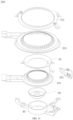
- the first burner 101 includes a first lower plate 122, a first upper plate 133 disposed above the first lower plate 122, and a first partition 143.
- the first lower plate 122 has first lower hole channels 125.
- the first upper plate 133 has first upper hole channels 135 corresponding to the first lower hole channels 125.
- the first flame holes 113 are formed by the first lower hole channels 125 and the first upper hole channels 135.
- the first partition 143 is disposed between the first lower plate 122 and the first upper plate 133 and separates the first lower hole channels 125 from the first upper hole channels 135.
- An angle ⁇ 1 of a plane where the first upper plate 133 is located relative to a depth direction of each first flame hole 113 is greater than 0° and smaller than 90°.
- each first flame hole 113 of the first burner 101 is inclined inwardly into a conical shape. Therefore, a flame gathering effect of the first burner 101 is ensured. Further, a flame intensity and heating efficiency of the first burner 101 are increased.
- the angle ⁇ 1 of the plane where the first upper plate 133 is located relative to the depth direction of each first flame hole 113 is greater than 0° and smaller than 90°, to allow each first flame hole 113 of the first burner 101 to be inclined inwardly into a conical shape. In this way, the flame gathering effect of the first burner 101 is ensured. Further, the flame intensity of the first burner 101 is improved to ensure a heating rate of a bottom of the cooking appliance.
- the angle ⁇ 1 is greater than 0° and smaller than 90°, i.e., 0 ° ⁇ ⁇ ⁇ 90 °. In some examples, the angle ⁇ 1 may be 5°, 10°, 30°, 45°, 60°, 75°, 85°, or other value that is greater than 0° and smaller than 90°.
- the first partition 143 is disposed between the first lower plate 122 and the first upper plate 133, and is employed to separate each first flame hole 113 formed by the first lower hole channels 125 and the first upper hole channels 135 into two sub-flame holes, and thus the sub-flame holes 41 located at upper and lower sides of the first partition 143 are independent of each other.
- each of the sub-flame holes has a reduced cross-sectional area and an increased depth.
- a path for the flames to flow back into a gas channel becomes relatively long.
- the flames reach the gas channel, it is insufficient to satisfy limiting conditions for deflagration. Therefore, a problem of flame-out noise of the first burner 101 can be effectively solved.
- the first partition 143 is disposed between the first lower hole channels 125 and the first upper hole channels 135, the first partition 143 may be made of a high-temperature and corrosion-resistant material.
- the first partition 143 may be a stainless-steel partition. In other embodiments, the first partition 143 may be an aluminum alloy partition, a copper alloy partition, or made of other materials, which is not specifically limited herein.
- the angle ⁇ 1 is greater than 0° and smaller than 60°.
- the angle ⁇ 1 of the plane where the first upper plate 133 is located relative to the depth direction of each first flame hole 113 is greater than 0° and smaller than 60°, in such a manner that each first flame hole 113 of the first burner 101 is inclined inwardly to be formed into the conical shape, ensuring that the flames generated at the first flame holes 113 of the first burner 101 better cover the bottom of the cooking appliance. Further, a heating rate of the first burner 101 is increased.
- the angle ⁇ 1 is greater than 0° and smaller than 60°, i.e. 0° ⁇ ⁇ ⁇ 60°. In some examples, the angle ⁇ 1 may be 5°, 10°, 15°, 25°, 30°, 45°, 50°, or other value that is greater than 0° and smaller than 60°.
- the angle ⁇ 1 is 40°.
- the intensity of the flames generated by the first burner 101 is ensured to be intense, providing a better heating effect for the bottom of the cooking appliance.
- the angle ⁇ 1 of the plane where the first upper plate 133 is located relative to the depth direction of each first flame hole 113 may be 40°.
- the flames are cohesive to cover and heat the bottom of the cooking appliance, ensuring a better heating effect for the bottom of the cooking appliance.
- the flames generated by the first burner 101 may better cover the bottom of the cooking appliance to ensure the heating effect for the bottom of the cooking appliance, increasing the gas utilization rate, which in turn increases the flame intensity and the heating rate of the first burner 101.
- the second burner 201 includes a second lower plate 222, a second upper plate 233 disposed above the second lower plate 222, and a second partition 243.
- the second lower plate 222 has second lower hole channels 225.
- the second upper plate 233 has second upper hole channels 235 corresponding to the second lower hole channels 225.
- the second flame holes 213 are formed by the second lower hole channels 225 and the second upper hole channels 235.
- the second partition 243 is disposed between the second lower plate 222 and the second upper plate 233 and separates the second lower hole channels 225 from the second upper hole channels 235.
- An angle ⁇ 2 of a plane where the second upper plate 233 is located relative to a depth direction of each second flame hole 213 is greater than 0° and smaller than 90°.
- each second flame hole 213 of the second burner 201 is inclined inwardly to be formed into a conical shape. In this way, a flame gathering effect of the second burner 201 is ensured. Further, a flame intensity and heating efficiency of the second burner 201 are increased.
- the angle ⁇ 2 of the plane where the second upper plate 233 is located relative to the depth direction of each second flame hole 213 is greater than 0° and smaller than 90°in such a manner that each second flame hole 213 of the second burner 201 is inclined inwardly to be formed into the conical shape, ensuring the flame gathering effect of the second burner 201. Further, the flame intensity of the second burner 201 is increased to ensure the heating rate for the bottom of the cooking appliance.
- the angle ⁇ 2 is greater than 0° and smaller than 90°, i.e. 0° ⁇ ⁇ 2 ⁇ 90°.
- the angle ⁇ 2 may be 5°, 10°, 30°, 45°, 60°, 75°, 85°, or other value that is greater than 0° and smaller than 90°.
- the second partition 243 is disposed between the second lower plate 222 and the second upper plate 233, and is configured to separate each second flame hole 113 formed by the second lower hole channels 225 and the second upper hole channels 235 into two sub-flame holes, and thus the sub-flame holes 41 located at upper and lower sides of the second partition 243 is independent of each other.
- each of the sub-flame holes 41 has a reduced cross-sectional area and an increased depth.
- a path for the flames to flow back into the gas channel becomes relatively long.
- the flames reach the gas channel, it is insufficient to satisfy limiting conditions for deflagration. Therefore, a problem of flame-out noise of the second burner 201 can be effectively solved.
- the second partition 243 may be made of a high-temperature and corrosion-resistant material.
- the second partition 243 may be a stainless-steel partition. In other embodiments, the second partition 243 may be an aluminum alloy partition, a copper alloy partition, or made of other materials, which is not specifically limited herein.
- the angle ⁇ 2 is greater than 0° and smaller than 60°.
- the angle ⁇ 2 of the plane where the second upper plate 233 is located relative to the depth direction of each second flame hole 213 is greater than 0° and smaller than 60°, in such a manner that each second flame hole 213 of the second burner 201 is inclined inwardly to be formed into the conical shape, ensuring that flames generated at the second flame holes 213 of the second burner 201 better cover the bottom of the cooking appliance. Further, a heating rate of the second burner 201 is increased.
- the angle ⁇ 2 is greater than 0° and smaller than 60°, i.e. 0° ⁇ ⁇ 2 ⁇ 60°.
- the angle ⁇ 2 may be 5°, 10°, 15°, 25°, 30°, 45°, 50°, or other value that is greater than 0° and smaller than 60°.
- the angle ⁇ 2 is 40°.
- the intensity of the flames generated by the second burner 201 is ensured to be intense, providing a better heating effect for the bottom of the cooking appliance.
- the angle ⁇ 2 of the plane where the second upper plate 233 is located relative to the depth direction of each second flame hole 213 may be 40°.
- the flames are cohesive to cover and heat the bottom of the cooking appliance, ensuring a better heating effect for the bottom of the cooking appliance.
- the flames generated by the second burner 201 may better cover the bottom of the cooking appliance to ensure the heating effect for the bottom of the cooking appliance, increasing the gas utilization rate, which in turn increases the flame intensity and the heating rate of the second burner 201.
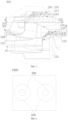
- a first height difference H1 is formed between the first flame holes 113 and the second flame holes 213.
- the first height difference H1 is greater than 15 mm and smaller than 40 mm.
- the first height difference H1 is greater than 40 mm, the first height difference H1 is too large, and thus a distance between the first burner 101 and the second burner 201 is too large, making it difficult to assist ignition of the second burner 201 by the flames from the first burner 101.
- the first height difference H1 is smaller than 15 mm, the first height difference H1 is too small, and accordingly the distance between the first burner 101 and the second burner 201 is too small, resulting in a poor heat dissipation effect. Therefore, internal heat of the burner assembly 300 is too high, easily causing safety hazards.
- an appropriate value should be selected for the first height difference H1 to ensure a normal operation and safe use of each of the first burner 101 and the second burner 201.
- the first height difference H1 may be greater than 15 mm and smaller than 40 mm, to ensure heat dissipation efficiency and flame transfer efficiency of the burner assembly 300, improving safety of the burner assembly 300.
- the first height difference H1 may be greater than 15 mm and smaller than 40 mm, i.e., 15 mm ⁇ H1 ⁇ 40mm.
- H1 may be 17 mm, 19 mm, 23 mm, 25 mm, 30 mm, 32 mm, 37 mm, or other value that is greater than 15 mm and smaller than 40 mm.
- the first height difference H1 is greater than 40 mm, the first height difference H1 is too large, and accordingly the distance between the first burner 101 and the second burner 201 is too large. Therefore, it is difficult to assist ignition of the second burner 201 by the flames from the first burner 101, reducing the ignition efficiency.
- the first height difference H1 is smaller than 15 mm, the first height difference H1 is too small, and accordingly the distance between the first burner 101 and the second burner 201 is too small, resulting in the poor heat dissipation effect. Therefore, the internal heat of the burner assembly 300 is too high, easily causing safety hazards.
- a first height difference H1 is formed between the first flame holes 113 and the second flame holes 213.
- the first height difference is greater than 20 mm and smaller than 30 mm.
- the ignition efficiency and the heat dissipation efficiency of the burner assembly 300 are further improved.
- the first height difference H1 is greater than 30 mm, the first height difference H1 is large, and accordingly the distance between the first burner 101 and the second burner 201 is large, resulting in low efficiency in assisting the ignition of the second burner 201 by the flames from the first burner 101.
- the first height difference H1 is smaller than 20 mm, the first height difference H1 is small, and accordingly the distance between the first burner 101 and the second burner 201 is small, resulting in the poor heat dissipation effect. Therefore, the internal heat of the burner assembly 300 is high, easily causing safety hazards.
- an appropriate value should be selected for the first height difference H1 to ensure the normal operation and safe use of each of the first burner 101 and the second burner 201.
- the first height difference H1 may be greater than 20 mm and smaller than 30 mm, to further improve the heat dissipation efficiency and the flame transfer efficiency of the burner assembly 300.
- the first height difference H1 may be greater than 20 mm and smaller than 30 mm, i.e., 20 mm ⁇ H1 ⁇ 30 mm.
- H1 may be 21 mm, 23 mm, 24 mm, 25 mm, 26 mm, 27 mm, 29 mm, or other value that is greater than 20 mm and smaller than 30 mm.
- the first height difference H1 is greater than 30 mm, the first height difference H1 is large, and accordingly the distance between the first burner 101 and the second burner 201 is large, resulting in the low efficiency in assisting the ignition of the second burner 201 by the flames from the first burner 101.
- the first height difference H1 is smaller than 20 mm, the first height difference H1 is small, and accordingly the distance between the first burner 101 and the second burner 201 is small, resulting in the poor heat dissipation effect. Therefore, the internal heat of the burner assembly 300 is high, easily causing safety hazards.
- a first height difference H1 is formed between the first flame holes 113 and the second flame holes 213.
- the first height difference H1 is 23.65 mm.
- the ignition efficiency and the heat dissipation efficiency of the burner assembly 300 are high, ensuring the safety of the burner assembly 300.
- the first height difference H1 may be 23.65 mm, i.e., a distance between the first flame holes 113 and the second flame holes 213 is 23.65 mm. Therefore, the first flame holes 113 can quickly assist the second flame holes 213 in igniting in a manner of flame upward spread when a suitable heat dissipation space is ensured to be formed between the first burner 101 and the second burner 201, improving the ignition efficiency and the heat dissipation efficiency of the burner assembly 300.
- the flames generated by the first burner 101 are transferred from the first flame holes 113 to the second flame holes 213 (from bottom to top), which allows for better ignition of the gas at the second flame holes 213 from the inner circumferential edge of the second burner 201 to form a double-ring flame to cover the pot bottom, making the ignition efficiency high.
- the heat dissipation space between the first burner 101 and the second burner 201 is suitable, which can ensure the smooth air circulation in the burner assembly 300. That is, the internal heat of the burner assembly 300 may be dissipated by air cooling, improving the heat dissipation efficiency and ensuring safe operation of the burner assembly 300.
- a depth direction of each first flame hole 113 is inclined relative to a radial direction of the first burner 101 to define a first deflection angle E.
- the first deflection angle E is greater than 0° and smaller than 45°.
- the flames at the first flame holes 113 spirally gather, to improve the flame intensity, ensuring the burning efficiency of the gas.
- the first deflection angle E may be an angle formed by inclination of the depth direction of each first flame hole 113 relative to a radial direction of the inner circumferential edge of the first burner 101, and may be used for adjusting a diameter of the annular flame, satisfying heating requirements for the central part of the pot bottom.
- a suitable angle should be selected for the first deflection angle E to allow the first flame holes 113 to form an annular flame with a suitable diameter. Therefore, the burning efficiency of the gas is improved to improve the flame intensity, further ensuring the heating amount at the central part of the pot bottom.
- the first deflection angle E may be greater than 0° and smaller than 45°, i.e., 0 ⁇ E ⁇ 45°. In some examples, the angle E may be 5°, 8°, 10°, 25°, 30°, 35°, 40°, or other value that greater than 0° and smaller than 45 0°.
- the first deflection angle E is greater than 45°, the first deflection angle E is too large, and accordingly the diameter of the annular flame formed by the first flame holes 113 is too large, causing the flames to be relatively adjacent to the edge of the pot bottom.
- the heating amount in the central part of the pot bottom is reduced.
- the heating amount at the edge of the pot bottom is increased, resulting in poor heating uniformity of the burner assembly 300 and a reduction in the burning efficiency of the gas.
- each first flame hole 113 is inclined relative to the radial direction of the first burner 101 to define a first deflection angle E.
- the first deflection angle E is greater than 0° and smaller than 30°.
- a suitable angle should be selected for the first deflection angle E to allow the first flame holes 113 to form an annular flame with a suitable diameter, to cover and heat the central part of the pot bottom, further improving the flame intensity and the heating effect.
- the first deflection angle E may be greater than 0° and smaller than 30°, i.e., 0° ⁇ E ⁇ 30°. In some examples, the first deflection angle E may be 3°, 5°, 8°, 10°, 15°, 25°, 27°, or other value that is greater than 0° and smaller than 30° 0° to 30°.
- the first deflection angle E is greater than 30°, the first deflection angle E is large, and accordingly the diameter of the annular flame formed by the first flame holes 113 is large. As a result, the flames are located relatively adjacent to the edge of the pot bottom, reducing the heating amount in the central part of the pot bottom. Correspondingly, the heating amount at the edge of the pot bottom is increased, resulting in poor heating uniformity of the burner assembly 300 and reduced burning efficiency of the gas.
- each first flame hole 113 is inclined relative to the radial direction of the first burner 101 to define a first deflection angle E.
- the first deflection angle E is 30°.
- the first deflection angle E may be 30°, i.e., an inclination angle of the depth direction of each first flame hole 113 relative to the radial direction of the first burner 101 is 30°, and accordingly the flames formed by the first flame holes 113 have a suitable heating area when the flames generated by the first burner 101 are ensured to gather spirally, providing high flame intensity and good heating effect of the first burner 101.
- the flames formed by the first flame holes 113 are distributed in a ring shape, which can better cover the central part of the pot bottom (a target heating region), providing high heating efficiency.
- the depth direction of each first flame hole 113 is inclined relative to the radial direction of the first burner 101, which can ensure an appropriate distance between the flames formed by the first flame holes 113 and the central part of the pot bottom, and thus the flame intensity is increased.
- the flames formed by the first flame holes 113 extend spirally upwards, which allows the flames to overlap and gather to the central part of the pot bottom, ensuring increased flame intensity.
- a depth direction of each second flame hole 213 is inclined relative to a radial direction of the second burner 201 to define a second deflection angle F.
- the second deflection angle F is greater than 0° and smaller than 45°.
- the flames at the second flame holes 213 spirally gather, to improve the flame intensity, ensuring the burning efficiency of the gas.
- the second deflection angle F may be an angle formed by inclination of the depth direction of each second flame hole 213 relative to a radial direction of the inner circumferential edge of the second burner 201, and may be used for adjusting a diameter of the outer ring flame, satisfying heating requirements for the edge of the pot bottom.
- a suitable angle should be selected for the second deflection angle F to allow the second flame holes 213 to form an outer ring flame with a suitable diameter. Therefore, the burning efficiency of the gas is improved to improve the flame intensity, further ensuring the heating amount of the edge of the pot bottom.
- the second deflection angle F may be greater than 0° and smaller than 45°, i.e., 0 ⁇ F ⁇ 45°. In some examples, F may be 5°, 8°, 10°, 25°, 30°, 35°, 40°, or other value that is greater than 0° and smaller than 45°.
- the second deflection angle F is greater than 45°, the second deflection angle F is too large, and accordingly the diameter of the outer ring flame formed by the second flame holes 213 is too large. As a result, the outer ring flames extend to a position outside the pot bottom. Therefore, the heating amount at the edge of the pot bottom is reduced, providing poor heating uniformity of the burner assembly 300 and recued burning efficiency of the gas.
- each second flame hole 213 is inclined relative to the radial direction of the second burner 201 to define a second deflection angle F.
- the second deflection angle F is greater than 0° and smaller than 30°.
- a suitable angle should be selected for the second deflection angle F to allow the second flame holes 213 to form an outer ring flame with a suitable diameter, to cover and heat the edge of the pot bottom, further improving the flame intensity and the heating effect.
- the second deflection angle F may be greater than 0° and smaller than 30°, i.e., 0 ⁇ F ⁇ 30°. In some examples, F may be 3°, 5°, 8°, 10°, 15°, 25°, 27°, or other value that is greater than 0° and smaller than 30°.
- the second deflection angle F is greater than 30°, the second deflection angle F is large, and accordingly the diameter of the outer ring flame formed by the second flame holes 213 is large. As a result, the outer ring flames extend to the position outside the pot bottom. Therefore, the heating amount at the edge of the pot bottom is reduced, providing poor heating uniformity of the burner assembly 300 poor and reduced burning efficiency of the gas.
- each second flame hole 213 is inclined relative to the radial direction of the second burner 201 to define a second deflection angle F.
- the second deflection angle F is 30°.
- the flame intensity is high and the heating efficiency is significant while ensuring the flame gathering of the second flame holes 213.
- the second deflection angle F may be 30°, i.e., an inclination angle of the depth direction of each second flame hole 213 relative to the radial direction of the second burner 201 is 30°.
- the flames formed by the second flame holes 213 have a suitable heating area when the flames generated by the second burner 201 are ensured to gather spirally, providing high flame intensity and significant heating effect of the second burner 201 high.
- the flames formed by the second flame holes 213 are distributed in a ring shape, which can better cover the edge of the pot bottom (the target heating region), and thus the heating efficiency is high.
- the depth direction of each second flame hole 213 is inclined relative to the radial direction of the first burner 101, which can ensure an appropriate distance between the flame formed by the second flame holes 213 and the edge of the pot bottom, and thus the flame intensity is large.
- the flames formed by the second flame holes 213 extends spirally upwards, which allows the flames to overlap and gather at the edge of the pot bottom, ensuring the flame intensity is large.
- the burner assembly 300 includes a deflector 50 disposed between the first burner 101 and the second burner 201.
- a second height difference H2 is formed between the deflector 50 and a top of each first flame hole 311.
- a third height difference H3 is formed between the deflector 50 and a bottom of each second flame hole 213. The third height difference H3 is greater than the second height difference H2.
- the first burner 101 or the second burner 201 is kept at a suitable distance from the deflector 50, to improve air flowability inside the burner assembly 300, improving the burning efficiency of the burner assembly 300.
- the deflector 50 is of a funnel shape and disposed between the first burner 101 and the second burner 201. Further, the deflector 50 has a large opening end adjacent to the bottom of each second flame hole 213 and a small opening adjacent to the top of each first flame hole 113, to increase spaces of the first burner 101 and the second burner 201. In this way, the secondary air supply is ensured, improving the burning efficiency of the burner assembly 300.
- the second height difference H2 may be the distance between the deflector 50 and the top of each first flame hole 113. The smaller the second height difference H2, the faster a secondary air reaches the first flame holes 113, ensuring burning efficiency of the first burner 101.
- the third height difference H3 may be the distance between the deflector 50 and the bottom of each second flame hole 213, to ensure that the secondary air quickly passes into the interior of the burner assembly 300, improving the burning efficiency of the burner assembly 300.
- the third height difference H3 is greater than the second height difference H2, which ensures a large distance between the deflector 50 and the bottom of each second flame hole 213, allows the secondary air to quickly pass into the interior of the burner assembly 300, and can provide the interior of the burner assembly 300 with sufficient secondary air.
- the third height difference H3 is greater than the second height difference H2, which ensures that the distance between the deflector 50 and the top of each first flame hole 113 is small, and allows for a short delivery distance of the secondary air in the interior of the burner assembly 300 at a fast delivery speed, improving the burning efficiency of the burner assembly 300.
- the deflector 50 is of a funnel shape and disposed between the first burner 101 and the second burner 201. Such a design may also be used for guiding oil droplets generated during the cooking to flow into the oil cup (not shown) along a side wall of the deflector 50, to improve a cleanliness degree of the burner assembly 300.
- the second height difference H2 is greater than 0 mm and smaller than 8 mm.
- the top of the first burner 101 is kept at a suitable distance from the deflector 50 to improve the secondary air supply, improving the burning efficiency of the first burner 101.
- an appropriate value should be selected for the second height difference H2 to ensure a supply speed of the secondary air to the first flame holes 113, improving the burning efficiency of the first burner 101.
- the second height difference H2 may be greater than 0 mm and smaller than 8 mm to provide sufficient secondary air timely and ensure full burning of the gas at the first flame holes 113, improving the burning efficiency of the first burner 101.
- the second height difference H2 may be greater than 0 mm and smaller than 8 mm, i.e., 0 ⁇ H2 ⁇ 8 mm.
- H2 may be 1 mm, 2 mm, 3 mm, 4 mm, 5 mm, 6 mm, 7 mm, or other value that is greater than 0 mm and smaller than 8 mm.
- the second height difference H2 is greater than 8 mm, the second height difference H2 is too large, and thus the secondary air needs too long time to reach the first flame holes 113, resulting in the reduction of the burning efficiency of the first burner 101 and low flame uniformity.
- the second height difference H2 is 5 mm.
- the secondary air supply is sufficient, and thus the burning efficiency of the first burner 101 is high.
- the second height difference H2 may be 5 mm, i.e., the distance between the top of each first flame hole 113 and the deflector 50 is 5 mm, and thus the secondary air can quickly reach the first flame holes 113 while ensuring an appropriate distance between the top of the first burner 101 and the deflector 50. In this way, the burning efficiency of the first burner 101 is high.
- the gas at the first flame holes 113 may be sufficiently burned by the secondary air, and thus the burning efficiency of the first burner 101 is high, further improving the flame intensity.
- the second height difference H2 is 5 mm
- a distance between the first burner 101 and the deflector 50 is large with high heat dissipation efficiency, ensuring the safe operation of the burner assembly 300.
- the third height difference H3 is greater than 0 mm and smaller than 15 mm.
- the bottom of the second burner 201 is kept at an appropriate distance from the deflector 50 to improve the secondary air supply, improving the burning efficiency and ensuring the flame uniformity of the burner assembly 300.
- an appropriate distance should be selected for the third height difference H3, and accordingly sufficient secondary air can be supplied into the interior of the burner assembly 300 while ensuring that the gas from the second flame holes 213 is fully burned, ensuring the flame uniformity of the burner assembly 300.
- the third height difference H3 may range from 0 mm to 15 mm, i.e., 0 mm ⁇ H3 ⁇ 15 mm.
- H3 may be 1 mm, 3 mm, 4 mm, 7 mm, 9 mm, 10 mm, 13 mm, or other values ranging from 0 mm to 15 mm.
- the third height difference H3 is greater than 15 mm, the third height difference H3 is too large, and accordingly the distance between a deflector 50 and each second flame hole 213 is too large, resulting in a reduction in the stability. As a result, the deflector 50 and the second flame holes 213 are not easily fixed.
- the third height difference H3 is too large, making a volume of the burner assembly 300 large and an occupied space large.
- the third height difference H3 is 9 mm.
- the secondary air supply is sufficient, and thus the burning efficiency of the burner assembly 300 is high and the flame uniformity is good.
- the third height difference H3 may be 9 mm, i.e., the distance between the bottom of each second flame hole 213 and the deflector 50 is 9 mm, which allows the secondary air to be sufficiently supplied into the interior of the burner assembly 300 when the gas from the second flame holes 213 is ensured to be fully burned. Therefore, the burning efficiency of the first burner 101 is high, further ensuring the better flame uniformity of the burner assembly 300.
- the gas at the second flame holes 213 may be sufficiently burned by the secondary air. Therefore, the burning efficiency of the second burner 201 is high, further improving the flame intensity.
- sufficient secondary air may quickly enter the interior of the burner assembly 300 by means of the third height difference H3 to accelerate air flow and a heat dissipation rate. Meanwhile, sufficient secondary air may also reach the first flame holes 113 along the side wall of the deflector 50, to allow the gas at the first flame holes 113 to be fully burned, ensuring the high burning efficiency of the burner assembly 300 and the better flame uniformity.
- the first lower plate 122 is depressed downwardly to form the first lower hole channels 125.
- the first upper plate 133 is arched upwardly to form the first upper hole channels 135.
- the first lower hole channels 125 and the first upper hole channels 135 directly face towards each other to form the first flame holes 113 of the first burner 101.
- the first upper hole channels 135 of the first upper plate 133 directly face towards the first lower hole channels 125 of the first lower plate 122 to allow the first flame holes 113 of the first burner 101 to be formed in such a manner that the first flame holes 113 directly face towards each other. In this way, a total area of the flame holes of the first burner 101 is increased. Further, a flame intensity and an upper load limit of the first burner 101 are increased.
- the first lower plate 122 may be used for forming the first flame holes 113. Therefore, the first lower plate 122 may be a high-temperature and corrosion-resistant material.
- the first lower plate 122 may be made of an aluminum alloy material to ensure bending performance of the first lower plate 122, ensuring the formation of the first lower hole channels 125. In other embodiments, the first lower plate 122 may be made of other materials, which is not specifically limited herein.
- the first upper plate 133 may be used with the first lower plate 122 for forming the first flame holes 113. Therefore, the first upper plate 133 may be made of a high-temperature and corrosion-resistant material.
- the first upper plate 133 may be made of the same material as the first lower plate 122 to ensure bending performance of the first upper plate 133, ensuring the formation of the first upper hole channels 135. In other embodiments, the first upper plate 133 may be made of other materials, which is not specifically limited herein.
- first lower hole channels 125 directly face towards the first upper hole channels 135 to form first flame holes 113 of a circular ring shape. Compared to first lower hole channels 125 in a misaligned arrangement or first upper hole channels 135 in a misaligned arrangement, the total area of the first flame holes 113 is increased, which can increase gas burning amount, increasing the flame intensity of the first burner 101.
- an equivalent cross-sectional area of the first flame holes 113 of the invention remains unchanged, which can ensure that the first burner 101 has excellent flame transfer and flame stabilization effects while generating intense flames.
- the second lower plate 222 is depressed downwardly to form the second lower hole channels 225.
- the second upper plate 233 is arched upwardly to form the second upper hole channels 235.
- the second lower hole channels 225 and the second upper hole channels 235 directly face towards each other to form the second flame holes 213 of the second burner 201.
- the second upper hole channels 235 of the second upper plate 233 directly face towards the second lower hole channels 225 of the second lower plate 222, to allow the second flame holes 213 of the second burner 201 to be formed in such a manner that the second flame holes 213 directly face towards each other. In this way, the total area of the flame holes of the second burner 201 is increased. Further, the flame intensity and the upper load limit of the second burner 201 are increased.
- the second lower plate 222 may be used for forming the second flame holes 213. Therefore, the second lower plate 222 may be made of a high-temperature and corrosion-resistant material.
- the second lower plate 222 may be made of an aluminum alloy material to ensure bending performance of the second lower plate 222, ensuring the formation of the second lower hole channels 225.
- the second first lower plate 222 may be made of other materials, which is not specifically limited herein.
- the second upper plate 233 may be used with the second lower plate 222 for forming the second flame holes 213. Therefore, the second upper plate 233 may be made of a high-temperature and corrosion-resistant material.
- the second upper plate 233 may be made of the same material as the second lower plate 222 to ensure the bending performance of the second upper plate 233, ensuring the formation of the second upper hole channels 235. In other embodiments, the second upper plate 233 may be made of other materials, which is not specifically limited herein.
- the second lower hole channels 225 directly face towards the second upper hole channels 235 to form the second flame holes 213 of a circular ring shape.
- the total area of the second flame holes 213 is increased, which can increase the higher gas burning amount, increasing the flame intensity of the second burner 201.
- an equivalent cross-sectional area of the second flame holes 213 of the invention remains unchanged, which can ensure that the second burner 201 has excellent flame transfer and flame stabilization effects while generating intense flames.
- first flame transfer gaps 155 are formed between the first upper plate 133 and the first partition 143. Two adjacent first flame holes 113 are in communication with each other via the corresponding first flame transfer gap 155.
- the first flame transfer gaps 155 are formed between the first upper plate 133 and the first partition 143 to ensure that a communicable gap is formed between two adjacent first upper hole channels 135 at the first upper plate 133, and thus flame transfer and flame stabilization can be provided.
- first burner 101 During continuous operation of the first burner 101, it is ensued that, by communicating two adjacent first upper hole channels 135 via the corresponding first flame transfer gap 155 and continuously supplementing the secondary air, the gases from the two adjacent first upper hole channels 135 are adequately burned, allowing the first burner 101 to form an integrated continuous flame. In this way, a high flame intensity and good stability are ensured. Further, the resistance of the separation of the flames from flame holes of the first burner 101 is improved to achieve the flame stabilization.
- each first flame transfer gap 155 may range from 0.50 mm to 0.80 mm. In this way, two adjacent independent first upper hole channels 135 are communicated with each other, to ensure the flame transfer capability and flame stabilization capability of the first burner 101.
- each first flame transfer gap 155 is greater than 0.50 mm and smaller than 0.80 mm.
- each first flame transfer gap 155 may be 0.50 mm, 0.57 mm, 0.62 mm, 0.68 mm, 0.70 mm, 0.71 mm, 0.80 mm, or other value ranging from 0.50 mm to smaller than 0.80 mm.
- each first flame transfer gap 155 is smaller than 0.50 mm, each first flame transfer gap 155 is too small, resulting in low flame transfer efficiency and low secondary air supplement efficiency. In this way, the flame transfer capability of the first burner 101 is poor.
- each first flame transfer gap 155 is greater than 0.80 mm, each first flame transfer gap 155 is too large, resulting in low flame stability. In this case, the resistance of the separation of the flames from the flame holes of the first burner 101 is poor, easily resulting in a flame-out and extinguishment phenomenon.
- second flame transfer gaps 255 are formed between the second upper plate 233 and the second partition 243. Two adjacent second flame holes 213 are in communication with each other via the corresponding second flame transfer gap 255.
- the second flame transfer gaps 255 are formed between the second upper plate 233 and the second partition 243 to ensure that a communicable gap is formed between two adjacent second upper hole channels 235 at the second upper plate 233, and thus flame transfer and flame stabilization can be provided.
- the second burner 201 may be ignited by the flames generated by the first burner 101 in a manner of flame upward spread, to ignite the gas at the second flame holes 213, and flames are transferred to two adjacent second upper hole channels 235 through the corresponding second flame transfer gap 255. In this way, a continuous flame is formed. Further, the flame transfer efficiency and the ignition success rate are ensured.
- each second flame transfer gap 255 may range from 0.50 mm to 0.80 mm. In this way, two adjacent independent second upper hole channels 235 are communicated with each other, to ensure the flame transfer capability and flame stabilization capability of the second burner 201.
- each second flame transfer gap 255 ranges from 0.50 mm to 0.80 mm.
- each second flame transfer gap 255 may be 0.50 mm, 0.57 mm, 0.62 mm, 0.68 mm, 0.70 mm, 0.71 mm, 0.80 mm, or other value ranging from 0.50 mm to 0.80 mm.
- each second flame transfer gap 255 is smaller than 0.50 mm, the second flame transfer gap 255 is too small, resulting in low flame transfer efficiency and low secondary air supplement efficiency. In this way, the flame transfer capability of the second burner 201 is poor.
- each second flame transfer gap 255 is greater than 0.80 mm, the second flame transfer gap 255 is too large, resulting in low flame stability. In this way, the resistance to the separation of the flames from the flame holes of the second burner 201 is poor, easily resulting in the flame-out and extinguishment phenomenon.
- the burner assembly 300 further includes an ignition device 501.
- the ignition device 501 includes an ignition needle 503, a thermocouple 504, and a first support 505.
- the ignition needle 503 and the thermocouple 504 are fixed to the first support 505.
- the ignition needle 503 of the ignition device 501 is arranged adjacent to the first flame holes 113.
- the ignition needle 503 and the thermocouple 504 are integrated into one piece in the ignition device 501.
- the ignition needle 503 can be positioned adjacent to the first flame holes 113 and located inside the burner assembly 300, to improve ignition success rates of the first burner 101 and the second burner 201 and simplify mounting.
- each of the first burner 101 and the second burner 201 includes a burner body and a deflector 50.
- the burner body has a gas channel 30h formed in the burner body.
- the burner body has inner ring flame holes 30a in communication with the gas channel 30h and outer ring flame holes 30f in communication with the gas channel 30h.
- the outer ring flame holes 30f are arranged around the inner ring flame holes 30a.
- the burner body further has an air supplement channel 30c independent of the gas channel 30h.
- the air supplement channel 30c includes an air inlet 30d located at an outer side wall of the burner body and an air outlet 30k located between the inner ring flame holes 30a and the outer ring flame holes 30f.
- the deflector 50 is disposed at the air outlet 30k.
- the deflector 50 is engaged with an inner wall of the air supplement channel 30c to define an inner-ring air supplement opening 30i for supplementing air to flow towards the inner ring flame holes 30a and an outer-ring air supplement opening 30j for supplementing air to flow towards the outer ring flame holes 30f.
- an embodiment of the invention provides a cooker 1000.
- the cooker 1000 includes the burner assembly 300 according to any one of the above embodiments.
- the second burner 201 is disposed above the first burner 101 and has the inner diameter D2 greater than the inner diameter D1 of the first burner. Therefore, when the first burner 101 is successfully ignited, the second burner 201 can be ignited from an inner circumference of the second burner 201 in a manner of flame upward spread, to ensure the flame uniformity at the pot bottom.
- This design is simple in structure, and convenient and quick.
- the cooker 1000 may be a natural gas cooker, a liquefied gas cooker, or a coal gas cooker.
- the cooker 1000 includes a burner assembly 300.
- the burner assembly 300 includes at least one burner, such as a single inner ring burner, a single outer ring burner, a double-ring inner flame burner, or a multi-ring inner flame burner.
- the cooker 1000 includes a stove 200.
- the stove 200 includes a burner assembly 300.
- the burner assembly 300 includes at least one burner.
- the cooker 1000 may be a single-stove cooker, a double-stove cooker, or a multi-stove cooker.
- FIG. 6 is a schematic structural view of a double-stove cooker.
- the stove 200 includes a burner assembly 300.
- the burner assembly 300 may be an outer ring burner, an inner ring burner, or a double ring burner formed by combining the outer ring burner and the inner ring burner, which is not specifically limited herein.
- the ignition needle and the thermocouple are separately disposed at inner and outer sides of the burner, which is cumbersome to mount, with a low ignition success rate.
- an embodiment of the invention provides a burner assembly 300 and a cooker 1000, which can improve ignition success rates of the first burner and the second burner, and are easily mounted.
- the burner assembly 300 and the cooker 1000 according to the embodiments of the invention are described in detail below with reference to FIG. 7 to FIG. 15 .
- the burner assembly 300 includes a first burner 101, a second burner 201, and an ignition device 501.
- the first burner 101 is of a ring shape and has first flame holes 113 formed on an inner circumferential edge of the first burner 101.
- the second burner 201 is of a ring shape and has second flame holes 213 formed on an inner circumferential edge of the second burner 201.
- the second burner 201 is disposed above the first burner 101 and has an inner diameter D2 greater than an inner diameter D1 of the first burner.
- the ignition device 501 includes an ignition needle 503, a thermocouple 504, and a first support 505.
- the ignition needle 503 and the thermocouple 504 are fixed to the first support 505.
- the ignition needle 503 of the ignition device 501 is arranged adjacent to the first flame holes 113.
- the ignition needle 503 and the thermocouple 504 are integrated into one piece in the ignition device 501.
- the ignition needle 503 can be positioned adjacent to the first flame holes 113 and located inside the burner assembly 300, to improve ignition success rates of the first burner 101 and the second burner 201 and simplify mounting.
- the first burner 101 may be an inner ring burner for providing an inner ring flame to ensure a flame intensity and heating uniformity at a central part of the pot bottom.
- a plurality of first flame holes 113 are formed on the inner circumferential edge of the first burner 101, to ensure that the plurality of first flame holes 113 are arranged around the inner circumferential edge of the first burner 101 to be formed as an inner ring flame outlet to provide an inner annular flame. In this way, heating uniformity at the central part of the pot bottom is ensured.
- the second burner 201 may be an outer ring burner for providing an outer ring flame to ensure a flame intensity and heating uniformity at an edge of the pot bottom.
- a plurality of second flame holes 213 are formed on the inner circumferential edge of the second burner 201, to ensure that the plurality of second flame holes 213 are arranged around the inner circumferential edge of the second burner 201 to be formed as an outer ring flame outlet to provide an outer annular flame. In this way, the heating uniformity at the edge of the pot bottom is ensured.
- the inner diameter D1 of the first burner may be a diameter of the inner circumferential edge of the first burner 101, to provide an inner ring flame of a diameter of D1.
- the inner diameter D2 of the second burner may be a diameter of the inner circumferential edge of the second burner 201, to provide an outer ring flame of a diameter of D2.
- the inner diameter D2 of the second burner is greater than the inner diameter D1 of the first burner, to ensure that the first burner 101 provides the inner ring flame and the second burner 201 provides the outer ring flame in such a manner that inner ring flame and the out ring flame cooperate with each other. In this way, it is ensured that the central part and the edge of the pot bottom are uniformly heated, allowing the entire pot bottom to be uniformly heated, further ensuring the flame uniformity at the pot bottom.
- the ignition device 501 may be used for providing an electric discharge arc to ensure normal ignition of the burner assembly 300 and detecting a change in thermoelectric potential to ensure safe use of the burner assembly 300.
- the ignition needle 503 is disposed adjacent to the first flame holes 113 on the first support 505 for providing an electric discharge arc to ignite a gas at the first flame holes 113 to form an inner ring flame. Meanwhile, the inner ring flame is upwardly burned to ignite a gas at the second flame holes 213, ensuring efficient ignition of the burner assembly 300, which is convenient and quick.
- thermocouple 504 is spaced apart from the ignition needle 503 and fixed on the first support 505, to be in contact with and detect the flames generated at the first flame holes 113.
- thermocouple 504 functions as a sensor that may control an on-off of a gas passage. When the flames are accidentally extinguished due to overflowing during porridge cooking, overflowing during water heating, or the like, the thermocouple 504 may automatically cut off a gas source, preventing gas leakage to provide a flame-out protection function.
- the ignition needle 503 is disposed adjacent to the first flame holes 113 and located inside the burner assembly 300 for providing the electric discharge arc, to ignite the gas at the first flame holes 113 to form an inner annular flame.
- the gas at the second flame holes 213 may be ignited by the inner annular flames generated at the first flame holes 113 from the inner circumference of the second flame holes 213 in a manner of flame upward spread, to form an outer annular flame. In this way, the flame uniformity of the burner assembly 300 is ensured, which is convenient and quick and provides high ignition efficiency.
- the ignition device 501 is disposed inside the burner assembly 300. In this way, accidental damages resulting from collisions and water overflow of the pot bottom can be reduced. In addition, the ignition device 501 can ignite normally, improving an ignition success rate of the ignition device 501.
- the ignition needle 503 and the thermocouple 504 are integrated in the ignition device 501, which can ensure that the burner assembly 300 is efficient in ignition, occupies a small space, and is convenient to be mounted.
- the first burner 101 may be stably disposed at an appropriate distance from the second burner 201, to ensure smooth air circulation at the first flame holes 113 inside the burner assembly 300, ensuring normal operation of the first burner 101 and avoiding an insufficient intensity (or extinguishment) of the inner ring flames due to insufficient secondary air supplement. Therefore, the flame uniformity of the entire pot bottom is ensured.
- the ignition device 501 is disposed between the first burner 101 and the second burner 201.
- the ignition device 501 is disposed inside the burner assembly 300 to avoid damage due to accidental collisions, improving stability and ignition efficiency of the ignition device 501.
- the ignition device 501 is disposed between the first burner 101 and the second burner 201, which can reduce an influence of an external environment on the ignition process and ensure the normal operation of the ignition needle 503.
- the external environment may be an accidental collision, an unexpected liquid spill, or the like, and may cause the ignition needle 503 to be damaged and fail to ignite normally.
- the ignition device 501 is disposed between the first burner 101 and the second burner 201 to ensure the stability of the ignition needle 503, providing a suitable ignition environment to achieve efficient ignition.
- the ignition device 501 may be disposed adjacent to the first flame holes 113 of the first burner 101. In this way, the first burner 101 can be ignited quickly to ignite the gas at the second flame holes 213 of the second burner 201 in a manner of flame upward spread. Therefore, the ignition success rate of the burner assembly 300 is improved.
- an angle ⁇ of a length direction of the ignition needle 503 relative to a central axis of the first burner 101 is greater than 30° and smaller than 90°.
- the ignition needle 503 can be positioned adjacent to the first flame holes 113 above the inner circumferential edge of the first burner 101 to ignite the gas at the first flame holes 113. Therefore, the ignition success rate is improved.
- the ignition needle 503 should be disposed at an appropriate angle ⁇ , to ensure that the gas at the first flame holes 113 can be quickly ignited by the electric discharge arc accurately. Therefore, the ignition success rate is improved.
- an angle ⁇ of the length direction of the ignition needle 503 relative to the central axis of the first burner 101 is greater than 30° and smaller than 90°, to ensure the normal ignition of the burner assembly 300.
- the angle ⁇ may be greater than 30° and smaller than 90°, i.e., 30° ⁇ 90°.
- ⁇ may be 35°, 40°, 45°, 60°, 65°, 70°, 85°, or other value that is greater than 30° and smaller than 90°.
- the angle ⁇ is greater than 90°, the angle ⁇ is too large, and thus a tip end of the ignition needle 503 is inclined towards the second burner 201, resulting in a too large space between the first burner 101 and the second burner 201 and thus a too large distance between the first flame holes 113 and the second flame holes 213. That is, an effect of the inner ring flames generated at the first flame holes 113 on the ignition of the gas at the second flame holes 213 is poor, resulting in poor ignition efficiency.
- a distance between the inner ring flames and the pot bottom is exactly different from a distance between the outer ring flames and the pot bottom, and thus different flame intensities of the pot bottom are provided, reducing the flame uniformity.
- the angle ⁇ is smaller than 30°, the angle ⁇ is too small, and thus the tip end of the ignition needle 503 is deviated from the first flame holes 113 and is directed upwardly. In this case, an electric arc generated by the ignition needle 503 is far away from the first flame holes 113. As a result, the electric arc is not easily guided to the first flame holes 113, reducing the ignition success rate.
- an angle ⁇ of the length direction of the ignition needle 503 relative to the central axis of the first burner 101 is greater than 60° and smaller than 70°.
- the angle ⁇ of the length direction of the ignition needle 503 relative to the central axis of the first burner 101 is greater than 60° and smaller than 70°, which allows for a high ignition success rate of the ignition needle 503, ensuring rapid and efficient ignition of the first burner 101.
- the angle ⁇ may be greater than 60° and smaller than 70°, i.e., 60° ⁇ ⁇ ⁇ 70°.
- ⁇ may be 61°, 63°, 64°, 65°, 67°, 68°, 69°, or other value that is greater than 60° and smaller than 70° 60° to 70°.
- the angle ⁇ is greater than 70°, the angle ⁇ is large, which allows for a large space between the first burner 101 and the second burner 201, resulting in a far distance between the first flame holes 113 and the second flame holes 213. That is, the effect of the inner ring flames generated at the first flame holes 113 on the ignition of the gas at the second flame holes 213 is poor, resulting in the poor ignition efficiency.
- the distance between the inner ring flame and the pot bottom is exactly different from the distance between the outer ring flame and the pot bottom, which allows for different flame intensities of the pot bottom, reducing the flame uniformity.
- the angle ⁇ is smaller than 60°, the angle ⁇ is small, and thus the tip end of the ignition needle 503 is deviated from the first flame holes 113 and is directed upwardly. In this case, the electric arc generated by the ignition needle 503 is far away from the first flame holes 113. As a result, the electric arc is not easily guided to the first flame holes 113, reducing the ignition success rate.
- the ignition module 501 is disposed at inside the first burner 101.
- the ignition needle 503 is located adjacent to the first flame holes 113 from a position below the inner circumferential edge of the first burner 101 to ignite the gas at the first flame holes 113. Therefore, the ignition success rate is improved.
- the ignition device 501 is disposed inside the first burner 101, i.e., the ignition device 501 is located adjacent to the first flame holes 113 from a position below the inner circumferential edge of the first burner 101. In this way, the influence of accidental collisions or unexpected liquid spills on the ignition process can be reduced, ensuring the normal operation of the ignition needle 503.
- the ignition device 501 is disposed inside the first burner 101, to improve the stability of the ignition needle 503. As a result, a stable ignition environment is provided to achieve efficient ignition.
- the ignition device 501 is disposed adjacent to the first flame holes 113 of the first burner 101. In this way, the first burner 101 can be ignited quickly to ignite the gas at the second flame holes 213 of the second burner 201 in a manner of flame upward spread. Therefore, the ignition success rate of the burner assembly 300 is improved.
- the ignition device 501 is disposed inside the first burner 101, allowing for a more beautiful and tidy appearance of the burner assembly 300.
- the first support 505 includes a fixing sheet 531 and two groups of elastic sheets 532 extending from the fixing sheet 531.
- An engagement groove 533 is formed on each group of elastic sheets 532.
- the ignition needle 503 and the thermocouple 504 are fixed in the respective engagement grooves 533.
- the fixing sheet 531 may be a support bottom plate for supporting and fixing the ignition needle 503 and the thermocouple 504, to improve stability of the ignition device 501.
- the elastic sheets 532 may be two arc-shaped metal sheets to form engagement grooves 533 for catching. In this way, it can be ensured that the ignition needle 503 and the thermocouple 504 are respectively caught in the respective engagement grooves 533, improving the stability of the ignition device 501.
- each elastic sheet 532 is disposed on the support 22 at a predetermined angle.
- the tip end of the ignition needle 503 can be disposed adjacent to a tip end of the thermocouple 504, and the tip end of the ignition needle 503 can be disposed away from the tip end of the thermocouple 504. Therefore, it is ensured that the ignition needle 503 and the thermocouple 504 are located close to the first flame holes 113, which further ensures the normal ignition and flame-out protection of the burner assembly 300.
- the ignition needle 503 and the thermocouple 504 are integrated on the first support 505 to improve mounting efficiency. Meanwhile, the efficient ignition and flame-out protection of the burner assembly 300 can be ensured, improving the safety of the burner assembly 300.
- the first burner 101 includes a first lower plate 122, a first upper plate 133 disposed above the first lower plate 122, and a first partition 143.
- the first lower plate 122 has first lower hole channels 125.
- the first upper plate 133 has first upper hole channels 135 corresponding to the first lower hole channels 125.
- the first lower hole channels 125 and the first upper hole channels 135 directly face towards each other to form the first flame holes 113.
- the first partition 143 is disposed between the first lower plate 122 and the first upper plate 133 and separates the first lower hole channels 125 from the first upper hole channels 135.
- the first upper hole channels 135 of the first upper plate 133 directly face towards the first lower hole channels 125 of the first lower plate 122 to allow the first flame holes 113 of the first burner 101 to be formed in such a manner that the first flame holes 113 directly face towards each other. In this way, a total area of the flame holes of the first burner 101 is increased. Further, a flame intensity and an upper load limit of the first burner 101 are increased.
- the first lower plate 122 may be used for forming the first flame holes 113. Therefore, the first lower plate 122 may be a high-temperature and corrosion-resistant material.
- the first upper plate 133 may be made of the same material as the first lower plate 122 to ensure bending performance of the first upper plate 133, such that the first upper plate 133 is arched upwardly to form the first upper hole channels 135.
- the first upper plate 133 may be made of other materials, which is not specifically limited herein.
- first lower hole channels 125 directly face towards the first upper hole channels 135 to form first flame holes 113 of a circular ring-like shape.
- first lower hole channels 125 in a misaligned arrangement or first upper hole channels 135 in a misaligned arrangement the total area of the first flame holes 113 is increased, which can increase gas burning amount, increasing the flame intensity of the first burner 101.
- an equivalent cross-sectional area of the first flame holes 113 of the invention remains unchanged, which can ensure that the first burner 101 has excellent flame transfer and flame stabilization effects while generating intense flames.
- the protrusion 141 is disposed on the first partition 143 for attracting the electric arc generated by the ignition needle 503.
- a gas at the protrusion 141 can be ignited by the electric arc to form the flames. Therefore, a discharge arc of the ignition needle 503 can be prevented from deviating from the first partition 143, increasing the ignition success rate of the first burner 101.
- the second burner 201 includes a second lower plate 222, a second upper plate 233 disposed above the second lower plate 222, and a second partition 243.
- the second lower plate 222 has second lower hole channels 225.
- the second upper plate 233 has second upper hole channels 235 corresponding to the second lower hole channels 225.
- the second lower hole channels 225 and the second upper hole channels 235 directly face towards each other to form second flame holes 213.
- the second partition 243 is disposed between the second lower plate 222 and the second upper plate 233 and separates the second lower hole channels 225 from the second upper hole channels 235.
- the second upper hole channels 235 of the second upper plate 233 directly face towards the second lower hole channels 225 of the second lower plate 222, to allow the second flame holes 213 of the second burner 201 to be formed in such a manner that the second flame holes 213 directly face towards each other. In this way, the total area of the flame holes of the second burner 201 is increased. Further, the flame intensity and the upper load limit of the second burner 201 are increased.
- the second lower plate 222 may be used for forming the second flame holes 213. Therefore, the second lower plate 222 may be made of a high-temperature and corrosion-resistant material.
- the second lower plate 222 may be made of an aluminum alloy material to ensure bending performance of the second lower plate 222, ensuring the formation of the second lower hole channels 225.
- the second first lower plate 222 may be made of other materials, which is not specifically limited herein.
- the second upper plate 233 may be used with the second lower plate 222 for forming the second flame holes 213. Therefore, the second upper plate 233 may be made of a high-temperature and corrosion-resistant material.
- the second upper plate 233 may be made of the same material as the second lower plate 222 to ensure the bending performance of the second upper plate 233, ensuring the formation of the second upper hole channels 235. In other embodiments, the second upper plate 233 may be made of other materials, which is not specifically limited herein.
- the second lower hole channels 225 directly face towards the second upper hole channels 235 to form the second flame holes 213 of a circular ring shape.
- the total area of the second flame holes 213 is increased, which can increase the higher gas burning amount, increasing the flame intensity of the second burner 201.
- an equivalent cross-sectional area of the second flame holes 213 of the invention remains unchanged, which can ensure that the second burner 201 has excellent flame transfer and flame stabilization effects while generating intense flames.
- the inner diameter D2 of the second burner is 1.2 times to 2.5 times the inner diameter D1 of the first burner.
- the inner diameter of the first burner may be set as D1, to ensure that the annular flames generated by the first burner 101 may be better located at the central part of the pot bottom, to improve the flame intensity at the central part of the pot bottom. Meanwhile, it is ensured that the central part of the pot bottom is heated uniformly.
- the inner diameter D2 of the second burner is 1.2 times to 2.5 times the inner diameter D1 of the first burner, to ensure that the flames generated by the burner assembly 300 can heat the pot bottom uniformly, improving a gas utilization rate and the cooking efficiency.
- the inner diameter of the first burner 101 is D1
- the inner diameter D2 of the second burner may is greater than 1.2D1 and smaller than 2.5D1.
- the flames generated by the second burner 201 can better cover the edge of the pot bottom, ensuring that the central part and the edge of the pot bottom are uniformly heated, improving the cooking efficiency.
- the inner diameter D2 of the second burner satisfies 2.5D1 >D2> 1.2D1.
- the inner diameter D2 of the second burner may be 1.3D1, 1.5D1, 1.6D1, 1.9D1, 2.0D1, 2.3D1, 2.4D1, or other value that is greater than 1.2D1 and smaller than 2.5D1.
- the inner diameter D2 of the second burner is greater than 2.5D1
- the inner diameter D2 of the second burner is too large, and thus the outer ring flames generated at the second flame holes 213 to extend to a position outside the pot bottom, resulting in a too large distance between the outer ring flame and the inner ring flame at the pot bottom.
- heating amount is insufficient, reducing the flame uniformity of the burner assembly 300.
- the outward extending of the gas causes a reduction in the gas utilization rate.
- a risk in which a user may be got burned due to a high temperature of a pot handle may occur.
- the inner diameter D2 of the second burner is smaller than 1.2D1
- the inner diameter D2 of the second burner is too small, and thus the outer ring flames generated at the second flame holes 213 are located be adjacent to the inner ring flames generated at the first flame holes 113, resulting in excessive heating at the central part of the pot bottom and insufficient heating at the edge of the pot bottom. In this way, the entire pot bottom is heated unevenly, easily causing safety risks.
- the inner diameter D2 of the second burner is 1.5 times the inner diameter D1 of the first burner.
- the inner diameter D2 of the second burner is 1.5 times the inner diameter D1 of the first burner, to allow the inner ring flames generated at the first flame holes 113 and the outer ring flames generated at the second flame holes 213 to be located at appropriate positions of the pot bottom. Therefore, heat supply and the flame uniformity at the pot bottom can be ensured better.
- the inner diameter D2 of the second burner may be equal to 1.5D1.
- the inner diameter D1 of the first burner is 80 mm.
- the inner diameter D2 of the second burner is equal to 1.5D1
- the inner diameter D2 of the second burner is 120 mm. Therefore, it is ensured that the flames generated by the burner assembly 300 better cover the pot bottom, ensuring the flame uniformity and the flame intensity, to improve the cooking efficiency and the gas utilization rate.
- the inner diameter D1 of the first burner may be other values, as long as the inner diameter D2 of the second burner is equal to 1.5D1, which is not specifically limited herein.
- the burner assembly 300 includes a second support 40.
- the first support 505 has a fixing hole 534 formed on the first support 505.
- the ignition device 501 is mounted on the second support 40 through the fixing hole 534.
- the ignition needle 503 may face towards the protrusion 141 and be located and adjacent to the protrusion. Therefore, the ignition efficiency is ensured.
- the burner assembly 300 further includes an oil cup 60 and a fixing plate 701.
- the oil cup 60 may be used for collecting oil droplets flowing down along the deflector 301 during cooking, to improve a cleanliness degree of a kitchen. Therefore, user experience can be improved.
- the fixing plate 701 is disposed above the second burner 201 and may be used for fixing the second burner 201, to improve the stability and safety of the burner assembly 300.
- the second support 40 may be a burner support
- the ignition device 501 may be stably disposed on the second support in a manner of engaging screws with the fixing hole 534, improving the stability and the ignition success rate of the ignition needle 503.
- the second support 40 may be disposed at a bottom of the burner assembly 300. Moreover, the second support 40 has a cylindrical inner cavity for accommodating the oil cup 60. Therefore, it can be ensured that the burner assembly 300 is clean and sanitary.
- the second support 40 is further provided with a plurality of claws.
- the plurality of claws have a plurality of mounting holes for fixedly supporting the ignition device 501 and the burner assembly 300 to ensure stable operation of the burner assembly 300 and improve cooking safety of the kitchen.
- the second support 40 may be used for fixing a plurality of components, such as the ignition device 501, the oil cup 60, and the fixing plate 701, to improve mounting efficiency of the burner assembly 300.
- the second support 40 may be integrally formed through die-casting by an aluminum alloy material to reduce its weight and production costs, or may be formed through other processes, which is not specifically limited herein.
- the first height difference H1 may be greater than 15 mm and smaller than 40 mm, to ensure heat dissipation efficiency and flame transfer efficiency of the burner assembly 300, improving safety of the burner assembly 300.
- a first height difference H1 is formed between the first flame holes 113 and the second flame holes 213.
- the first height difference is greater than 20 mm and smaller than 30 mm.
- the ignition efficiency and the heat dissipation efficiency of the burner assembly 300 are further improved.
- the first height difference H1 is greater than 30 mm, the first height difference H1 is large, and accordingly the distance between the first burner 101 and the second burner 201 is large, resulting in low efficiency in assisting the ignition of the second burner 201 by the flames from the first burner 101.
- the first height difference H1 is smaller than 20 mm, the first height difference H1 is small, and accordingly the distance between the first burner 101 and the second burner 201 is small, resulting in the poor heat dissipation effect. Therefore, the internal heat of the burner assembly 300 is high, easily causing safety hazards.
- an appropriate value should be selected for the first height difference H1 to ensure the normal operation and safe use of each of the first burner 101 and the second burner 201.
- the first height difference H1 may be greater than 20 mm and smaller than 30 mm, to further improve the heat dissipation efficiency and the flame transfer efficiency of the burner assembly 300.
- the first height difference H1 may be greater than 20 mm and smaller than 30 mm, i.e., 20 mm ⁇ H1 ⁇ 30 mm.
- H1 may be 21 mm, 23 mm, 24 mm, 25 mm, 26 mm, 27 mm, 29 mm, or other value that is greater than 20 mm and smaller than 30 mm.
- the first height difference H1 is greater than 30 mm, the first height difference H1 is large, and accordingly the distance between the first burner 101 and the second burner 201 is large, resulting in the low efficiency in assisting the ignition of the second burner 201 by the flames from the first burner 101.
- the first height difference H1 is smaller than 20 mm, the first height difference H1 is small, and accordingly the distance between the first burner 101 and the second burner 201 is small, resulting in the poor heat dissipation effect. Therefore, the internal heat of the burner assembly 300 is high, easily causing safety hazards.
- a first height difference H1 is formed between the first flame holes 113 and the second flame holes 213.
- the first height difference H1 is 23.65 mm.
- the ignition efficiency and the heat dissipation efficiency of the burner assembly 300 are high, ensuring the safety of the burner assembly 300.
- the first height difference H1 may be 23.65 mm, i.e., a distance between the first flame holes 113 and the second flame holes 213 is 23.65 mm, and thus the first flame holes 113 can quickly assist the second flame holes 213 in igniting in a manner of flame upward spread when a suitable heat dissipation space is ensured to be formed between the first burner 101 and the second burner 201. Therefore, the ignition efficiency and the heat dissipation efficiency of the burner assembly 300 can be improved.
- the flames generated by the first burner 101 are transferred from the first flame holes 113 to the second flame holes 213 (from bottom to top), which allows for better ignition of the gas at the second flame holes 213 from the inner circumferential edge of the second burner 201 to form a double annular flame to cover the pot bottom, making the ignition efficiency high.
- the heat dissipation space between the first burner 101 and the second burner 201 is suitable, which can ensure the smooth air circulation in the burner assembly 300. That is, the internal heat of the burner assembly 300 may be dissipated by air cooling, improving the heat dissipation efficiency and ensuring safe operation of the burner assembly 300.
- the burner assembly 300 includes a deflector 301 disposed between the first burner 101 and the second burner 201.
- a second height difference H2 is formed between the deflector 301 and a top of the first flame holes 311.
- a third height difference H3 is formed between the deflector 301 and a bottom of each second flame holes 213. The third height difference H3 is greater than the second height difference H2.
- the first burner 101, the second burner 201, and the deflector 301 are respectively kept at a suitable distance to improve air flowability inside the burner assembly 300, improving the burning efficiency of the burner assembly 300.
- the deflector 50 is of a funnel shape and disposed between the first burner 101 and the second burner 201. Further, the deflector 50 has a large opening end adjacent to the bottom of each second flame hole 213 and a small opening end adjacent to the top of each first flame hole 113, to increase spaces of the first burner 101 and the second burner 201. In this way, the secondary air supply is ensured, improving the burning efficiency of the burner assembly 300.
- the second height difference H2 may be a distance between the deflector 50 and the top of the first flame holes 113.
- a smaller second height difference H2 should be selected so that the secondary air can reach the first flame holes 113 quickly, ensuring burning efficiency of the first burner 101.
- the third height difference H3 may be a distance between the deflector 50 and the bottom of each second flame hole 213.
- a large third height difference H3 should be selected to ensure that the secondary air can quickly flow into the interior of the burner assembly 300, improving the burning efficiency of the burner assembly 300.
- the third height difference H3 is greater than the second height difference H2, which ensures a large distance between the deflector 50 and the bottom of each second flame hole 213. In this way, the secondary air can quickly flow into the interior of the burner assembly 300 to provide the interior of the burner assembly 300 with sufficient secondary air.
- the third height difference H3 is greater than the second height difference H2, which ensures that the distance between the deflector 50 and the top of each first flame hole 113 is small and allows for a short delivery distance of the secondary air at the interior of the burner assembly 300 and a fast delivery speed, improving the burning efficiency of the burner assembly 300.
- the deflector 50 is of a funnel shape and disposed between the first burner 101 and the second burner 201 for guiding oil droplets generated during the cooking to flow into the oil cup along a side wall of the deflector 50. Therefore, a cleanliness degree of the burner assembly 300 is improved.
- the deflector 301 of the funnel shape is disposed between the first burner 101 and the second burner 201, and may also be employed to shield an internal structure of the burner assembly 300, allowing the burner assembly 300 to be beautiful and tidy.
- the second height difference H2 is greater than 0 mm and smaller than 8 mm.
- the top of the first burner 101 is kept at a suitable distance from the deflector 50 to improve the secondary air supply, improving the burning efficiency of the first burner 101.
- an appropriate value should be selected for the second height difference H2 to ensure a supply speed of the secondary air to the first flame holes 113, improving the burning efficiency of the first burner 101.
- the second height difference H2 may be greater than 0 mm and smaller than 8 mm to provide sufficient secondary air timely and ensure full burning of the gas at the first flame holes 113, improving the burning efficiency of the first burner 101.
- the second height difference H2 may be greater than 0 mm and smaller than 8 mm, i.e., 0 ⁇ H2 ⁇ 8 mm.
- H2 may be 1 mm, 2 mm, 3 mm, 4 mm, 5 mm, 6 mm, 7 mm, or other values that is greater than 0 mm and smaller than 8 mm.
- the second height difference H2 is greater than 8 mm, the second height difference H2 is too large, and thus the secondary air needs too long time to reach the first flame holes 113, resulting in the reduction of the burning efficiency of the first burner 101 and low flame uniformity.
- the second height difference H2 is 5 mm.
- the secondary air supply is sufficient, making the burning efficiency of the first burner 101 high.
- the second height difference H2 may be 5 mm, i.e., the distance between the top of each first flame hole 113 and the deflector 50 is 5 mm.
- the secondary air can quickly reach the first flame holes 113 while ensuring an appropriate distance between the top of the first burner 101 and the deflector 50, making the burning efficiency of the first burner 101 high.
- the gas at the first flame holes 113 may be sufficiently burned by the secondary air. Therefore, the burning efficiency of the first burner 101 is improved, further improving the flame intensity.
- the second height difference H2 is 5 mm
- a distance between the first burner 101 and the deflector 50 is large, with fast heat dissipation efficiency. Therefore, the safe operation of the burner assembly 300 is ensured.
- the third height difference H3 is greater than 0 mm and smaller than 15 mm.
- an appropriate distance should be selected for the third height difference H3, which allows sufficient secondary air to be supplied into the interior of the burner assembly 300 while ensuring that the gas from the second flame holes 213 is fully burned. Therefore, the flame uniformity of the burner assembly 300 is ensured.
- the third height difference H3 may be greater than 0 mm and smaller than 15 mm, i.e., 0 mm ⁇ H3 ⁇ 15 mm.
- H3 may be 1 mm, 3 mm, 4 mm, 7 mm, 9 mm, 10mm, 13mm, or other value that is greater than 0 mm and smaller than 15 mm.
- the third height difference H3 is greater than 15 mm, the third height difference H3 is too large, and accordingly the distance between a deflector 50 and each second flame hole 213 is too large, resulting in a reduction in the stability. Therefore, the deflector 50 and the second flame holes 213 are not easily fixed.
- the third height difference H3 is too large, and accordingly a volume of the burner assembly 300 is large and an occupied space is also large.
- the third height difference H3 is 9 mm.
- the secondary air supply is sufficient, providing high burning efficiency of the burner assembly 300 and good flame uniformity.
- the third height difference H3 may be 9 mm, i.e., the distance between the bottom of each second flame hole 213 and the deflector 50 is 9 mm.
- the secondary air can be sufficiently supplied into the interior of the burner assembly 300 when the gas from the second flame holes 213 is ensured to be fully burned. Therefore, the burning efficiency of the first burner 101 is improved, further ensuring the better flame uniformity of the burner assembly 300.
- the gas at the second flame holes 213 may be sufficiently burned by the secondary air, and thus burning efficiency of the second burner 201 is improved, further improving the flame intensity.
- sufficient secondary air may quickly enter the interior of the burner assembly 300 by means of the third height difference H3 to accelerate air flow and a heat dissipation rate. Meanwhile, sufficient secondary air may also reach the first flame holes 113 along the side wall of the deflector 50, to allow the gas at the first flame holes 113 to be fully burned, ensuring the high burning efficiency of the burner assembly 300 and the better flame uniformity.
- the first flame transfer gaps 155 are formed between the first upper plate 133 and the first partition 143 to ensure that a communicable gap is formed between two adjacent first upper hole channels 135 at the first upper plate 133, and thus flame transfer and flame stabilization can be provided.
- the ignition needle 503 may release a discharge arc to the protrusion 141 to ignite a gas at one of outlets of the first upper hole channels 135, and the flame is transferred to two adjacent first upper hole channels 135 through the corresponding first flame transfer gap 155. In this way, a continuous flame is formed. Further, the flame transfer efficiency and the ignition success rate are ensured.
- the gases in the two adjacent first upper hole channels 135 are adequately burned, allowing the first burner 101 to form an integrated continuous flame.
- a high flame intensity and good stability are ensured.
- the resistance of the separation of the flames from flame holes of the first burner 101 is improved to achieve the flame stabilization.
- each first flame transfer gap 155 may range from 0.50 mm to 0.80 mm. In this way, the two adjacent independent first upper hole channels 135 are communicated with each other, to ensure the flame transfer capability and flame stabilization capability of the first burner 101.
- each first flame transfer gap 155 ranges from 0.50 mm to 0.80 mm.
- each first flame transfer gap 155 may be 0.50 mm, 0.57 mm, 0.62 mm, 0.68 mm, 0.70 mm, 0.71 mm, 0.80 mm, or other value ranging from 0.50 mm to 0.80 mm.
- each first flame transfer gap 155 is smaller than 0.50 mm, the first flame transfer gap 155 is too small, resulting in low flame transfer efficiency and low secondary air supplement efficiency. In this way, the flame transfer capability of the first burner 101 is poor.
- each first flame transfer gap 155 is greater than 0.80 mm, the first flame transfer gap 155 is too large, resulting in low flame stability. In this case, the resistance of the separation of the flames from the flame holes of the first burner 101 is poor, easily resulting in a flame-out and extinguishment phenomenon.
- second flame transfer gaps 255 are formed between the second upper plate 233 and the second partition 243. Two adjacent second flame holes 213 are in communication with each other via the corresponding second flame transfer gap 255.
- the second flame transfer gaps 255 are formed between the second upper plate 233 and the second partition 243 to ensure that a communicable gap is formed between two adjacent second upper hole channels 235 at the second upper plate 233, and thus flame transfer and flame stabilization can be provided.
- the second burner 201 may be ignited by the flames generated by the first burner 101 in a manner of flame upward spread, to ignite the gas at the second flame holes 213, and the flames are transferred to two adjacent second upper hole channels 235 through the second flame transfer gaps 255. In this way, a continuous flame is formed. Further, the flame transfer efficiency and the ignition success rate are ensured.
- each second flame transfer gap 255 may range from 0.50 mm to 0.80 mm. In this way, two adjacent independent second upper hole channels 235 are communicated with each other, to ensure the flame transfer capability and flame stabilization capability of the second burner 201.
- each second flame transfer gap 255 ranges from 0.50 mm to 0.80 mm.
- each second flame transfer gap 255 may be 0.50 mm, 0.57 mm, 0.62 mm, 0.68 mm, 0.70 mm, 0.71 mm, 0.80 mm, or other value ranging from 0.50 mm to 0.80 mm.
- each second flame transfer gap 255 is smaller than 0.50 mm, the second flame transfer gap 255 is too small, resulting in low flame transfer efficiency and low secondary air supplement efficiency. In this way, the flame transfer capability of the second burner 201 is poor.
- each second flame transfer gap 255 is greater than 0.80 mm, the second flame transfer gap 255 is too large, resulting in low flame stability. In this way, the resistance to the separation of the flames from the flame holes of the second burner 201 is poor, easily resulting in the flame-out and extinguishment phenomenon.
- inventions of the invention provide a cooker 1000.
- the cooker 1000 includes the burner assembly 300 according to any one of the above embodiments.
- an ignition needle 503 and a thermocouple 504 are integrated into one piece in an ignition device 501.
- the ignition needle 503 can be positioned adjacent to a first flame holes 113 and located inside the burner assembly 300. Therefore, ignition success rates of the first burner 101 and the second burner 201 are improved, and mounting is simplified.
- the cooker 1000 may be a natural gas cooker, a liquefied gas cooker, or a coal gas cooker.
- the cooker 1000 includes a burner assembly 300.
- the burner assembly 300 includes at least one burner, such as a single inner ring burner, a single outer ring burner, a double-ring inner flame burner, or a multi-ring inner flame burner.
- the cooker 1000 includes a stove 200.
- the stove 200 includes the burner assembly 300.
- the burner assembly 300 includes at least one burner.
- the cooker 1000 may be a single-stove cooker, a double-stove cooker, or a multi-stove cooker.
- FIG. 15 is a schematic structural view of a double-stove cooker.
- the stove 200 includes a burner assembly 300.
- the burner assembly 300 may be an outer ring burner, an inner ring burner, or a double ring burner formed by combining the outer ring burner and the inner ring burner, which is not specifically limited herein.
- the burner generally has an inner flame outlet hole and an outer flame outlet hole to generate inner ring burning and outer ring burning of the cooker.
- flames at the inner flame outlet hole and the outer flame outlet hole would compete for secondary air, resulting in poor burning efficiency of the burner.
- the cooker includes a cooker housing, a burner 100, and a liquid receiving tray.
- the cooker housing defines an accommodation cavity.
- the burner 100 is mounted in the accommodation cavity for heating the cooker.
- the cooker housing includes a panel.
- the panel has an opening in communication with the accommodating cavity.
- the liquid receiving tray is disposed at the opening for receiving soup overflowing from the cooker, which is convenient for cleaning and while preventing the soup from flowing into the cooker housing.
- the burner 100 may include a burner body, a deflector 50, a mounting support 10, an oil cup 60, a thermocouple 70, an igniter 71, a fixing support 73, and a pressing cover 90.
- the mounting support 10 is mounted on the cooker body. At least two burner units 30, the deflector 50, the oil cup 60, the fixing support 73, and the pressing cover 90 are fixed to the mounting support 10.
- the thermocouple 70 and the igniter 71 are mounted to the fixing support 73.
- the burner body has a gas channel 30h formed in the burner body.
- the burner body has inner ring flame holes 30a in communication with the gas channel 30h and an outer ring flame holes 30f in communication with the gas channel 30h.
- the outer ring flame holes 30f are arranged around the inner ring flame holes 30a.
- the burner body further has an air supplement channel 30c independent of the gas channel 30h.
- the air supplement channel 30c includes an air inlet 30d located at an outer side wall of the burner body and an air outlet 30k located between the inner ring flame holes 30a and the outer ring flame holes 30f.
- a structural form of the burner body may be an integrated structure.
- the burner body may be manufactured through integrally casting.
- the burner body may also be a split structure, i.e., the burner body includes two burner units 30 arranged separately, which is not limited herein.
- the burner body when configured as a two-part structure including two burner units 30, separate processing, manufacturing, and production of the burner body, such as processing and production through forging, may be realized to reduce production costs of the burner 100.
- separate processing, manufacturing, and production of the burner body such as processing and production through forging, may be realized to reduce production costs of the burner 100.
- only one burner unit 30 needs to be disassembled and maintained, which facilitates maintenance carried out by an operator.
- the following description will further elaborate on a case where the burner 100 of the invention has better burning efficiency, with the burner body configured as a two-part structure consisting of two burner units 30.
- each burner unit 30 has a gas channel 30h.
- a gap between the two burner units 30 is formed as an air supplement channel 30c.
- An upper housing 31 and a lower housing 33 may be made of stainless steel, copper alloy, or aluminum alloy. When being made of stainless steel, compared to being made of copper, the upper housing 31 and the lower housing 33 have advantages of lower costs, long service lives, and higher melting points, to provide better heat resistance.
- each burner unit 30 includes an ejection pipe portion 35 and a stove portion 37 fixedly connected to the ejection pipe portion 35.
- the stove portion 37 has the inner ring flame holes 30a or the outer ring flame holes 30f.
- the ejection pipe portion 35 is defined by a part of the upper housing 31 and a part of the lower housing 33 together.
- the stove portion 37 is defined by the rest part of the upper housing 31 and the rest part of the lower housing 33 together.
- the burner unit 30 (the inner ring burner) on which the inner ring flame holes 30a are formed further includes a first partition 32. A gap is formed between a part, on which the inner ring flame holes 30a are formed, of the stove portion 37 of the upper housing 31 f and a part, on which the inner ring flame holes 30a are formed of the stove portion 37 of the lower housing 33.
- the first partition 32 is disposed in the gap and separates each inner ring flame hole 30a into two sub-inner ring flame holes 30b directly facing towards each other in a height direction of the burner 100. In this way, when each inner ring flame holes 30a is separated into two sub-inner ring flame holes 30b, an area of the inner ring flame holes 30a can be reduced, which increases burning resistance of the sub-inner ring flame holes 30b to the flames, reducing probability of occurring flame flashback and flame separation phenomena.
- each burner unit 30 can be ensured to have sufficient sub-inner ring flame holes 30b, to ensure a heat load of the burner unit 30.
- the burner unit 30 (the outer ring burner) on which the outer ring flame holes 30f are formed also includes a second partition 34.
- a gap is formed between a part, on which the outer ring flame holes 30f are formed, of the stove portion 37 of the upper housing 31 and a part, on which the outer ring flame holes 30f are formed, of the stove portion 37 of the lower housing 33.
- the second partition 34 is disposed in the gap and separates each outer ring flame hole 30f into two sub-outer ring flame holes 30g directly facing towards each other in the height direction of the burner 100.
- each outer ring flame hole 30f is separated into two sub-outer ring flame holes 30g, an area of the outer ring flame holes 30f can be reduced, which reduces burning resistance of the sub-outer ring flame holes 30g to the flame to be increased, reducing the probability of occurring the flame flashback and the flame separation phenomena.
- each burner unit 30 can be ensured to have sufficient sub-outer ring flame holes 30b, to ensure the heat load of the burner unit 30.
- the invention may improve coverage to a cooker bottom, improve a convection heat-exchange coefficient between flames of the cooker bottom and the burner units 30, and realize the improvement of the burning efficiency of the burner 100.
- the mounting support 10 may be made of copper, aluminum, an alloy, or the like.
- the alloy material may be specifically stainless steel.
- the mounting support 10 is formed through forging, facilitating processing.
- the mounting support 10 may include a base 11, at least two connection support feet 13, and a connection rib 15.
- the base 11 is connected to the cooker body.
- the base 11 may have a first fixing hole
- a bottom of the cooker body may have a second fixing hole
- the base 11 and the cooker body may be fixedly connected through an engagement of a connection member with the first fixing hole and the second fixing hole.
- At least two first fixing holes may be provided.
- the at least two first fixing holes are arranged at intervals in a circumferential direction of the base 11.
- the cooker body may also have at least two second fixing holes formed at the bottom of the cooker body.
- one first fixing hole corresponds to one second fixing hole. In this way, connection firmness between the base 11 and the bottom of the cooker body can be further improved.
- connection support feet 13 are connected to the base 11 and may be spaced apart from each other in the circumferential direction of the base 11. Two, three, four, or more connection support feet 13 may be provided, which is not limited herein.
- the connection rib 15 is connected to the base 11 and/or the connection support feet 13.
- the connection rib 15 may be connected to the base 11, to one of the connection support feet 13, or between two adjacent connection support feet 13, to realize a connection between the two connection support feet 13 by the connection rib 15.
- the connection rib 15 serves as a reinforcement rib between the two connection support feet 13, to improve a strength of the connection support feet 13 and avoid deformation of the connection support foot 13.
- the mounting support 10 has at least two connection portions 131. That is, each connection support foot 13 of the mounting support 10 is provided with a connection portion 131, and one burner unit 30 is connected to the connection portion 131, realizing a connection between the burner unit 30 and the connection support foot 13 of the mounting support 10.
- Each connection support foot 13 may further be provided with a first fixing portion 1314 and a third fixing portion 1315.
- the deflector 50 is connected to the first fixing portion 1314.
- the pressing cover 90 is connected to the third fixing portion 1315 and the connection portion 131.
- the connection rib 15 has a second fixing portion 151.
- the fixing support 73 is connected to the second fixing portion 151.
- connection support feet 13 when three connection support feet 13 are provided, one of the connection support feet 13 is provided with the connection portion 131, the first fixing portion 1314, and the third fixing portion 1315, and each of the other two of the connection support feet 13 is provided with the connection portion 131 and the first fixing portion 1314.
- connection support foot 13 extends in the height direction of the burner 100. Moreover, the two burner units 30 are spaced apart from each other in an extending direction of each connection support foot 13. In this way, a height difference can be formed between the two burner units 30 in the height direction of the burner 100.
- the inner ring flame holes 30a have the same area as the outer ring flame holes 30f, and when the number of outer ring flame holes 30f on the outer ring burner is greater than the number of inner ring flame holes 30a on the inner ring burner, a total area of the outer ring flame holes 30f of the outer ring burner is large. That is, thermal efficiency of the outer ring burner to the cooker is high.
- the outer ring burner In the height direction of burner 100, the outer ring burner is located above the inner ring burner, and a distance between the outer ring burner and the cooker is smaller than a distance between the inner ring burner and the cooker. In this way, the outer ring burner is disposed adjacent to the cooker, which can better utilize the outer ring burner to heat the cooker with thermal efficiency of the outer ring burner, improving thermal efficiency of the entire burner 100.
- the occurrence of a case where the two burner units 30 mutually compete for the secondary air in the environment is reduced. For example, when the outer ring burner is located above the inner ring burner, the outer ring burner and the inner ring burner are prevented from competing for the secondary air in the environment.
- the gap between the two burner units 30 is formed as an air supplement channel 30c.
- the air supplement channel 30c is independent of the gas channel 30h.
- the secondary air required during burning of the flames at the inner ring flame holes 30a and the outer ring flame holes 30f may be supplemented through the air supplement channel 30c.
- the air supplement channel 30c is formed by the gap between the two burner units 30 in the height direction of the burner 100 when a height difference exists between the two burner units 30 in the height direction of the burner 100.
- the air supplement channel 30c includes an air inlet 30d located between the two burner units 30 and an air outlet 30k located between the outer ring flame holes 30f and the inner ring flame holes 30a.
- the deflector 50 is disposed at the air outlet 30k.
- the deflector 50 is engaged with an inner wall of the air supplement channel 30c to define an inner-ring air supplement opening 30i for supplementing air to flow towards the inner ring flame holes 30a and an outer-ring air supplement opening 30j for supplementing air to flow towards the outer ring flame holes 30f.
- the secondary air can enter the air supplement channel 30c through the air inlet 30d, and then flow out through the inner-ring air supplement opening 30i to flow to the corresponding inner ring flame holes 30a and flow out through the outer-ring air supplement opening 30j to flow to the corresponding outer ring flame holes 30f.
- the deflector 50 may be an annular body made of stainless steel, a cold plate, an aluminum alloy, or the like.
- the deflector 50 includes a deflector body 51 and a first connection foot 53 connected to an outer edge of the deflector body 51.
- the first connection foot 53 is connected to the first fixing portion 1314, and the deflector body 51 is disposed at the air outlet 30k.
- the first connection foot 53 When the first connection foot 53 is connected to the first fixing portion 1314, the first connection foot 53 is engaged with a surface of the connection portion 131 to press and fix the burner unit 30 with the inner ring flame holes 30a, further improving connection stability between the burner unit 30 and the connection support foot 13.
- the user can easily observe an internal structure of the cooker body from a position of the air supplement channel 30c.
- the deflector body 51 of the deflector 50 When the deflector body 51 of the deflector 50 is located at the air outlet 30k, the deflector body 51 may shield the air supplement channel 30c, to prevent the user from observing the internal structure of the cooker body from the air supplement channel 30c, improving overall aesthetics of the cooker.
- the first connection foot 53 and the deflector body 51 may be an integrated structure.
- first connection foot 53 and the deflector body 51 may be realized through integrated stamping.
- the deflector body 51 and the first connection foot 53 may also have a split structure.
- the deflector body 51 and the first connection foot 53 may be fixedly connected through bonding, snapping, or by threads. In this way, disassembly, maintenance, or replacement of any one of the deflector body 51 and the first connection foot 53 can be facilitated.
- the deflector body 51 of the deflector 50 may be configured as an annular structure.
- the inner-ring air supplement opening 30i and the outer-ring air supplement opening 30j can be respectively formed in an annular direction, to avoid the case where two adjacent burner units 30 compete for the secondary air in the annular direction. Therefore, the secondary air supply efficiency can be further effectively improved to further reduce the oil fume emission.
- the invention provides at least two first connection feet 53.
- the at least two first connection feet 53 are arranged around the deflector body 51. In this way, it is possible to further improve connection stability of the deflector 50 on the connection support feet 13 through the at least two first connection feet 53 and improve pressing and supporting effects on the burner unit 30 with the inner ring flame holes 30.
- Two, three, four, five, or more first connection feet 53 may be provided, which is not limited herein.
- the oil cup 60 may be made of a stainless steel material or a sheet material.
- the oil cup 60 is fixed to the base 11 and arranged inside the inner ring flame holes 30a.
- An accommodation cavity 60a is formed in the oil cup 60.
- the accommodation cavity 60a may collect dirt generated during the cooking, such as oil dirt, liquid, and sundries generated by the cooker during the cooking, preventing the dirt from entering the cooker body.
- the oil cup 60 may be fixed to the base 11 by directly placing the oil cup 60 inside the base 11. When cleaning is required for the accommodation cavity 60a of the oil cup 60, the user may directly remove the oil cup 60 from the base 11, which is convenient to operate and improves the user experience.
- the igniter 71 is used for instantaneously providing sufficient energy to ignite a mixed air at the inner ring flame holes 30a and the outer ring flame holes 30f to form the flames.
- the deflector body 51 may have an avoidance opening 513 for the thermocouple 70 and the igniter 71 to pass therethrough, which allows the thermocouple 70 and the igniter 71 to extend into a position near the inner ring flame holes 30a of the burner unit 30. Therefore, a detection function of the thermocouple 70 and an ignition function of the igniter 71 is realized.
- the pressing cover 90 may be made of stainless steel or a sheet material.
- the pressing cover 90 is located above the at least two burner units 30 for cooperating with the mounting support 10 to clamp and fix the at least two burner units 30.
- the pressing cover 90 includes a cover body 91 and at least two second connection feet 93 connected to an outer edge of the cover body 91.
- One of the second connection feet 93 is connected to the third fixing portion 1315, and the other one of the second connection feet 93 is connected to the connection portion 131 to clamp and fix the burner unit 30 by cooperating with the mounting support 10. In this way, connection stability between the burner unit 30 and the connection support feet 13 can be improved, which prevents the burner unit 30 from being separated from the connection support feet 13, to avoid danger to the user.
- the invention provides at least two second connection feet 93.
- the at least two second connection feet 93 are arranged around the cover body 91. In this way, it is possible to further improve the connection stability of the cover body 91 on the connection support feet 13 through the at least two second connection feet 93.
- Two, three, four, five, or more second connection feet 93 may be provided, which is not limited herein.
- three second connection feet 93 are provided and are arranged around the cover body 91, which ensures connection stability of the mounting support 10 while ensuring a less number of the second connection feet 93.
- the coverage to the cooker bottom can be improved by means of two burner units 30, improving the convection heat-exchange coefficient between the cooker bottom and the flames of the burner units 30 to realize the improvement of the burning efficiency of the burner 100.
- the single burner unit 30 may be processed, manufactured, and produced separately, such as being processed and produced through forging, without requiring high-cost integrated formation through casting. Therefore, production costs of the burner 100 is reduced.
- the pressing cover 90 cooperates with the mounting support 10 to clamp and fix the burner units 30, to further improve the stability of the burner units 30 mounted on the mounting support 10, reducing risks of disengagement and separation of each burner unit 30 from the mounting support 10.
- the burner unit 30 itself is of a modular configuration, i.e., the burner unit 30 has functions of an ejector, a stove, and a flame separating cover. When disassembly or assembly is needed for maintenance or replacement, the burner unit 30 may be directly disassembled or assembled at the connection portion 131 of the mounting support 10, which is convenient to operate.
- the two burner units 30, the deflector 50, the oil cup 60, the thermocouple 70, the igniter 71, and the pressing cover 90 of the burner 100 can be assembled by a single mounting support 10, which can reduce the number of mounting structural component of the burner 100, allowing for a reduction in the number of structures of the burner 100 and a simpler structure. In addition, it is convenient for the operator or the user to realize the whole assembly of the burner 100 while reducing the production cost.
- a gas in the gas pipeline enters the stove portion 37 through an ejection pipe portion 35 of one burner unit 30 (such as the inner ring burner) for gas mixing, and the mixed gas flows out of the inner ring flame holes 30a of the stove portion 37.
- the igniter 71 first ignites the mixed air flowing from the inner ring flame holes 30a of the stove portion 37 of the inner ring burner, to generate the inner ring flames.
- the gas in the gas pipeline increases, the gas also enters the stove portion 37 through an ejection pipe 35 of another burner unit 30 (such as the outer ring burner) for gas mixing, and the mixed gas flows out of the outer ring flame holes 30a of the stove portion 37.
- the igniter 71 first ignites the mixed air flowing from the outer ring flame holes 30f of the stove portion 37 of the outer ring burner to generate the outer ring flames. In this way, the cooker bottom can be heated through covering the cooker bottom by the inner ring flames and the outer ring flames.
- the deflector 50 is provided, and the inner-ring air supplement opening 30i for air supplementing air to flow towards the inner ring flame holes 30a and the outer-ring air supplement opening 30j for supplementing air to flow towards the outer ring flame holes 30f are defined through the engagement between the deflector 50 and the inner wall of the air supplement channel 30c at an air outlet 30k of the air supplement channel 30c formed by the burner body.
- the secondary air is introduced from the air inlet 30d of the air supplement channel 30c, the secondary air is branched into two sub-airflows through the guiding of the deflector 50.
- One of the sub-airflows flows towards the inner-ring air supplement opening 30i and finally flows to the inner ring flame holes 30a, and the other one of the sub-airflows flows towards the outer-ring air supplement opening 30j and finally flows to the outer ring flame holes 30f.
- the competition for air can be reduced between the flames generated at the inner ring flame holes 30a and the flames generated at the outer ring flame holes 30f. Therefore, the burning efficiency of the cooker and the burning efficiency of the burner 100 can be improved.
- the deflector body 51 of the deflector 50 has an outer edge 515 and an inner edge 517.
- the outer edge 515 is engaged with the inner wall of the air supplement channel 30c to define the outer-ring air supplement opening 30j.
- the inner edge 517 is engaged with the inner wall of the air supplement channel 30c to define the inner-ring air supplement opening 30i.
- the deflector body 51 is obliquely arranged downwardly in a direction from the outer edge 515 to the inner edge 517.
- the deflector body 51 may be obliquely arranged upwardly in the direction from the outer edge 515 to the inner edge 517. In this way, the secondary air flow entering the outer-ring air supplement opening 30j can more smoothly flow into the outer ring flame holes 30f outside the inner ring flame holes 30 under the guidance of the deflector body 51.
- the guide surface 511 is used for guiding the dirt into the base 11 or the oil cup 60 in the base 11. In this way, when the dirt falls or drips from the cooker, the dirt can be guided into the base 11 or into the oil cup 60 in the base 11 under the guidance of the guide surface 511 of the deflector body 51.
- the user may place a paper towel or a bag at the base 11 to collect the dirt, and may directly replace the paper towel or the bag with the collected dirt when cleaning is needed, which is convenient to operate.
- the deflector body 51 can guide the dirt to the base 11 or the oil cup 60 while guiding the airflow, improving the user experience.
- the deflector body 51 is located above the inner ring flame holes 30a. Moreover, a projection of the inner ring flame holes 30a on a horizontal plane is located within a projection of the deflector body 51 on the same horizontal plane. In this way, when dirt flows downwards in the height direction of the burner 100, by arranging the deflector body 51, the deflector body 51 can block the dirt and prevent it from flowing into the inner ring flame holes 30a.
- a spacing between an upper surface of a part of the burner unit 30 on which the inner ring flame holes 30a are formed and the inner edge 517 is greater than 0 mm and smaller than or equal to 8 mm.
- the spacing refers to H1 illustrated in FIG. 22 .
- the burner unit 30 on which the inner ring flame holes 30a are formed can be sufficiently burned by means of sufficient secondary air supplement.
- an overall size of the burner 100 can be avoided from being too large.
- the burner unit 30 formed with the inner ring flame holes 30a will be arranged farther away from the cooker bottom, affecting a heating effect of the burner unit 30 with the inner ring flame holes 30a on the cooker.
- the spacing between the upper surface of the part of the burner unit 30 on which the inner ring flame holes 30a are formed and the inner edge 517 may be 1 mm, 2 mm, 4 mm, 5 mm, 8 mm, or the like, and the invention is not limited thereto.
- a spacing between a lower surface of a part of the burner unit 30 on which the outer ring flame holes 30f are formed and the outer edge 515 is greater than 0 mm and smaller than or equal to 15 mm.
- This spacing refers to H2 illustrated in FIG. 22 .
- the burner unit 30 on which the outer ring flame holes 30f are formed may sufficiently carry out burning by means of sufficient secondary air supplement.
- the overall size of the burner 100 can be avoided from being too large.
- the spacing is smaller than or equal to 0 mm, the size of the outer-ring air supplement opening 30j is too small, and accordingly a flow rate of the secondary air introduced through the outer-ring air supplement opening 30j is reduce reduced. Therefore, an oxygen amount required for burning the flames at the outer ring flame holes 30f is insufficient. Therefore, the methane is partially converted into the carbon monoxide, rather than being completely converted into the carbon dioxide, resulting in the excessive carbon monoxide.
- the spacing is greater than 15 mm, the overall size of the burner 100 is too large.
- the burner unit 30 formed with the outer ring flame holes 30f is arranged farther away from the cooker bottom, affecting the heating effect of the burner unit 30 formed with the outer ring flame holes 30f on the cooker.
- the spacing between the upper surface of the part of the burner unit 30 on which the outer ring flame holes 30f are formed and the inner edge 517 may be 1 mm, 3 mm, 5 mm, 7 mm, 9 mm, 12 mm, 15 mm, or the like, and the invention is not limited thereto.
- a spacing between an end surface of each inner ring flame hole 30a and the inner edge 517 is greater than or equal to 0 mm and smaller than or equal to 5 mm. This spacing refers to L1 illustrated in FIG. 22 .
- the spacing is greater than or equal to 0 mm and smaller than or equal to 5 mm, the flames at the inner ring flame holes 30a may be sufficiently burned.
- the burner unit 30 also has an inner ring flame outlet located at an inner side of each of the plurality of inner ring flame holes 30a.
- the spacing herein may refer to a spacing in a case where the end surface of each inner ring flame hole 30a is closer to a center of the inner ring flame outlet than the inner edge 517 or a spacing in a case where the inner edge 517 is closer to the center of the inner ring flame outlet than the end surface of each inner ring flame holes 30a.
- the spacing is greater than 5 mm
- roots of the flames burned at the inner ring flame holes 30a may be in contact with the deflector body 51 of the deflector 50 in a low temperature
- the burning of the flames is insufficient, resulting in poor conversion of carbon monoxide in the burned oil fume into the carbon dioxide, further resulting in excessive carbon monoxide and a bad impact on user's health.
- the deflector body 51 of the deflector 50 may not block the dirt well, allowing the dirt to fall onto the burner unit 30 formed with the inner ring flame holes 30a.
- each inner ring flame hole 30a and the inner edge 517 may be 0 mm, 1 mm, 2 mm, 3 mm, 4 mm, 5 mm, or the like, and the invention is not limited thereto.
- a diameter of an inner ring flame outlet of the burner unit 30 may be 80 mm, and a diameter of an opening formed by the inner edge 517 of the deflector body 51 of the deflector 50 may be 80 mm.
- the spacing between the end surface of each inner ring flame hole 30a and the inner edge 517 may be 0 mm.
- a spacing between an end surface of each outer ring flame hole 30f and the outer edge 515 is greater than or equal to 10 mm and smaller than or equal to 30 mm, and this spacing refers to L2 illustrated in FIG. 22 .
- the spacing is greater than or equal to 10 mm and smaller than or equal to 30 mm, the flames at the outer ring flame holes 30f may be sufficiently burned.
- the outer-ring air supplement opening 30j has a too small opening area, and accordingly a flow rate of secondary air entering from the outer-ring air supplement opening 30j is reduced. As a result, an oxygen amount required for burning the flames at the outer ring flame holes 30f is insufficient.
- the methane is partially converted into the carbon monoxide, rather than being completely converted into the carbon dioxide, resulting in excessive carbon monoxide.
- the spacing is greater than 30 mm, when positions and sizes of the two burner units 30 formed with the outer ring flame holes 30f remain unchanged, with such a spacing, the size of the deflector body 51 of the deflector 50 is reduced, resulting in a poor shielding effect of the deflector body 51 of the deflector 50 on the gap between the two burner units 30 in the height direction of the burner 100, i.e., a poor shielding effect on the air supplement channel 30c.
- each outer ring flame hole 30f and the outer edge 515 may be 10 mm, 15 mm, 20 mm, 25 mm, 30 mm, or the like, and the invention is not limited thereto.
- a connection between an end surface of an end of the handle portion 63 away from the base 11 and the outer circumferential surface of the handle portion 63 is formed into a rounded corner. In this way, when the user needs to lift the oil cup 60, user' hand will not be scratched by the connection between the end surface and the outer circumferential surface of the handle portion 63 when touching the handle portion 63. In this way, use safety is ensured, and the user experience is further improved.
- the support outer edge 65 may be constructed into an annular structure. In this way, when the oil cup 60 is placed on the base 11, the support outer edge 65 can annularly abut with the engagement edge 111 of the base 11, to allow stability of the oil cup 60 placed on the base 11 to be further improved.
- a mounting boss is further formed on the connection rib 15.
- the mounting boss has an inclined surface.
- the second fixing portion 151 is disposed on the inclined surface of the mounting boss. In this way, when the fixing support 73 is connected to the second fixing portion 151, the thermocouple 70 and the igniter 71, which are mounted on the fixing support 73, can be obliquely arranged upwardly and pass through the avoidance opening 513.
- the fixing support 73 has a positioning protrusion 153, and the inclined surface of the mounting boss on the connection rib 15 has a positioning hole into which the positioning protrusion 153 is engaged in a positioning manner.
- the fixing support 73 can be pre-fixed on the connection rib 15 by the positioning engagement between the positioning protrusion 153 and the positioning hole.
- One or more (such as two, three, four, or five) positioning protrusions 153 may be provided, as long as the number of positioning holes corresponds to the number of positioning protrusions 153.
- accuracy during positioning arrangement can be improved, and a positioning effect can be further improved, which is not specifically limited herein.
- the fixing support 73 includes a support body 731 and two clamping elastic sheets 733.
- the support body 731 is connected to the second fixing portion 151.
- the two clamping elastic sheets 733 are connected to the support body 731.
- One of the two clamping elastic sheets 733 is used for clamping or releasing the thermocouple 70, and the other one of the two clamping elastic sheets 733 is used for clamping or releasing the igniter 71.
- a clamping space is formed in the clamping elastic sheets 733.
- thermocouple 70 and the igniter 71 may be connected to the fixing support 73 through bonding, which is not limited thereto.
- Each clamping elastic sheet 733 may be made of a material with a predetermined elastic deformation, such as a metal material or a plastic material.
- the metal material has advantages of a high melting point, burn resistance, and a high strength to achieve clamping stability of the thermocouple 70 or the igniter 71, which is not limited thereto.
- the advantage of the high burning efficiency of the burner 100 of the invention is described from an aspect of the structural form of the deflector 50.
- the ejection pipe portion 35 is connected to one of the connection support feet 13 by the connection portion 131, and the stove portion 37 is connected to the rest of connection support feet 13 by the connection portion 131.
- This arrangement can improve the overall support stability of the burner unit 30 by fixedly connecting the ejection pipe portion 35 and the stove portion 37 of the burner unit 30.
- a connection between the connection portion 131 connected to the ejection pipe portion 35 and the ejection pipe portion 35 may be a fixed connection, such as a threaded connection or a pin connection.
- a connection between the connection portion 131 connected to the stove portion 37 and the stove portion 37 may be a non-fixed connection, such as a snap-fit or a lap joint (for a snap-fit connection, the connection portion 131 connected to the stove portion 37 is an engagement groove 1313a, and a partial structure of the stove portion 37 is snapped into the engagement groove 1313a to achieve the snap-fit connection; for a lap joint connection, the connection portion 131 connected to the stove portion 37 is a step, and the partial structure of the stove portion 37 is lapped onto the step to achieve the lap joint connection).
- connection between the connection portion 131 connected to the ejection pipe portion 35 and the ejection pipe portion 35 and the connection between the connection portion 131 connected to the stove portion 37 and the stove portion 37 may both be the fixed connection, to further improve the support and fixing properties.
- the ejection pipe portion 35 includes an ejection pipe 351 and a mounting side 353.
- An ejection channel is formed by the ejection pipe 351 and is in communication with the inner ring flame holes 30a or the outer ring flame holes 30f.
- the mounting side 353 is connected to an outer edge of the ejection pipe 351.
- the stove portion 37 includes a burning ring 371 and a skirt 373.
- the burning ring 371 has a burning channel in communication with the inner ring flame holes 30a or the outer ring flame holes 30f.
- the skirt 373 is arranged around an outer edge of the burning ring 371. It can be understood that the ejection channel and the gas channel are joined to each other and are in communication with each other, and define the above gas channel 30h.
- a primary air is sucked from an inlet of the ejection channel and mixed with the gas in the ejection channel. Then, a pressure increasing segment in the ejection channel increases a pressure of the mixed gas, allowing the gas in the mixed gas to be further mixed with the air. Then, the mixed gas flows to the burning channel again, and then flows out through the inner ring flame holes 30a or the outer ring flame holes 30f after being distributed annularly through the annular burning channel, to be ignited by the igniter 71. Therefore, an annular flame effect can be realized, to heat the cooker in the annular direction with better covering for the cooker.
- a fixed connection with the first connection portion 1311 and a fixed connection with the second connection portion 1313 can be respectively realized by the extended mounting side 353 and the extended skirt 373, without affecting configurations of the ejection pipe 351 of the ejection pipe portion 35 and the burning ring 371 of the stove portion 37.
- first connection portion 1311 is a first connection hole 1311a formed on the connection support foot 13.
- the mounting side 353 has a second connection hole 3531.
- the mounting side 353 and the connection support foot 13 are fixedly connected through an engagement of a fastener (not shown) into the first connection hole 1311a and the second connection hole 3531.
- the fastener may be a threaded member, and both the first connection hole 1311a and the second connection hole 3531 may be threaded holes.
- the fastener sequentially passes through the first connection hole 1311a and the second connection hole 3531 to realize a fixed connection between the mounting side 353 and the connection support foot 13 through threads.
- the fastener may also be a fastening pin.
- the fastening pin is inserted into the first connection hole 1311a and the second connection hole 3531 to realize the fixed connection between the mounting side 353 and the connection support foot 13.
- a type of the fastener is not specifically limited herein, and may be selected according to actual connection strength requirements and costs.
- the second connection portion 1313 is an engagement groove 1313a formed on the connection support foot 13, and the skirt 373 is engaged into the engagement groove 1313a to connect the skirt 373 and the connection support foot 13.
- the skirt 373 is engaged into the engagement groove 1313a to realize the pre-mounting of the burner unit 30 on the connection support foot 13 of the mounting support 10, and the final connection between the burner unit 30 and the connection support foot 13 is realized through the fixed connection between the first connection portion 1311 and the mounting side 353. Therefore, the operation is convenient, and the assembly steps can be appropriately reduced, improving the assembly efficiency while ensuring the connection stability between the burner unit 30 and the connection support foot 13.
- first connection portion 1311 may be in the form of an engagement groove 1313a
- second connection portion 1313 may be in the form of a connection hole
- both the first connection portion 1311 and the second connection portion 1313 may be in the form of a connection hole, and the invention is not limited thereto.
- a liquid receiving tray has an opening
- the cover body 91 of the pressing cover 90 has a limit stop side 911 protruding away from the burner unit 30.
- the limit stop side 911 passes through the opening and is used for stopping and limiting a side wall surface of the opening.
- the limit stop side 911 may stop and limit the side wall surface of the opening to avoid an excessive position deviation of the liquid receiving tray, providing a limit effect.
- the limit stop side 911 may also be used as a mounting position reference object during mounting to determine an approximate mounting position of the liquid receiving tray by allowing the limit stop side 911 to pass through the opening, and thus mounting is facilitated
- the limit stop side 911 is of a ring shape. In this way, the limit stop side 911 can be in a limit engagement with the liquid receiving tray in the annular direction, to provide a limit effect on the liquid receiving tray in the annular direction.
- the limit stop side 911 may be a structural form including a plurality of sub-stop sides. The plurality of sub-stop sides are arranged at intervals in a circumferential direction of the cover body 91 of the pressing cover 90. Through the engagement between the plurality of sub-stop sides and the liquid receiving tray, the limit effect on the liquid receiving tray may also be exerted in the annular direction.
- production materials of the liquid receiving tray can be reduced to reduce production costs of the liquid receiving tray to some extent, and the invention is not limited thereto
- the assembly process may be as follows. Firstly, the mounting support 10 is fixedly connected to a bottom of the cooker body (for example, a first fixing hole of the mounting support 10 is fit and connected to a second fixing hole of the cooker body by a connection member). After the mounting of the mounting support 10 and the mounting of the bottom of the cooker body are completed, the oil cup 60 may be placed on the base 11 of the mounting support 10, and the inner ring burner in the two burner units 30 is mounted on the connection support foot 13 of the mounting support 10 (for example, the inner ring burner is respectively connected to the first connection portion 1311 and the second connection portion 1313 of the connection portion 131 in the mounting support 10).
- the igniter 71 and the thermocouple 70 are respectively mounted on the fixing support 73 (for example, the ignition 71 and the thermocouple 70 are respectively mounted on their clamping elastic sheets 733 and are clamped and fixed by the clamping elastic sheets 733).
- the fixing support 73 and the connection rib 15 are fixedly connected (for example, the pre-support arrangement is realized by the positioning hole of the fixing support 73 and the positioning protrusion 153 of the mounting boss of the connection rib 15, and the fixing support 73 is fixedly connected to the second fixing portion 151 of the connection rib 15).
- the deflector 50 is mounted on the first fixing portion 1314 of the connection support foot 13 of the mounting support 10 (for example, the first connection foot 53 of deflector 50 and the first fixing portion 1314 are fixedly connected).
- the outer ring burner in the two burner units 30 is mounted on the connection support foot 13 of the mounting support 10 (for example, the outer ring burner is connected to the first connection portion 1311 and the second connection portion 1313 of the connection portion 131 in the mounting support 10, respectively).
- the inner ring burner and the outer ring burner are spaced apart from each other in the extending direction of each connection support foot 13, allowing for a height difference formed between the inner ring burner and the outer ring burner, i.e., the outer ring burner is located above the outer ring burner.
- the pressing cover 90 is finally mounted on the third fixing portion 1315 of the connection support foot 13 (for example, the second connection foot 93 of the pressing cover 90 is fixedly connected to the third fixing portion 1315), allowing the cover body 91 of the pressing cover 90 to be pressed against the outer ring burner.
- the liquid receiving tray is placed above the pressing cover 90.
Landscapes
- Engineering & Computer Science (AREA)
- Chemical & Material Sciences (AREA)
- Combustion & Propulsion (AREA)
- Mechanical Engineering (AREA)
- General Engineering & Computer Science (AREA)
- Gas Burners (AREA)
Applications Claiming Priority (5)
| Application Number | Priority Date | Filing Date | Title |
|---|---|---|---|
| CN202311057897.7A CN119492048B (zh) | 2023-08-21 | 2023-08-21 | 燃烧器组件和灶具 |
| CN202311055729.4A CN117053195B (zh) | 2023-08-21 | 2023-08-21 | 燃烧器和燃烧灶 |
| CN202322255825.5U CN220541086U (zh) | 2023-08-21 | 2023-08-21 | 燃烧器组件和灶具 |
| CN202322255631.5U CN220541088U (zh) | 2023-08-21 | 2023-08-21 | 燃烧器组件和灶具 |
| CN202311055052.4A CN119492046A (zh) | 2023-08-21 | 2023-08-21 | 燃烧器组件和灶具 |
Publications (2)
| Publication Number | Publication Date |
|---|---|
| EP4513084A1 true EP4513084A1 (de) | 2025-02-26 |
| EP4513084B1 EP4513084B1 (de) | 2026-02-25 |
Family
ID=93119532
Family Applications (1)
| Application Number | Title | Priority Date | Filing Date |
|---|---|---|---|
| EP24195685.3A Active EP4513084B1 (de) | 2023-08-21 | 2024-08-21 | Brenneranordnung und kocher |
Country Status (2)
| Country | Link |
|---|---|
| EP (1) | EP4513084B1 (de) |
| WO (1) | WO2025040102A1 (de) |
Citations (4)
| Publication number | Priority date | Publication date | Assignee | Title |
|---|---|---|---|---|
| US6263868B1 (en) * | 1999-02-09 | 2001-07-24 | Agt Gas Technology Gmbh | Gas stove burner |
| CN203703983U (zh) * | 2014-01-10 | 2014-07-09 | 周崇高 | 用于聚能燃烧器的外火盖 |
| EP2665969B1 (de) * | 2011-01-21 | 2016-01-13 | Intell Properties B.V. | Mehrzweck-gasbrenner |
| US20210215343A1 (en) * | 2018-06-03 | 2021-07-15 | Ningbo Fotile Kitchen Ware Co., Ltd. | Burner Cap |
Family Cites Families (7)
| Publication number | Priority date | Publication date | Assignee | Title |
|---|---|---|---|---|
| JPH0616255Y2 (ja) * | 1989-11-13 | 1994-04-27 | リンナイ株式会社 | バーナ |
| CN201331106Y (zh) * | 2008-12-31 | 2009-10-21 | 迅达集团湖北迅达科技有限公司 | 燃气灶的不锈钢板燃烧器 |
| JP5090499B2 (ja) * | 2010-05-14 | 2012-12-05 | リンナイ株式会社 | コンロ用バーナ |
| US10830451B2 (en) * | 2018-04-10 | 2020-11-10 | Haier Us Appliance Solutions, Inc. | Boosted gas burner assembly and a method of operating the same |
| JP7132111B2 (ja) * | 2018-12-11 | 2022-09-06 | リンナイ株式会社 | コンロ用バーナ並びにガスコンロ |
| CN220541086U (zh) * | 2023-08-21 | 2024-02-27 | 芜湖美的智能厨电制造有限公司 | 燃烧器组件和灶具 |
| CN220541088U (zh) * | 2023-08-21 | 2024-02-27 | 芜湖美的智能厨电制造有限公司 | 燃烧器组件和灶具 |
-
2024
- 2024-08-20 WO PCT/CN2024/113485 patent/WO2025040102A1/zh active Pending
- 2024-08-21 EP EP24195685.3A patent/EP4513084B1/de active Active
Patent Citations (4)
| Publication number | Priority date | Publication date | Assignee | Title |
|---|---|---|---|---|
| US6263868B1 (en) * | 1999-02-09 | 2001-07-24 | Agt Gas Technology Gmbh | Gas stove burner |
| EP2665969B1 (de) * | 2011-01-21 | 2016-01-13 | Intell Properties B.V. | Mehrzweck-gasbrenner |
| CN203703983U (zh) * | 2014-01-10 | 2014-07-09 | 周崇高 | 用于聚能燃烧器的外火盖 |
| US20210215343A1 (en) * | 2018-06-03 | 2021-07-15 | Ningbo Fotile Kitchen Ware Co., Ltd. | Burner Cap |
Also Published As
| Publication number | Publication date |
|---|---|
| WO2025040102A1 (zh) | 2025-02-27 |
| EP4513084B1 (de) | 2026-02-25 |
Similar Documents
| Publication | Publication Date | Title |
|---|---|---|
| US7661954B2 (en) | Gas burner | |
| US20100279238A1 (en) | Gas burner | |
| EP2773905B1 (de) | Gasbrenner, insbesondere für eine kochvorrichtung | |
| CN109185883B (zh) | 内环火盖、燃烧器及燃气灶 | |
| US20200158345A1 (en) | System of gas burners, in particular for a cooking top for household use | |
| WO2008030225A1 (en) | A deep fat tube fryer burner assembly | |
| US20150316269A1 (en) | Method of converting an open-top gas burner arrangement into an infrared radiant burner arrangement | |
| KR101064050B1 (ko) | 버너어셈블리 및 이를 포함하는 조리기기 | |
| CN220541088U (zh) | 燃烧器组件和灶具 | |
| CN220541087U (zh) | 燃烧器、燃烧器组件和灶具 | |
| EP4513084B1 (de) | Brenneranordnung und kocher | |
| CN208058847U (zh) | 火盖、燃烧器和燃气灶具 | |
| CN113028399A (zh) | 燃烧器系统及燃气炉 | |
| US20170038076A1 (en) | Gas burner, in particular for a cooking top for household use | |
| CN220541086U (zh) | 燃烧器组件和灶具 | |
| CN221054999U (zh) | 燃烧器和灶具 | |
| EP4513085A1 (de) | Brenner und kochherd | |
| CN117053195B (zh) | 燃烧器和燃烧灶 | |
| CN212227022U (zh) | 一种用于燃烧器的炉头、燃烧器及灶具 | |
| CN220321297U (zh) | 燃烧器和燃烧灶 | |
| CN220321298U (zh) | 燃烧器和燃烧灶 | |
| WO2007068659A1 (en) | A cooking device | |
| JP2009247764A (ja) | 網焼き式ガスロースター | |
| CN218883967U (zh) | 炉头燃烧器和燃气灶具 | |
| CN222578232U (zh) | 炉头燃烧器和燃气灶具 |
Legal Events
| Date | Code | Title | Description |
|---|---|---|---|
| PUAI | Public reference made under article 153(3) epc to a published international application that has entered the european phase |
Free format text: ORIGINAL CODE: 0009012 |
|
| STAA | Information on the status of an ep patent application or granted ep patent |
Free format text: STATUS: REQUEST FOR EXAMINATION WAS MADE |
|
| 17P | Request for examination filed |
Effective date: 20240821 |
|
| AK | Designated contracting states |
Kind code of ref document: A1 Designated state(s): AL AT BE BG CH CY CZ DE DK EE ES FI FR GB GR HR HU IE IS IT LI LT LU LV MC ME MK MT NL NO PL PT RO RS SE SI SK SM TR |
|
| GRAP | Despatch of communication of intention to grant a patent |
Free format text: ORIGINAL CODE: EPIDOSNIGR1 |
|
| STAA | Information on the status of an ep patent application or granted ep patent |
Free format text: STATUS: GRANT OF PATENT IS INTENDED |
|
| INTG | Intention to grant announced |
Effective date: 20251111 |
|
| GRAS | Grant fee paid |
Free format text: ORIGINAL CODE: EPIDOSNIGR3 |
|
| GRAA | (expected) grant |
Free format text: ORIGINAL CODE: 0009210 |
|
| STAA | Information on the status of an ep patent application or granted ep patent |
Free format text: STATUS: THE PATENT HAS BEEN GRANTED |
|
| AK | Designated contracting states |
Kind code of ref document: B1 Designated state(s): AL AT BE BG CH CY CZ DE DK EE ES FI FR GB GR HR HU IE IS IT LI LT LU LV MC ME MK MT NL NO PL PT RO RS SE SI SK SM TR |
|
| REG | Reference to a national code |
Ref country code: CH Ref legal event code: F10 Free format text: ST27 STATUS EVENT CODE: U-0-0-F10-F00 (AS PROVIDED BY THE NATIONAL OFFICE) Effective date: 20260225 Ref country code: GB Ref legal event code: FG4D |
|
| REG | Reference to a national code |
Ref country code: DE Ref legal event code: R096 Ref document number: 602024002804 Country of ref document: DE |
|
| REG | Reference to a national code |
Ref country code: IE Ref legal event code: FG4D |