EP4512737A1 - Standbeutel für bewässerungsanwendung - Google Patents
Standbeutel für bewässerungsanwendung Download PDFInfo
- Publication number
- EP4512737A1 EP4512737A1 EP23193252.6A EP23193252A EP4512737A1 EP 4512737 A1 EP4512737 A1 EP 4512737A1 EP 23193252 A EP23193252 A EP 23193252A EP 4512737 A1 EP4512737 A1 EP 4512737A1
- Authority
- EP
- European Patent Office
- Prior art keywords
- walls
- bag
- liquid
- base member
- connection
- Prior art date
- Legal status (The legal status is an assumption and is not a legal conclusion. Google has not performed a legal analysis and makes no representation as to the accuracy of the status listed.)
- Withdrawn
Links
Images
Classifications
-
- A—HUMAN NECESSITIES
- A61—MEDICAL OR VETERINARY SCIENCE; HYGIENE
- A61M—DEVICES FOR INTRODUCING MEDIA INTO, OR ONTO, THE BODY; DEVICES FOR TRANSDUCING BODY MEDIA OR FOR TAKING MEDIA FROM THE BODY; DEVICES FOR PRODUCING OR ENDING SLEEP OR STUPOR
- A61M3/00—Medical syringes, e.g. enemata; Irrigators
- A61M3/02—Enemata; Irrigators
- A61M3/0233—Enemata; Irrigators characterised by liquid supply means, e.g. from pressurised reservoirs
- A61M3/0245—Containers therefor, e.g. with heating means or with storage means for cannula
-
- A—HUMAN NECESSITIES
- A61—MEDICAL OR VETERINARY SCIENCE; HYGIENE
- A61J—CONTAINERS SPECIALLY ADAPTED FOR MEDICAL OR PHARMACEUTICAL PURPOSES; DEVICES OR METHODS SPECIALLY ADAPTED FOR BRINGING PHARMACEUTICAL PRODUCTS INTO PARTICULAR PHYSICAL OR ADMINISTERING FORMS; DEVICES FOR ADMINISTERING FOOD OR MEDICINES ORALLY; BABY COMFORTERS; DEVICES FOR RECEIVING SPITTLE
- A61J1/00—Containers specially adapted for medical or pharmaceutical purposes
- A61J1/05—Containers specially adapted for medical or pharmaceutical purposes for collecting, storing or administering blood, plasma or medical fluids ; Infusion or perfusion containers
- A61J1/10—Bag-type containers
-
- A—HUMAN NECESSITIES
- A61—MEDICAL OR VETERINARY SCIENCE; HYGIENE
- A61J—CONTAINERS SPECIALLY ADAPTED FOR MEDICAL OR PHARMACEUTICAL PURPOSES; DEVICES OR METHODS SPECIALLY ADAPTED FOR BRINGING PHARMACEUTICAL PRODUCTS INTO PARTICULAR PHYSICAL OR ADMINISTERING FORMS; DEVICES FOR ADMINISTERING FOOD OR MEDICINES ORALLY; BABY COMFORTERS; DEVICES FOR RECEIVING SPITTLE
- A61J1/00—Containers specially adapted for medical or pharmaceutical purposes
- A61J1/14—Details; Accessories therefor
- A61J1/1493—Containers with shape retaining means, e.g. to support the structure of the container during emptying or filling
Definitions
- Irrigation containers are usually used to drain and wash surgery fields, such as body cavities, tissues, wounds, and burns, during surgeries.
- irrigation containers are bottles comprising a sterile liquid, wherein the bottle should be openable by hand.
- the sterile liquid is poured out thereby ensuring that the sterile status of the liquid is kept intact up until the liquid contacts the surgery field.
- normally blown bottles made from plastic material are used to achieve this simple functionality.
- the advantage of the present invention is that the standing bag can be used in standing operation during irrigation application.
- the present invention has the advantage of less material usage, less cut off material during production and generally higher sustainability due to lower waste weight.
- the hanging operation is avoided, the need for special equipment such as a stand, tubes, etc. is removed.
- operation is accelerated as a change of the bag in case the sterile liquid has been consumed, can be achieved much faster without the need of the extra equipment.
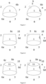
- the present invention relates to a bag suitable for being used in an upright position in an irrigation application, the bag (1) comprising:
- the bag comprises at least one gripping means (4) and/or at least one outlet (5).
- the base member (3) of the bag (1) of the present invention does not comprise an outlet and/or gripping means, preferably does not comprise any outlet and gripping means. This improves the standing capabilities of the bag (1), as no means outstand the base member (3).
- the at least one outlet (5) comprises a tamper-evidence feature.
- the tamper-evidence feature design depends on the design of the at least one outlet (5). Usually, the skilled person knows how to implement a tamper-evidence feature into an outlet.
- the distance of the at least one outlet (5) to the base member is larger than the distance of the at least one gripping means (4) to the base member.
- the at least one outlet (5) and the at least one gripping means (4) are located on opposite sides of the liquid-tight cavity (7).
- the at least one gripping means (4) is located in first part of the connection (6b) extending from the base member (3) to a point of the connection (6b) having a maximum distance to the base member (3) and wherein the at least one outlet (5) is located in a second part of the connection (6b) extending from the point of the connection (6b) having a maximum distance to the base member (3), wherein the first part and the second part of the connection (6b) are not identical.
- each of the at least two walls is a plane having four corners, preferably a rectangle. Such a design allows for improved automatic processing and even more reduce scrap material.
- the at least one outlet (5) is located in the connection (6c) between the at least two walls (2) extending between the at least two corners (10). This ensures that the distance between the at least one outlet (5) and the base member is maximized. It further ensures improved attachment of the at least one outlet (5) in the bag. Furthermore, the at least two walls (2) form together with the connection (6c) a V-shape, which acts as a funnel allowing for easy and complete removal of the irrigation solution through the at least one outlet (5). More preferably, the at least one outlet (5) is located in one of the at least two corners (10).
- the at least one outlet (5) will be held by the two connections (6d, 6c) joining in the corners allowing for even higher stability. Furthermore, the at least two walls (2) form together with each corner and connections (6d, 6c) a funnel shape, further improving the removal effect of the irrigation solution during pouring.
- the distance of the at least one gripping means (4) to the base member (3) is smaller than the distance of the at least one outlet (5) to the base member (3) resulting in an improved balance of the gravitational center of the bag during irrigation application, i.e., pouring out the irrigation solution.
- the at least one gripping means (4) is located in one connection (6d) between the at least two walls (2) extending between one of the at least two corners (9) and the at least one outlet (5) is located in the connection (6c) between the at least two walls (2) extending between a different corner of the at least two corners (10), preferably in a different corner of the at least two corners (10).
- the bag (1) further comprises a top member (11), wherein the top member is connected to the connection (6c) between the at least two walls (2) extending between the at least two corners (10), thereby forming a connection (6e) between the top member (11) and the at least two walls (2), wherein the top member (11) and the connections (6e) between the top member (11) and the at least two walls (2) form a top part (12), and wherein the connections (6e) between the top member (11) and the at least two walls (2) form a top part (12) and the connection (6d) between the at least two walls (2) extending between one of the at least two corners (10) form at least two connection joints (13).
- top member (11) allows for different attachments of the at least one outlet (5) and the at least one gripping means (4) as described in detailed further below.
- the top member (11) of the bag (1) of the present invention is configured to move at least partially into the liquid-tight cavity (7), thereby reducing the volume of the liquid-tight cavity (7).
- the top member (11) is foldable.
- the top member (11) is foldable so that the fold extends into the liquid-tight cavity (7). This allows not only a reduction of the volume of the liquid-tight cavity (7) by the fold reaching into the liquid-tight cavity (7), but also by the at least two walls moving towards each other.
- the volume of the liquid-tight cavity (7) can be significantly reduced up to a point of less than 5% of the initial volume, preferably less than 3%, and most preferably less than 1%.
- the base member could be rigid. In that case a means to facilitate folding has to be present in the base member, i.e., a hinge.
- the top member (11) comprises a flexible material, preferably a polymer material.
- the at least one outlet (5) is located in the top member (11), preferably in the connection (6e) between the top member (11) and the at least two walls (2). Most preferably, the at least one outlet (5) is located at the connection joint (13). This strengthens the above-mentioned effects, as the at least one outlet (5) will be held by the two connections (6d, 6e) joining in the corners allowing for even higher stability. Furthermore, the at least two walls (2) form together with each corner and connections (6d, 6e) a funnel shape, further improving the removal effect of the irrigation solution during pouring.
- the at least one outlet (5) is located in one of the at least two corners (10). In an alternative embodiment of the invention, the at least one outlet (5) is located in the center of the top member (11).
- the at least two corners (10) and the at least two connection joints (13) are identical.
- the breadth of the top member and the breadth of the at least one walls (2) is identical. This allows for maximizing the volume enhancement. However, it also results in removal of the at least two corners (10), which otherwise could be used to, e.g., attach the at least one outlet (5).
- the at least one gripping means (4) is located in the at least two walls (2) or in one of the connections (6d) between the at least two walls (2) extending between one of the at least two corners (9) and the connection (6a) between the base member (3) and the at least two walls (2), preferably the at least one gripping means (4) is located in one of the connections (6d) between the at least two walls (2) extending between one of the at least two corners (9) and the connection (6a) between the base member (3) and the at least two walls (2).
- the base member (3), the top member (11), and/or the at least two walls (2) are made from a liquid-tight film, preferably from a liquid-tight film having a thickness of below 300 ⁇ m, more preferably of below 250 ⁇ m, even more preferably of below 200 ⁇ m, and most preferably of below 150 ⁇ m.
- the bag Due to the flexible nature of the walls of the bag, said bag can remain partially collapsed not recovering the initial volume of the liquid-tight cavity (7) when being put aside between irrigation steps.
- semi-rigid irrigation bottles such as those manufactured by a molding technique (injection stretch blow molding, or extrusion blow molding), which are rigid, regain their original shape when no more pressure is applied by hand on the container, which tends to suck air inside the container.
- the bag according to the preferred embodiment of the present invention has the advantage that a lower amount of air is sucked in. Therefore, the risk of airborne contaminant to enter the container and eventually contaminate the irrigation solution is reduced.
- the liquid tight film comprises, preferably consists of, a polymer material.
- Polymeric material offers the best set of properties, i.e., liquid-tightness, flexibility, rigidity, printability, and easy processability.
- Preferable polymer materials for the present invention are selected from the list consisting of polyethylene, polypropylene, polyethylene terephthalate, polyamide, ethylene vinyl alcohol, or mixtures thereof.
- the polymer material of the present invention is selected from polyethylene or polypropylene.
- the polymer material of the bag of the present invention has a haze value measured according to ASTM D1003, Procedure B, of less than 60%, preferably less than 30%, more preferably less than 25%, and most preferably less than 15%.
- a scale is printed on at least one of the at least two walls (2) allowing for a more accurate determination of the filling state of the bag of the present invention.
- the bag of the present invention is at least partially filled with an irrigation solution.
- the bag of the present invention filled with an irrigation solution comprises the irrigation solution and a headspace filled with gas, wherein the gas could be air but also other gases such as inert gases, i.e., nitrogen or noble gases.
- the volume of the headspace is smaller than the volume of the liquid filled part of the liquid-tight cavity (7). More preferably, the volume of the headspace is less than 10% of the total volume of the liquid cavity (7), preferably less than 5%, more preferably less than 2%, and most preferably less than 1%.
- the volume of the headspace can be controlled by either adding further gas through the inlet (increasing the volume) or by removal of the gas (decreasing the volume).
- the removal of the gas can be preferably carried out by mechanical pressing on the bag or by vacuuming the bag in a position to allow the gas from the headspace to leave the bag during the treatment.
- the present invention further provides a use of the bag according to any of the embodiments described above in an irrigation application.
- the bag is filled with an irrigation solution and is subjected to a sterilization process.
- the bag is opened by hand and the irrigation solution is poured on the surgery field or object to be irrigated.
- the invention further relates to a process for irrigating an object during surgery, providing the following steps:
- the present invention is concerned with a process for producing a bag according to any of the embodiments described above, the process comprising the steps of:
- the film is a liquid-tight film, preferably a liquid-tight film having a thickness of below 250 ⁇ m, more preferably of below 200 ⁇ m, and most preferably of below 150 ⁇ m.
- the thickness of the film is not lower than 60 ⁇ m.
- the liquid-tight film comprises, preferably consists of, a polymer material.
- a polymer material Preferable polymer materials for the present invention are selected from the list consisting of polyethylene, polypropylene, polyethylene terephthalate, polyamide, ethylene vinyl alcohol, or mixtures thereof.
- the polymer material of the present invention is selected from polyethylene or polypropylene.
- the polymer material of the bag of the present invention has a haze value measured according to ASTM D1003, Procedure B, of less than 60%, preferably less than 30%, more preferably less than 25%, and most preferably less than 15%.
- the process further comprises the step of filling the bag with an irrigation solution, preferably via the at least one inlet (14), and sealing the bag or closing the inlet.
- the bag can be filled via the at least one outlet (5) and sealed or closed afterwards. After closing the at least one outlet (5) and/or at least one inlet (14), if present in the bag, and sealing the bag, the bag and the irrigation solution have to be sterilized to be used in an irrigation application.
- the process further comprises the step of subjecting the bag and the irrigation solution to a sterilization step.
- the amount of gas included in the bag is as low as possible.
- the filling and sealing steps are performed while maintaining a vacuum.
- the process comprises the step of squeezing the bag before sealing it, to achieve that the gas is pushed out of the bag before sealing.
Landscapes
- Health & Medical Sciences (AREA)
- Veterinary Medicine (AREA)
- Life Sciences & Earth Sciences (AREA)
- Animal Behavior & Ethology (AREA)
- General Health & Medical Sciences (AREA)
- Public Health (AREA)
- Pharmacology & Pharmacy (AREA)
- Hematology (AREA)
- Engineering & Computer Science (AREA)
- Anesthesiology (AREA)
- Biomedical Technology (AREA)
- Heart & Thoracic Surgery (AREA)
- Bag Frames (AREA)
Priority Applications (2)
| Application Number | Priority Date | Filing Date | Title |
|---|---|---|---|
| EP23193252.6A EP4512737A1 (de) | 2023-08-24 | 2023-08-24 | Standbeutel für bewässerungsanwendung |
| PCT/IB2024/058169 WO2025041071A1 (en) | 2023-08-24 | 2024-08-22 | Standing bag for irrigation application |
Applications Claiming Priority (1)
| Application Number | Priority Date | Filing Date | Title |
|---|---|---|---|
| EP23193252.6A EP4512737A1 (de) | 2023-08-24 | 2023-08-24 | Standbeutel für bewässerungsanwendung |
Publications (1)
| Publication Number | Publication Date |
|---|---|
| EP4512737A1 true EP4512737A1 (de) | 2025-02-26 |
Family
ID=87801072
Family Applications (1)
| Application Number | Title | Priority Date | Filing Date |
|---|---|---|---|
| EP23193252.6A Withdrawn EP4512737A1 (de) | 2023-08-24 | 2023-08-24 | Standbeutel für bewässerungsanwendung |
Country Status (2)
| Country | Link |
|---|---|
| EP (1) | EP4512737A1 (de) |
| WO (1) | WO2025041071A1 (de) |
Citations (9)
| Publication number | Priority date | Publication date | Assignee | Title |
|---|---|---|---|---|
| US3641999A (en) * | 1970-04-06 | 1972-02-15 | Ezem Co | Standup container adapted for the administration of enemas |
| GB1287668A (en) | 1970-02-18 | 1972-09-06 | Elliot Lab Inc | Bag for administering medical fluids |
| US6076967A (en) * | 1997-06-05 | 2000-06-20 | Beaudette; Susan A. | Fillable disposable drink bag |
| EP1946785A1 (de) * | 2007-01-19 | 2008-07-23 | Coloplast A/S | Bewässerungssystem |
| WO2010137338A1 (ja) | 2009-05-29 | 2010-12-02 | 株式会社細川洋行 | 医療用容器、医療用容器の製造方法、及び輸液入り医療用容器の製造方法 |
| EP2767270A1 (de) | 2011-10-11 | 2014-08-20 | Ajinomoto Co., Inc. | Infusionsbehälter mit standbeutel |
| US20150122842A1 (en) * | 2013-11-06 | 2015-05-07 | The Procter & Gamble Company | Containers having a product volume and a stand-off structure coupled thereto |
| US20170290740A1 (en) * | 2015-02-27 | 2017-10-12 | Gavis Pharmaceuticals | Colonoscopy prep bag and methods of use |
| US20200206411A1 (en) * | 2017-08-24 | 2020-07-02 | Hollister Incorporated | Hollow Organ Irrigation Systems |
-
2023
- 2023-08-24 EP EP23193252.6A patent/EP4512737A1/de not_active Withdrawn
-
2024
- 2024-08-22 WO PCT/IB2024/058169 patent/WO2025041071A1/en active Pending
Patent Citations (9)
| Publication number | Priority date | Publication date | Assignee | Title |
|---|---|---|---|---|
| GB1287668A (en) | 1970-02-18 | 1972-09-06 | Elliot Lab Inc | Bag for administering medical fluids |
| US3641999A (en) * | 1970-04-06 | 1972-02-15 | Ezem Co | Standup container adapted for the administration of enemas |
| US6076967A (en) * | 1997-06-05 | 2000-06-20 | Beaudette; Susan A. | Fillable disposable drink bag |
| EP1946785A1 (de) * | 2007-01-19 | 2008-07-23 | Coloplast A/S | Bewässerungssystem |
| WO2010137338A1 (ja) | 2009-05-29 | 2010-12-02 | 株式会社細川洋行 | 医療用容器、医療用容器の製造方法、及び輸液入り医療用容器の製造方法 |
| EP2767270A1 (de) | 2011-10-11 | 2014-08-20 | Ajinomoto Co., Inc. | Infusionsbehälter mit standbeutel |
| US20150122842A1 (en) * | 2013-11-06 | 2015-05-07 | The Procter & Gamble Company | Containers having a product volume and a stand-off structure coupled thereto |
| US20170290740A1 (en) * | 2015-02-27 | 2017-10-12 | Gavis Pharmaceuticals | Colonoscopy prep bag and methods of use |
| US20200206411A1 (en) * | 2017-08-24 | 2020-07-02 | Hollister Incorporated | Hollow Organ Irrigation Systems |
Also Published As
| Publication number | Publication date |
|---|---|
| WO2025041071A1 (en) | 2025-02-27 |
Similar Documents
| Publication | Publication Date | Title |
|---|---|---|
| CN1116860C (zh) | 储存肠胃外流体的改进容器 | |
| EP1031340B1 (de) | Mittel um die Form eines flexiblen medizinischen Behälters zu halten | |
| JPS58146348A (ja) | 単位投与量注射液容器 | |
| US20250114274A1 (en) | Food arrangement | |
| CN102007046A (zh) | 用于食品、尤其是滴剂的包装 | |
| US5984912A (en) | Collapsible medical bag for the containment and delivery of diagnostic contrast media and parenteral drug formulations | |
| JP2023553308A (ja) | マルチ滅菌チャンバパック | |
| JP2002500917A (ja) | 二重パッケージ | |
| EP4512737A1 (de) | Standbeutel für bewässerungsanwendung | |
| WO2025041073A1 (en) | Recyclable plastic container comprising a label | |
| JP2010273934A (ja) | 医療用容器、医療用容器の製造方法、及び輸液入り医療用容器の製造方法 | |
| CN221059866U (zh) | 一种消毒刷 | |
| US20250276124A1 (en) | Container for irrigation application producible on a production line for producing infusion containers | |
| JPH09240629A (ja) | 無菌充填装置における紙容器の殺菌方法及び殺菌装置 | |
| US20250275889A1 (en) | Container for irrigation application comprising a precisely defined opening and a production process thereof | |
| EP4512732A1 (de) | Recycelbarer kunststoffbehälter mit einem etikett | |
| US20250276483A1 (en) | Process and system for producing containers for irrigation application on a production line for producing infusion containers | |
| CN212333407U (zh) | 一种带消毒液的口罩气泡袋 | |
| JP4383561B2 (ja) | 薬剤混合輸液バッグ | |
| JP2017186079A (ja) | チャック付き包装袋 | |
| CN204734721U (zh) | 负压式多层聚丙烯输液袋 | |
| CN218685696U (zh) | 一种一次性使用皮肤消毒装置 | |
| JP2004097743A (ja) | 薬液収容容器 | |
| JPH07231927A (ja) | 薬液用ブローバッグ | |
| CN209864811U (zh) | 一种更换腹透短管包 |
Legal Events
| Date | Code | Title | Description |
|---|---|---|---|
| PUAI | Public reference made under article 153(3) epc to a published international application that has entered the european phase |
Free format text: ORIGINAL CODE: 0009012 |
|
| STAA | Information on the status of an ep patent application or granted ep patent |
Free format text: STATUS: THE APPLICATION HAS BEEN PUBLISHED |
|
| AK | Designated contracting states |
Kind code of ref document: A1 Designated state(s): AL AT BE BG CH CY CZ DE DK EE ES FI FR GB GR HR HU IE IS IT LI LT LU LV MC ME MK MT NL NO PL PT RO RS SE SI SK SM TR |
|
| STAA | Information on the status of an ep patent application or granted ep patent |
Free format text: STATUS: THE APPLICATION IS DEEMED TO BE WITHDRAWN |
|
| 18D | Application deemed to be withdrawn |
Effective date: 20250827 |