EP4512734A2 - Verfahren zum herstellen eines behälters mit einer lecksicheren dichtung - Google Patents
Verfahren zum herstellen eines behälters mit einer lecksicheren dichtung Download PDFInfo
- Publication number
- EP4512734A2 EP4512734A2 EP24222854.2A EP24222854A EP4512734A2 EP 4512734 A2 EP4512734 A2 EP 4512734A2 EP 24222854 A EP24222854 A EP 24222854A EP 4512734 A2 EP4512734 A2 EP 4512734A2
- Authority
- EP
- European Patent Office
- Prior art keywords
- container
- seal
- leak resistant
- seal portion
- resistant seal
- Prior art date
- Legal status (The legal status is an assumption and is not a legal conclusion. Google has not performed a legal analysis and makes no representation as to the accuracy of the status listed.)
- Pending
Links
Images


Classifications
-
- B—PERFORMING OPERATIONS; TRANSPORTING
- B29—WORKING OF PLASTICS; WORKING OF SUBSTANCES IN A PLASTIC STATE IN GENERAL
- B29C—SHAPING OR JOINING OF PLASTICS; SHAPING OF MATERIAL IN A PLASTIC STATE, NOT OTHERWISE PROVIDED FOR; AFTER-TREATMENT OF THE SHAPED PRODUCTS, e.g. REPAIRING
- B29C45/00—Injection moulding, i.e. forcing the required volume of moulding material through a nozzle into a closed mould; Apparatus therefor
- B29C45/14—Injection moulding, i.e. forcing the required volume of moulding material through a nozzle into a closed mould; Apparatus therefor incorporating preformed parts or layers, e.g. injection moulding around inserts or for coating articles
-
- B—PERFORMING OPERATIONS; TRANSPORTING
- B29—WORKING OF PLASTICS; WORKING OF SUBSTANCES IN A PLASTIC STATE IN GENERAL
- B29C—SHAPING OR JOINING OF PLASTICS; SHAPING OF MATERIAL IN A PLASTIC STATE, NOT OTHERWISE PROVIDED FOR; AFTER-TREATMENT OF THE SHAPED PRODUCTS, e.g. REPAIRING
- B29C43/00—Compression moulding, i.e. applying external pressure to flow the moulding material; Apparatus therefor
- B29C43/02—Compression moulding, i.e. applying external pressure to flow the moulding material; Apparatus therefor of articles of definite length, i.e. discrete articles
- B29C43/14—Compression moulding, i.e. applying external pressure to flow the moulding material; Apparatus therefor of articles of definite length, i.e. discrete articles in several steps
-
- B—PERFORMING OPERATIONS; TRANSPORTING
- B29—WORKING OF PLASTICS; WORKING OF SUBSTANCES IN A PLASTIC STATE IN GENERAL
- B29C—SHAPING OR JOINING OF PLASTICS; SHAPING OF MATERIAL IN A PLASTIC STATE, NOT OTHERWISE PROVIDED FOR; AFTER-TREATMENT OF THE SHAPED PRODUCTS, e.g. REPAIRING
- B29C43/00—Compression moulding, i.e. applying external pressure to flow the moulding material; Apparatus therefor
- B29C43/02—Compression moulding, i.e. applying external pressure to flow the moulding material; Apparatus therefor of articles of definite length, i.e. discrete articles
- B29C43/18—Compression moulding, i.e. applying external pressure to flow the moulding material; Apparatus therefor of articles of definite length, i.e. discrete articles incorporating preformed parts or layers, e.g. compression moulding around inserts or for coating articles
-
- B—PERFORMING OPERATIONS; TRANSPORTING
- B29—WORKING OF PLASTICS; WORKING OF SUBSTANCES IN A PLASTIC STATE IN GENERAL
- B29C—SHAPING OR JOINING OF PLASTICS; SHAPING OF MATERIAL IN A PLASTIC STATE, NOT OTHERWISE PROVIDED FOR; AFTER-TREATMENT OF THE SHAPED PRODUCTS, e.g. REPAIRING
- B29C45/00—Injection moulding, i.e. forcing the required volume of moulding material through a nozzle into a closed mould; Apparatus therefor
- B29C45/0053—Injection moulding, i.e. forcing the required volume of moulding material through a nozzle into a closed mould; Apparatus therefor combined with a final operation, e.g. shaping
- B29C45/0055—Shaping
-
- B—PERFORMING OPERATIONS; TRANSPORTING
- B29—WORKING OF PLASTICS; WORKING OF SUBSTANCES IN A PLASTIC STATE IN GENERAL
- B29C—SHAPING OR JOINING OF PLASTICS; SHAPING OF MATERIAL IN A PLASTIC STATE, NOT OTHERWISE PROVIDED FOR; AFTER-TREATMENT OF THE SHAPED PRODUCTS, e.g. REPAIRING
- B29C45/00—Injection moulding, i.e. forcing the required volume of moulding material through a nozzle into a closed mould; Apparatus therefor
- B29C45/02—Transfer moulding, i.e. transferring the required volume of moulding material by a plunger from a "shot" cavity into a mould cavity
-
- B—PERFORMING OPERATIONS; TRANSPORTING
- B29—WORKING OF PLASTICS; WORKING OF SUBSTANCES IN A PLASTIC STATE IN GENERAL
- B29C—SHAPING OR JOINING OF PLASTICS; SHAPING OF MATERIAL IN A PLASTIC STATE, NOT OTHERWISE PROVIDED FOR; AFTER-TREATMENT OF THE SHAPED PRODUCTS, e.g. REPAIRING
- B29C45/00—Injection moulding, i.e. forcing the required volume of moulding material through a nozzle into a closed mould; Apparatus therefor
- B29C45/14—Injection moulding, i.e. forcing the required volume of moulding material through a nozzle into a closed mould; Apparatus therefor incorporating preformed parts or layers, e.g. injection moulding around inserts or for coating articles
- B29C45/14336—Coating a portion of the article, e.g. the edge of the article
-
- B—PERFORMING OPERATIONS; TRANSPORTING
- B29—WORKING OF PLASTICS; WORKING OF SUBSTANCES IN A PLASTIC STATE IN GENERAL
- B29C—SHAPING OR JOINING OF PLASTICS; SHAPING OF MATERIAL IN A PLASTIC STATE, NOT OTHERWISE PROVIDED FOR; AFTER-TREATMENT OF THE SHAPED PRODUCTS, e.g. REPAIRING
- B29C45/00—Injection moulding, i.e. forcing the required volume of moulding material through a nozzle into a closed mould; Apparatus therefor
- B29C45/14—Injection moulding, i.e. forcing the required volume of moulding material through a nozzle into a closed mould; Apparatus therefor incorporating preformed parts or layers, e.g. injection moulding around inserts or for coating articles
- B29C45/14467—Joining articles or parts of a single article
- B29C45/14475—Joining juxtaposed parts of a single article, e.g. edges of a folded container blank
-
- B—PERFORMING OPERATIONS; TRANSPORTING
- B65—CONVEYING; PACKING; STORING; HANDLING THIN OR FILAMENTARY MATERIAL
- B65D—CONTAINERS FOR STORAGE OR TRANSPORT OF ARTICLES OR MATERIALS, e.g. BAGS, BARRELS, BOTTLES, BOXES, CANS, CARTONS, CRATES, DRUMS, JARS, TANKS, HOPPERS, FORWARDING CONTAINERS; ACCESSORIES, CLOSURES, OR FITTINGS THEREFOR; PACKAGING ELEMENTS; PACKAGES
- B65D33/00—Details of, or accessories for, sacks or bags
- B65D33/02—Local reinforcements or stiffening inserts, e.g. wires, strings, strips or frames
-
- B—PERFORMING OPERATIONS; TRANSPORTING
- B65—CONVEYING; PACKING; STORING; HANDLING THIN OR FILAMENTARY MATERIAL
- B65D—CONTAINERS FOR STORAGE OR TRANSPORT OF ARTICLES OR MATERIALS, e.g. BAGS, BARRELS, BOTTLES, BOXES, CANS, CARTONS, CRATES, DRUMS, JARS, TANKS, HOPPERS, FORWARDING CONTAINERS; ACCESSORIES, CLOSURES, OR FITTINGS THEREFOR; PACKAGING ELEMENTS; PACKAGES
- B65D33/00—Details of, or accessories for, sacks or bags
- B65D33/16—End- or aperture-closing arrangements or devices
- B65D33/24—End- or aperture-closing arrangements or devices using self-locking integral or attached closure elements, e.g. flaps
- B65D33/243—Combination of flaps, slits, tongues or apertures, e.g. apertures serving as hand or finger holes
-
- B—PERFORMING OPERATIONS; TRANSPORTING
- B65—CONVEYING; PACKING; STORING; HANDLING THIN OR FILAMENTARY MATERIAL
- B65D—CONTAINERS FOR STORAGE OR TRANSPORT OF ARTICLES OR MATERIALS, e.g. BAGS, BARRELS, BOTTLES, BOXES, CANS, CARTONS, CRATES, DRUMS, JARS, TANKS, HOPPERS, FORWARDING CONTAINERS; ACCESSORIES, CLOSURES, OR FITTINGS THEREFOR; PACKAGING ELEMENTS; PACKAGES
- B65D33/00—Details of, or accessories for, sacks or bags
- B65D33/16—End- or aperture-closing arrangements or devices
- B65D33/25—Riveting; Dovetailing; Screwing; using press buttons or slide fasteners
- B65D33/2508—Riveting; Dovetailing; Screwing; using press buttons or slide fasteners using slide fasteners with interlocking members having a substantially uniform section throughout the length of the fastener; Sliders therefor
- B65D33/2541—Riveting; Dovetailing; Screwing; using press buttons or slide fasteners using slide fasteners with interlocking members having a substantially uniform section throughout the length of the fastener; Sliders therefor characterised by the slide fastener, e.g. adapted to interlock with a sheet between the interlocking members having sections of particular shape
-
- B—PERFORMING OPERATIONS; TRANSPORTING
- B65—CONVEYING; PACKING; STORING; HANDLING THIN OR FILAMENTARY MATERIAL
- B65D—CONTAINERS FOR STORAGE OR TRANSPORT OF ARTICLES OR MATERIALS, e.g. BAGS, BARRELS, BOTTLES, BOXES, CANS, CARTONS, CRATES, DRUMS, JARS, TANKS, HOPPERS, FORWARDING CONTAINERS; ACCESSORIES, CLOSURES, OR FITTINGS THEREFOR; PACKAGING ELEMENTS; PACKAGES
- B65D53/00—Sealing or packing elements; Sealings formed by liquid or plastics material
- B65D53/06—Sealings formed by liquid or plastic material
-
- B—PERFORMING OPERATIONS; TRANSPORTING
- B65—CONVEYING; PACKING; STORING; HANDLING THIN OR FILAMENTARY MATERIAL
- B65D—CONTAINERS FOR STORAGE OR TRANSPORT OF ARTICLES OR MATERIALS, e.g. BAGS, BARRELS, BOTTLES, BOXES, CANS, CARTONS, CRATES, DRUMS, JARS, TANKS, HOPPERS, FORWARDING CONTAINERS; ACCESSORIES, CLOSURES, OR FITTINGS THEREFOR; PACKAGING ELEMENTS; PACKAGES
- B65D81/00—Containers, packaging elements, or packages, for contents presenting particular transport or storage problems, or adapted to be used for non-packaging purposes after removal of contents
- B65D81/34—Containers, packaging elements, or packages, for contents presenting particular transport or storage problems, or adapted to be used for non-packaging purposes after removal of contents for packaging foodstuffs or other articles intended to be cooked or heated within the package
- B65D81/3446—Containers, packaging elements, or packages, for contents presenting particular transport or storage problems, or adapted to be used for non-packaging purposes after removal of contents for packaging foodstuffs or other articles intended to be cooked or heated within the package specially adapted to be heated by microwaves
- B65D81/3461—Flexible containers, e.g. bags, pouches, envelopes
-
- B—PERFORMING OPERATIONS; TRANSPORTING
- B29—WORKING OF PLASTICS; WORKING OF SUBSTANCES IN A PLASTIC STATE IN GENERAL
- B29C—SHAPING OR JOINING OF PLASTICS; SHAPING OF MATERIAL IN A PLASTIC STATE, NOT OTHERWISE PROVIDED FOR; AFTER-TREATMENT OF THE SHAPED PRODUCTS, e.g. REPAIRING
- B29C45/00—Injection moulding, i.e. forcing the required volume of moulding material through a nozzle into a closed mould; Apparatus therefor
- B29C45/14—Injection moulding, i.e. forcing the required volume of moulding material through a nozzle into a closed mould; Apparatus therefor incorporating preformed parts or layers, e.g. injection moulding around inserts or for coating articles
- B29C45/14336—Coating a portion of the article, e.g. the edge of the article
- B29C2045/14459—Coating a portion of the article, e.g. the edge of the article injecting seal elements
-
- B—PERFORMING OPERATIONS; TRANSPORTING
- B29—WORKING OF PLASTICS; WORKING OF SUBSTANCES IN A PLASTIC STATE IN GENERAL
- B29L—INDEXING SCHEME ASSOCIATED WITH SUBCLASS B29C, RELATING TO PARTICULAR ARTICLES
- B29L2031/00—Other particular articles
- B29L2031/712—Containers; Packaging elements or accessories, Packages
-
- B—PERFORMING OPERATIONS; TRANSPORTING
- B65—CONVEYING; PACKING; STORING; HANDLING THIN OR FILAMENTARY MATERIAL
- B65D—CONTAINERS FOR STORAGE OR TRANSPORT OF ARTICLES OR MATERIALS, e.g. BAGS, BARRELS, BOTTLES, BOXES, CANS, CARTONS, CRATES, DRUMS, JARS, TANKS, HOPPERS, FORWARDING CONTAINERS; ACCESSORIES, CLOSURES, OR FITTINGS THEREFOR; PACKAGING ELEMENTS; PACKAGES
- B65D53/00—Sealing or packing elements; Sealings formed by liquid or plastics material
Definitions
- Embodiments of the invention generally relate to the field of manufacturing of storage and transport bags and containers and seals for these bags and containers. More particularly, but not by way of limitation, one or more embodiments relate to an inside out method of manufacturing a container with a leak resistant seal that includes forming an elastomer or a plastic or any combination thereof into a container inside out to facilitate manufacturing, for example using less steps and to provide a seal with enhanced leak resistance, for example that can maintain a seal that resists leakage of liquids and solids from the container during storage and transport without the aid of an external structure to maintain the seal.
- Sealable bags and containers have been made for many years but are difficult to manufacture when using seals that must engage to remain closed. For example, manufacturing sealable plastic bags generally requires extruded parts, including seals that may be part of the container or later bonded to the container wherein the containers are cut with hot knives to create sealed edges.
- Plastic bags are generally created for single use and have chemicals that are undesirable for food storage for example. The resulting number of plastic bags thrown away on an annual basis is very high.
- Elastomeric bags, which have been made for reuse have generally been molded, for example with compression molding or liquid injection molding. The resulting elastomeric bags are highly elastic compared to plastic bags and their seals are generally bonded or molded into the inner portion of the bag.
- Elastomeric sealable bags are more durable than their plastic throwaway counterparts and a single reusable bag can save hundreds if not thousands of plastic bags.
- both Munguia in US Patent Publication 2013/0105352 and LeBoeuf in US Patent Publication 2009/0110335 teach silicone food storage bags with seals.
- the problems with both of these devices is that they require external clamps or other external structures to seal the bags because their seals are not strong enough to be leak resistant.
- Svec, U.S. Patent 2,780,261 shows one embodiment that can hold liquid inside of it, namely as shown and described with respect to Figure 7 .
- a limitation of the existing sealable bags is that the integrated seal designs provide relatively weak sealing force based on the elastic nature of elastomers.
- Plastic bags provide a weak sealing force, but for a different reason, mainly because the seals are extremely small, with ridges that are approximately 10 times thinner than a human fingernail, 0.1 mm.
- Ziploc ® bags are closeable, but they are not leak proof. This lack of leak resistance is a consequence of the relatively small sealing area and the simple track and groove shapes of the Ziploc ® seal.
- the rigidity of the seal when made this small has to be outside of the Shore A scale and well into the Shore D scale, i.e., 45-85 Shore D, typically in the 45-60 Shore D range and usually above 50 Shore D.
- extrusion imperfections when making the seals with this rigidity yield slight variations in the thickness of the seal and this provides a lower yield of containers that have acceptable leak resistance.
- Attempts to make the seals strong require use of sliders to open and close the bags, i.e., to allow children or elderly or weak individuals to open and close the bags. Sliders generally provide an opening on the end of the slider that leaks.
- Silverman U.S. Patent No. 2,674,289 teaches a rubber container, namely a tobacco pouch that is molded inside out. This eliminates the step of bonding a seal to the container and simplifies the mold since the container can be inverted after molding.
- Silverman's seal tapers at the ends and when inverted for use, results in a complete lack of sealing force at the ends since the seal tapering produces no contact for ridges and indentations at the ends of the seal i.e., no seal at the ends.
- Silverman's design thus requires rivets, leather jacketing and a separate zipper e.g., external structures, to hold the seal together. Silverman also requires extra manufacturing steps of riveting the ends of the seal, etc., and is not leak resistant unless the external structure, e.g., rivets, are utilized.
- Embodiments of the invention generally relate to an inside out method of manufacturing a container with a leak resistant seal that includes forming an elastomer or a plastic or any combination thereof into a container inside out.
- the method includes forming an outside portion of the container on an internal surface of the container before inverting the container and forming an inside portion of the container on an external surface of the container before inverting the container.
- the method includes forming or coupling a leak resistant seal on the external surface of the container before inverting the container.
- the leak resistant seal provides access to the inside portion of the container when the leak resistant seal is open after inverting the container and holds at least liquid internal to the container when applying an external force to the container without use of an external structure to keep the leak resistant seal closed after inverting the container.
- One or more embodiments includes inverting the external surface of the container and the leak resistant seal with the internal surface of the container such that the inside portion of the container and the leak resistant seal are located within the container and the outside portion of the container is located outside of the container.
- forming the inside portion of the container on the external surface of the container includes forming a gap on the external surface between a first side of the leak resistant seal and a second side of the leak resistant seal that engage each other after inverting the container.
- the gap provides an abutment that each end of the first side and second side of the leak resistant seal contact to keep the leak resistant seal from leaking when the applying the external force to the container occurs.
- the gap is less than or equal to a thickness of the leak resistant seal.
- forming or coupling the leak resistant seal includes utilizing a leak resistant seal with a first seal portion and a second seal portion that couple with each other along a boundary to seal the container and decouple from each other along the boundary to open the container.
- the first seal portion and the second seal portion are at least 1 mm thick, or at least 2 mm thick, or at least 3 mm thick, or greater than 3 mm thick.
- This metric for the winding path may yield ratios of at least 4, 5, 6, 7, 8, 9, or greater than 10.
- the seal may have gaps within it to enable the seal to open more easily.
- the gaps may be symmetrical on each side of any protrusion or cavity for example or may be asymmetrical. By including a gap on one side of the protrusion, the seal may be opened more easily from the side having the gap for example.
- the first seal portion and the second seal portion include at least one corresponding protrusion or indentation that includes a geometric shape that is wider than another portion of the at least one corresponding protrusion or indentation.
- the seal may also include gaps meaning that the shapes of ridges and recesses that correspond to one another, i.e., that fit into one another, whether in full contact across the entire boundary or not, may be of different shapes.
- utilizing the leak resistant seal includes utilizing the protrusion or the indentation having a height of at least 2 mm and utilizing the geometric shape having a width of at least 1 mm thicker than the protrusion or the indentation.
- utilizing the leak resistant seal includes utilizing the protrusion or the indentation having a height of at least 2 mm and utilizing the geometric shape having a width of at least 2 mm thicker than the protrusion or the indentation.
- At least one embodiment of the invention includes forming the container with a width near the leak resistant seal that is larger than an opposing width of the container away from the leak resistant seal.
- the leak resistant seal includes a first side and a second side that engage each other.
- the first side includes a different average thickness than the second side.
- the first side is made from a different material than the second side.
- the first side includes a different hardness value than the second side.
- the leak resistant seal is made from a different material than a remaining portion of the container that does not include the leak resistant seal.
- the leak resistant seal includes a different hardness value than the remaining portion of the container that does not include the leak resistant seal.
- One or more embodiments of the invention include forming the elastomer into the container with a hardness of between 70 and 80 on a Shore A durometer scale. At least one embodiment of the invention includes forming the elastomer into the container with a hardness of between 40 and 90, or at least less than or equal to 100 on a Shore A durometer scale.
- One or more embodiments include utilizing an uncured, heat curable elastomer, wherein forming the elastomer into the container includes heat curing the container.
- coupling the leak resistant seal includes gluing, bonding or attaching the leak resistant seal to the container to couple the leak resistant seal by co-molding the container and the leak resistant seal together or by over-molding the container to the leak resistant seal or by over-molding the leak resistant seal to the container.
- At least one embodiment of the invention includes forming the leak resistant seal without bonding or gluing opposing sides of the leak resistant seal at opposing ends of the leak resistant seal, i.e., so that there is a gap between one side of the seal and the other at the ends, wherein when inverted inside out, the two seal portions eliminate the gap to provide a leak resistant seal.
- One or more embodiments of the invention include forming a bottom on the container such that the container may stand upright.
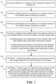
- Figure 1 illustrates an exemplary flowchart of the inside out method of manufacturing a container with a leak resistant seal
- Figure 2 shows a perspective view of the container after manufacture and before the container is inverted, i.e., before being configured for use as a container with a leak resistant seal, according to one or more embodiments of the invention.
- Embodiments of the invention generally relate to a method of manufacturing a container 200 with a leak resistant seal 203 that includes 101 forming an elastomer or a plastic, or thermoplastic elastomers, which are plastics that can behave in some ways like elastomers depending on their specific characteristics, or any combination thereof into a container 200, for example inside out.
- the leak resistant seal 203 providing access to the inside portion 202 of the container 200 when the leak resistant seal 203 is open after inverting the container 200, and when the container is sealed holding at least liquid, and/or another substance, internal to the container 200 when applying an external force to the container 200 without use of an external structure to keep the leak resistant seal 203 closed after inverting the container 200.
- Part of the manufacturing process may optionally include inverting the external surface of the container and the leak resistant seal with the internal surface of the container at 105.
- the container may be delivered inside out where the end user or customer inverts the container.
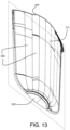
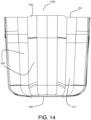
- Figure 13 shows a cross-section view, specifically an upper perspective cross-section view, of the internal surface of the container before being inverted and Figure 14 shows a front view of the container after being inverted, according to one or more embodiments of the invention.
- the container 200 may include a tab 440 and flutes 350 on the internal surface 211, i.e., that becomes the outside portion 201 of the container after the container is inverted.
- one or more embodiments of the invention includes inverting the external surface 212 of the container 200 and the leak resistant seal 203 (not shown in Figure 14 ) with the internal surface 211 of the container 200 such that the inside portion 202 of the container and the leak resistant seal 203 are located within the container 200 and the outside portion 201 of the container is located outside of the container 200, to form a container 1400 ready for use.
- the tabs 440 and the flutes 350 are shown on the outside portion 201.
- the container as a whole has two enclosure parts that define an inner volume, whether merely a designation of a single container when formed simultaneously, i.e., coupled to one another during molding, or whether formed separately and then coupled to one another, i.e., via bonding.
- the parts may be formed as shown in Figs. 13 and 14 or in any other manner, e.g., could be made in at least two parts across the cross-section plan shown in Fig. 3 , with a mirror image part on the other side of the plane that are then bonded for example.
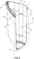
- Figure 3 shows a cross-section view of a left side of the container before the container is inverted, according to one or more embodiments of the invention.
- the container 200 includes the leak resistant seal 203 with a first side 204 and a second side 205.
- One or more embodiments of the invention include forming a bottom 330, such as a rim or feet, on the container 200 such that the container 200 may stand upright.
- the bottom 330 protrudes or faces outward away from the container 200, and after being inverted the bottom 330 protrudes or faces inward towards and into the container 200.
- the edges of the leak resistant seal 203 on both edges of the container 200 protrude or face outward away from the container 200, and after being inverted, the edges of the leak resistant seal 203 protrude or face inward towards each other in an inner portion of the container 200.
- the flutes 350 of the container 200 may end at a predetermined distance from a top edge of the container 200, wherein the top edge is opposite that of the bottom 330.
- the predetermined distance may be 15 mm, less than 15 mm or more than 15 mm.
- the flutes 350 end at the predetermined distance from the top edge of the container 200 in order to avoid interference when inverting the container 200 along the edge to make the seal with the leak resistant seal 203.
- the leak resistant seal 203 includes a first side 204 and a second side 205 that engage each other.
- the first side 204 may include a different average thickness than the second side 205.
- the first side 204 may be made from a different material than the second side 205.
- the first side 204 may include a different hardness value than the second side 205.
- the leak resistant seal 203 may be made from a different material than a remaining portion of the container 200 that does not include the leak resistant seal 203.
- the leak resistant seal 203 may include a different hardness value than the remaining portion of the container 200 that does not include the leak resistant seal 203.
- One or more embodiments of the invention include forming the elastomer into the container 200 with a hardness of between 70 and 80 on a Shore A durometer scale. At least one embodiment of the invention includes forming the elastomer into the container 200 with a hardness of between 40 and 90 on a Shore A durometer scale, or in any case less than 100 Shore A.
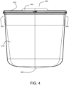
- Figure 4 shows a front view of the container before being inverted, according to one or more embodiments of the invention and Figure 5 shows a back view of the container before being inverted, according to one or more embodiments of the invention.
- At least one embodiment of the invention includes forming the container 200 with a width near the leak resistant seal 203 that is larger than an opposing width of the container 200 away from the leak resistant seal 203.
- the container 200 may include a tab 440, wherein the tab 440 may include a tab side on each side of the container 200 and each side of the leak resistant seal 203.
- forming the container 200 includes forming the leak resistant seal 203 at opposing edges 550, 560 of the container 200 that are at least as thick as the leak resistant seal 203 between the opposing edges 550 560.
- forming the elastomer into the container 200 includes liquid injection molding, plastic injection molding or compression molding.
- One or more embodiments may include forming the container by utilizing thermoplastic elastomers wherein forming the container includes melting the elastomer and injection molding the material.
- At least one embodiment of the invention includes forming the container 200 in one molding step without attaching any material to the container 200 after the molding. This provides an extremely rapid method of manufacturing a leak resistant seal for storage and transport that does not require external structures or clips to hold the seal together.
- coupling the leak resistant seal 203 includes one or more of gluing, bonding and attaching the leak resistant seal 203 to the container 200 to couple the leak resistant seal 203 by co-molding the container 200 and the leak resistant seal 203 together or by over-molding the container 200 to the leak resistant seal 203 or by over-molding the leak resistant seal 203 to the container 200.
- This enables different types of materials to be utilized in the manufacturing of the container but requires more steps than the one step method described herein.
- each end of the first side 204 and second side 205 may include a gap seal, or one end of one of the first side 204 and the second side 205 may include a gap seal, or the gap 206 may include a gap seal, or any combination thereof.
- forming or coupling the leak resistant seal 203 includes utilizing a leak resistant seal 203 with a first seal portion 620 and a second seal portion 621 that couple with each other along a boundary to seal the container 200 and decouple from each other along the boundary to open the container 200.
- the boundary is a line that defines an area between the first seal portion 620 and the second seal portion 621 that allows the first seal portion 620 to contact or to mate or couple or engage with the second seal portion 621.
- the boundary defines a path of contact or coupling or mating or engagement between the first seal portion 620 and the second seal portion 621 that is at least 2 times a horizontal distance between a start of the path and an end of the path.
- the path is at least 2.5 times the horizontal distance between the start of the path and the end of the path, or at least 3 times the horizontal distance between the start of the path and the end of the path, or at least 5 times the horizontal distance between the start of the path and the end of the path as described below.
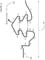
- Figure 15 shows an exemplary embodiment of the winding path of the seal with a leftmost horizontal length of the portion of the seal that is in contact with the corresponding portion on the other half of the seal.
- the length is 1.0.
- the lengths shown are only relative to one another; they are not expressed in any specific units.
- the total length 1503 of the winding boundary path is 17.5.
- the horizontal distance 1501 between the start and end of the path is 7.0.
- the path length is approximately 2.5 times the horizontal distance. This ratio of path length to horizontal distance is a quantification of the extent to which the boundary path winds and changes directions, which contributes to the sealing force and the leak resistance.
- Some embodiments of the invention have a boundary path length of at least twice the horizontal distance between the start and end of the path, for example if the horizontal portion of the contact area is larger or if the ridges on the seal are shorter, etc.
- other embodiments may have a path length that is at least 3 times, or at least 4 times or at least 5 times the horizontal distance between the start of the path and the end of the path.
- Other metrics for measuring the seal may include measuring the path of the boundary for the seal starting at a point where the seal diverges from the base of the seal, or a flat portion of the seal, along the path of contact between each side of the seal and to a point next to the original starting point back on the flat portion of the seal.
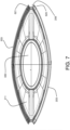
- Figure 7 shows a top view of the container before being inverted and Figure 8 shows a bottom view of the container before being inverted, according to one or more embodiments of the invention.
- One or more embodiments of the invention include forming the container 200 with a thickness of between 0.3 and 0.9 mm that increases to 1.2 to 2.4 mm at opposing sides 204, 205 of the leak resistant seal 203 at opposing ends of the container 200, for example at ends 550 and 560.
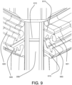
- Figure 9 shows a perspective view of ends of the leak resistant seal before being inverted to engage one another, according to one or more embodiments of the invention.
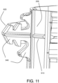
- Figure 10 shows a side view of a first side of the leak resistant seal before being inverted and
- Figure 11 shows a side view of a second side of the leak resistant seal before being inverted, according to one or more embodiments of the invention.
- the leak resistant seal 203 may include a gap seal 610 on the gap 206, and two gap seals 610 on the second seal portion 621, thus creating a three-level seal.
- the three-level seal is created from each of the three gap seals 610, wherein each gap seal 610 contact and engage with the flat surface of the gap 206 such that the three-way seal is created via each gap seal 610 layered above another gap seal 610 vertically along the gap 206.
- the first seal portion 620 and the second seal portion 621 include at least one corresponding protrusion or indentation 940, 950.
- Each protrusion or indentation shown may be a simple bump and groove or may include a geometric shape that is wider than another portion of the at least one corresponding protrusion or indentation 940, 950. This may include ridges or any other shape where the outer portion of the protrusion away from the surface on which the protrusion is located is larger than the corresponding entry to the indentation.
- the large male and female seal portions 620 and 621 may be produced on a smaller scale as gap seal components if desired.
- the gap 206 includes a gap seal 610 on a flat portion of the gap 206, and the first seal portion 620 includes a corresponding indentation that folds over and fits into the gap seal 610 of the gap 206, when inverting the container 200.
- utilizing the leak resistant seal 203 includes utilizing the protrusion or the indentation 940, 950 having a height of at least 2 mm and utilizing the geometric shape having a width of at least 1 mm thicker than the protrusion or the indentation 940, 950.
- utilizing the leak resistant seal 203 includes utilizing the protrusion or the indentation 940, 950 having a height of at least 2 mm and utilizing the geometric shape having a width of at least 2 mm thicker than the protrusion or the indentation 940, 950.
- utilizing the leak resistant seal 203 includes utilizing two or more of the at least one corresponding protrusion 940 and the at least one corresponding indentation 950 in the leak resistant seal 203.
- Figure 12 shows gap seals on the first side and the second side of the leak resistant seal before being inverted, according to one or more embodiments of the invention.
- the gap 206 may not include a gap seal.
- the side 204 and the second side 205 of the leak resistant seal 203 such as at the first seal portion 620 and at the second seal portion 621, may each include at least one gap seal 610, and the second seal portion 620 includes one gap seal 610, and the first seal portion 610 includes two gap seals 610.
- the gap seals 610 shown in Figure 12 fold over to contact the gap 206 in the center of the first seal portion 620 and the second seal portion 621, and thus create a three level seal where the gap 206 is thicker than the remaining portions of the outside of the container 200.
- the thicker portion of the gap 206 with the gap seals 610 in contact therewith provide more force and are stronger than the remaining portion of the gap 206 and provide force to engage the first side 204 and the second side 205.
- the container 200 includes wall edges on either side wall of the container 200 that includes the wall of the gap 206, wherein the wall of the gap 206 is thicker than the edges on either side of the container 200.
- the wall thickness of the wall of the gap 206 is thickened and tapers smoothly on both sides of the container 200 away from the wall of the gap 206 to create the container side walls, such that the side walls of the container 200 are thinner than the walls of the gaps 206 on both opposing edges 550, 560 of the container 200.
- the thicker portion of the container walls that includes the wall of the gap 206 includes additional material thickness on the internal surface 211 of the container 200, wherein such additional material thickness creates a clamping force when the container 200 is inverted, thus promoting and engaging a tight seal in the leak resistant seal 200.
- the gap 206 or each end of the first side 204 and second side 205 of the leak resistant seal 203 include at least one gap seal 610, wherein the at least one gap seal 610 is a protrusion that protrudes from the gap 206 as shown in Figure 6 , or from each end of the first side 204 and second side 205 of the leak resistant seal 203 as shown in Figure 12 .
- each end of the first side 204 and second side 205 may include a gap seal, or one end of one of the first side 204 and the second side 205 may include a gap seal, or the gap 206 may include a gap seal, or any combination thereof.
- the gap 206 may be thicker than a portion of the container 200, such that when the container 200 is inverted, a compressive force is developed from stretching of the material at the ends. This is the material thickness as looking into the figure, i.e., the thickness of the material in the gap region. This force, as applied, pulls the first seal portion 610 and the second seal portion 620 together at each and both ends of the seal portions, to provide a liquid tight barrier that is leak resistant for storage and transport, i.e., resists the leakage of liquids when external forces are applied to the container without requiring any external structure to hold the seal together.
- the width of the gap may be less than the height of element 621 for example to compress elements 620 and 621 together when inverted.
- Either the thickness of the material at the gap and/or the width of the gap may be made thicker and narrower alone or in combination to increase the sealing force at the ends of the leak resistant seal.
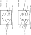
- Figure 16A shows an alternate embodiment of a seal profile having a gap on the external portion of the container to make the container easier to open from the outside than from the inside, wherein the outside of the container is on the right side of the figure.
- Figure 16B shows a second alternate embodiment of a seal profile having gaps, for example under one or more of the ridges when the seal is closed.
- the initial point of contact 1620 is where the first seal portion 1601, as shown primarily a female component, contacts second seal portion 1602, primarily a male component.
- a gap 1610 occurs where there is no contact between the first seal portion 1601 and second seal portion 1602.
- gap 1610 enables that right portion of the seal as shown to more easily open than the left portion.
- the seal includes four gaps, which make the seal easier to open in general.
- One or more of the gaps shown in Figure 16B are optional, such that the design may have gaps there or even above the uppermost point of the element 1602, i.e., a gap in element 1601, not shown for brevity.
- the path i.e., along the surface of either, (or even both) the first seal portion or second seal portion, is at least 2.5 times the horizontal distance between the start of the path 1620 and the end of said path 1630.
- the path begins at a base portion of the leak resistant seal, i.e., where the contact point moves vertical at 1640, and wherein the path is at least 4.5 times the horizontal distance between the start of the path and the end of the path, i.e., where the path moves down vertically at 1650 with respect to a base width of the leak resistant seal, specifically where the leak resistant seal diverges from a flat portion of the leak resistant seal.
- Elastomer - A material which at room temperature can be stretched repeatedly to at least twice its original length and, upon immediate release of the stress, will return with force to its approximate original length.
- Boundary a length of a surface of either the first seal portion or second seal portion between an initial point of contact and final point of contact between the first seal portion and second seal portion when the leak resistant seal is closed.
- the boundary is the same length whether measured along the surface of element 1601 or 1602.
- the boundary used for calculations of the path is either that length of the surface of either the first seal portion or second seal portion, wherein the female portion in general will have a larger boundary in a seal having gaps where no contact exists between some portions of the seal. Either the larger number or smaller number in this case can be utilized to show the length of the path. See also Figs. 16A-B .
- Leak resistant seal - A seal that resists leakage of liquids and solids from the container during storage and transport without the aid of an external structure to maintain the seal.
- the shapes of the protrusions and recesses may be of the same shape where there are no gaps in the seal or may be of different shapes if the seal has gaps, e.g., when closed.
- the protrusions and recesses may be of different shapes so that when closed, there is at least one contact boundary along the length of the seal.
- the corresponding indentations for ridges may be of the same shape or different shape.
Landscapes
- Engineering & Computer Science (AREA)
- Mechanical Engineering (AREA)
- Manufacturing & Machinery (AREA)
- Life Sciences & Earth Sciences (AREA)
- Food Science & Technology (AREA)
- Closures For Containers (AREA)
- Bag Frames (AREA)
- Lining Or Joining Of Plastics Or The Like (AREA)
- Packages (AREA)
Applications Claiming Priority (4)
| Application Number | Priority Date | Filing Date | Title |
|---|---|---|---|
| US16/193,978 US10407217B1 (en) | 2018-11-16 | 2018-11-16 | Method of manufacturing a container with a leak resistant seal |
| US16/566,779 US10625906B1 (en) | 2018-11-16 | 2019-09-10 | Inside out method of manufacturing a container with a leak resistant seal |
| EP19883646.2A EP3880571B1 (de) | 2018-11-16 | 2019-11-14 | Inside-out-verfahren zur herstellung eines behälters mit lecksicherer dichtung |
| PCT/US2019/061455 WO2020102517A1 (en) | 2018-11-16 | 2019-11-14 | Inside out method of manufacturing a container with a leak resistant seal |
Related Parent Applications (2)
| Application Number | Title | Priority Date | Filing Date |
|---|---|---|---|
| EP19883646.2A Division EP3880571B1 (de) | 2018-11-16 | 2019-11-14 | Inside-out-verfahren zur herstellung eines behälters mit lecksicherer dichtung |
| EP19883646.2A Division-Into EP3880571B1 (de) | 2018-11-16 | 2019-11-14 | Inside-out-verfahren zur herstellung eines behälters mit lecksicherer dichtung |
Publications (2)
| Publication Number | Publication Date |
|---|---|
| EP4512734A2 true EP4512734A2 (de) | 2025-02-26 |
| EP4512734A3 EP4512734A3 (de) | 2025-05-07 |
Family
ID=70284996
Family Applications (2)
| Application Number | Title | Priority Date | Filing Date |
|---|---|---|---|
| EP24222854.2A Pending EP4512734A3 (de) | 2018-11-16 | 2019-11-14 | Verfahren zum herstellen eines behälters mit einer lecksicheren dichtung |
| EP19883646.2A Active EP3880571B1 (de) | 2018-11-16 | 2019-11-14 | Inside-out-verfahren zur herstellung eines behälters mit lecksicherer dichtung |
Family Applications After (1)
| Application Number | Title | Priority Date | Filing Date |
|---|---|---|---|
| EP19883646.2A Active EP3880571B1 (de) | 2018-11-16 | 2019-11-14 | Inside-out-verfahren zur herstellung eines behälters mit lecksicherer dichtung |
Country Status (12)
| Country | Link |
|---|---|
| US (4) | US10625906B1 (de) |
| EP (2) | EP4512734A3 (de) |
| JP (2) | JP7550148B2 (de) |
| KR (2) | KR20260006717A (de) |
| CN (2) | CN113799320B (de) |
| AU (2) | AU2019380311B2 (de) |
| CA (1) | CA3118787A1 (de) |
| DK (1) | DK3880571T3 (de) |
| FI (1) | FI3880571T3 (de) |
| MX (2) | MX2021005661A (de) |
| PT (1) | PT3880571T (de) |
| WO (1) | WO2020102517A1 (de) |
Families Citing this family (26)
| Publication number | Priority date | Publication date | Assignee | Title |
|---|---|---|---|---|
| US10625906B1 (en) | 2018-11-16 | 2020-04-21 | Stasher, Inc. | Inside out method of manufacturing a container with a leak resistant seal |
| USD927297S1 (en) | 2020-11-24 | 2021-08-10 | Stasher, Inc. | Container |
| WO2022155105A1 (en) | 2021-01-12 | 2022-07-21 | Instant Brands Holdings Inc. | Silicone food and beverage storage containers |
| US11772849B2 (en) | 2021-06-18 | 2023-10-03 | S. C. Johnson & Son, Inc. | Closure system for pouch or container |
| USD975448S1 (en) * | 2021-08-27 | 2023-01-17 | Spacewhite Pty Ltd | Sealable bag |
| USD1084846S1 (en) | 2021-09-02 | 2025-07-22 | Stasher, Inc. | Container |
| USD1012727S1 (en) | 2021-10-01 | 2024-01-30 | Stasher, Inc. | Container |
| USD996978S1 (en) | 2021-10-01 | 2023-08-29 | Stasher, Inc. | Container |
| USD1011926S1 (en) | 2021-10-01 | 2024-01-23 | Stasher, Inc. | Container |
| USD1011927S1 (en) | 2021-10-01 | 2024-01-23 | Stasher, Inc. | Container |
| USD996224S1 (en) | 2021-11-05 | 2023-08-22 | Stasher, Inc. | Set of containers |
| USD994499S1 (en) | 2021-11-05 | 2023-08-08 | Stasher, Inc. | Container |
| USD1007327S1 (en) | 2021-11-05 | 2023-12-12 | Stasher, Inc. | Container |
| USD994500S1 (en) | 2021-11-05 | 2023-08-08 | Stasher, Inc. | Container |
| USD1022604S1 (en) * | 2022-01-11 | 2024-04-16 | Instant Brands Holdings Inc. | Combined food and beverage storage container |
| USD1044409S1 (en) | 2022-01-11 | 2024-10-01 | Instant Brands Holdings Inc. | Food and beverage storage container |
| USD1045508S1 (en) | 2022-01-11 | 2024-10-08 | Instant Brands Holdings Inc. | Food and beverage storage container |
| USD1022606S1 (en) * | 2022-01-11 | 2024-04-16 | Instant Brands Holdings Inc. | Combined food and beverage storage container |
| USD1044408S1 (en) | 2022-01-11 | 2024-10-01 | Instant Brands Holdings Inc. | Food and beverage storage container |
| USD1022605S1 (en) * | 2022-01-11 | 2024-04-16 | Instant Brands Holdings Inc. | Combined food and beverage storage container |
| USD1052961S1 (en) | 2022-10-06 | 2024-12-03 | Stasher, Inc. | Container |
| USD1101509S1 (en) | 2022-10-06 | 2025-11-11 | Stasher, Inc. | Container |
| USD1100601S1 (en) | 2022-10-06 | 2025-11-04 | Stasher, Inc. | Container |
| USD1030472S1 (en) | 2022-11-17 | 2024-06-11 | Stasher, Inc. | Container |
| USD1092198S1 (en) | 2023-12-27 | 2025-09-09 | Kaz Europe Sàrl | Reusable silicone bag |
| USD1082519S1 (en) | 2023-12-28 | 2025-07-08 | Kaz Europe Sárl | Reusable silicone bag |
Citations (6)
| Publication number | Priority date | Publication date | Assignee | Title |
|---|---|---|---|---|
| US2674289A (en) | 1951-02-02 | 1954-04-06 | Silverman | |
| US2780261A (en) | 1954-10-26 | 1957-02-05 | Flexigrip Inc | Sliderless fastener closure |
| US5000363A (en) | 1989-08-18 | 1991-03-19 | Linquist Phillip A | Carrier for transporting objects on a motor vehicle |
| US20090110335A1 (en) | 2007-10-30 | 2009-04-30 | Leboeuf William E | Durable freezer to conventional oven bag with mating seal |
| US20130105352A1 (en) | 2011-11-01 | 2013-05-02 | Mark Munguia | Reusable seamless multipurpose bag |
| US20140270579A1 (en) | 2013-03-12 | 2014-09-18 | Modern-twist, Inc. | Silicone bag with seal |
Family Cites Families (176)
| Publication number | Priority date | Publication date | Assignee | Title |
|---|---|---|---|---|
| US1991943A (en) * | 1933-10-27 | 1935-02-19 | Laszlo V Keviczky | Waterproof closing means |
| US2115424A (en) * | 1935-08-31 | 1938-04-26 | Lesti Geno | Closure |
| US2220693A (en) * | 1936-06-27 | 1940-11-05 | Universal Oil Prod Co | Isomerization of olefins |
| GB521093A (en) | 1938-08-09 | 1940-05-13 | Gyoergy Forro | Improvements in or relating to the manufacture of hollow articles by dipping or moulding |
| US2296468A (en) * | 1942-01-05 | 1942-09-22 | John H Feist | Slide fastener |
| US2306873A (en) * | 1942-06-09 | 1942-12-29 | John H Feist | Slide fastener |
| US2545817A (en) * | 1943-03-04 | 1951-03-20 | Goodrich Co B F | Sealing closure |
| US2500363A (en) | 1946-03-11 | 1950-03-14 | Scovill Manufacturing Co | Container and closure means therefor |
| US2519290A (en) * | 1946-03-11 | 1950-08-15 | Rogers Imp S Inc | Tobacco pocket and closure means therefor |
| US2746113A (en) * | 1946-04-10 | 1956-05-22 | Harvey L Williams | Water tight fastener |
| US2551245A (en) * | 1948-12-20 | 1951-05-01 | James A Cook | Slide fastener closure |
| US2746502A (en) * | 1954-02-15 | 1956-05-22 | Graell Alberto Camprubi | Bag with integral closing means |
| US2823721A (en) | 1954-10-26 | 1958-02-18 | Flexigrip Inc | Sliderless fastener closure |
| USRE29331E (en) | 1961-02-15 | 1977-08-02 | Kabushiki Kaisha Seisan Nihon Sha | Method and structure for reclosable containers |
| USRE28969E (en) | 1961-11-27 | 1976-09-21 | Kabushiki Kaisha Seisan Nihon Sha Ltd. | Integral reclosable bag |
| US3149747A (en) | 1961-12-28 | 1964-09-22 | Gen Motors Corp | Snap-on connected plate structure |
| DE1435791A1 (de) | 1963-11-23 | 1969-02-20 | Jaster Geb Krupska Margarete J | Verpackung oder Ummantelung aus Kunststoff |
| US3275053A (en) * | 1964-03-16 | 1966-09-27 | Joseph A Kabana | Purse and method of manufacturing the same |
| US3280870A (en) | 1964-03-30 | 1966-10-25 | William C Bundy | Receptacle |
| US3417675A (en) | 1965-03-10 | 1968-12-24 | Ausnit Steven | Method of making a plastic bag and a magnetic sliderless fastener therefor |
| US3326399A (en) | 1965-03-10 | 1967-06-20 | Ausnit Steven | Magnetic plastic fastener and method of making same |
| US3417406A (en) * | 1966-08-16 | 1968-12-24 | Donald A. Rosenbaum | Pressure sealing closure |
| US3591914A (en) * | 1969-04-21 | 1971-07-13 | Opti Holding Ag | Method and apparatus for making fluidtight slide fastener |
| US3746215A (en) | 1971-01-29 | 1973-07-17 | A Ausnit | Reclosable sealed pouring bag |
| BE786706A (fr) | 1971-07-26 | 1973-01-25 | Flexico France Sarl | Perfectionnements apportes aux fermetures et aux sacs munis de telles fermetures |
| US3948705A (en) | 1972-07-25 | 1976-04-06 | Steven Ausnit | Method for making multiple plastic bags with reclosable fasteners thereon |
| US3945403A (en) | 1973-04-19 | 1976-03-23 | Minigrip, Inc. | Tube construction for fastener profile strips |
| GB1549021A (en) | 1975-02-28 | 1979-08-01 | Artusi A | One-piece deepdrawn package form and the use thereof |
| FR2329439A1 (fr) | 1975-11-03 | 1977-05-27 | Flexico France Sarl | Procede et machine pour la reunion d'une feuille a au moins une bande portant un profile d'accouplement, les produits obtenus et leurs parties |
| US4159728A (en) | 1977-03-12 | 1979-07-03 | Gummi-Kraus Gmbh | Hot water bag |
| US4199845A (en) | 1978-02-08 | 1980-04-29 | Minigrip, Inc. | Slider for heavy duty flexible fastener tracks |
| US4193152A (en) * | 1978-03-01 | 1980-03-18 | Seibold Charles R Jr | Closeable pillow, tote bag and the like |
| US4397404A (en) | 1981-09-28 | 1983-08-09 | Plastican, Incorporated | Plastic containers and covers |
| US4736496A (en) | 1982-12-27 | 1988-04-12 | The Dow Chemical Company | Closure for thermoplastic containers |
| US4512474A (en) | 1983-12-08 | 1985-04-23 | Plastofilm Industries, Inc. | Locking means for display package |
| US4562934A (en) * | 1984-04-30 | 1986-01-07 | Owens-Corning Fiberglas Corporation | Glass fiber reinforced resin tank with particular joint structure |
| JPH0216648Y2 (de) * | 1985-07-27 | 1990-05-09 | ||
| US4842670A (en) | 1986-03-07 | 1989-06-27 | Northrop Corporation | Molded vacuum bag for debulking and autoclaving laminates of complex shapes |
| JPH053050Y2 (de) * | 1986-12-26 | 1993-01-26 | ||
| US4929487A (en) | 1987-09-14 | 1990-05-29 | Minigrip, Inc. | Bag making material having fastener profiles and alignment ribs with reinforcing and stabilizing beam effect ridge means |
| US4845781A (en) | 1988-01-27 | 1989-07-11 | Vadax, Inc. | Disposable hand covering for handling contaminated material |
| US4912616A (en) * | 1988-04-15 | 1990-03-27 | Minigrip, Inc. | Bag with infold along flange for differential opening force |
| DK576888D0 (da) | 1988-10-17 | 1988-10-17 | Schur Int As Brdr | Fremgangsmaade ved fremstilling af poseemballager med oprivelig svejselukning, saadanne emballager med genlukningsprofildele, samt hjaelpemateriale til brug ved denne fremstilling |
| US5017021A (en) | 1989-05-19 | 1991-05-21 | Reynolds Consumer Products, Inc. | Reclosable profile having improved closure members |
| USD323979S (en) | 1989-09-14 | 1992-02-18 | Forman Harold M | Tamper evident, resealable bag |
| US5067639A (en) | 1989-09-27 | 1991-11-26 | Maguire Paul R | Pouring spout which can be selectively opened and closed |
| US5000360A (en) | 1989-09-27 | 1991-03-19 | John Lown | Pouring spout which can be selectively opened and closed |
| US5134812A (en) * | 1990-04-04 | 1992-08-04 | Ingalls Shipbuilding, Inc. | Mechanical connector for structural members |
| US5031768A (en) | 1990-04-09 | 1991-07-16 | Ultradent Products, Inc. | Instrument tray and disposable receptacle having alternative locking means |
| US5094707A (en) | 1990-07-25 | 1992-03-10 | Bruno Edward C | Apparatus for extruding plastic storage bags |
| US5111977A (en) | 1990-08-24 | 1992-05-12 | Maguire Paul R | Sealable and dispensing pouring spout |
| US5046659A (en) | 1990-11-13 | 1991-09-10 | Mobil Oil Corporation | Latching structure for food container |
| US5123535A (en) | 1991-01-24 | 1992-06-23 | Minnesota Mining And Manufacturing Company | Sterile holder for x-ray cassettes |
| US5161286A (en) | 1991-03-22 | 1992-11-10 | Mobil Oil Corporation | End clamp stops for plastic reclosable fastener |
| US5174658A (en) | 1991-07-12 | 1992-12-29 | The Procter & Gamble Company | Self-expanding and reclosable flexible pouch |
| US5235731A (en) | 1992-03-26 | 1993-08-17 | Kuraray Co., Ltd. | Molded-resin separable fastener and fastening system utilizing the same |
| US5253395A (en) * | 1992-06-26 | 1993-10-19 | Yoshida Kogyo K. K. | Watertight slide fastener |
| US5365713A (en) * | 1992-12-14 | 1994-11-22 | Pawling Corporation | Elastomeric seismic seal system |
| US6049938A (en) * | 1993-06-18 | 2000-04-18 | Jimison; James W. | Method and apparatus for cleaning and polishing fruits and vegetables |
| US5375666A (en) * | 1993-07-23 | 1994-12-27 | Ryobi Outdoor Products | Vibration isolator for a portable power tool |
| JPH08126975A (ja) * | 1994-10-28 | 1996-05-21 | Hitachi Koki Co Ltd | 電気ハンマの防振ハンドル |
| US5560106A (en) * | 1993-11-09 | 1996-10-01 | Armbruster; Joseph M. | Resilient floating head razor |
| US5381920A (en) * | 1993-12-21 | 1995-01-17 | Lin; Arlo H. T. | Tool box hinge structure |
| US5486051A (en) | 1994-04-11 | 1996-01-23 | Reynolds Consumer Products Inc. | Closure arrangement having a breakaway seal |
| DE4419967A1 (de) * | 1994-06-08 | 1995-12-14 | Freudenberg Carl Fa | Dichtung |
| US5713111A (en) * | 1994-07-27 | 1998-02-03 | Minnesota Mining And Manufacturing Company | Method for making an interengaging fastener having reduced engagement force |
| US5469982A (en) * | 1994-08-23 | 1995-11-28 | Motorola, Inc. | Four-sided housing latch |
| JPH08217093A (ja) | 1995-02-16 | 1996-08-27 | Reiko Miwa | ビニール袋 |
| US5577305A (en) | 1995-05-08 | 1996-11-26 | Johnson; James R. | Fastener assembly |
| US5729876A (en) | 1995-05-08 | 1998-03-24 | Ami/Recpro, Inc. | Fastener assembly |
| ITFO950006A1 (it) * | 1995-05-10 | 1995-08-08 | Federico Rossi | Contenitore/bracciale/gambale/collare porta valori e piccoli oggetti impermeabile all'acqua applicabile solidalmente agli arti umani o al |
| US5665301A (en) | 1995-07-11 | 1997-09-09 | Arctek Inc. | Apparatus and method for forming fiber reinforced composite articles |
| JP3529503B2 (ja) * | 1995-07-25 | 2004-05-24 | 出光石油化学株式会社 | 咬合具及び咬合具付き袋 |
| US5709915A (en) | 1995-08-04 | 1998-01-20 | Reynolds Consumer Products, Inc. | Adhesive structure for heat sealing |
| US5686304A (en) | 1995-12-15 | 1997-11-11 | Avecor Cardiovascular, Inc. | Cell culture apparatus and method |
| US5584408A (en) | 1996-03-05 | 1996-12-17 | Inline Plastics Corporation | Latching structure for food container |
| US5678830A (en) * | 1996-07-15 | 1997-10-21 | Chang; Hsin Yan | Wire cover packing ring of an electric fan |
| US5802677A (en) | 1996-11-06 | 1998-09-08 | Lilly Industries (Usa), Inc. | Bag closure clip |
| JP3474735B2 (ja) * | 1997-08-20 | 2003-12-08 | Ykk株式会社 | 一体成形面ファスナー |
| US6063224A (en) | 1998-05-22 | 2000-05-16 | Reynolds Consumer Products, Inc. | Method for separate closure extrusion |
| FR2780037B1 (fr) | 1998-06-17 | 2000-09-08 | Flexico France Sarl | Sachet comprenant des profiles de fermeture complementaires actionnes par curseur |
| US6991375B2 (en) | 1998-11-06 | 2006-01-31 | Velcro Industries B.V. | Reclosable packaging |
| JP2000303022A (ja) | 1999-04-21 | 2000-10-31 | Dow Corning Toray Silicone Co Ltd | エアーバッグ用シリコーンゴム系コーティング剤組成物 |
| JP2001031138A (ja) | 1999-07-19 | 2001-02-06 | Fuji Seal Inc | 収納袋 |
| US6632164B1 (en) | 1999-09-27 | 2003-10-14 | Stephen Warburton-Pitt | Silicone bag assembly manufacturing apparatus |
| WO2001044102A2 (en) * | 1999-11-10 | 2001-06-21 | Capitol Vial, Inc. | A tamper-proof container cap assembly and related methods |
| DE10005976A1 (de) * | 2000-02-10 | 2001-08-16 | Bosch Gmbh Robert | Staubbehälter |
| JP4194229B2 (ja) * | 2000-03-07 | 2008-12-10 | 株式会社細川洋行 | 再閉自在包装袋およびその製造方法 |
| US7793391B2 (en) * | 2000-03-14 | 2010-09-14 | Com-Pac International, Inc. | Flangeless reclosable fastener |
| US6954969B1 (en) * | 2000-03-14 | 2005-10-18 | Com-Pac International, Inc. | Reclosable fastener strip |
| US6705463B1 (en) * | 2000-06-07 | 2004-03-16 | Csp Technologies, Inc. | Flip top golf ball container assembly provided with moisture barrier properties |
| US6625955B2 (en) | 2000-06-28 | 2003-09-30 | Aylward Enterprises, Inc. | Methods for forming product package with recloseable locking mechanism |
| US6572267B1 (en) * | 2000-10-23 | 2003-06-03 | Sealstrip Corporation | Gussetted packages |
| GB0028780D0 (en) * | 2000-11-25 | 2001-01-10 | Novamedix Distrib Ltd | A method of joining plastics sheet materials |
| US20050061524A1 (en) * | 2001-01-23 | 2005-03-24 | Hagan Todd A. | Housing with functional overmold |
| US7032773B2 (en) | 2001-05-25 | 2006-04-25 | Fort James Corporation | Food container with interchangeable lid—base seal provided with undercut sealing profile and asymmetric interlockable stacking ridges |
| JP4351403B2 (ja) * | 2001-07-23 | 2009-10-28 | 株式会社細川洋行 | ジッパ袋及びその製造方法 |
| US7291370B2 (en) | 2001-08-08 | 2007-11-06 | Milliken & Company | Packaging material and containers formed therefrom |
| US6594872B2 (en) | 2001-08-17 | 2003-07-22 | The Glad Products Company | Interlocking closure device |
| US6994354B2 (en) * | 2002-01-15 | 2006-02-07 | Freudenberg-Nok General Partnership | Vibrationally decoupling gasket |
| US7159282B2 (en) | 2002-03-01 | 2007-01-09 | Pactiv Corporation | Reclosable fasteners or zippers for use with polymeric bags |
| US7048442B2 (en) | 2002-05-15 | 2006-05-23 | Illinois Tool Works Inc. | Reclosable packaging for scoopable products and method of manufacture |
| US7018142B2 (en) * | 2002-07-16 | 2006-03-28 | Black & Decker Inc. | Power tool with integral gripping member |
| US7819279B2 (en) | 2002-08-14 | 2010-10-26 | International Molded Packaging Corporation | Latchable container system |
| US7189001B2 (en) | 2003-01-02 | 2007-03-13 | Reynolds Consumer Products, Inc. | Liquid tight locking arrangement with sealing fingers |
| US20040134166A1 (en) | 2003-01-10 | 2004-07-15 | Steven Ausnit | Method for dual manufacture of reclosable bags on HFVF machine |
| US7300207B2 (en) | 2003-04-16 | 2007-11-27 | Ron Linneweil | Closure for containers and reclosable containers including the same |
| DE10335325B4 (de) | 2003-08-01 | 2007-05-03 | Gea Niro Gmbh | Kupplungsverschlüsse sowie Andockeinrichtungen enthaltend diese Kupplungsverschlüsse |
| USD512650S1 (en) | 2003-09-26 | 2005-12-13 | Kenzo | Flask for perfumery products |
| CN101342960B (zh) | 2003-11-21 | 2012-01-04 | 葛西寿一 | 一种高气密性塑料夹头及具有该夹头的袋体 |
| US7597206B2 (en) | 2004-04-26 | 2009-10-06 | Dart Container Corporation | Container with one-step closing |
| US7347624B2 (en) * | 2004-04-30 | 2008-03-25 | The Glad Products Company | Tie bag |
| US7347908B2 (en) * | 2004-07-21 | 2008-03-25 | Illinois Tool Works Inc. | Leakproof zipper end crush for reclosable bag and related method of manufacture |
| FR2873998B1 (fr) * | 2004-08-06 | 2007-12-21 | Schweitzer Sas Soc Par Actions | Sac en matiere plastique souple muni d'un lien coulissant avec un double adhesif |
| US20060083833A1 (en) | 2004-09-16 | 2006-04-20 | Newell Sa | Flexible mould for foodstuff |
| JP4857542B2 (ja) * | 2004-10-29 | 2012-01-18 | 日立工機株式会社 | 動力工具 |
| US7316052B2 (en) | 2005-01-31 | 2008-01-08 | S.C. Johnson Home Storage, Inc. | Closure profile and die plate for extruding same |
| US7585111B2 (en) | 2005-01-31 | 2009-09-08 | S.C. Johnson Home Storage, Inc. | Reclosable pouch and closure element therefor having interlocking closure profiles |
| US8157123B2 (en) | 2005-02-23 | 2012-04-17 | The Glad Products Company | Container |
| ITBO20050196A1 (it) | 2005-03-25 | 2006-09-26 | Infia Srl | Contenitore per il confezionamento di prodotti,in particolare di prodotti ortofrutticoli |
| CN2789164Y (zh) * | 2005-04-11 | 2006-06-21 | 曹良保 | 一种液体密封容器 |
| JP4628233B2 (ja) * | 2005-09-29 | 2011-02-09 | Ykk株式会社 | スライドファスナーの防水用上止 |
| US20070086683A1 (en) * | 2005-10-18 | 2007-04-19 | Yeager James W | Package having recloseable pour spout |
| DE502005007679D1 (de) * | 2005-10-29 | 2009-08-20 | Aeg Electric Tools Gmbh | Handwerkzeugmaschine |
| US9011003B2 (en) | 2006-02-08 | 2015-04-21 | S.C. Johnson Home Storage, Inc. | Reclosable pouch and zipper for a reclosable pouch |
| US8146762B2 (en) | 2006-03-09 | 2012-04-03 | Nalge Nunc International Corporation | Flexible container handling system |
| US8105638B2 (en) | 2006-11-16 | 2012-01-31 | C-Pak, Llc | Reclosable package for a product |
| US20100175230A1 (en) * | 2006-11-19 | 2010-07-15 | Kelsey William D | Locking Mechanisms For Use With Devices For Forming A Closure Between Materials |
| WO2008094264A1 (en) * | 2007-01-31 | 2008-08-07 | Agere Systems Inc. | Reversible fastener for a resealable bag-type container |
| JP4689631B2 (ja) * | 2007-02-08 | 2011-05-25 | Ykk株式会社 | 液密スライドファスナー並びに液密スライドファスナーの製造方法 |
| US7850055B2 (en) * | 2007-03-15 | 2010-12-14 | Black & Decker Inc. | Assembly having gasket resistant to side loading by pressurized fluid |
| FR2917275A1 (fr) * | 2007-06-13 | 2008-12-19 | Aplix Sa | Dispositif auto-agrippant a crochets a grande souplesse |
| US7827950B2 (en) * | 2007-06-27 | 2010-11-09 | Federal-Mogul Corporation | Valve cover assembly and method of construction |
| DE102007030703A1 (de) * | 2007-07-02 | 2009-01-08 | Robert Bosch Gmbh | Elastische Verbindung zwischen Gehäuseteilen motorisch angetriebener Werkzeugmaschinen |
| PT2193731E (pt) | 2007-09-07 | 2011-01-06 | Lekue S L | Recipiente para alimentos para utilizar no cozinhar em micro-ondas |
| US20090106953A1 (en) * | 2007-10-24 | 2009-04-30 | Wittig Wayne | Apparatus and method for fastening by capturing protruding members in corresponding flexible openings |
| US8167166B2 (en) | 2007-11-23 | 2012-05-01 | Peninsula Packaging, Llc | Container |
| US8091731B2 (en) | 2007-11-28 | 2012-01-10 | Peninsula Packaging, Llc | Container |
| US8261933B2 (en) | 2007-11-28 | 2012-09-11 | Peninsula Packaging, Llc | Container |
| US7681732B2 (en) | 2008-01-11 | 2010-03-23 | Cryovac, Inc. | Laminated lidstock |
| JP5426889B2 (ja) | 2009-01-26 | 2014-02-26 | 株式会社クレハ | ジッパ付き包装袋 |
| US7891514B1 (en) | 2009-01-27 | 2011-02-22 | Raymond Walsh | Easy open air-tight sealed food container |
| US20110038564A1 (en) | 2009-08-14 | 2011-02-17 | Cindy Ann Slansky | Reusable silicone bag |
| US20110268373A1 (en) | 2010-05-03 | 2011-11-03 | Alex Polland | Pull tabs for a flexible plastic bag |
| US20120008880A1 (en) | 2010-07-06 | 2012-01-12 | Landy Toth | Isolation system for a mobile computing device |
| ES1073950Y (es) | 2010-08-10 | 2011-06-06 | Lekue Sl | Recipiente de cocina flexible |
| US8974118B2 (en) | 2010-10-29 | 2015-03-10 | S.C. Johnson & Son, Inc. | Reclosable bag having a sound producing zipper |
| US20130243354A1 (en) * | 2010-11-23 | 2013-09-19 | Matthew Mark Lytle | Self sealing waterproof bag |
| US10051946B1 (en) | 2011-01-19 | 2018-08-21 | Hydrapak, Inc. | Reservoir system and method of use |
| US20140193102A1 (en) * | 2011-08-31 | 2014-07-10 | Angela Weir | Easy Open Storage Bag Container |
| US8875356B2 (en) | 2011-10-06 | 2014-11-04 | Intercontinental Great Brands Llc | Mechanical and adhesive based reclosable fasteners |
| USD724441S1 (en) | 2011-12-28 | 2015-03-17 | Otsuka Pharmaceutical Co., Ltd. | Packaging bag |
| CN102991826A (zh) * | 2012-11-16 | 2013-03-27 | 上海南汇石森百货烟糖经营部 | 一种水果保鲜袋 |
| CN202987764U (zh) * | 2012-12-13 | 2013-06-12 | 张翔蔚 | 一种便携式食物保鲜袋 |
| US9156593B2 (en) | 2013-03-15 | 2015-10-13 | Reynolds Presto Products Inc. | Closure arrangements for recloseable pouches; recloseable pouches; and, methods |
| JP2015016018A (ja) | 2013-07-09 | 2015-01-29 | シーアイ化成株式会社 | 嵌合具及び嵌合具付き袋体 |
| GB201312986D0 (en) * | 2013-07-19 | 2013-09-04 | Grant William & Sons Ltd | Closure device, apparatus and method |
| WO2015057643A1 (en) * | 2013-10-14 | 2015-04-23 | 24M Technologies, Inc. | Curved battery container |
| CN203877286U (zh) * | 2014-02-22 | 2014-10-15 | 江苏中恒宠物用品股份有限公司 | 宠物用可自封口连卷垃圾袋 |
| US11285686B2 (en) * | 2014-05-21 | 2022-03-29 | Idemitsu Unitech Co., Ltd. | Zipper tape-equipped bag body, article housing method for zipper tape-equipped bag body, manufacturing method for zipper tape-equipped bag body, and manufacturing device for zipper tape-equipped bag body |
| US20170225842A1 (en) * | 2014-11-06 | 2017-08-10 | Agit Global Ip Holdings, Llc | Watertight bag |
| US9371153B1 (en) | 2015-03-04 | 2016-06-21 | Modern Twist, Inc. | Shaped elastomeric container with integrated leak resistant seal |
| US20170231245A1 (en) * | 2016-02-15 | 2017-08-17 | Zingerman's Coffee Company, LLC | Method of forming a shelf-stable ready-to-drink coffee product |
| US10582743B2 (en) * | 2016-03-21 | 2020-03-10 | Delphini, Llc | System and method for activated interlocking fasteners and seals |
| CN205770847U (zh) * | 2016-05-16 | 2016-12-07 | 德清尚邑塑料制品有限公司 | 加强型夹链式自封袋 |
| US20180029324A1 (en) | 2016-07-27 | 2018-02-01 | Poly-America, L.P. | Reclosable polymeric bag |
| CN206265553U (zh) * | 2016-11-01 | 2017-06-20 | 合肥茂康卫生材料有限公司 | 一种便于使用的双层自封袋 |
| US11358755B2 (en) | 2017-03-02 | 2022-06-14 | Zip Top Llc | Flexible foodstuff container with closure |
| CN207450635U (zh) * | 2017-10-16 | 2018-06-05 | 湖南宝泓科技有限公司 | 医疗废物专用袋 |
| TWM558230U (zh) * | 2017-12-26 | 2018-04-11 | Taiwan Central Science Biological Technology Co Ltd | 密封袋 |
| US10765461B2 (en) * | 2018-06-01 | 2020-09-08 | DePuy Synthes Products, Inc. | Variable angle bone fixation device |
| US10407217B1 (en) * | 2018-11-16 | 2019-09-10 | Stasher, Inc. | Method of manufacturing a container with a leak resistant seal |
| US10625906B1 (en) * | 2018-11-16 | 2020-04-21 | Stasher, Inc. | Inside out method of manufacturing a container with a leak resistant seal |
| US11873143B2 (en) | 2020-02-06 | 2024-01-16 | Stasher, Inc. | Shaped elastomeric container with integrated leak resistant seal and pressure shield |
| US11124330B2 (en) | 2020-02-06 | 2021-09-21 | Stasher, Inc. | Shaped elastomeric container with integrated leak resistant seal and pressure shield |
| WO2022184799A1 (en) * | 2021-03-05 | 2022-09-09 | Medos International Sarl | Multi-feature polyaxial screw |
-
2019
- 2019-09-10 US US16/566,779 patent/US10625906B1/en active Active
- 2019-11-14 CN CN202110943674.5A patent/CN113799320B/zh active Active
- 2019-11-14 WO PCT/US2019/061455 patent/WO2020102517A1/en not_active Ceased
- 2019-11-14 EP EP24222854.2A patent/EP4512734A3/de active Pending
- 2019-11-14 AU AU2019380311A patent/AU2019380311B2/en active Active
- 2019-11-14 KR KR1020267000162A patent/KR20260006717A/ko active Pending
- 2019-11-14 MX MX2021005661A patent/MX2021005661A/es unknown
- 2019-11-14 EP EP19883646.2A patent/EP3880571B1/de active Active
- 2019-11-14 FI FIEP19883646.2T patent/FI3880571T3/fi active
- 2019-11-14 CN CN201911112883.4A patent/CN111196008B/zh active Active
- 2019-11-14 PT PT198836462T patent/PT3880571T/pt unknown
- 2019-11-14 CA CA3118787A patent/CA3118787A1/en active Pending
- 2019-11-14 JP JP2021525591A patent/JP7550148B2/ja active Active
- 2019-11-14 DK DK19883646.2T patent/DK3880571T3/da active
- 2019-11-14 KR KR1020217018376A patent/KR102909205B1/ko active Active
-
2020
- 2020-03-12 US US16/816,281 patent/US11279526B2/en active Active
-
2021
- 2021-05-13 MX MX2025011660A patent/MX2025011660A/es unknown
-
2022
- 2022-03-03 US US17/685,989 patent/US11787600B2/en active Active
- 2022-03-22 US US17/700,667 patent/US11731809B2/en active Active
-
2024
- 2024-06-21 JP JP2024100359A patent/JP2024120062A/ja active Pending
-
2025
- 2025-06-20 AU AU2025204674A patent/AU2025204674A1/en active Pending
Patent Citations (7)
| Publication number | Priority date | Publication date | Assignee | Title |
|---|---|---|---|---|
| US2674289A (en) | 1951-02-02 | 1954-04-06 | Silverman | |
| US2780261A (en) | 1954-10-26 | 1957-02-05 | Flexigrip Inc | Sliderless fastener closure |
| US5000363A (en) | 1989-08-18 | 1991-03-19 | Linquist Phillip A | Carrier for transporting objects on a motor vehicle |
| US20090110335A1 (en) | 2007-10-30 | 2009-04-30 | Leboeuf William E | Durable freezer to conventional oven bag with mating seal |
| US20130105352A1 (en) | 2011-11-01 | 2013-05-02 | Mark Munguia | Reusable seamless multipurpose bag |
| US20140270579A1 (en) | 2013-03-12 | 2014-09-18 | Modern-twist, Inc. | Silicone bag with seal |
| WO2014163712A1 (en) | 2013-03-12 | 2014-10-09 | Nouri Kat | Silicone bag with seal |
Also Published As
| Publication number | Publication date |
|---|---|
| EP3880571A4 (de) | 2022-07-20 |
| CA3118787A1 (en) | 2020-05-22 |
| US10625906B1 (en) | 2020-04-21 |
| CN111196008A (zh) | 2020-05-26 |
| FI3880571T3 (fi) | 2025-07-23 |
| MX2025011660A (es) | 2025-11-03 |
| EP4512734A3 (de) | 2025-05-07 |
| US11279526B2 (en) | 2022-03-22 |
| MX2021005661A (es) | 2021-09-08 |
| US11731809B2 (en) | 2023-08-22 |
| EP3880571B1 (de) | 2025-06-04 |
| US20220212835A1 (en) | 2022-07-07 |
| CN111196008B (zh) | 2021-08-31 |
| DK3880571T3 (da) | 2025-06-30 |
| CN113799320B (zh) | 2023-08-08 |
| PT3880571T (pt) | 2025-07-03 |
| KR20210108371A (ko) | 2021-09-02 |
| AU2019380311A1 (en) | 2021-06-03 |
| JP2022507158A (ja) | 2022-01-18 |
| JP2024120062A (ja) | 2024-09-03 |
| CN113799320A (zh) | 2021-12-17 |
| KR102909205B1 (ko) | 2026-01-09 |
| US11787600B2 (en) | 2023-10-17 |
| AU2019380311B2 (en) | 2025-04-03 |
| AU2025204674A1 (en) | 2025-07-10 |
| US20200207520A1 (en) | 2020-07-02 |
| WO2020102517A1 (en) | 2020-05-22 |
| US20220185544A1 (en) | 2022-06-16 |
| KR20260006717A (ko) | 2026-01-13 |
| EP3880571A1 (de) | 2021-09-22 |
| JP7550148B2 (ja) | 2024-09-12 |
Similar Documents
| Publication | Publication Date | Title |
|---|---|---|
| US11787600B2 (en) | Container having a leak resistant seal | |
| US10407217B1 (en) | Method of manufacturing a container with a leak resistant seal | |
| US20240109684A1 (en) | Elastomeric container with integrated leak resistant seal and pressure shield | |
| US11873143B2 (en) | Shaped elastomeric container with integrated leak resistant seal and pressure shield | |
| HK40124008A (en) | Inside out method of manufacturing a container with a leak resistant seal | |
| HK40057035B (zh) | 由内而外制造具有防漏密封件的容器的方法 | |
| HK40057035A (en) | Inside out method of manufacturing a container with a leak resistant seal | |
| HK40030139A (en) | Inside out method of manufacturing a container with a leak resistant seal | |
| HK40030139B (en) | Inside out method of manufacturing a container with a leak resistant seal | |
| CN121285515A (zh) | 用于袋或容器的闭合系统 | |
| HK40081678A (en) | Shaped elastomeric container with integrated leak resistant seal and pressure shield | |
| HK40081678B (en) | Shaped elastomeric container with integrated leak resistant seal and pressure shield |
Legal Events
| Date | Code | Title | Description |
|---|---|---|---|
| PUAI | Public reference made under article 153(3) epc to a published international application that has entered the european phase |
Free format text: ORIGINAL CODE: 0009012 |
|
| STAA | Information on the status of an ep patent application or granted ep patent |
Free format text: STATUS: THE APPLICATION HAS BEEN PUBLISHED |
|
| AC | Divisional application: reference to earlier application |
Ref document number: 3880571 Country of ref document: EP Kind code of ref document: P |
|
| AK | Designated contracting states |
Kind code of ref document: A2 Designated state(s): AL AT BE BG CH CY CZ DE DK EE ES FI FR GB GR HR HU IE IS IT LI LT LU LV MC MK MT NL NO PL PT RO RS SE SI SK SM TR |
|
| REG | Reference to a national code |
Ref country code: DE Ref legal event code: R079 Free format text: PREVIOUS MAIN CLASS: B65D0033020000 Ipc: B29C0043140000 |
|
| PUAL | Search report despatched |
Free format text: ORIGINAL CODE: 0009013 |
|
| AK | Designated contracting states |
Kind code of ref document: A3 Designated state(s): AL AT BE BG CH CY CZ DE DK EE ES FI FR GB GR HR HU IE IS IT LI LT LU LV MC MK MT NL NO PL PT RO RS SE SI SK SM TR |
|
| RIC1 | Information provided on ipc code assigned before grant |
Ipc: B29L 31/00 20060101ALN20250402BHEP Ipc: B29C 45/00 20060101ALI20250402BHEP Ipc: B65D 33/02 20060101ALI20250402BHEP Ipc: B65D 33/16 20060101ALI20250402BHEP Ipc: B65B 51/00 20060101ALI20250402BHEP Ipc: B29C 45/14 20060101ALI20250402BHEP Ipc: B29C 45/02 20060101ALI20250402BHEP Ipc: B29C 43/18 20060101ALI20250402BHEP Ipc: B65D 33/25 20060101ALI20250402BHEP Ipc: B29C 43/14 20060101AFI20250402BHEP |
|
| REG | Reference to a national code |
Ref country code: HK Ref legal event code: DE Ref document number: 40124008 Country of ref document: HK |
|
| STAA | Information on the status of an ep patent application or granted ep patent |
Free format text: STATUS: REQUEST FOR EXAMINATION WAS MADE |
|
| 17P | Request for examination filed |
Effective date: 20251107 |