EP4512702A2 - Kettenfahrzeug mit einer benutzerschnittstelle - Google Patents
Kettenfahrzeug mit einer benutzerschnittstelle Download PDFInfo
- Publication number
- EP4512702A2 EP4512702A2 EP24222857.5A EP24222857A EP4512702A2 EP 4512702 A2 EP4512702 A2 EP 4512702A2 EP 24222857 A EP24222857 A EP 24222857A EP 4512702 A2 EP4512702 A2 EP 4512702A2
- Authority
- EP
- European Patent Office
- Prior art keywords
- tracked vehicle
- display
- main screen
- control unit
- tiller
- Prior art date
- Legal status (The legal status is an assumption and is not a legal conclusion. Google has not performed a legal analysis and makes no representation as to the accuracy of the status listed.)
- Pending
Links
Images


Classifications
-
- E—FIXED CONSTRUCTIONS
- E01—CONSTRUCTION OF ROADS, RAILWAYS, OR BRIDGES
- E01H—STREET CLEANING; CLEANING OF PERMANENT WAYS; CLEANING BEACHES; DISPERSING OR PREVENTING FOG IN GENERAL CLEANING STREET OR RAILWAY FURNITURE OR TUNNEL WALLS
- E01H4/00—Working on surfaces of snow or ice in order to make them suitable for traffic or sporting purposes, e.g. by compacting snow
-
- B—PERFORMING OPERATIONS; TRANSPORTING
- B62—LAND VEHICLES FOR TRAVELLING OTHERWISE THAN ON RAILS
- B62D—MOTOR VEHICLES; TRAILERS
- B62D55/00—Endless track vehicles
- B62D55/06—Endless track vehicles with tracks without ground wheels
- B62D55/065—Multi-track vehicles, i.e. more than two tracks
-
- B—PERFORMING OPERATIONS; TRANSPORTING
- B60—VEHICLES IN GENERAL
- B60K—ARRANGEMENT OR MOUNTING OF PROPULSION UNITS OR OF TRANSMISSIONS IN VEHICLES; ARRANGEMENT OR MOUNTING OF PLURAL DIVERSE PRIME-MOVERS IN VEHICLES; AUXILIARY DRIVES FOR VEHICLES; INSTRUMENTATION OR DASHBOARDS FOR VEHICLES; ARRANGEMENTS IN CONNECTION WITH COOLING, AIR INTAKE, GAS EXHAUST OR FUEL SUPPLY OF PROPULSION UNITS IN VEHICLES
- B60K35/00—Instruments specially adapted for vehicles; Arrangement of instruments in or on vehicles
- B60K35/10—Input arrangements, i.e. from user to vehicle, associated with vehicle functions or specially adapted therefor
-
- B—PERFORMING OPERATIONS; TRANSPORTING
- B60—VEHICLES IN GENERAL
- B60K—ARRANGEMENT OR MOUNTING OF PROPULSION UNITS OR OF TRANSMISSIONS IN VEHICLES; ARRANGEMENT OR MOUNTING OF PLURAL DIVERSE PRIME-MOVERS IN VEHICLES; AUXILIARY DRIVES FOR VEHICLES; INSTRUMENTATION OR DASHBOARDS FOR VEHICLES; ARRANGEMENTS IN CONNECTION WITH COOLING, AIR INTAKE, GAS EXHAUST OR FUEL SUPPLY OF PROPULSION UNITS IN VEHICLES
- B60K35/00—Instruments specially adapted for vehicles; Arrangement of instruments in or on vehicles
- B60K35/20—Output arrangements, i.e. from vehicle to user, associated with vehicle functions or specially adapted therefor
- B60K35/21—Output arrangements, i.e. from vehicle to user, associated with vehicle functions or specially adapted therefor using visual output, e.g. blinking lights or matrix displays
- B60K35/22—Display screens
-
- B—PERFORMING OPERATIONS; TRANSPORTING
- B60—VEHICLES IN GENERAL
- B60K—ARRANGEMENT OR MOUNTING OF PROPULSION UNITS OR OF TRANSMISSIONS IN VEHICLES; ARRANGEMENT OR MOUNTING OF PLURAL DIVERSE PRIME-MOVERS IN VEHICLES; AUXILIARY DRIVES FOR VEHICLES; INSTRUMENTATION OR DASHBOARDS FOR VEHICLES; ARRANGEMENTS IN CONNECTION WITH COOLING, AIR INTAKE, GAS EXHAUST OR FUEL SUPPLY OF PROPULSION UNITS IN VEHICLES
- B60K35/00—Instruments specially adapted for vehicles; Arrangement of instruments in or on vehicles
- B60K35/20—Output arrangements, i.e. from vehicle to user, associated with vehicle functions or specially adapted therefor
- B60K35/28—Output arrangements, i.e. from vehicle to user, associated with vehicle functions or specially adapted therefor characterised by the type of the output information, e.g. video entertainment or vehicle dynamics information; characterised by the purpose of the output information, e.g. for attracting the attention of the driver
-
- B—PERFORMING OPERATIONS; TRANSPORTING
- B60—VEHICLES IN GENERAL
- B60K—ARRANGEMENT OR MOUNTING OF PROPULSION UNITS OR OF TRANSMISSIONS IN VEHICLES; ARRANGEMENT OR MOUNTING OF PLURAL DIVERSE PRIME-MOVERS IN VEHICLES; AUXILIARY DRIVES FOR VEHICLES; INSTRUMENTATION OR DASHBOARDS FOR VEHICLES; ARRANGEMENTS IN CONNECTION WITH COOLING, AIR INTAKE, GAS EXHAUST OR FUEL SUPPLY OF PROPULSION UNITS IN VEHICLES
- B60K35/00—Instruments specially adapted for vehicles; Arrangement of instruments in or on vehicles
- B60K35/80—Arrangements for controlling instruments
- B60K35/81—Arrangements for controlling instruments for controlling displays
-
- B—PERFORMING OPERATIONS; TRANSPORTING
- B60—VEHICLES IN GENERAL
- B60R—VEHICLES, VEHICLE FITTINGS, OR VEHICLE PARTS, NOT OTHERWISE PROVIDED FOR
- B60R1/00—Optical viewing arrangements; Real-time viewing arrangements for drivers or passengers using optical image capturing systems, e.g. cameras or video systems specially adapted for use in or on vehicles
-
- B—PERFORMING OPERATIONS; TRANSPORTING
- B62—LAND VEHICLES FOR TRAVELLING OTHERWISE THAN ON RAILS
- B62D—MOTOR VEHICLES; TRAILERS
- B62D55/00—Endless track vehicles
- B62D55/08—Endless track units; Parts thereof
- B62D55/18—Tracks
- B62D55/26—Ground engaging parts or elements
- B62D55/28—Ground engaging parts or elements detachable
- B62D55/286—For soft grounds, e.g. consisting of snow or swamp
-
- E—FIXED CONSTRUCTIONS
- E01—CONSTRUCTION OF ROADS, RAILWAYS, OR BRIDGES
- E01H—STREET CLEANING; CLEANING OF PERMANENT WAYS; CLEANING BEACHES; DISPERSING OR PREVENTING FOG IN GENERAL CLEANING STREET OR RAILWAY FURNITURE OR TUNNEL WALLS
- E01H4/00—Working on surfaces of snow or ice in order to make them suitable for traffic or sporting purposes, e.g. by compacting snow
- E01H4/02—Working on surfaces of snow or ice in order to make them suitable for traffic or sporting purposes, e.g. by compacting snow for sporting purposes, e.g. preparation of ski trails; Construction of artificial surfacings for snow or ice sports ; Trails specially adapted for on-the-snow vehicles, e.g. devices adapted for ski-trails
-
- G—PHYSICS
- G06—COMPUTING OR CALCULATING; COUNTING
- G06F—ELECTRIC DIGITAL DATA PROCESSING
- G06F3/00—Input arrangements for transferring data to be processed into a form capable of being handled by the computer; Output arrangements for transferring data from processing unit to output unit, e.g. interface arrangements
- G06F3/01—Input arrangements or combined input and output arrangements for interaction between user and computer
- G06F3/03—Arrangements for converting the position or the displacement of a member into a coded form
- G06F3/041—Digitisers, e.g. for touch screens or touch pads, characterised by the transducing means
- G06F3/0416—Control or interface arrangements specially adapted for digitisers
-
- G—PHYSICS
- G06—COMPUTING OR CALCULATING; COUNTING
- G06F—ELECTRIC DIGITAL DATA PROCESSING
- G06F3/00—Input arrangements for transferring data to be processed into a form capable of being handled by the computer; Output arrangements for transferring data from processing unit to output unit, e.g. interface arrangements
- G06F3/14—Digital output to display device ; Cooperation and interconnection of the display device with other functional units
- G06F3/1423—Digital output to display device ; Cooperation and interconnection of the display device with other functional units controlling a plurality of local displays, e.g. CRT and flat panel display
-
- B—PERFORMING OPERATIONS; TRANSPORTING
- B60—VEHICLES IN GENERAL
- B60K—ARRANGEMENT OR MOUNTING OF PROPULSION UNITS OR OF TRANSMISSIONS IN VEHICLES; ARRANGEMENT OR MOUNTING OF PLURAL DIVERSE PRIME-MOVERS IN VEHICLES; AUXILIARY DRIVES FOR VEHICLES; INSTRUMENTATION OR DASHBOARDS FOR VEHICLES; ARRANGEMENTS IN CONNECTION WITH COOLING, AIR INTAKE, GAS EXHAUST OR FUEL SUPPLY OF PROPULSION UNITS IN VEHICLES
- B60K2360/00—Indexing scheme associated with groups B60K35/00 or B60K37/00 relating to details of instruments or dashboards
- B60K2360/11—Instrument graphical user interfaces or menu aspects
- B60K2360/111—Instrument graphical user interfaces or menu aspects for controlling multiple devices
-
- B—PERFORMING OPERATIONS; TRANSPORTING
- B60—VEHICLES IN GENERAL
- B60K—ARRANGEMENT OR MOUNTING OF PROPULSION UNITS OR OF TRANSMISSIONS IN VEHICLES; ARRANGEMENT OR MOUNTING OF PLURAL DIVERSE PRIME-MOVERS IN VEHICLES; AUXILIARY DRIVES FOR VEHICLES; INSTRUMENTATION OR DASHBOARDS FOR VEHICLES; ARRANGEMENTS IN CONNECTION WITH COOLING, AIR INTAKE, GAS EXHAUST OR FUEL SUPPLY OF PROPULSION UNITS IN VEHICLES
- B60K2360/00—Indexing scheme associated with groups B60K35/00 or B60K37/00 relating to details of instruments or dashboards
- B60K2360/11—Instrument graphical user interfaces or menu aspects
- B60K2360/115—Selection of menu items
-
- B—PERFORMING OPERATIONS; TRANSPORTING
- B60—VEHICLES IN GENERAL
- B60K—ARRANGEMENT OR MOUNTING OF PROPULSION UNITS OR OF TRANSMISSIONS IN VEHICLES; ARRANGEMENT OR MOUNTING OF PLURAL DIVERSE PRIME-MOVERS IN VEHICLES; AUXILIARY DRIVES FOR VEHICLES; INSTRUMENTATION OR DASHBOARDS FOR VEHICLES; ARRANGEMENTS IN CONNECTION WITH COOLING, AIR INTAKE, GAS EXHAUST OR FUEL SUPPLY OF PROPULSION UNITS IN VEHICLES
- B60K2360/00—Indexing scheme associated with groups B60K35/00 or B60K37/00 relating to details of instruments or dashboards
- B60K2360/143—Touch sensitive instrument input devices
- B60K2360/1438—Touch screens
- B60K2360/1442—Emulation of input devices
-
- B—PERFORMING OPERATIONS; TRANSPORTING
- B60—VEHICLES IN GENERAL
- B60K—ARRANGEMENT OR MOUNTING OF PROPULSION UNITS OR OF TRANSMISSIONS IN VEHICLES; ARRANGEMENT OR MOUNTING OF PLURAL DIVERSE PRIME-MOVERS IN VEHICLES; AUXILIARY DRIVES FOR VEHICLES; INSTRUMENTATION OR DASHBOARDS FOR VEHICLES; ARRANGEMENTS IN CONNECTION WITH COOLING, AIR INTAKE, GAS EXHAUST OR FUEL SUPPLY OF PROPULSION UNITS IN VEHICLES
- B60K2360/00—Indexing scheme associated with groups B60K35/00 or B60K37/00 relating to details of instruments or dashboards
- B60K2360/16—Type of output information
- B60K2360/164—Infotainment
-
- B—PERFORMING OPERATIONS; TRANSPORTING
- B60—VEHICLES IN GENERAL
- B60K—ARRANGEMENT OR MOUNTING OF PROPULSION UNITS OR OF TRANSMISSIONS IN VEHICLES; ARRANGEMENT OR MOUNTING OF PLURAL DIVERSE PRIME-MOVERS IN VEHICLES; AUXILIARY DRIVES FOR VEHICLES; INSTRUMENTATION OR DASHBOARDS FOR VEHICLES; ARRANGEMENTS IN CONNECTION WITH COOLING, AIR INTAKE, GAS EXHAUST OR FUEL SUPPLY OF PROPULSION UNITS IN VEHICLES
- B60K2360/00—Indexing scheme associated with groups B60K35/00 or B60K37/00 relating to details of instruments or dashboards
- B60K2360/16—Type of output information
- B60K2360/166—Navigation
-
- B—PERFORMING OPERATIONS; TRANSPORTING
- B60—VEHICLES IN GENERAL
- B60K—ARRANGEMENT OR MOUNTING OF PROPULSION UNITS OR OF TRANSMISSIONS IN VEHICLES; ARRANGEMENT OR MOUNTING OF PLURAL DIVERSE PRIME-MOVERS IN VEHICLES; AUXILIARY DRIVES FOR VEHICLES; INSTRUMENTATION OR DASHBOARDS FOR VEHICLES; ARRANGEMENTS IN CONNECTION WITH COOLING, AIR INTAKE, GAS EXHAUST OR FUEL SUPPLY OF PROPULSION UNITS IN VEHICLES
- B60K2360/00—Indexing scheme associated with groups B60K35/00 or B60K37/00 relating to details of instruments or dashboards
- B60K2360/16—Type of output information
- B60K2360/167—Vehicle dynamics information
-
- B—PERFORMING OPERATIONS; TRANSPORTING
- B60—VEHICLES IN GENERAL
- B60K—ARRANGEMENT OR MOUNTING OF PROPULSION UNITS OR OF TRANSMISSIONS IN VEHICLES; ARRANGEMENT OR MOUNTING OF PLURAL DIVERSE PRIME-MOVERS IN VEHICLES; AUXILIARY DRIVES FOR VEHICLES; INSTRUMENTATION OR DASHBOARDS FOR VEHICLES; ARRANGEMENTS IN CONNECTION WITH COOLING, AIR INTAKE, GAS EXHAUST OR FUEL SUPPLY OF PROPULSION UNITS IN VEHICLES
- B60K2360/00—Indexing scheme associated with groups B60K35/00 or B60K37/00 relating to details of instruments or dashboards
- B60K2360/16—Type of output information
- B60K2360/171—Vehicle or relevant part thereof displayed
-
- B—PERFORMING OPERATIONS; TRANSPORTING
- B60—VEHICLES IN GENERAL
- B60K—ARRANGEMENT OR MOUNTING OF PROPULSION UNITS OR OF TRANSMISSIONS IN VEHICLES; ARRANGEMENT OR MOUNTING OF PLURAL DIVERSE PRIME-MOVERS IN VEHICLES; AUXILIARY DRIVES FOR VEHICLES; INSTRUMENTATION OR DASHBOARDS FOR VEHICLES; ARRANGEMENTS IN CONNECTION WITH COOLING, AIR INTAKE, GAS EXHAUST OR FUEL SUPPLY OF PROPULSION UNITS IN VEHICLES
- B60K2360/00—Indexing scheme associated with groups B60K35/00 or B60K37/00 relating to details of instruments or dashboards
- B60K2360/16—Type of output information
- B60K2360/172—Driving mode indication
-
- B—PERFORMING OPERATIONS; TRANSPORTING
- B60—VEHICLES IN GENERAL
- B60K—ARRANGEMENT OR MOUNTING OF PROPULSION UNITS OR OF TRANSMISSIONS IN VEHICLES; ARRANGEMENT OR MOUNTING OF PLURAL DIVERSE PRIME-MOVERS IN VEHICLES; AUXILIARY DRIVES FOR VEHICLES; INSTRUMENTATION OR DASHBOARDS FOR VEHICLES; ARRANGEMENTS IN CONNECTION WITH COOLING, AIR INTAKE, GAS EXHAUST OR FUEL SUPPLY OF PROPULSION UNITS IN VEHICLES
- B60K2360/00—Indexing scheme associated with groups B60K35/00 or B60K37/00 relating to details of instruments or dashboards
- B60K2360/16—Type of output information
- B60K2360/176—Camera images
-
- B—PERFORMING OPERATIONS; TRANSPORTING
- B60—VEHICLES IN GENERAL
- B60K—ARRANGEMENT OR MOUNTING OF PROPULSION UNITS OR OF TRANSMISSIONS IN VEHICLES; ARRANGEMENT OR MOUNTING OF PLURAL DIVERSE PRIME-MOVERS IN VEHICLES; AUXILIARY DRIVES FOR VEHICLES; INSTRUMENTATION OR DASHBOARDS FOR VEHICLES; ARRANGEMENTS IN CONNECTION WITH COOLING, AIR INTAKE, GAS EXHAUST OR FUEL SUPPLY OF PROPULSION UNITS IN VEHICLES
- B60K2360/00—Indexing scheme associated with groups B60K35/00 or B60K37/00 relating to details of instruments or dashboards
- B60K2360/18—Information management
- B60K2360/191—Highlight information
-
- B—PERFORMING OPERATIONS; TRANSPORTING
- B60—VEHICLES IN GENERAL
- B60K—ARRANGEMENT OR MOUNTING OF PROPULSION UNITS OR OF TRANSMISSIONS IN VEHICLES; ARRANGEMENT OR MOUNTING OF PLURAL DIVERSE PRIME-MOVERS IN VEHICLES; AUXILIARY DRIVES FOR VEHICLES; INSTRUMENTATION OR DASHBOARDS FOR VEHICLES; ARRANGEMENTS IN CONNECTION WITH COOLING, AIR INTAKE, GAS EXHAUST OR FUEL SUPPLY OF PROPULSION UNITS IN VEHICLES
- B60K2360/00—Indexing scheme associated with groups B60K35/00 or B60K37/00 relating to details of instruments or dashboards
- B60K2360/60—Structural details of dashboards or instruments
- B60K2360/61—Specially adapted for utility vehicles
-
- B—PERFORMING OPERATIONS; TRANSPORTING
- B60—VEHICLES IN GENERAL
- B60K—ARRANGEMENT OR MOUNTING OF PROPULSION UNITS OR OF TRANSMISSIONS IN VEHICLES; ARRANGEMENT OR MOUNTING OF PLURAL DIVERSE PRIME-MOVERS IN VEHICLES; AUXILIARY DRIVES FOR VEHICLES; INSTRUMENTATION OR DASHBOARDS FOR VEHICLES; ARRANGEMENTS IN CONNECTION WITH COOLING, AIR INTAKE, GAS EXHAUST OR FUEL SUPPLY OF PROPULSION UNITS IN VEHICLES
- B60K2360/00—Indexing scheme associated with groups B60K35/00 or B60K37/00 relating to details of instruments or dashboards
- B60K2360/731—Instruments adaptations for specific vehicle types or users by comprising user programmable systems
-
- B—PERFORMING OPERATIONS; TRANSPORTING
- B60—VEHICLES IN GENERAL
- B60K—ARRANGEMENT OR MOUNTING OF PROPULSION UNITS OR OF TRANSMISSIONS IN VEHICLES; ARRANGEMENT OR MOUNTING OF PLURAL DIVERSE PRIME-MOVERS IN VEHICLES; AUXILIARY DRIVES FOR VEHICLES; INSTRUMENTATION OR DASHBOARDS FOR VEHICLES; ARRANGEMENTS IN CONNECTION WITH COOLING, AIR INTAKE, GAS EXHAUST OR FUEL SUPPLY OF PROPULSION UNITS IN VEHICLES
- B60K35/00—Instruments specially adapted for vehicles; Arrangement of instruments in or on vehicles
- B60K35/20—Output arrangements, i.e. from vehicle to user, associated with vehicle functions or specially adapted therefor
- B60K35/29—Instruments characterised by the way in which information is handled, e.g. showing information on plural displays or prioritising information according to driving conditions
-
- B—PERFORMING OPERATIONS; TRANSPORTING
- B60—VEHICLES IN GENERAL
- B60K—ARRANGEMENT OR MOUNTING OF PROPULSION UNITS OR OF TRANSMISSIONS IN VEHICLES; ARRANGEMENT OR MOUNTING OF PLURAL DIVERSE PRIME-MOVERS IN VEHICLES; AUXILIARY DRIVES FOR VEHICLES; INSTRUMENTATION OR DASHBOARDS FOR VEHICLES; ARRANGEMENTS IN CONNECTION WITH COOLING, AIR INTAKE, GAS EXHAUST OR FUEL SUPPLY OF PROPULSION UNITS IN VEHICLES
- B60K35/00—Instruments specially adapted for vehicles; Arrangement of instruments in or on vehicles
- B60K35/65—Instruments specially adapted for specific vehicle types or users, e.g. for left- or right-hand drive
-
- B—PERFORMING OPERATIONS; TRANSPORTING
- B60—VEHICLES IN GENERAL
- B60Y—INDEXING SCHEME RELATING TO ASPECTS CROSS-CUTTING VEHICLE TECHNOLOGY
- B60Y2200/00—Type of vehicle
- B60Y2200/20—Off-Road Vehicles
- B60Y2200/25—Track vehicles
-
- B—PERFORMING OPERATIONS; TRANSPORTING
- B60—VEHICLES IN GENERAL
- B60Y—INDEXING SCHEME RELATING TO ASPECTS CROSS-CUTTING VEHICLE TECHNOLOGY
- B60Y2200/00—Type of vehicle
- B60Y2200/20—Off-Road Vehicles
- B60Y2200/252—Snowmobiles
-
- B—PERFORMING OPERATIONS; TRANSPORTING
- B62—LAND VEHICLES FOR TRAVELLING OTHERWISE THAN ON RAILS
- B62D—MOTOR VEHICLES; TRAILERS
- B62D55/00—Endless track vehicles
Definitions
- the present invention relates to a tracked vehicle comprising a user interface, in particular a snow groomer vehicle comprising a user interface.
- a tracked vehicle generally comprises one or more accessories including a shovel, a tiller and a winch; and a user interface comprising a joystick coupled to the one or more accessories to control the movements of the one or more accessories, and a display on which various parameters relating to the tracked vehicle and to the one or more accessories are shown.
- a user interface comprising a joystick coupled to the one or more accessories to control the movements of the one or more accessories, and a display on which various parameters relating to the tracked vehicle and to the one or more accessories are shown.
- it may comprise two levers or a steering wheel and pedals to control the tracks.
- Each display of a tracked vehicle is different from the display of other tracked vehicles and the information is placed in different places. Accordingly, for an operator using different tracked vehicles it is difficult each time to keep all the information he/she needs under control immediately, and each time, he/she has to get used to different displays. Many times, there are personal preferences of operators who prefer some displays of some tracked vehicles and other personal preferences of other operators who prefer other displays of other tracked vehicles, this obviously prompts each operator to prefer the use of one tracked vehicle over another based on personal preferences, because due to personal affinity he/she considers one tracked vehicle easier to use than another.
- One object of the present invention is to provide a tracked vehicle which allows at least one of the drawbacks of the prior art to be mitigated.
- a tracked vehicle preferably a snow groomer for the preparation of ski runs, comprising:
- the selection made by the operator can be preset and/or selectable from a plurality of standard settings.
- the operator has a greater amount of information displayed all together on a single display and above all can select which information to display in each portion of the display.
- Another object of the present invention is to provide a method for displaying information and/or setting commands in a tracked vehicle, in particular a snow groomer vehicle, by means of a display in the tracked vehicle.
- a method for displaying information and/or setting commands in a tracked vehicle, preferably a snow groomer, by means of a display in the tracked vehicle; the tracked vehicle, preferably a snow groomer for the preparation of ski runs, comprising a plurality of tracks; at least one accessory device selected from a group comprising a shovel or blade, a tiller assembly and a winch assembly, and the display; the method comprising the steps of:
- the selection made by the operator can be preset and/or selectable from a plurality of standard settings.
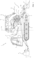
- a tracked vehicle in particular a snow groomer vehicle for the preparation of ski runs, according to one embodiment of the present invention is indicated as a whole with the number 1.
- the tracked vehicle 1 comprises a frame 2, which extends along a longitudinal axis D, a driver's cab 3, and a drive unit 5, for example an internal combustion engine or an electric motor.
- the driver's cab 3 and the drive unit 5 are housed on the frame 2.
- the tracked vehicle 1 is also provided with a pair of tracks 6 and with accessory devices 7.
- the accessory devices 7 comprise a blade or shovel 8, supported by the frame 2 at the front; and a tiller assembly 9, supported by the frame 2 at the rear.
- the tiller assembly 9 comprises a tiller and a finisher.
- the tiller assembly 9 can comprise auxiliary tillers (not shown in the figure) and track-setting assemblies (not shown in the figure) for setting tracks for cross-country ski runs.
- the accessory devices 7 comprise a winch assembly 10.
- a power transmission 12 ( Figure 3 ) is operatively coupled to the drive unit 5, which provides the power necessary for the operation of the tracked vehicle 1, and to the accessory devices 7.
- the power transmission 12 can be hydraulic or electric or a combination of both.
- the accessory devices 7 can also be called accessories.
- a tracked vehicle 1 does not necessarily comprise all the accessory devices 7 illustrated above.
- a tracked vehicle 1 can comprise any one or two of the accessory devices 7 selected from the blade 8, the tiller assembly 9 and the winch assembly 10.
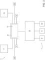
- a user interface 11 is installed in the driver's cab 3, which interface 11 allows an operator to control the movement of the tracked vehicle 1 and the operation of the accessory devices 7.
- the user interface 11 comprises a control device 4, a joystick 13 and a display 30.
- the control device 4 is configured to control the tracks 6.
- the control device 4 is coupled to the plurality of tracks 6 to control the movement of the tracked vehicle 1.
- the joystick 13 is coupled to the accessory devices 7 to control the movements of the accessory devices 7.
- the tracked vehicle 1 is provided with a control system 15.
- the control system 15 detects operating parameters of the tracked vehicle 1, such as, for example, but not limited to, the power delivered by the drive unit 5, the power absorbed by each of the accessory devices 7, the position of the blade 8 and of the tiller assembly 9, the position of the winch assembly 10, the drive speed of the tracked vehicle 1, and controls the drive unit 5, the tracks 6 and the accessory devices 7 based on the commands it receives from the user interface 11.
- operating parameters of the tracked vehicle such as, for example, but not limited to, the power delivered by the drive unit 5, the power absorbed by each of the accessory devices 7, the position of the blade 8 and of the tiller assembly 9, the position of the winch assembly 10, the drive speed of the tracked vehicle 1, and controls the drive unit 5, the tracks 6 and the accessory devices 7 based on the commands it receives from the user interface 11.
- the blade 8 can be raised or lowered. Moreover, the blade 8 can be rotated preferably by lateral inclination or by a roll motion, in practice creating a difference in height between the right and left ends of the blade 8 with respect to the plane of the tracks 6.
- the blade 8 can be tilted downwards to create a pitch motion in order to define an angle of incidence of the blade 8, also called the cutting angle.
- the blade 8 can be positioned perpendicularly or obliquely with respect to the direction of movement of the tracked vehicle 1, i.e., inclined or moved to define a yaw rotation.
- the joystick 13 of the user interface 11 is configured to control the blade 8.
- the joystick 13 is housed in the cab 3 and allows the above-described pitch, roll and yaw movements of the blade 8 to be controlled.
- the tiller assembly 9 is connected to the frame 2 of the tracked vehicle 1 so that it can be rotated, in practice by arranging the blade 8 perpendicular or oblique with respect to the direction of movement of the tracked vehicle 1, raised or lowered, and translated sideways. Furthermore, a relative angular position of the tiller assembly 9 can be determined with respect to the frame 2 in order to define a cutting angle of the tiller assembly 9.
- the joystick 13 of the user interface 11 is configured to control the tiller assembly 9 and allows the above-described movements of the tiller assembly 9 to be controlled.
- the winch assembly 10 comprises a drum 17, around which a rope 18 is wound, and an arm 19.
- the drum 17 rotates around an axis A and is driven by a motor and defines the pulling force of the rope 18.
- the arm 19 rotates around an axis B and is driven by an actuator to define the position of the arm 19 so as to orient the rope 18.
- the joystick 13 of the user interface 11 is configured to control the winch assembly 10, in particular the pulling force of the rope 18 and the angular position of the arm 19.
- the user interface 11 comprises the display 30 and a device 31 for detecting at least one touch on the display 30, to detect at least one touch of an operator U on the display 30 so as to detect selections made by an operator U by means of at least one touch on the display 30.
- the display 30, thanks to the detection device 31, is of the touch screen or touch-sensitive type and the control unit 15 is configured to receive selections by means of touches on the display 30.
- the control system 15 is coupled to the user interface 11, in particular to the display 30, and is configured for sending images to be displayed to the display 30 and receiving commands from the display 30 which are related to the touches detected, in order to detect selections made by the operator U of the tracked vehicle, typically a driver of the tracked vehicle.
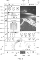
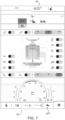
- control unit 11 is configured to display on the display 30 a main screen SM divided into a plurality of main screen portions PS1-PS8; wherein each main screen portion PS1-PS8 is configured to display an image that illustrates one or more pieces of data and/or information correlated to the tracked vehicle 1. Furthermore, commands can be set for the tracked vehicle 1 through at least some of the plurality of main screen portions PS1-PS8.
- the control unit 11 is configured to detect, in particular by means of the detection device 31, one or more touches on the display 30 relating to one or more selections made by an operator U on the display 30, corresponding to the type(s) of data or information that are required to be displayed in each portion of the display 30, and to display a related main screen portion PS1-PS8 in each related portion of the display 30, wherein the main screen portion PS1-PS8 is configured to illustrate a respective image relating to the data or information selected by the operator U.
- control unit 11 is configured to display in a first main screen portion PS1 of the plurality of main screen portions a first, preferably schematic depiction of the tracked vehicle 1.
- control unit 11 is configured to display in a second main screen portion PS2 of the plurality of main screen portions a second depiction of the tracked vehicle 1.
- first depiction is a top view of the tracked vehicle 1 and the second depiction is a side view of the tracked vehicle 1, and preferably the first and second depictions are schematic.
- each depiction of the tracked vehicle 1 shows, through said depiction, the accessories 7 the tracked vehicle 1 has at that moment.
- the shovel is also schematically represented in the first and/or second depiction.
- control unit 11 is configured to display in a third main screen portion PS3 of the plurality of main screen portions the data relating to the drive speed of the tracked vehicle and/or the data relating to the engine revolutions of the tracked vehicle and/or the data relating to a control light of the drive unit 5 and/or to the total working hours in the service life of the tracked vehicle and/or to the total distance travelled in the service life of the tracked vehicle and/or to the temperature of the fluid that is functional to the operation of the tracked vehicle, e.g., a temperature of a liquid in the drive unit 5, and/or to the residual power level(s) of the drive unit 5 in an energy harvesting system, e.g.
- the residual fuel level in a tank when the drive unit 5 is an internal combustion engine or the residual electrical energy level in a battery when the drive unit 5 is an electric motor, or the fuel and electrical energy levels when the drive unit 5 is hybrid and comprises a combustion engine as well as an electric motor.
- control unit 11 is configured to display in a fourth main screen portion PS4 of the plurality of main screen portions the data relating to the tilt of the tracked vehicle 1 according to a longitudinal axis, in particular to display the angle of roll of the tracked vehicle 1 around a roll axis; and/or the data relating to the tilt of the tracked vehicle 1 according to a transverse axis, in particular to display the pitch angle around a pitch axis.
- the tracked vehicle 1 comprises a tracking device 40, in particular a GPS receiver or the like, configured to establish the position of the tracked vehicle 1 and preferably comprising a memory with a plurality of maps, in particular maps of ski resorts for tracking the position of the tracked vehicle 1 in one of the ski resorts.
- a tracking device 40 in particular a GPS receiver or the like, configured to establish the position of the tracked vehicle 1 and preferably comprising a memory with a plurality of maps, in particular maps of ski resorts for tracking the position of the tracked vehicle 1 in one of the ski resorts.
- control unit 15 is configured to display in a fifth main screen portion PS5 of the plurality of main screen portions a navigation map of the tracked vehicle 1, preferably the control unit 15 is configured to display on the navigation map of the tracked vehicle 1 the path already travelled by the tracked vehicle 1.
- control unit 15 is configured to connect to a remote fleet management system and display on the map other tracked vehicles 1 present in the ski resort, and preferably display the path already travelled by the other tracked vehicles within the ski resort.
- the tracked vehicle 1 comprises at least one video camera 50 fixed at the rear of the tracked vehicle 1, preferably the position where the video camera 50 is fixed is at a point along a line parallel to the axis D and, with respect to the direction of travel, in the same position as or behind the drive wheels of the tracked vehicle 1 and/or the position of the winch 10.
- the video camera 50 is fixed above the tiller 9.
- the video camera 50 faces the rear of the tracked vehicle 1, in particular it is configured to frame a snow cover beyond the tiller 9 and/or the tracks 6.
- control unit 11 is configured to display in a sixth main screen portion of the plurality of main screen portions the images captured by the video camera 50 preferably framing the rear portion of the tracked vehicle 1, in particular a portion of snow already worked.
- control unit 15 is configured to display in the fifth portion PS5 or in the sixth portion PS6 of the main screen a thermostat for setting the temperature inside the cab of the tracked vehicle 1, instead of the map or the video camera image 50, respectively.
- control unit 15 is configured to display in the fifth portion PS5 or in the sixth portion PS6 of the main screen a frequency tuning for the stations of a car radio, instead of the map or the video camera image 50, respectively.
- control unit 15 is configured to detect, by means of touches of the operator U on the display 30, the selection of what to display in the main screen portions, in particular in the fifth PS5 and/or in the sixth PS6 screen portion the control unit 15 is configured to detect from the operator U whether to display the thermostat or the map or the frequency tuning or the video camera image.
- the accessory 7 comprises at least the winch 10, in this embodiment the control unit 15 is configured to display in a seventh portion PS7 of the main screen values relating to the winch, preferably one or more of the following values: length of cable unwound, pulling force in absolute value or as a percentage of the total possible pulling force.
- the accessory 7 comprises at least the tiller 9,
- the control unit 15 is configured to display in an eighth portion PS8 of the main screen a representation of a tiller 9, and preferably of any track-setting devices connected thereto, and preferably to illustrate next to the representation of the tiller 9 values relating to the tiller 9, preferably one or more of the following values: shaft rotation speed, shaft rotation direction, tilt angle of the tiller 9 with respect to the snow cover, percentage of snow recirculation inside a working chamber of the tiller 9.
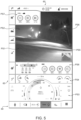
- control unit 15 is configured to work in a further display mode in which it is configured to display on the display 30 the image captured by the video camera 50 in the first PS1, the second PS2, the fifth PS5 and the sixth portion PS6 of the main screen SM, in particular different portions of the whole image are illustrated in a respective portion so that the whole image is illustrated among the various portions indicated above.
- the image relates to the frame captured by the video camera 50 facing the rear of the tracked vehicle 1, in particular it frames a portion of snow already worked.
- control unit 15 is configured to display in the first PS1, the second PS2, the fifth PS5 and the sixth portion PS6 of the main screen SM the image captured by the video camera 50 and, superimposed on a portion thereof, a miniature portion of the navigation map of the tracked vehicle 1, preferably the navigation map of the tracked vehicle 1 highlights the path already travelled by the tracked vehicle 1.
- control unit 15 is configured to display in the seventh portion PS7 of the main screen SM the data from the winch 10 as illustrated for Figures 3 and 4 , or a portion of the image captured by the video camera 50 and, in transparency, the data from the winch 10 superimposed on said image.
- control unit 15 is configured to work in a further display mode in which it is configured to display on the display 30 the navigation map of the tracked vehicle 1 in the first PS1, the second PS2, the fifth PS5 and the sixth portion PS6 of the main screen SM, preferably the navigation map of the tracked vehicle 1 highlights the path already travelled by the tracked vehicle 1 and preferably, in a small miniaturised portion, the image captured by a video camera 50 preferably framing the rear portion of the tracked vehicle 1, in particular a portion of snow already worked.
- control unit 15 is configured to display in the seventh portion PS7 of the main screen the data from the winch as illustrated for Figures 3 and 4 , or a portion of the map and, in transparency, the data from the winch 10 superimposed on said portion of the map.
- control unit 15 is configured to store the different configurations of the display 30, in particular the different configurations of the main screens SM, selected by different operators U and associate therewith a respective operator code, and is configured to call up and display on the display 30 one of the stored configurations when the operator code associated with one of the stored configurations is entered.
- control unit 15 is configured to receive signals from the accessories 7 connected to the tracked vehicle 1 and is configured to display in the representation of the tracked vehicle only the accessories 7 which are currently connected to the tracked vehicle 1, preferably one or more of the shovel, the tiller, the track setting devices and the winch. Accordingly, in the event that the tracked vehicle 1 does not have the winch 10 as an accessory 7, the control unit 15 will not illustrate the data from the winch 10 in the seventh portion PS7 of the main screen, and this portion of the screen will illustrate no information or information selected by an operator U, or the control unit 15 will display the information that was illustrated in the second portion PS2 of the main screen SM in Figure 3 or 4 , in the second portion PS2 of the main screen and in the seventh portion PS7 of the main screen. Similarly, in the event that the accessories 7 do not include a tiller 9, the control unit 15 is configured to display no information in the eighth portion PS8 of the main screen or it will illustrate other information selected by the user U.
- control unit 15 is configured to display in the representation of the tracked vehicle 1, the representation of the tensioning of the tracks 6 of the tracked vehicle 1, in particular by means of arrows positioned under the representation of the tracks 6 of the tracked vehicle 1 and indicating the directions associated with a tensioning of the tracks 6.
- said representation of the accessories 7 comprises the depiction of the current position of the accessories 7, in particular the raised or lowered position of the tiller 9 and/or the position, for example front or rear, of the arm 19 of the winch 10.
- the shovel 8 of the tracked vehicle 1 comprises a central blade and two side blades coupled to the central blade and configured to vary their position with respect to the central blade
- the control unit 15 is configured to receive signals from the shovel 8 and display in the representation of the tracked vehicle 1 the shovel assembly 8 with the central blade and the side blades and the current position of the side blades.
- the tiller 9 of the tracked vehicle 1 comprises two side wings (flaps) configured to vary their position with respect to a central body of the tiller 9, in particular to the rotating shaft of the tiller 9.
- the control unit 15 is configured to display in the representation of the tracked vehicle 1 the current position of the side wings of the tiller 9.
- control unit 15 is configured to work in an alternative display mode wherein the display of one or more of any of the images described above can be extended to two or more main screen portions, and one or more of any of the other images described above can be displayed in transparency over the one or more of any of the images that are extended to two or more screen portions.
- control unit 15 is configured to work in a further alternative display mode in which it is configured to display on the display 30 a secondary screen alternative to the main screen and depicting the internal operating parameters of the tracked vehicle 1.
- the internal operating parameters are configuration parameters for any device of the tracked vehicle 1, for example the switching on of one of the plurality of lighting devices arranged along the tracked vehicle 1 to illuminate the surrounding work environment or, for example, internal configuration parameters for the drive unit 5 and/or the tiller 9 and/or the winch 10 and/or the tracks 6 and/or a hydraulic system of the tracked vehicle 1, for example, the hydraulic system for feeding the tracks 6 and/or the winch 10 and/or the shovel 8 and/or the tiller 9.
- FIG. 7 An example of such a secondary screen is shown in Figure 7 in which, after a selection made by the operator U, the main screen is temporarily replaced by the secondary screen which illustrates the profile of the plurality of devices for lighting the surrounding environment and also allows the setting of configuration profiles for the plurality of lighting devices.
- control unit 15 is configured to display the main screen SM while the tracked vehicle 1 is moving, and the secondary screen following a selection made by the operator U and preferably when the tracked vehicle 1 is stationary.
- some secondary screens and consequently some parameters of the tracked vehicle 1 can only be displayed by authorized operators, such as maintenance technicians, and accessed via a maintenance code.
- the main screen SM displayed on the display 30 by the control unit 15 comprises a further plurality of screen portions QP1-QP13, preferably arranged along at least one of the outer edges 60 of the main screen SM, preferably along three outer edges 60 of the main screen SM.
- the control unit 15 is configured to couple each of the further plurality of screen portions QP1-QP13 to a respective plurality of secondary screens.
- the plurality of secondary screens illustrates further pluralities of parameters of the tracked vehicle 1, wherein at least one of the further pluralities of parameters is not shown in the main screen SM.
- the control unit 15 is configured to display one or more of the following further pluralities of screens: a first further screen portion QP1 depicting a schematised symbol of the winch, a second further screen portion QP2 depicting a schematised symbol of the tracked vehicle, preferably a snow groomer; a third further screen portion QP3 depicting a schematised symbol of the shovel, a fourth further screen portion QP4 depicting a schematised symbol of the cab; a fifth further screen portion QP5 depicting a schematised symbol of a shaft of the tiller; a sixth further screen portion QP6 depicting a schematised symbol of the tiller; a seventh further screen portion QP7 depicting a symbol of the lights; an eighth further screen portion QP8 depicting a symbol of a fan and of the temperature degrees; a ninth further screen portion QP9 depicting a symbol of a radio tuning and the name of a radio station; a tenth further screen portion QP10 depict
- the control unit 15 is configured to display on the display 30 the secondary screen associated with the respective further screen portion QP1-QP13 when it detects the touch of an operator U in an area occupied by one of the further screen portions QP1-QP13.
- Figure 7 depicts the secondary screen associated with the seventh further screen portion QP7.
- the control unit 15 detects the touch of the operator U, preferably through the detection device 31, and displays the secondary screen associated with the seventh further screen portion QP7, which is shown by way of example in Figure 7 and relates to a configuration profile for the lights that illuminate the external environment.
- the secondary screens accessible through the further screen portions QP1-QP13 illustrate parameters of the tracked vehicle 1 and allow the setting of parameters of the tracked vehicle 1, wherein at least some of said parameters of the secondary screens are not shown or cannot be set in the main screen SM.
- the first further screen portion QP1 depicting a schematised symbol of the winch 10 is associated with a secondary screen illustrating an additional plurality of parameters of the winch 10, both for configuration and for detection, wherein at least some of said parameters are not shown or cannot be configured in the main screen SM.
- the second further screen portion QP2 depicting a schematised symbol of the tracked vehicle 1, preferably a snow groomer, is associated with one or more secondary screens, wherein a first secondary screen illustrates parameters relating to the tensioning of the tracks 6 and wherein this first secondary screen allows the setting of parameters relating to the tensioning, in greater detail the tracked vehicle 1 comprises a tensioning device which is configured to adjust the tensioning of the tracks 6, said tensioning device is coupled to the control unit 15 and is adjustable through said first secondary screen; a second secondary screen illustrates parameters relating to the sensitivity of the driving commands, for example the sensitivity of a driving pedal of the tracked vehicle, of control levers coupled to the tracks of the tracked vehicle, of an autobrake system, and of the control of the suspensions, and allows the setting of said parameters; a third secondary screen illustrates parameters of the drive unit 5, for example, the number of engine revolutions, the operating mode of an air filter of the drive unit, and allows the setting of said parameters.
- a first secondary screen illustrates parameters relating to the tensioning of the
- the fourth further screen portion QP4 depicting a tracked vehicle, is associated with a secondary screen illustrating an additional plurality of parameters of the cab, both for configuration and for detection, wherein at least some of said parameters are not shown or cannot be configured in the main screen SM.
- the fifth further screen portion QP5 depicting a schematised symbol of the tiller 9 is associated with a secondary screen illustrating an additional plurality of parameters of the tiller 9, both for configuration and for detection, wherein at least some of said parameters are not shown or cannot be configured in the main screen SM.
- the eighth further screen portion QP8 depicting the symbol of a fan and of the temperature degrees is associated with a secondary screen illustrating an additional plurality of parameters of the fan and/or temperature, both for configuration and for detection, wherein at least some of said parameters are not shown or cannot be configured in the main screen SM.
- the ninth further screen portion QP9 depicting a symbol of a radio tuning and the name of a radio station is associated with a secondary screen illustrating an additional plurality of parameters of the radio station, both for configuration and for detection, wherein at least some of said parameters are not shown or cannot be configured in the main screen SM.
- the tenth further screen portion QP10 depicting a generic symbol, preferably, but not limited to, parallel lines, is associated with a secondary screen which, in turn, depicts a plurality of further secondary screens which can be selected by touching the display, and wherein at least some of these cannot be directly selected from the main screen.
- the eleventh further screen portion QP11 schematically depicting the symbol of a man and the name of an operator U is associated with a secondary screen in which an operator code can be entered to call up configurations of the main screen SM and/or of the secondary screens associated with said operator profile.
- the twelfth screen portion QP12 schematically depicting a clock and the date is associated with a secondary screen in which the time and date can be set.
- the thirteenth further screen portion QP13 depicting the outside temperature and symbols indicating the data communication signal reception values is associated with a secondary screen comprising more data relating to the outside temperature and the data communication reception.
- the display 30 is not of the touch screen type and the detection device 31 is omitted and replaced by a selector, which can be a knob or a wheel or a joystick or a set of the above devices to detect selections made by an operator.
- a selector which can be a knob or a wheel or a joystick or a set of the above devices to detect selections made by an operator.
Landscapes
- Engineering & Computer Science (AREA)
- Mechanical Engineering (AREA)
- Combustion & Propulsion (AREA)
- Transportation (AREA)
- Chemical & Material Sciences (AREA)
- Theoretical Computer Science (AREA)
- Architecture (AREA)
- Civil Engineering (AREA)
- Structural Engineering (AREA)
- General Engineering & Computer Science (AREA)
- General Physics & Mathematics (AREA)
- Physics & Mathematics (AREA)
- Human Computer Interaction (AREA)
- Multimedia (AREA)
- Component Parts Of Construction Machinery (AREA)
- Closed-Circuit Television Systems (AREA)
- Fittings On The Vehicle Exterior For Carrying Loads, And Devices For Holding Or Mounting Articles (AREA)
- Instrument Panels (AREA)
Applications Claiming Priority (3)
| Application Number | Priority Date | Filing Date | Title |
|---|---|---|---|
| IT102019000025747A IT201900025747A1 (it) | 2019-12-30 | 2019-12-30 | Veicolo cingolato comprendente un'interfaccia utente |
| EP20830352.9A EP4084983B1 (de) | 2019-12-30 | 2020-12-30 | Kettenfahrzeug mit benutzerschnittstelle |
| PCT/IB2020/062550 WO2021137175A1 (en) | 2019-12-30 | 2020-12-30 | Tracked vehicle comprising a user interface |
Related Parent Applications (2)
| Application Number | Title | Priority Date | Filing Date |
|---|---|---|---|
| EP20830352.9A Division EP4084983B1 (de) | 2019-12-30 | 2020-12-30 | Kettenfahrzeug mit benutzerschnittstelle |
| EP20830352.9A Division-Into EP4084983B1 (de) | 2019-12-30 | 2020-12-30 | Kettenfahrzeug mit benutzerschnittstelle |
Publications (2)
| Publication Number | Publication Date |
|---|---|
| EP4512702A2 true EP4512702A2 (de) | 2025-02-26 |
| EP4512702A3 EP4512702A3 (de) | 2025-05-07 |
Family
ID=70228629
Family Applications (2)
| Application Number | Title | Priority Date | Filing Date |
|---|---|---|---|
| EP24222857.5A Pending EP4512702A3 (de) | 2019-12-30 | 2020-12-30 | Kettenfahrzeug mit einer benutzerschnittstelle |
| EP20830352.9A Active EP4084983B1 (de) | 2019-12-30 | 2020-12-30 | Kettenfahrzeug mit benutzerschnittstelle |
Family Applications After (1)
| Application Number | Title | Priority Date | Filing Date |
|---|---|---|---|
| EP20830352.9A Active EP4084983B1 (de) | 2019-12-30 | 2020-12-30 | Kettenfahrzeug mit benutzerschnittstelle |
Country Status (6)
| Country | Link |
|---|---|
| US (1) | US12257899B2 (de) |
| EP (2) | EP4512702A3 (de) |
| CN (1) | CN113123287B (de) |
| CA (1) | CA3166052A1 (de) |
| IT (1) | IT201900025747A1 (de) |
| WO (1) | WO2021137175A1 (de) |
Families Citing this family (4)
| Publication number | Priority date | Publication date | Assignee | Title |
|---|---|---|---|---|
| USD983219S1 (en) | 2019-12-11 | 2023-04-11 | Prinoth S.P.A. | Display screen or a portion thereof with a graphical user interface |
| WO2022210662A1 (ja) * | 2021-03-31 | 2022-10-06 | 住友建機株式会社 | ショベル及びショベル用表示装置 |
| CN113733909B (zh) * | 2021-08-27 | 2023-06-23 | 三一汽车制造有限公司 | 车辆和车辆的控制方法 |
| FR3147023A1 (fr) * | 2023-03-22 | 2024-09-27 | Psa Automobiles Sa | Procédé et dispositif de contrôle d’une interface utilisateur d’un véhicule |
Family Cites Families (15)
| Publication number | Priority date | Publication date | Assignee | Title |
|---|---|---|---|---|
| DE2514874B2 (de) * | 1975-04-05 | 1978-08-17 | Zimmer Ag, 6000 Frankfurt | Verfahren zum Schnellspinnen von Polyamiden |
| US20020156574A1 (en) * | 2000-01-28 | 2002-10-24 | Manon Fortin | Snow groomer having improved electronic controls |
| US8413271B2 (en) * | 2004-10-29 | 2013-04-09 | Stryker Corporation | Patient support apparatus |
| US9440506B2 (en) * | 2006-10-30 | 2016-09-13 | Air Lift Company | Modular control system |
| DE102011007622A1 (de) * | 2011-04-18 | 2012-10-18 | Kässbohrer Geländefahrzeug AG | Pistenpflegefahrzeug |
| WO2012143043A1 (en) * | 2011-04-19 | 2012-10-26 | Abb Research Ltd | Method and system for controlling an industrial system |
| US9007318B2 (en) * | 2013-02-01 | 2015-04-14 | GM Global Technology Operations LLC | Method and apparatus for providing information related to an in-vehicle function |
| US9575628B2 (en) * | 2013-03-29 | 2017-02-21 | Deere & Company | Icon featured touch screen display system including status shortcuts for a work vehicle and method of managing the same |
| EP2930049B1 (de) * | 2014-04-08 | 2017-12-06 | Volkswagen Aktiengesellschaft | Anwenderschnittstelle und Verfahren zur Anpassung einer Ansicht auf einer Anzeigeeinheit |
| KR102400899B1 (ko) * | 2015-07-15 | 2022-05-23 | 엘지전자 주식회사 | 차량 제어 장치 및 그 방법 |
| WO2019028501A1 (en) * | 2017-08-07 | 2019-02-14 | Arb Corporation Ltd | SYSTEM AND METHOD FOR CONTROLLING THE OPERATION OF ONE OR MORE ACCESSORIES FOR A VEHICLE |
| US11086315B2 (en) * | 2017-10-26 | 2021-08-10 | 2KR Systems, LLC | Building rooftop intelligence gathering, decision-support and snow load removal system for protecting buildings from excessive snow load conditions, and automated methods for carrying out the same |
| DE102017127560A1 (de) * | 2017-11-22 | 2019-05-23 | Claas Selbstfahrende Erntemaschinen Gmbh | Bediensystem für eine landwirtschaftliche Arbeitsmaschine |
| AU2019346149A1 (en) * | 2018-09-27 | 2021-04-22 | SKADII GmbH | Ski resort management system |
| US11372527B2 (en) * | 2019-01-22 | 2022-06-28 | Ford Global Technologies, Llc | Dash cards user interface |
-
2019
- 2019-12-30 IT IT102019000025747A patent/IT201900025747A1/it unknown
-
2020
- 2020-12-30 EP EP24222857.5A patent/EP4512702A3/de active Pending
- 2020-12-30 CN CN202011608195.XA patent/CN113123287B/zh active Active
- 2020-12-30 WO PCT/IB2020/062550 patent/WO2021137175A1/en not_active Ceased
- 2020-12-30 EP EP20830352.9A patent/EP4084983B1/de active Active
- 2020-12-30 US US17/789,853 patent/US12257899B2/en active Active
- 2020-12-30 CA CA3166052A patent/CA3166052A1/en active Pending
Also Published As
| Publication number | Publication date |
|---|---|
| CN113123287A (zh) | 2021-07-16 |
| EP4084983A1 (de) | 2022-11-09 |
| WO2021137175A1 (en) | 2021-07-08 |
| US12257899B2 (en) | 2025-03-25 |
| CN113123287B (zh) | 2025-12-02 |
| IT201900025747A1 (it) | 2021-06-30 |
| EP4084983C0 (de) | 2025-03-19 |
| EP4512702A3 (de) | 2025-05-07 |
| EP4084983B1 (de) | 2025-03-19 |
| CA3166052A1 (en) | 2021-07-08 |
| US20230036971A1 (en) | 2023-02-02 |
Similar Documents
| Publication | Publication Date | Title |
|---|---|---|
| EP4084983B1 (de) | Kettenfahrzeug mit benutzerschnittstelle | |
| EP2607210B1 (de) | Anhänger-Rückfahrhilfe unter Verwendung von GPS-Abbildung und Kamerabildanzeige | |
| US9322147B2 (en) | Information display device of construction machine, information display method of construction machine, and information display computer program of construction machine | |
| CN104598108B (zh) | 一种智能终端触控方式比例遥控被遥控设备的方法 | |
| EP3421316B1 (de) | Deaktivierung von bordeigenen eingabevorrichtungen in einem autonomen fahrzeug | |
| US20140031954A1 (en) | Operating unit for a construction machine and method for operating the operating unit | |
| DE102018133011B4 (de) | Fahrzeugfernsteuerungsvorrichtung und fahrzeugfernsteuerungsverfahren | |
| US9702121B2 (en) | State information display for work machine, caution-sign displaying method for work machine, and caution-sign displaying program for work machine | |
| US20240209591A1 (en) | Excavator, and excavator operation system | |
| KR101747274B1 (ko) | 휠식 작업 기계 | |
| US20230060917A1 (en) | Motor grader and representation control method | |
| US12578722B2 (en) | Operation assistance method, operation assistance system, and operation assistance program | |
| US20250251890A1 (en) | Remote control apparatus and remote manipulation system | |
| US20250075470A1 (en) | Work machine | |
| CA3049747A1 (en) | Tracked vehicle and fleet of tracked vehicles | |
| US20080258896A1 (en) | System for improving back end visibility and machine using same | |
| JP2021017194A (ja) | 操作部制御装置及び車両制御システム | |
| EP4707465A2 (de) | Schneegroomer und verfahren zur steuerung eines schneegroomers | |
| CN107472142A (zh) | 车辆安全驾驶辅助观察及互联网应用系统 | |
| WO2023280554A1 (de) | Teleoperator-arbeitsplatz | |
| JP7154997B2 (ja) | 走行支援装置、走行支援装置を備えた作業車両及び走行支援方法 | |
| JP2022152970A (ja) | ショベル、ショベルの管理システム | |
| JP7837858B2 (ja) | 遠隔装置および遠隔操縦システム | |
| US12575474B2 (en) | Automatic traveling method, automatic traveling system, and automatic traveling program | |
| US20240196775A1 (en) | Operation Control Method, Operation Control System, And Operation Control Program |
Legal Events
| Date | Code | Title | Description |
|---|---|---|---|
| PUAI | Public reference made under article 153(3) epc to a published international application that has entered the european phase |
Free format text: ORIGINAL CODE: 0009012 |
|
| STAA | Information on the status of an ep patent application or granted ep patent |
Free format text: STATUS: THE APPLICATION HAS BEEN PUBLISHED |
|
| AC | Divisional application: reference to earlier application |
Ref document number: 4084983 Country of ref document: EP Kind code of ref document: P |
|
| AK | Designated contracting states |
Kind code of ref document: A2 Designated state(s): AL AT BE BG CH CY CZ DE DK EE ES FI FR GB GR HR HU IE IS IT LI LT LU LV MC MK MT NL NO PL PT RO RS SE SI SK SM TR |
|
| REG | Reference to a national code |
Ref country code: DE Ref legal event code: R079 Free format text: PREVIOUS MAIN CLASS: B62D0055280000 Ipc: E01H0004000000 |
|
| PUAL | Search report despatched |
Free format text: ORIGINAL CODE: 0009013 |
|
| AK | Designated contracting states |
Kind code of ref document: A3 Designated state(s): AL AT BE BG CH CY CZ DE DK EE ES FI FR GB GR HR HU IE IS IT LI LT LU LV MC MK MT NL NO PL PT RO RS SE SI SK SM TR |
|
| RIC1 | Information provided on ipc code assigned before grant |
Ipc: B60K 35/81 20240101ALI20250401BHEP Ipc: E01H 4/02 20060101ALI20250401BHEP Ipc: B62D 55/28 20060101ALI20250401BHEP Ipc: B60K 35/28 20240101ALI20250401BHEP Ipc: B60K 35/22 20240101ALI20250401BHEP Ipc: B60K 35/10 20240101ALI20250401BHEP Ipc: B62D 55/00 20060101ALI20250401BHEP Ipc: E01H 4/00 20060101AFI20250401BHEP |
|
| STAA | Information on the status of an ep patent application or granted ep patent |
Free format text: STATUS: REQUEST FOR EXAMINATION WAS MADE |
|
| 17P | Request for examination filed |
Effective date: 20251107 |