EP4512694A1 - Lenksteuerungsvorrichtung und elektrische servolenkvorrichtung - Google Patents
Lenksteuerungsvorrichtung und elektrische servolenkvorrichtung Download PDFInfo
- Publication number
- EP4512694A1 EP4512694A1 EP22938550.5A EP22938550A EP4512694A1 EP 4512694 A1 EP4512694 A1 EP 4512694A1 EP 22938550 A EP22938550 A EP 22938550A EP 4512694 A1 EP4512694 A1 EP 4512694A1
- Authority
- EP
- European Patent Office
- Prior art keywords
- torque
- steering
- calculation unit
- steering angle
- map
- Prior art date
- Legal status (The legal status is an assumption and is not a legal conclusion. Google has not performed a legal analysis and makes no representation as to the accuracy of the status listed.)
- Pending
Links
Images


Classifications
-
- B—PERFORMING OPERATIONS; TRANSPORTING
- B62—LAND VEHICLES FOR TRAVELLING OTHERWISE THAN ON RAILS
- B62D—MOTOR VEHICLES; TRAILERS
- B62D5/00—Power-assisted or power-driven steering
- B62D5/04—Power-assisted or power-driven steering electrical, e.g. using an electric servo-motor connected to, or forming part of, the steering gear
- B62D5/0457—Power-assisted or power-driven steering electrical, e.g. using an electric servo-motor connected to, or forming part of, the steering gear characterised by control features of the drive means as such
- B62D5/046—Controlling the motor
- B62D5/0466—Controlling the motor for returning the steering wheel to neutral position
-
- B—PERFORMING OPERATIONS; TRANSPORTING
- B62—LAND VEHICLES FOR TRAVELLING OTHERWISE THAN ON RAILS
- B62D—MOTOR VEHICLES; TRAILERS
- B62D5/00—Power-assisted or power-driven steering
- B62D5/04—Power-assisted or power-driven steering electrical, e.g. using an electric servo-motor connected to, or forming part of, the steering gear
- B62D5/0457—Power-assisted or power-driven steering electrical, e.g. using an electric servo-motor connected to, or forming part of, the steering gear characterised by control features of the drive means as such
- B62D5/046—Controlling the motor
- B62D5/0463—Controlling the motor calculating assisting torque from the motor based on driver input
-
- B—PERFORMING OPERATIONS; TRANSPORTING
- B62—LAND VEHICLES FOR TRAVELLING OTHERWISE THAN ON RAILS
- B62D—MOTOR VEHICLES; TRAILERS
- B62D6/00—Arrangements for automatically controlling steering depending on driving conditions sensed and responded to, e.g. control circuits
- B62D6/008—Control of feed-back to the steering input member, e.g. simulating road feel in steer-by-wire applications
Definitions
- the present disclosure relates to a steering control device and an electric power steering device.
- An electric power steering device includes a motor that generates a steering assist torque for steering, and a steering control device that controls the motor, and adds a steering assist force to a steering mechanism of a vehicle such as an automobile.
- Such an electric power steering device has an advantage of being lighter and more compact compared to a hydraulic power steering device.
- Patent Document 1 discloses an electric power steering device that is not affected by a change in mechanism characteristics due to road surface conditions or deterioration with age of a steering mechanism and can obtain a constant steering feeling.
- this electric power steering device by setting a characteristic of a steering force relative to a steering angle (hereinafter, referred to as a "steering force-angle characteristic") to be a desired steering force characteristic (target steering force-angle characteristic), a constant steering feeling is obtained.
- a steering force-angle characteristic a characteristic of a steering force relative to a steering angle
- Patent Document 1 Japanese Patent No. 6129409
- a target steering force is calculated using a steering force characteristics model including a spring component, a viscosity component, and a friction component.
- a steering force characteristics model including a spring component, a viscosity component, and a friction component.
- the present disclosure has been made in view of the above circumstances, and an object of the present disclosure is to provide a steering control device and an electric power steering device capable of adjusting an on-center feeling with a simple configuration while suppressing an influence on a steering feeling that has already been set.
- a steering control device includes: a target steering torque setting unit configured to set a target steering torque for steering; a calculation unit configured to calculate, based on a deviation between the target steering torque and a steering torque acting on a steering shaft of the steering, a steering assist torque necessary for causing the steering torque to follow the target steering torque; and a current drive unit configured to control a current flowing to a motor to generate the steering assist torque for the steering, in which the target steering torque setting unit includes a first torque calculation unit configured to calculate a first shift amount, which is a shift amount of a steering angle of a steering wheel, by multiplying a rotation angular velocity of the motor by a steering angle gain, and to obtain a first torque based on a post-shift steering angle obtained by adding the first shift amount to the steering angle and a base map showing a characteristic of gradually increasing a magnitude of a base torque as a magnitude of the post-shift steering angle increases, a second torque calculation unit configured to obtain a second
- a power steering device includes: a steering torque detection unit configured to detect a steering torque acting on a steering shaft of steering; a steering state detection unit configured to detect a steering angle of a steering wheel; a motor configured to apply a steering assist torque to the steering shaft; a motor rotation angular velocity detection unit configured to detect a rotation angular velocity of the motor; and the above-described steering control device configured to control drive of the motor based on the detected steering torque, the detected steering angle, and the detected rotation angular velocity of the motor.
- an on-center feeling can be adjusted with a simple configuration while suppressing an influence on a steering feeling that has been already set.
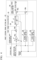
- FIG. 1 is a block diagram showing a configuration of a main part of an electric power steering device according to a first embodiment of the present disclosure.
- an electric power steering device PS according to the present embodiment includes a steering wheel 1, a steering shaft 2, turning wheels 3, a steering angle sensor 4, a torque sensor 5 (steering torque detection unit), a motor 6, a reduction gear 7, a vehicle speed sensor 8, a current sensor 9, a motor rotation angle sensor 10, and a control unit 11 (steering control device).
- the steering wheel 1 is a so-called handle, and is operated by a driver of a vehicle in order to provide a steering angle for the turning wheels 3 of the vehicle.
- the steering shaft 2 is connected to the steering wheel 1 and is rotated in response to the rotation of the steering wheel 1.
- the turning wheels 3 are provided on both left and right sides of the vehicle and are turned in response to the rotation of the steering shaft 2. It should be noted that a mechanism that includes the steering wheel 1 and the steering shaft 2 to turn the turning wheels 3 will be referred to as "steering".
- the steering angle sensor 4 is disposed in the steering wheel 1 and detects a steering angle of the steering wheel 1.
- the torque sensor 5 is disposed on the steering shaft 2 and detects a steering torque acting on the steering shaft 2.
- the motor 6 is connected to the steering shaft 2 via the reduction gear 7, and applies a steering assist torque to the steering shaft 2.
- the vehicle speed sensor 8 detects a vehicle speed of the vehicle.
- the current sensor 9 detects a current flowing through the motor 6.
- the motor rotation angle sensor 10 detects a rotation angle of the motor 6.
- the control unit 11 controls driving of the motor 6 based on detection results of the steering angle sensor 4, the torque sensor 5, the vehicle speed sensor 8, the current sensor 9, and the motor rotation angle sensor 10 to generate the steering assist torque for the steering. Specifically, the control unit 11 calculates the steering assist torque to be provided to the steering shaft 2 based on each of the above-described detection results and controls the current of the motor 6 necessary for generating the steering assist torque.
- the control unit 11 will be described in detail.
- FIG. 2 is a block diagram showing a configuration of a main part of the control unit as the steering control device according to the first embodiment of the present disclosure.
- the control unit 11 includes a differentiator 24a, a target steering torque setting unit 22, a torque feedback calculation unit 23 (calculation unit), and a current drive unit 12.
- the differentiator 24a differentiates the rotation angle of the motor 6 detected by the motor rotation angle sensor 10 to calculate a rotation angular velocity of the motor 6 (hereinafter, referred to as a "motor rotation angular velocity").
- the differentiator 24a and the motor rotation angle sensor 10 constitute a motor rotation angular velocity detection unit 24 that detects the motor rotation angular velocity.
- the target steering torque setting unit 22 sets a target steering torque for the steering.
- the target steering torque setting unit 22 receives, as inputs, the steering angle of the steering wheel 1 detected by a steering state detection unit 21 including the steering angle sensor 4, the vehicle speed of the vehicle detected by the vehicle speed sensor 8, and the motor rotation angular velocity detected by the motor rotation angular velocity detection unit 24.
- the target steering torque setting unit 22 sets the target steering torque for the steering by using these detection results. The details of the target steering torque setting unit 22 will be described later.
- a configuration excluding the current drive unit 12 (the differentiator 24a, the target steering torque setting unit 22, and the torque feedback calculation unit 23) is implemented by a microcomputer including a central processing unit (CPU) and a memory.
- the memory provided in the microcomputer may include both a volatile memory and a non-volatile memory.
- the current drive unit 12 is implemented by, for example, an analog circuit including a plurality of switching elements, such as a field-effect transistor (FET).
- FET field-effect transistor
- FIG. 3 is a flowchart showing an outline of an operation of the control unit as the steering control device according to the first embodiment of the present disclosure. It should be noted that processing of the flowchart shown in FIG. 3 is repeatedly performed in a predetermined control cycle. In a case where the processing is started, first, the control unit 11 acquires the steering angle detected by the steering state detection unit 21, the vehicle speed detected by the vehicle speed sensor 8, the steering torque detected by the torque sensor 5, and the motor rotation angle detected by the motor rotation angle sensor 10. Then, the differentiator 24a of the control unit 11 differentiates the acquired motor rotation angle to obtain the motor rotation angular velocity (step S11).
- the target steering torque setting unit 22 of the control unit 11 sets the target steering torque using the acquired steering angle and vehicle speed and the motor rotation angular velocity obtained by differentiation (step S12). Then, the torque feedback calculation unit 23 of the control unit 11 calculates the steering assist torque necessary for causing the steering torque to follow the target steering torque based on the deviation between the target steering torque set by the target steering torque setting unit 22 and the steering torque detected by the torque sensor 5 (step S13). Subsequently, the current drive unit 12 of the control unit 11 controls the current flowing to the motor 6 in order to generate the steering assist torque calculated by the torque feedback calculation unit 23 in the steering (step S16).
- FIG. 4 is a block diagram showing an example of an internal configuration of the target steering torque setting unit in the first embodiment of the present disclosure.
- the target steering torque setting unit 22 includes a first torque calculation unit 25, a second torque calculation unit 28, a third torque calculation unit 29, and a target steering torque calculation unit 30.
- the first torque calculation unit 25 includes a steering angle shift calculation unit 26 and a base calculation unit 27, and obtains a first torque, which is a base torque, using the steering angle, the motor rotation angular velocity, and the vehicle speed.
- the steering angle shift calculation unit 26 includes a multiplier 26a and an adder 26b to obtain a post-shift steering angle.
- the multiplier 26a calculates a first shift amount, which is a shift amount of the steering angle of the steering wheel 1, by multiplying the motor rotation angular velocity by a steering angle shift gain Dg (steering angle gain).
- the adder 26b adds the first shift amount to the steering angle to obtain the post-shift steering angle.
- the base calculation unit 27 obtains the first torque based on the post-shift steering angle obtained by the steering angle shift calculation unit 26 and a base map indicating a characteristic of gradually increasing a magnitude of the base torque as a magnitude of the post-shift steering angle increases.
- FIG. 5 is a diagram showing an example of the steering angle shift gain used in the first torque calculation unit in the first embodiment of the present disclosure.
- the steering angle shift gain Dg shown in FIG. 5 is a value that gradually increases as the vehicle speed increases up to a certain vehicle speed, but the value becomes constant beyond the certain vehicle speed. In a case where such a steering angle shift gain Dg is used, the steering angle shift gain Dg is changed according to the vehicle speed in the first torque calculation unit 25.
- the steering angle shift gain Dg shown in FIG. 5 is changed in value according to the vehicle speed, but may not be changed in value regardless of the vehicle speed.
- FIG. 6A is a block diagram showing a configuration example of the base calculation unit provided in the first torque calculation unit in the first embodiment of the present disclosure.
- the base calculation unit 27 shown in FIG. 6A includes a base map 27a, a sign determination unit 27b, and a multiplier 27c.
- the base map 27a is a map in which the base torque is defined according to the post-shift steering angle.
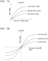
- FIG. 7A is a diagram showing an example of the base map used in the base calculation unit shown in FIG. 6A .
- the base map 27a shown in FIG. 7A has a characteristic of gradually increasing a magnitude of the base torque in a positive direction as the magnitude (absolute value) of the post-shift steering angle increases.
- the base map 27a is prepared to be different for each vehicle speed.
- different base maps 27a are prepared for each of "low vehicle speed", “medium vehicle speed”, and "high vehicle speed”.
- the base map 27a in the first torque calculation unit 25 is changed according to the vehicle speed.
- the base map 27a does not necessarily need to be prepared to be different for each vehicle speed.
- the sign determination unit 27b determines whether a sign of the post-shift steering angle is positive (+1) or negative (-1).
- the multiplier 27c multiplies the magnitude of the base torque obtained by using the base map 27a and the sign determined by the sign determination unit 27b.
- one base map 27a is specified according to the input vehicle speed.
- the magnitude of the base torque (first torque) is obtained by using the post-shift steering angle input to the base calculation unit 27 and the specified base map 27a.
- the sign of the input post-shift steering angle is determined by the sign determination unit 27b.
- the magnitude of the base torque (first torque) obtained by using the base map 27a and the sign of the post-steering angle determined by the sign determination unit 27b are multiplied by the multiplier 27c, whereby the base torque (first torque) is obtained.
- FIG. 6B is a block diagram showing another configuration example of the base calculation unit provided in the first torque calculation unit in the first embodiment of the present disclosure.
- the base calculation unit 27 shown in FIG. 6B includes only the base map 27a.
- the base map 27a shown in FIG. 6B is a map in which the base torque is defined according to the post-shift steering angle as in the base map 27a shown in FIG. 6A .
- FIG. 7B is a diagram showing an example of the base map used in the base calculation unit shown in FIG. 6B .
- the base map 27a shown in FIG. 6B has a characteristic of gradually increasing the magnitude of the base torque in the positive direction as the magnitude of the post-shift steering angle in the positive direction increases and gradually increasing the magnitude of the base torque in a negative direction as the magnitude of the post-shift steering angle in the negative direction increases, as shown in FIG. 7B .
- the base map 27a shown in FIG. 6B is also prepared to be different for each vehicle speed.
- different base maps 27a are prepared for each of "low vehicle speed", "medium vehicle speed", and "high vehicle speed”.
- the base map 27a in the first torque calculation unit 25 is changed according to the vehicle speed.
- the base map 27a does not necessarily need to be prepared to be different for each vehicle speed.
- one base map 27a is specified according to the input vehicle speed.
- the base torque (first torque) is obtained by using the post-shift steering angle input to the base calculation unit 27 and the specified base map 27a.
- the second torque calculation unit 28 obtains a second torque, which is a friction torque, based on the motor rotation angular velocity and the vehicle speed.
- a second torque which is a friction torque
- the second torque is represented by the following expression.
- the second torque (friction torque) has a constant magnitude and is saturated as the motor rotation angular velocity d ⁇ m increases.
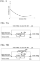
- FIG. 8 is a diagram showing an example of the hysteresis gain used in the second torque calculation unit in the first embodiment of the present disclosure.
- the hysteresis gain Tf shown in FIG. 8 is a value that gradually decreases as the vehicle speed increases up to a certain vehicle speed, but the value gradually increases as the vehicle speed increases beyond the certain vehicle speed.
- the hysteresis gain Tf shown in FIG. 8 is changed according to the vehicle speed, but may not be changed in value regardless of the vehicle speed.
- a low-pass filter process by a low-pass filter may be performed on the obtained second torque (friction torque).
- a cutoff frequency of the low-pass filter is set to a value that can extract a frequency component set to include a steering frequency of the driver.
- a limit steering frequency of the driver is about 5 [Hz]
- a resonant frequency of the steering shaft 2 is around several tens of [Hz]. Therefore, the cutoff frequency is set to a value greater than 0 and equal to or less than 10 [Hz].
- the third torque calculation unit 29 obtains a third torque, which is a damper torque, based on the motor rotation angular velocity and the vehicle speed.
- FIG. 9A is a block diagram showing a configuration example of the third torque calculation unit in the first embodiment of the present disclosure.
- the third torque calculation unit 29 shown in FIG. 9A includes a damper gain map 29a and a multiplier 29b.
- the damper gain map 29a is a map in which a damper gain is defined according to the motor rotation angular velocity.
- FIG. 10A is a diagram showing an example of the damper gain map used in the third torque calculation unit shown in FIG. 9A .
- the damper gain map 29a shown in FIG. 10A has a characteristic of gradually increasing a magnitude of the damper gain as a magnitude (absolute value) of the motor rotation angular velocity increases when the magnitude (absolute value) of the motor rotation angular velocity exceeds a certain value.
- the magnitude of the damper gain is zero until the magnitude (absolute value) of the motor rotation angular velocity reaches a certain value.
- the damper gain map 29a is prepared to be different for each vehicle speed.
- different damper gain maps 29a are prepared for each of "low vehicle speed”, “medium vehicle speed”, and "high vehicle speed”.
- the damper gain map 29a in the third torque calculation unit 29 is changed according to the vehicle speed.
- the damper gain map 29a does not necessarily need to be prepared to be different for each vehicle speed.
- the multiplier 29b multiplies the motor rotation angular velocity by the damper gain obtained by using the damper gain map 29a.
- one damper gain map 29a is specified according to the input vehicle speed.
- the damper gain is obtained by using the motor rotation angular velocity input to the third torque calculation unit 29 and the specified damper gain map 29a. Then, the damper gain obtained by using the damper gain map 29a and the motor rotation angular velocity are multiplied by the multiplier 29b, whereby the damper torque (third torque) is obtained.
- FIG. 9B is a block diagram showing another configuration example of the third torque calculation unit in the first embodiment of the present disclosure.
- the third torque calculation unit 29 shown in FIG. 9B includes a damper torque map 29c, a sign determination unit 29d, and a multiplier 29e.
- the damper torque map 29c is a map in which the damper torque is defined according to the motor rotation angular velocity.
- FIG. 10B is a diagram showing an example of the damper torque map used in the third torque calculation unit shown in FIG. 9B .
- the damper torque map 29c shown in FIG. 10B has the same characteristic as the damper gain map 29a shown in FIG. 10A . That is, the damper torque map 29c shown in FIG. 10B has a characteristic of gradually increasing a magnitude of the damper torque as the magnitude (absolute value) of the motor rotation angular velocity increases when the magnitude (absolute value) of the motor rotation angular velocity exceeds a certain value. The magnitude of the damper torque is zero until the magnitude (absolute value) of the motor rotation angular velocity reaches a certain value.
- the damper torque map 29c is prepared to be different for each vehicle speed.
- different damper torque maps 29c are prepared for each of "low vehicle speed", “medium vehicle speed”, and "high vehicle speed”.
- the damper torque map 29c in the third torque calculation unit 29 is changed according to the vehicle speed.
- the damper torque map 29c does not necessarily need to be prepared to be different for each vehicle speed.
- the sign determination unit 29d determines whether the sign of the motor rotation angular velocity is positive (+1) or negative (-1).
- the multiplier 29e multiplies the magnitude of the damper torque obtained by using the damper torque map 29c and the sign determined by the sign determination unit 29d.
- one damper torque map 29c is specified according to the input vehicle speed.
- the magnitude of the damper torque (third torque) is obtained by using the motor rotation angular velocity input to the third torque calculation unit 29 and the specified damper torque map 29c.
- the sign of the input motor rotation angular velocity is determined by the sign determination unit 29d.
- the magnitude of the damper torque (third torque) obtained by using the damper torque map 29c and the sign of the motor rotation angular velocity determined by the sign determination unit 29d are multiplied by the multiplier 29e, whereby the damper torque (third torque) is obtained.
- the target steering torque calculation unit 30 includes adders 30a and 30b, and adds the base torque (first torque) calculated by the first torque calculation unit 25, the friction torque (second torque) calculated by the second torque calculation unit 28, and the damper torque (third torque) calculated by the third torque calculation unit 29. Specifically, the friction torque (second torque) and the damper torque (third torque) are added by the adder 30b, and the torque output from the adder 30b and the base torque (first torque) are added by the adder 30a.
- the target steering torque calculation unit 30 outputs the torque obtained by addition as the target steering torque.
- FIG. 11 is a block diagram showing an example of an internal configuration of the torque feedback calculation unit in the first embodiment of the present disclosure.
- the torque feedback calculation unit 23 includes a subtractor 31, a first steering assist torque calculation unit 32, a second steering assist torque calculation unit 33, a third steering assist torque calculation unit 34, and an adder 35.
- the torque feedback calculation unit 23 calculates the steering assist torque necessary for causing the steering torque to follow the target steering torque based on the deviation between the target steering torque set by the target steering torque setting unit 22 and the steering torque detected by the torque sensor 5.
- the subtractor 31 obtains the deviation between the target steering torque set by the target steering torque setting unit 22 and the steering torque detected by the torque sensor 5.
- the first steering assist torque calculation unit 32 includes an integrator 32a and a multiplier 23b, and calculates a first steering assist torque by integrating the deviation obtained by the subtractor 31 by the integrator 32a and performing a calculation of multiplying the integrated deviation by an integral control gain KTI in the multiplier 32b.
- the second steering assist torque calculation unit 33 includes a multiplier 33a, and calculates a second steering assist torque by performing a calculation of multiplying the motor rotation angular velocity by a speed control gain KTV in the multiplier 33a.
- the third steering assist torque calculation unit 34 includes a multiplier 34a, and calculates a third steering assist torque by performing a calculation of multiplying the deviation obtained by the subtractor 31 by a proportional control gain KTP in the multiplier 34a.
- a steering assist torque proportional control component (third steering assist torque) has a faster response than the steering assist torque integral control component (first steering assist torque), which leads to a faster follow-up response and reduced overshoot.
- the steering torque stably follows the target steering torque, thereby achieving smoother steering.
- the torque feedback calculation unit 23 that performs torque feedback is provided has been described as an example.
- the configuration is not limited to the configuration in which the torque feedback is performed as long as the deviation between the target steering torque and the steering torque can be fed back.
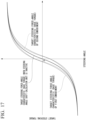
- a target steering force-angle characteristic C is a characteristic in the technology disclosed in Patent Document 1, in which the same on-center feeling characteristic as the target steering force-angle characteristic B is adjusted and imparted to the target steering force-angle characteristic A by a viscosity component.
- a target steering force-angle characteristic D is a characteristic in the technology disclosed in Patent Document 1, in which the same on-center feeling characteristic as the target steering force-angle characteristic B is adjusted and imparted to the target steering force-angle characteristic A by a friction component.
- the target steering force-angle characteristic is significantly changed from the initially set basic target steering force-angle characteristic A. Therefore, re-adaptation is required for all of the base torque, the damper torque, and the friction torque.
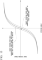
- FIG. 13 is a diagram showing a relationship between the steering angle and the target steering torque (base torque) when the steering wheel is steered in the first embodiment of the present disclosure.
- base torque target steering torque
- FIG. 13 in a case where the steering is performed with a sine wave as in the adaptation method, a peak of the motor rotation angular velocity appears near a neutral position. Therefore, as shown in FIG. 13 , in a case where the steering angle shift calculation unit 26 is active, a torque can be applied to be specialized for about a neutral point of the base torque (first torque), and thus the on-center feeling can be adjusted.
- the steering angle shift gain Dg of the steering angle shift calculation unit 26, the damper gain map 29a of the base calculation unit 27 that is used to obtain the first torque, the second torque calculation unit 28 that is used to obtain the second torque, and the damper gain map 29a of the third torque calculation unit 29 that is used to obtain the third torque are variable with respect to the vehicle speed. Accordingly, it is possible to set an appropriate control gain in response to characteristics of a road surface reaction torque that varies with the vehicle speed, and it is possible to flexibly set the target steering torque according to the vehicle speed, whereby it is possible to achieve a wide variety of steering feelings. It should be noted that all the gains do not need to be variable with respect to the vehicle speed, and at least one gain or map may be variable with respect to the vehicle speed.
- the steering angle sensor 4 is provided in the steering state detection unit 21, and the steering angle detected by the steering angle sensor 4 is used in the steering angle shift calculation unit 26.
- a steering angle into which the motor rotation angle detected by the motor rotation angle sensor 10 is converted may be used.
- an angle of the steering shaft 2 into which the motor rotation angle detected by the motor rotation angle sensor 10 is converted using a reduction ratio of the reduction gear 7 may be used.
- FIG. 15 is a block diagram showing the configuration of the steering angle shift calculation unit in the second embodiment of the present disclosure.
- a steering angle shift calculation unit 26 according to the present embodiment has a configuration in which a steering angle application range adjustment map 26c and a multiplier 26d are added to the steering angle shift calculation unit 26 shown in FIG. 4 .
- the steering angle shift calculation unit 26 shown in FIG. 4 and the steering angle shift calculation unit 26 in the present embodiment shown in FIG. 15 are different from each other in a method of calculating the first shift amount, which is the shift amount of the steering angle of the steering wheel 1.
- the steering angle application range adjustment map 26c is prepared to be different for each vehicle speed.
- different steering angle application range adjustment maps 26c are prepared for each of "low vehicle speed”, “medium vehicle speed”, and "high vehicle speed”.
- the steering angle application range adjustment map 26c in the first torque calculation unit 25 is changed according to the vehicle speed.
- the steering angle application range adjustment map 26c does not necessarily need to be prepared to be different for each vehicle speed.
- the multiplier 26d multiplies the first shift amount output from the multiplier 26a by the steering angle application range adjustment gain obtained by using the steering angle application range adjustment map 26c to calculate a second shift amount, which is the shift amount of the steering angle after steering angle application range adjustment.
- the steering angle shift gain Dg is specified according to the input vehicle speed, and the specified steering angle shift gain Dg and the motor rotation angular velocity are multiplied by the multiplier 26a to calculate the first shift amount (the shift amount of the steering angle of the steering wheel 1).
- one steering angle application range adjustment map 26c is specified according to the input vehicle speed, and the steering angle application range adjustment gain is obtained by using the input steering angle and the specified steering angle application range adjustment map 26c.
- the first shift amount and the steering angle application range adjustment gain are multiplied by the multiplier 26d to calculate the second shift amount (the shift amount of the steering angle after the steering angle application range adjustment).
- the post-shift steering angle is calculated by adding the second shift amount to the steering angle by the adder 26b.
- the present disclosure is not limited to the above-described embodiments, and may be freely modified without departing from the gist of the present disclosure.
- the electric power steering device PS described in the above-described embodiment may be of a column type or may be of a rack-and-pinion type.
- the feedback control based on the target steering torque can be applied to a steer-by-wire reaction force unit or the like including at least a torque sensor.
- the drawings used in the description of the above-described embodiments are exemplary examples, and the present disclosure is not limited thereto.
- each configuration (the target steering torque setting unit 22 and the torque feedback calculation unit 23) provided in the control unit 11 described above has an internal computer system.
- a program for implementing functions of each configuration provided by the control unit 11 described above may be recorded on a computer-readable recording medium, and by having the computer system read and execute the program recorded on this recording medium, the processing in each configuration provided in the control unit 11 described above may be performed.
- “having the computer system read and execute the program recorded on the recording medium” includes installing the program on the computer system.
- the "computer system” mentioned here includes an operating system (OS) and hardware such as a peripheral device.
- OS operating system
- the "computer system” may include a plurality of computer devices connected via a network including a communication line such as the Internet, a WAN, a LAN, and a dedicated line.
- the "computer-readable recording medium” refers to a portable medium such as a flexible disk, a magneto-optical disk, a ROM, or a CD-ROM, and a storage device such as a hard disk built in a computer system.
- the recording medium on which the program is stored may be a non-transitory recording medium such as a CD-ROM.
- the recording medium also includes an internal or external recording medium that is accessible by a distribution server to distribute the program.
- a configuration may be adopted in which the program is divided into a plurality of programs and the plurality of programs are downloaded at different times and then combined in each configuration provided in the control unit 11, or the distribution server that distributes each of the divided programs may be different.
- the "computer-readable recording medium” also includes a medium that holds the program for a certain period of time, such as a volatile memory (RAM) inside the computer system that serves as a server or a client in a case where the program is transmitted via a network.
- the program may be a program for implementing some of the functions described above.
- the program may be a so-called difference file (difference program) capable of implementing the functions described above in combination with a program that has already been recorded on the computer system.
Landscapes
- Engineering & Computer Science (AREA)
- Chemical & Material Sciences (AREA)
- Combustion & Propulsion (AREA)
- Transportation (AREA)
- Mechanical Engineering (AREA)
- Steering Control In Accordance With Driving Conditions (AREA)
Applications Claiming Priority (1)
| Application Number | Priority Date | Filing Date | Title |
|---|---|---|---|
| PCT/JP2022/018546 WO2023203751A1 (ja) | 2022-04-22 | 2022-04-22 | 操舵制御装置及び電動パワーステアリング装置 |
Publications (2)
| Publication Number | Publication Date |
|---|---|
| EP4512694A1 true EP4512694A1 (de) | 2025-02-26 |
| EP4512694A4 EP4512694A4 (de) | 2025-08-20 |
Family
ID=88419448
Family Applications (1)
| Application Number | Title | Priority Date | Filing Date |
|---|---|---|---|
| EP22938550.5A Pending EP4512694A4 (de) | 2022-04-22 | 2022-04-22 | Lenksteuerungsvorrichtung und elektrische servolenkvorrichtung |
Country Status (5)
| Country | Link |
|---|---|
| US (1) | US20250222977A1 (de) |
| EP (1) | EP4512694A4 (de) |
| JP (1) | JP7651067B2 (de) |
| CN (1) | CN118984792A (de) |
| WO (1) | WO2023203751A1 (de) |
Families Citing this family (1)
| Publication number | Priority date | Publication date | Assignee | Title |
|---|---|---|---|---|
| WO2025109739A1 (ja) * | 2023-11-24 | 2025-05-30 | 三菱電機モビリティ株式会社 | 操舵制御装置、電動パワーステアリング装置、操舵制御方法、および、プログラム |
Family Cites Families (9)
| Publication number | Priority date | Publication date | Assignee | Title |
|---|---|---|---|---|
| JP3830750B2 (ja) * | 2000-10-19 | 2006-10-11 | 株式会社ジェイテクト | 電動パワーステアリング装置の制御装置 |
| EP2502805B1 (de) * | 2009-11-20 | 2014-09-24 | Honda Motor Co., Ltd. | Elektrische servolenkvorrichtung |
| US9802644B2 (en) * | 2010-11-29 | 2017-10-31 | Honda Motor Co., Ltd. | Electronic power steering apparatus |
| WO2015156350A1 (ja) | 2014-04-10 | 2015-10-15 | 三菱電機株式会社 | 入出力装置およびステアリング測定装置 |
| JP6058214B2 (ja) * | 2014-04-25 | 2017-01-11 | 三菱電機株式会社 | 操舵制御装置およびその操舵補助トルク制御方法 |
| JP6609465B2 (ja) * | 2015-11-24 | 2019-11-20 | 株式会社ショーワ | 電動パワーステアリング装置 |
| JP6875813B2 (ja) * | 2016-09-23 | 2021-05-26 | Kyb株式会社 | 電動パワーステアリング装置 |
| KR102106290B1 (ko) * | 2018-09-21 | 2020-05-04 | 주식회사 만도 | Sbw 시스템에서 조향 반력 토크를 생성하는 장치 및 방법 |
| JPWO2020100411A1 (ja) * | 2018-11-15 | 2021-09-24 | 日本精工株式会社 | 車両用操向装置 |
-
2022
- 2022-04-22 WO PCT/JP2022/018546 patent/WO2023203751A1/ja not_active Ceased
- 2022-04-22 CN CN202280093180.5A patent/CN118984792A/zh active Pending
- 2022-04-22 EP EP22938550.5A patent/EP4512694A4/de active Pending
- 2022-04-22 US US18/853,952 patent/US20250222977A1/en active Pending
- 2022-04-22 JP JP2024516033A patent/JP7651067B2/ja active Active
Also Published As
| Publication number | Publication date |
|---|---|
| WO2023203751A1 (ja) | 2023-10-26 |
| EP4512694A4 (de) | 2025-08-20 |
| US20250222977A1 (en) | 2025-07-10 |
| JP7651067B2 (ja) | 2025-03-25 |
| CN118984792A (zh) | 2024-11-19 |
| JPWO2023203751A1 (de) | 2023-10-26 |
Similar Documents
| Publication | Publication Date | Title |
|---|---|---|
| JP6058214B2 (ja) | 操舵制御装置およびその操舵補助トルク制御方法 | |
| US9796413B2 (en) | Electric power steering apparatus | |
| US10589780B2 (en) | Electric power steering apparatus | |
| US11214298B2 (en) | Electric power steering apparatus | |
| US20170183028A1 (en) | Electric power steering apparatus | |
| EP3466798A1 (de) | Elektrische servolenkvorrichtung | |
| US10377411B2 (en) | Steering control apparatus | |
| US10919567B2 (en) | Electric power steering apparatus | |
| US20180065660A1 (en) | Steering control apparatus | |
| JPWO2019082835A1 (ja) | 車両用操向装置 | |
| CN109476336B (zh) | 电力辅助转向系统及产生该系统的扭矩阻尼分量的方法 | |
| JP2016107903A (ja) | 電動パワーステアリング装置 | |
| EP3061671B1 (de) | Elektrische servolenkvorrichtung | |
| JP2018039351A (ja) | ステアリング制御装置 | |
| EP4512694A1 (de) | Lenksteuerungsvorrichtung und elektrische servolenkvorrichtung | |
| EP2835304B1 (de) | Vorrichtung und Verfahren zur Ansteuerung einer motorgetriebenen Servolenkung | |
| JP2025002059A (ja) | 操舵制御装置 | |
| WO2025109739A1 (ja) | 操舵制御装置、電動パワーステアリング装置、操舵制御方法、および、プログラム | |
| WO2025109743A1 (ja) | 操舵制御装置、パワーステアリング装置、操舵制御方法、および、プログラム | |
| EP4722080A1 (de) | Lenksteuerungsvorrichtung, elektrische servolenkvorrichtung und fahrzeug | |
| EP4470882A1 (de) | Lenksteuervorrichtung | |
| JP7745476B2 (ja) | 車両用操向システムの制御装置 | |
| WO2025088748A1 (ja) | 電動パワーステアリング装置 | |
| JP7155887B2 (ja) | 電動パワーステアリング装置 | |
| JP2020075605A (ja) | 電動パワーステアリング装置 |
Legal Events
| Date | Code | Title | Description |
|---|---|---|---|
| STAA | Information on the status of an ep patent application or granted ep patent |
Free format text: STATUS: THE INTERNATIONAL PUBLICATION HAS BEEN MADE |
|
| PUAI | Public reference made under article 153(3) epc to a published international application that has entered the european phase |
Free format text: ORIGINAL CODE: 0009012 |
|
| STAA | Information on the status of an ep patent application or granted ep patent |
Free format text: STATUS: REQUEST FOR EXAMINATION WAS MADE |
|
| 17P | Request for examination filed |
Effective date: 20240827 |
|
| AK | Designated contracting states |
Kind code of ref document: A1 Designated state(s): AL AT BE BG CH CY CZ DE DK EE ES FI FR GB GR HR HU IE IS IT LI LT LU LV MC MK MT NL NO PL PT RO RS SE SI SK SM TR |
|
| DAV | Request for validation of the european patent (deleted) | ||
| DAX | Request for extension of the european patent (deleted) | ||
| A4 | Supplementary search report drawn up and despatched |
Effective date: 20250721 |
|
| RIC1 | Information provided on ipc code assigned before grant |
Ipc: B62D 6/00 20060101AFI20250715BHEP |