EP4506548A1 - Luftführungssystem - Google Patents
Luftführungssystem Download PDFInfo
- Publication number
- EP4506548A1 EP4506548A1 EP24190980.3A EP24190980A EP4506548A1 EP 4506548 A1 EP4506548 A1 EP 4506548A1 EP 24190980 A EP24190980 A EP 24190980A EP 4506548 A1 EP4506548 A1 EP 4506548A1
- Authority
- EP
- European Patent Office
- Prior art keywords
- guidance system
- channel
- branch channel
- air guidance
- main flow
- Prior art date
- Legal status (The legal status is an assumption and is not a legal conclusion. Google has not performed a legal analysis and makes no representation as to the accuracy of the status listed.)
- Pending
Links
Images

Classifications
-
- F—MECHANICAL ENGINEERING; LIGHTING; HEATING; WEAPONS; BLASTING
- F02—COMBUSTION ENGINES; HOT-GAS OR COMBUSTION-PRODUCT ENGINE PLANTS
- F02C—GAS-TURBINE PLANTS; AIR INTAKES FOR JET-PROPULSION PLANTS; CONTROLLING FUEL SUPPLY IN AIR-BREATHING JET-PROPULSION PLANTS
- F02C6/00—Plural gas-turbine plants; Combinations of gas-turbine plants with other apparatus; Adaptations of gas-turbine plants for special use
- F02C6/04—Gas-turbine plants providing heated or pressurised working fluid for other apparatus, e.g. without mechanical power output
- F02C6/06—Gas-turbine plants providing heated or pressurised working fluid for other apparatus, e.g. without mechanical power output providing compressed gas
- F02C6/08—Gas-turbine plants providing heated or pressurised working fluid for other apparatus, e.g. without mechanical power output providing compressed gas the gas being bled from the gas-turbine compressor
-
- F—MECHANICAL ENGINEERING; LIGHTING; HEATING; WEAPONS; BLASTING
- F02—COMBUSTION ENGINES; HOT-GAS OR COMBUSTION-PRODUCT ENGINE PLANTS
- F02C—GAS-TURBINE PLANTS; AIR INTAKES FOR JET-PROPULSION PLANTS; CONTROLLING FUEL SUPPLY IN AIR-BREATHING JET-PROPULSION PLANTS
- F02C7/00—Features, components parts, details or accessories, not provided for in, or of interest apart form groups F02C1/00 - F02C6/00; Air intakes for jet-propulsion plants
- F02C7/12—Cooling of plants
- F02C7/16—Cooling of plants characterised by cooling medium
- F02C7/18—Cooling of plants characterised by cooling medium the medium being gaseous, e.g. air
-
- F—MECHANICAL ENGINEERING; LIGHTING; HEATING; WEAPONS; BLASTING
- F02—COMBUSTION ENGINES; HOT-GAS OR COMBUSTION-PRODUCT ENGINE PLANTS
- F02K—JET-PROPULSION PLANTS
- F02K3/00—Plants including a gas turbine driving a compressor or a ducted fan
- F02K3/02—Plants including a gas turbine driving a compressor or a ducted fan in which part of the working fluid by-passes the turbine and combustion chamber
- F02K3/04—Plants including a gas turbine driving a compressor or a ducted fan in which part of the working fluid by-passes the turbine and combustion chamber the plant including ducted fans, i.e. fans with high volume, low pressure outputs, for augmenting the jet thrust, e.g. of double-flow type
- F02K3/075—Plants including a gas turbine driving a compressor or a ducted fan in which part of the working fluid by-passes the turbine and combustion chamber the plant including ducted fans, i.e. fans with high volume, low pressure outputs, for augmenting the jet thrust, e.g. of double-flow type controlling flow ratio between flows
-
- F—MECHANICAL ENGINEERING; LIGHTING; HEATING; WEAPONS; BLASTING
- F04—POSITIVE - DISPLACEMENT MACHINES FOR LIQUIDS; PUMPS FOR LIQUIDS OR ELASTIC FLUIDS
- F04D—NON-POSITIVE-DISPLACEMENT PUMPS
- F04D27/00—Control, e.g. regulation, of pumps, pumping installations or pumping systems specially adapted for elastic fluids
- F04D27/02—Surge control
- F04D27/0207—Surge control by bleeding, bypassing or recycling fluids
- F04D27/0215—Arrangements therefor, e.g. bleed or by-pass valves
-
- F—MECHANICAL ENGINEERING; LIGHTING; HEATING; WEAPONS; BLASTING
- F04—POSITIVE - DISPLACEMENT MACHINES FOR LIQUIDS; PUMPS FOR LIQUIDS OR ELASTIC FLUIDS
- F04D—NON-POSITIVE-DISPLACEMENT PUMPS
- F04D29/00—Details, component parts, or accessories
- F04D29/40—Casings; Connections of working fluid
- F04D29/52—Casings; Connections of working fluid for axial pumps
- F04D29/54—Fluid-guiding means, e.g. diffusers
- F04D29/541—Specially adapted for elastic fluid pumps
- F04D29/545—Ducts
Definitions
- the invention relates to an air guidance system for an aircraft engine with a main flow channel and a branch channel, in particular the branch channel can be a bypass channel and/or a bleed air channel, wherein the branch channel branches off from the main flow channel at a connecting region.
- the air is compressed in a compressor, divided into a large number of compressor stages, fed into a combustion chamber, mixed with kerosene and ignited, and finally expanded in a turbine in order to use the energy supplied in the compressor and the combustion chamber.
- at least partially compressed air is in many cases discharged for other purposes.
- some aircraft engines particularly in so-called low-bypass engines designed for the supersonic range, have a bypass duct through which the partially compressed air is sucked out in order to generate greater propulsion.
- the partially compressed air is used as bleed air for cabin applications and to cool the downstream engine components such as the combustion chamber and turbine.
- an air flow system may be required to guide the flow into a secondary flow channel, also known as a bypass channel, which can adjust the air flow to be discharged.
- a secondary flow channel also known as a bypass channel
- an engine according to EP2233703A1 in which a bleed air system with essentially radially extending bleed air channels is shown, the closure system of which has an annular closure ring that can be moved in the axial direction and an actuator arranged in the axial direction next to the bleed air channels for controlling the closure ring.
- the disadvantage of this air guidance system is the relatively large size, because the actuator controls the annular closure ring by means of a drive rod running axially, in an area that is far away from a connecting area between the bleed air channel and the main flow channel. This also results in a lossy air pocket when the locking ring is closed.
- the locking ring is designed as a rigid solid body and is therefore comparatively heavy, which is a disadvantage.
- the invention proposes an air guidance system according to claim 1 for an aircraft engine with a main flow channel and a branch channel, in particular the branch channel can be a secondary flow channel and/or a bleed air channel, wherein the branch channel branches off from the main flow channel at a connecting region.
- the air guidance system comprises a closure device arranged on or in the connecting region for separating the branch channel from the main flow channel, wherein the closure device has at least one closure ring for closing the connecting region.
- the arrangement of the closure ring in the connection area between the branch channel and the main flow channel creates a flush surface in the main flow channel when the closure device is closed, so that an air guidance system with very low flow losses is created.
- the main flow channel can also be referred to as a core flow channel.
- At least one compressor, one combustion chamber and at least one turbine are provided in the main flow channel in the direction of flow, with the branch channel branching off in a region of the compressor, in particular a low-pressure compressor.
- the main flow channel and the branch channel of the aircraft engine can be connected downstream of the connecting region by a Intermediate housings are arranged radially separated from one another.
- the locking ring can preferably consist of a metal or a metal alloy, in particular of titanium or a titanium-based alloy.
- the closure ring is formed from at least two flat elements, in particular sheet-like annular flat elements, which are connected to one another and bent at least in the circumferential direction.
- the two flat elements advantageously allow the closure ring to be adapted to the prevailing flows and the existing housing of the branch channel.
- the weight of the closure ring is advantageously reduced by using two flat elements.
- a radially inner surface of a radially lower first flat element can be used to rest on an intermediate housing part.
- a radially outer surface of the radially upper second flat element can be arranged at the same height in the radial direction as a subsequent inner housing section of the branch channel when the closure device is closed, and the second flat element can in particular lie flush against the subsequent inner housing section.
- the flat elements can each have a surface facing the flow, wherein the first, radially inner flat element forms a radially outer housing section of the main flow channel when the closure device is closed and/or the second, radially outer flat element forms a radially inner housing section of the branch channel, in particular when the closure device is open.
- the flat elements of the locking ring can first be milled and then welded.
- a first flat element of the locking ring is designed to be flat in the axial direction in order to prevent sliding in axial direction. This reduces resistance and advantageously allows for smooth movement of the locking ring.
- a second flat element of the closure ring is curved radially outward in the axial direction, in particular convex, in order to advantageously enable a laminar overflow in the axial direction of the flow in the branch channel. In this way, the flow resistance can advantageously be reduced in the open state of the closure device.
- the two flat elements are connected to one another at a ring front edge, which is in particular a front edge of the closure ring in the axial direction.
- the flat elements preferably form an angle, so that a flow from the main flow channel can advantageously flow into the branch channel via the closure ring with little loss, at least when the closure device is open.
- the angle can be at least 10° and at most 45°, in particular if the branch channel is a bypass flow channel.
- the angle can preferably be more than 30° and at most 90°, in particular if the branch channel is a bleed air channel.
- the two flat elements are connected by a stiffening strut, in particular to form a hollow body.
- a stiffening strut can also be provided distributed in the circumferential direction.
- the stiffening struts can advantageously further increase the stiffness of the locking ring without the weight increasing significantly.
- the stiffening strut can be arranged in a rear region of the locking ring in the axial direction. Its greatest extent in a cross-section in a meridian section can extend in the radial direction or be angled to the radial direction.
- the locking ring in particular with the flat first flat element, can slide over at least one sliding element fastened radially inside in the branch channel, in particular wherein the sliding element is designed as a sliding block made of a plastic, particularly preferably of a polyimide.
- the sliding element is designed as a sliding block made of a plastic, particularly preferably of a polyimide. This enables a particularly low-friction movement of the locking ring.
- a plurality of sliding elements are fastened distributed in the circumferential direction to the intermediate housing and are arranged in the radial direction within the first flat element.
- the air guidance system can provide that the closure device has one, in particular exactly one, actuator for moving the closure ring.
- an actuator can advantageously be designed to be comparatively small, because the actuator has to apply less force to move the closure ring.
- the closure device can be adjusted by the actuator to an open state, a closed state or an intermediate position.
- it can be provided that several actuators are distributed in the circumferential direction.
- the locking ring can be displaced by the actuator in an axial direction and a circumferential direction. This can be achieved in particular by a rotary movement with simultaneous axial displacement.
- Such kinematics make it possible to provide an actuator with a rotary drive, which usually advantageously takes up less installation space than, for example, a linear actuator.
- a drive of the actuator is arranged radially outside the branch channel. This advantageously allows the internal installation space of the The intermediate housing between the branch channel and the main flow channel is kept small.
- the drive can be arranged in a cross-section normal to the axial direction, in particular in a radially uppermost position. This allows the drive to hardly have to work against the weight of the locking ring when moving the locking ring.
- the drive can be an electric motor or a hydraulic drive, in particular a hydraulic cylinder.
- the actuator of the air guidance system can be further developed in such a way that a drive rod of the actuator is guided from radially outside the branch channel through the branch channel and into an intermediate housing that radially separates the main flow channel and the branch channel from one another, and is pivotally connected to the locking ring by an adjusting lever of the actuator in order to move the locking ring in the axial direction and circumferential direction. Guiding the drive rod through the branch channel advantageously allows the installation space in the engine itself to be reduced and, in particular in the case of the bypass channel, to arrange it close to the main flow channel in order to be able to easily rejoin the bypass flow with the main flow and/or to be able to efficiently cool the components of the aircraft engine arranged further downstream.
- the aircraft engine must be adapted accordingly.
- the drive rod can be formed in one piece and/or have a housing.
- the locking device can comprise an inner housing section and an outer housing section of the branch channel, wherein the inner and outer housing sections have openings for guiding the rotary cylinder.
- the cross sections of the drive rod and/or its housing can be designed at the openings to be complementary to the cross sections of the openings of the housing sections.
- a pivot axis of the adjustment lever on the locking ring can be arranged in the axial direction in front of a longitudinal axis of the drive rod, so that the torque applied by the actuator is always sufficient and a closing movement can thus advantageously be carried out in a stable manner.
- At least one guide lever of the closure device is pivotally connected to the intermediate housing in order to stabilize a sliding movement of the closure ring.
- Several guide levers can also be arranged in the intermediate housing, distributed in the circumferential direction.
- an aircraft engine with a main flow channel and a branch channel is proposed, wherein the branch channel branches off from the main flow channel at a connecting region, comprising one of the air guidance systems described above.
- the aircraft engine can in particular be a low-bypass aircraft engine.
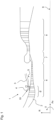
- Fig. 1 shows a schematically illustrated embodiment of an aircraft engine 1 in a meridian section with a main flow channel 2 and a branch channel 3, wherein the branch channel 2 is designed as a secondary flow channel.
- the branch channel 3 branches off from the main flow channel 2 at a connecting area 4, wherein an intermediate housing 5 behind the connecting area 4 separates the two channels 2, 3 from each other in the radial direction.
- the branch channel 3 runs in the present embodiment in Essentially parallel to the main flow channel.
- a compressor 6 with a low-pressure compressor 6 ⁇ , a combustion chamber 7 and a turbine 8 are arranged in the main flow channel 2 in the flow direction, with the connecting region 4 being arranged in the low-pressure compressor 6'.
- the aircraft engine 1 has an engine axis 9, based on which an axial direction Ax running parallel to the engine axis 9, a radial direction R running perpendicular to the engine axis 9 and a circumferential direction U of the engine 1 running around the engine axis are shown.
- An air guide system 10 according to the invention is provided at the connecting region 4, which can separate the main flow channel 2 from the branch flow channel 3.
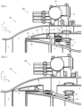
- the air duct system 10 comprises a closure device 20 for separating the branch channel 3 from the main flow channel 2.
- the closure device 20 is shown in an open state
- Fig. 3 the closure device 20 is shown in a closed state.
- the closure device 20 has a closure ring 30 that completely surrounds the main flow channel 2 for closing the connection area 4.
- the closure device 20 also has exactly one actuator 40 for moving the closure ring 30 radially outside the branch channel 3.
- the closure ring 30 can be moved by the actuator 40 in an axial direction Ax and rotated in a circumferential direction U.
- the closure device 20 can thus be adjusted by the actuator 40 to the open state, the closed state or an intermediate position.
- the locking ring 30 is formed from two flat elements 31, 32 connected to one another.
- the two flat elements 31, 32 are formed from sheet metal and are bent in the circumferential direction U.
- the two flat elements each form a surface facing the flow, wherein a first radially inner flat element 31 is flat and slides over a plurality of sliding elements 60, each designed as a sliding block made of polyimide, during an adjustment movement.
- a second, radially outer flat element 32 is in the Fig. 2 shown open state of the closure device 20 faces the flow in the branch channel 3, is curved radially outwards and directs the flow into the downstream branch channel 3.
- the downstream edge of the second flat element 32 is at the same radial height as a housing section of the intermediate housing 5.
- the second flat element 32 rests against this housing section, so that the axial movement of the second flat element 32 is limited by the housing section. This advantageously creates a contact surface in a simple manner.
- the two flat elements 31, 32 are connected to one another at a ring front edge 33, which is a front edge of the closure ring 30 in the axial direction Ax. They form an angle ⁇ of approximately 20°, so that a flow from the main flow channel 2 via the closure ring 30 can flow into the branch channel 3 in a laminar manner and thus with little loss, at least when the closure device 10 is open.
- the locking ring 30 further comprises a stabilizing and strengthening stiffening strut 34 between the two flat elements 31, 32 in an axially rear region, whereby the stiffening strut 34 together with the two flat elements 31, 32 forms a hollow body.
- the locking ring consists of a titanium-based alloy. To produce the locking ring 30, the flat elements 31, 32 of the locking ring 30 are first milled and then welded.
- the actuator 40 of the closure device 20 comprises a hydraulic drive 41, a one-piece drive rod 42 which can be rotated about its longitudinal axis L by the drive 41, and an adjusting lever 50 which is attached to the drive rod 42 and can thus also be pivoted about the longitudinal axis L of the drive rod 42.
- At one end of the adjusting lever 50 remote from the drive rod 42 is this is pivotably connected to the locking ring 30 at a pivot joint 35.
- the pivot joint 35 comprises a pivot axis S which, in the closed state of the locking device, is spaced apart by a distance SL from the longitudinal axis L of the drive rod 42. This advantageously prevents the locking ring 30 from jamming or the drive 41 of the actuator 40 from generating an insufficient torque to close the locking ring 30.
- the locking device 20 comprises an inner housing section 21 of the intermediate housing 5 and an outer housing section 22 of the branch channel 3, wherein the inner and outer housing sections 21, 22 have openings 23 for guiding the rotary cylinder.
- the cross sections of a housing (not shown) of the drive rod 42 are designed at the openings 23 to be complementary to the cross sections of the openings 23 of the housing sections 21, 22, so that as little air as possible can escape from the branch channel.
- the actuator 40 can be actuated.
- the drive 41 of the actuator 40 then rotates the drive rod 42 of the adjustment lever 50.
- the adjustment lever 50 displaces the closure ring 30 in the axial direction Ax and rotates the closure ring 30 in the circumferential direction U.
- a plurality of guide levers 51 are provided, in the present embodiment four, which are evenly spaced apart from one another by the angles ⁇ I-IV .
- Fig. 4 the arrangement of the adjustment lever 50 and the guide lever 51 is shown as an example in a front view of the aircraft engine 1.
- the drive 41 can in particular be arranged in a radially uppermost position.
- the angles ⁇ I-IV can also be designed differently from one another.
Landscapes
- Engineering & Computer Science (AREA)
- Chemical & Material Sciences (AREA)
- Combustion & Propulsion (AREA)
- Mechanical Engineering (AREA)
- General Engineering & Computer Science (AREA)
- Life Sciences & Earth Sciences (AREA)
- Sustainable Development (AREA)
- Structures Of Non-Positive Displacement Pumps (AREA)
Abstract
Die Erfindung betrifft ein Luftführungssystem (10) für ein Flugtriebwerk (1) mit einem Hauptstromkanal (2) und einem Zweigkanal (3), insbesondere kann der Zweigkanal ein Nebenstromkanal und/oder ein Zapfluftkanal sein, wobei der Zweigkanal (3) an einem Verbindungsbereich (4) von dem Hauptstromkanal (2) abzweigt, umfassend eine an oder in dem Verbindungsbereich (4) angeordnete Verschlussvorrichtung (20) zur Trennung des Zweigkanals (3) von dem Hauptstromkanal (2), wobei die Verschlussvorrichtung (20) zumindest einen Verschlussring (30) zum Verschließen des Verbindungsbereichs (4) aufweist.
Description
- Die Erfindung betrifft ein Luftführungssystem für ein Flugtriebwerk mit einem Hauptstromkanal und einem Zweigkanal, insbesondere kann der Zweigkanal ein Nebenstromkanal und/oder ein Zapfluftkanal sein, wobei der Zweigkanal an einem Verbindungsbereich von dem Hauptstromkanal abzweigt.
- In Flugtriebwerken wird die Luft in einem Verdichter, unterteilt in eine Vielzahl von Verdichterstufen, verdichtet, in eine Brennkammer geleitet, mit Kerosin gemischt und gezündet und schließlich in einer Turbine entspannt, um die im Verdichter und der Brennkammer zugeführte Energie zu nutzen. Im Bereich der Verdichter wird eine zumindest teilweise verdichtete Luft in vielen Fällen für andere Zwecke abgeführt. So ist in einigen Flugtriebwerken, insbesondere in für den Überschallbereich konzipierten, sogenannten Low-Bypass-Triebwerken, ein Nebenstromkanal vorgesehen, durch den die nur teilweise verdichtete Luft abgesaugt wird, um einen größeren Vortrieb zu erzeugen. In vielen zivilen Turbofantriebwerken für kommerzielle Einsatzzwecke wird die teilweise verdichtete Luft als Zapfluft für Kabinenapplikationen und zur Kühlung der stromabwärts gelegenen Triebwerkskomponenten wie Brennkammer und Turbine genutzt.
- Dabei kann beispielsweise zur Strömungsführung in einen auch als Bypass-Kanal bezeichneten Nebenstromkanal ein Luftführungssystem erforderlich sein, das den abzuführenden Luftstrom einstellen kann. Bekannt ist beispielsweise ein Triebwerk gemäß
EP2233703A1 , in dem ein Zapfluftsystem mit im Wesentlichen radial verlaufenden Zapfluftkanälen gezeigt ist, dessen Verschlusssystem einen ringförmigen, in Axialrichtung verschiebbaren Verschlussring sowie einen in Axialrichtung neben den Zapfluftkanälen angeordneten Aktuator zur Ansteuerung des Verschlussrings aufweist. Nachteilig ist die Baugröße dieses Luftführungssystems vergleichsweise groß, denn der Aktuator steuert den ringförmigen Verschlussring mittels einer in axialer Richtung verlaufenden Antriebsstange und zwar in einem von einem Verbindungsbereich zwischen Zapfluftkanal und Hauptstromkanal weit beabstandeten Bereich. Dadurch ergibt sich ferner eine verlustbehaftete Lufttasche, wenn der Verschlussring geschlossen ist. Ferner ist der Verschlussring als steifer Vollkörper ausgebildet und somit nachteilig vergleichsweise schwer. - Es ist daher eine Aufgabe der Erfindung ein Luftführungssystem für ein Flugtriebwerk mit einem Hauptstromkanal und einen Zweigkanal anzugeben, das verringerte Verluste erzeugt.
- Zur Lösung dieser Aufgabe wird erfindungsgemäß ein Luftführungssystem nach Anspruch 1 für ein Flugtriebwerk mit einem Hauptstromkanal und einem Zweigkanal vorgeschlagen, insbesondere kann der Zweigkanal ein Nebenstromkanal und/oder ein Zapfluftkanal sein, wobei der Zweigkanal an einem Verbindungsbereich von dem Hauptstromkanal abzweigt. Das Luftführungssystem umfasst eine an oder in dem Verbindungsbereich angeordnete Verschlussvorrichtung zur Trennung des Zweigkanals von dem Hauptstromkanal, wobei die Verschlussvorrichtung zumindest einen Verschlussring zum Verschließen des Verbindungsbereichs aufweist.
- Vorteilhaft wird durch die Anordnung des Verschlussrings in dem Verbindungsbereich zwischen Zweigkanal und Hauptstromkanal in einem geschlossenen Zustand der Verschlussvorrichtung eine bündige Oberfläche in dem Hauptstromkanal geschaffen, so dass ein Luftführungssystem mit sehr geringen Strömungsverlusten geschaffen ist.
- Der Hauptstromkanal kann auch als Kernstromkanal bezeichnet werden. In dem Hauptstromkanal sind in Strömungsrichtung nacheinander zumindest ein Verdichter, eine Brennkammer und zumindest eine Turbine vorgesehen, wobei der Zweigkanal in einem Bereich des Verdichters, insbesondere eines Niederdruckverdichters, abzweigt. Der Hauptstromkanal und der Zweigkanal des Flugtriebwerkes können stromabwärts des Verbindungsbereichs durch ein Zwischengehäuse voneinander in Radialrichtung getrennt angeordnet sein. Der Verschlussring kann vorzugsweise aus einem Metall oder einer Metalllegierung, insbesondere aus Titan oder einer Titanbasislegierung bestehen.
- Weitere Vorteile und Merkmale ergeben sich aus der nachfolgenden Beschreibung einiger bevorzugter Ausführungsbeispiele sowie den abhängigen Ansprüchen.
- In einer ersten Ausführung des Luftführungssystems ist der Verschlussring aus zumindest zwei miteinander verbundenen, zumindest in Umfangsrichtung gebogenen Flachelementen, insbesondere blechartigen ringförmigen Flachelementen, ausgebildet. Die beiden Flachelemente erlauben es vorteilhaft den Verschlussring an die herrschenden Strömungen und das vorhandene Gehäuse des Zweigkanals anzupassen. Gleichzeitig reduziert sich durch die Verwendung zweier Flachelemente vorteilhaft das Gewicht des Verschlussrings. Eine radial innere Oberfläche eines radial unteren ersten Flachelements kann zur Anlage an einem Zwischengehäuseteil dienen. Eine radial äußere Oberfläche des radial oberen zweiten Flachelement kann in einem geschlossenen Zustand der Verschlussvorrichtung auf einer gleichen Höhe in radialer Richtung mit einem nachfolgenden inneren Gehäuseabschnitt des Zweigkanals angeordnet sein und das zweite Flachelement kann insbesondere bündig an dem nachfolgenden inneren Gehäuseabschnitt anliegen. Die Flachelemente können jeweils eine der Strömung zugewandte Oberfläche aufweisen, wobei das erste, radial innere Flachelement in einem geschlossenen Zustand der Verschlussvorrichtung einen radial äußeren Gehäuseabschnitt des Hauptströmungskanals bildet und/oder das zweite, radial äußeres Flachelement, insbesondere in einem geöffneten Zustand der Verschlussvorrichtung, einen radial inneren Gehäuseabschnitt des Zweigkanals bildet. Die Flachelemente des Verschlussrings können zunächst gefräst und dann verschweißt werden.
- In einer bevorzugten Weiterbildung ist ein erstes Flachelement des Verschlussrings in Axialrichtung eben ausgebildet, um ein Gleiten in Axialrichtung zu ermöglichen. Dies verringert den Widerstand und ermöglicht vorteilhaft eine gleichmäßige Bewegung des Verschlussrings.
- In einer besonders bevorzugten Weiterbildung ist ein zweites Flachelement des Verschlussrings in Axialrichtung radial nach außen gekrümmt, insbesondere konvex, ausgebildet, um vorteilhaft ein laminares Überströmen in Axialrichtung der Strömung in dem Zweigkanal zu ermöglichen. Dadurch kann in dem geöffneten Zustand der Verschlussvorrichtung vorteilhaft der Strömungswiderstand verringert werden.
- In einer weiteren Ausbildung des Luftführungssystem sind die beiden Flachelemente an einer Ringvorderkante, die insbesondere eine in Axialrichtung vordere Kante des Verschlussrings ist, miteinander verbunden sind. Dies ermöglicht vorteilhaft eine steifen und gleichzeitig leichte Ausführungsform des Verschlussrings. Bevorzugt bilden die Flachelemente einen Winkel, so dass vorteilhaft eine Strömung aus dem Hauptstromkanal über der Verschlussring zumindest in einem geöffneten Zustand des Verschlussvorrichtung verlustarm in den Zweigkanal strömen kann. Der Winkel kann zumindest 10° und höchstens 45° betragen, insbesondere wenn es sich bei dem Zweigkanal um einen Nebenstromkanal handelt. Der Winkel kann bevorzugt mehr als 30° und höchstens 90° betragen, insbesondere wenn es sich bei dem Zweigkanal um einen Zapfluftkanal handelt.
- In einer weiteren Ausbildung des Luftführungssystems sind die beiden Flachelemente durch eine Versteifungsstrebe, insbesondere zu einem Hohlkörper, verbunden. Es können auch mehrere Versteifungsstreben in Umfangsrichtung verteilt vorgesehen sein. Durch Versteifungsstreben kann vorteilhaft die Steifigkeit des Verschlussrings weiter erhöht werden, ohne dass das Gewicht stark zunimmt. Die Versteifungsstrebe kann in einem in Axialrichtung hinteren Bereich des Verschlussrings angeordnet sein. Ihre größte Ausdehnung in einem Querschnitt in einem Meridianschnitt kann sich in Radialrichtung erstrecken oder zu der Radialrichtung angewinkelt verlaufen.
- Ferner kann in einer Ausbildung des Luftführungssystems der Verschlussring, insbesondere mit dem eben ausgebildeten ersten Flachelement, über zumindest ein radial innen in dem Zweigkanal befestigtes Gleitelement gleiten, insbesondere wobei das Gleitelement als ein Gleitstein aus einem Kunststoff, besonders bevorzugt aus einem Polyimid, ausgebildet ist. Dies ermöglicht eine besonders reibungsarme Bewegung des Verschlussrings. Es kann vorgesehen sein, dass eine Mehrzahl von Gleitelementen in Umfangsrichtung an dem Zwischengehäuse verteilt befestigt ist und in Radialrichtung innerhalb des ersten Flachelements angeordnet ist.
- Darüber hinaus kann in dem Luftführungssystem vorgesehen sein, dass die Verschlussvorrichtung einen, insbesondere genau einen, Aktuator zum Verschieben des Verschlussrings aufweist. Insbesondere durch die hohe Steifigkeit des Verschlussrings und das geringe Gewicht des Verschlussrings aufgrund der Flachelemente kann ein Aktuator vorteilhaft vergleichsweise klein ausgebildet sein, denn der Aktuator muss geringere Kräfte aufbringen, um den Verschlussring zu bewegen. Die Verschlussvorrichtung kann durch den Aktuator in einen geöffneten Zustand, in einen geschlossenen Zustand oder eine Zwischenstellung verstellt werden. In einigen Ausführungsformen des Luftführungssystems kann vorgesehen sein, dass mehrere Aktuatoren in Umfangsrichtung verteilt vorgesehen sind.
- In einer bevorzugten Ausführung des Luftführungssystems ist ferner vorgesehen, dass der Verschlussring von dem Aktuator in eine Axialrichtung und Umfangsrichtung verschiebbar ist. Dies kann insbesondere durch eine Drehbewegung mit gleichzeitiger axialer Verschiebung erzielt werden. Eine solche Kinematik erlaubt es einen besonders einen Aktuator mit Drehantrieb vorzusehen, der in der regelmäßig vorteilhaft einen geringeren Bauraum einnimmt als beispielsweise ein Linearaktuator.
- In einer besonders bevorzugten Weiterbildung des Luftführungssystem ist ein Antrieb des Aktuators radial außerhalb des Zweigkanals angeordnet. Dies erlaubt es vorteilhaft auf einfache Weise den inneren Bauraum des Zwischengehäuses zwischen Zweigkanal und Hauptstromkanal klein zu halten. Der Antrieb kann in einem Querschnitt normal zur Axialrichtung insbesondere in einer radial obersten Position angeordnet sein. Dies erlaubt es dem Antrieb beim Verschieben des Verschlussrings vorteilhaft kaum gegen die Gewichtskraft des Verschlussrings arbeiten zu müssen. Der Antrieb kann ein elektrischer Motor oder ein hydraulischer Antrieb, insbesondere hydraulischer Zylinder sein.
- Darüber hinaus kann der Aktuator des Luftführungssystem derart weitergebildet sein, dass eine Antriebsstange, des Aktuators von radial außerhalb des Zweigkanals durch den Zweigkanal und in ein den Hauptstromkanal und den Zweigkanal radial voneinander trennendes Zwischengehäuse geführt und durch einen Verstellhebel des Aktuators mit dem Verschlussring schwenkbar verbunden ist, um den Verschlussring in Axialrichtung und Umfangsrichtung zu verschieben. Die Führung des Antriebsstange durch den Zweigkanal erlaubt vorteilhaft den Bauraum im Triebwerk selbst zu verringern und insbesondere im Fall des Nebenstromkanals diesen nahe des Hauptstromkanals anzuordnen, um den Nebenstrom mit dem Hauptstrom auf einfache Weise wieder zusammenführen zu können und/oder die weiter stromabwärts angeordneten Komponenten des Flugtriebwerks effizient kühlen zu können. Das Flugtriebwerk muss entsprechend angepasst sein. Die Antriebsstange kann einstückig ausgebildet sein und/oder ein Gehäuse aufweisen. Die Verschlussvorrichtung kann einen inneren Gehäuseabschnitt und einen äußeren Gehäuseabschnitt des Zweigkanals umfassen, wobei die inneren und äußeren Gehäuseabschnitte Öffnungen zur Führung des Drehzylinders aufweisen. Die Querschnitte der Antriebsstange und/oder ihres Gehäuses kann an den Öffnungen komplementär zu den Querschnitten der Öffnungen der Gehäuseabschnitte ausgebildet sein. Eine Schwenkachse des Verstellhebels an dem Verschlussring kann einer vorteilhaften Weiterbildung in Axialrichtung vor einer Längsachse der Antriebsstange angeordnet sein, so dass die Drehmomentaufbringung durch den Aktuator stets ausreichend ist und so vorteilhaft eine Schließbewegung stabil ausgeführt werden kann.
- In einer weiteren bevorzugten Weiterbildung des Luftführungssystems ist zumindest ein Führungshebel der Verschlussvorrichtung mit dem Zwischengehäuse schwenkbar verbunden, um eine Gleitbewegung des Verschlussrings zu stabilisieren. Es können auch mehrere Führungshebel in Umfangsrichtung verteilt in dem Zwischengehäuse angeordnet sein.
- Schließlich wird in einem weiteren erfindungsgemäßen Aspekt ein Flugtriebwerk mit einem Hauptstromkanal und einem Zweigkanal vorgeschlagen, wobei der Zweigkanal an einem Verbindungsbereich von dem Hauptstromkanal abzweigt, umfassend eines der oben beschriebenen Luftführungssysteme. Das Flugtriebwerk kann insbesondere ein Low-Bypass-Flugtriebwerk sein.
- Die Erfindung wird bezüglich der nachfolgenden Zeichnungen anhand eines bevorzugten Ausführungsbeispiels der Erfindung näher erläutert.
- Fig. 1
- zeigt ein Ausführungsbeispiel eines erfindungsgemäßen Flugtriebwerks mit einem ersten Ausführungsbeispiel eines erfindungsgemäßen Luftführungssystems
- Fig. 2
- zeigt das erste Ausführungsbeispiel eines erfindungsgemäßen Luftführungssystems in einem geöffneten Zustand
- Fig. 3
- zeigt das erste Ausführungsbeispiel des erfindungsgemäßen Luftführungssystems in einem geschlossenen Zustand
- Fig. 4
- zeigt das erste Ausführungsbeispiel eines erfindungsgemäßen Luftführungssystem in einer Frontansicht
-
Fig. 1 zeigt ein schematisch dargestelltes Ausführungsbeispiel eines Flugtriebwerks 1 in einem Meridianschnitt mit einem Hauptstromkanal 2 und einem Zweigkanal 3, wobei der Zweigkanal 2 als ein Nebenstromkanal ausgebildet ist. Der Zweigkanal 3 zweigt an einem Verbindungsbereich 4 von dem Hauptstromkanal 2 ab, wobei ein Zwischengehäuse 5 hinter dem Verbindungsbereich 4 die beiden Kanäle 2, 3 in radialer Richtung voneinander trennt. Der Zweigkanal 3 verläuft in dem vorliegenden Ausführungsbeispiel im Wesentlichen parallel zu dem Hauptstromkanal. In dem Hauptstromkanal 2 sind in Strömungsrichtung ein Verdichter 6 mit einem Niederdruckverdichter 6`, eine Brennkammer 7 und eine Turbine 8 angeordnet, wobei der Verbindungsbereich 4 in dem Niederdruckverdichter 6' angeordnet ist. Das Flugtriebwerk 1 weist eine Triebwerksachse 9 auf, anhand derer eine parallel zu der Triebwerksachse 9 verlaufende Axialrichtung Ax, eine senkrecht zu der Triebwerksachse 9 verlaufende Radialrichtung R und eine um die Triebwerksachse verlaufende Umfangsrichtung U des Triebwerks 1 dargestellt sind. - An dem Verbindungsbereich 4 ist ein erfindungsgemäßes Luftführungssystem 10 vorgesehen, das den Hauptstromkanal 2 von dem Zweigstromkanal 3 trennen kann.
- In den
Fig. 2 und 3 ist das erste Ausführungsbeispiel des erfindungsgemäßen Luftführungssystems 10 näher beschrieben. Das Luftführungssystem 10 umfasst eine Verschlussvorrichtung 20 zur Trennung des Zweigkanals 3 von dem Hauptstromkanal 2. InFig. 2 ist die Verschlussvorrichtung 20 in einem geöffneten Zustand gezeigt, inFig. 3 ist die Verschlussvorrichtung 20 in einem geschlossenen Zustand gezeigt. - Dabei weist die Verschlussvorrichtung 20 einen den Hauptstromkanal 2 vollständig umlaufenden Verschlussring 30 zum Verschließen des Verbindungsbereichs 4 auf. Ferner weist die Verschlussvorrichtung 20 genau einen Aktuator 40 zum Verschieben des Verschlussrings 30 radial außerhalb des Zweigkanals 3 auf. Der Verschlussring 30 kann von dem Aktuator 40 in eine Axialrichtung Ax verschoben und Umfangsrichtung U gedreht werden. Die Verschlussvorrichtung 20 kann dadurch durch den Aktuator 40 in den geöffneten Zustand, in den geschlossenen Zustand oder in eine Zwischenstellung verstellt werden.
- Der Verschlussring 30 ist aus zwei miteinander verbundenen Flachelementen 31, 32 ausgebildet. Die beiden Flachelemente 31, 32 sind blechförmig ausgebildet und in Umfangsrichtung U gebogenen. Die beiden Flachelemente bilden jeweils eine der Strömung zugewandte Oberfläche, wobei ein erstes radial inneres Flachelement 31 eben ausgebildet ist und bei einer Verstellbewegung über eine Vielzahl von als jeweils ein Gleitstein aus Polyimid ausgebildete Gleitelemente 60 gleitet. Ein zweites, radial äußeres Flachelement 32 ist in dem in
Fig. 2 gezeigten geöffneten Zustand der Verschlussvorrichtung 20 der Strömung in dem Zweigkanal 3 zugewandt, radial nach außen gekrümmt ausgebildet und leitet die Strömung in den stromabwärtigen Zweigkanal 3. Die stromabwärtige Kante des zweiten Flachelements 32 ist dabei auf gleicher radialer Höhe wie ein Gehäuseabschnitt des Zwischengehäuses 5. Das zweite Flachelement 32 liegt an diesem Gehäuseabschnitt an, so dass die axiale Bewegung des zweiten Flachelements 32 durch den Gehäuseabschnitt begrenzt wird. Somit ist vorteilhaft auf einfache Weise eine Anlagefläche geschaffen. Die beiden Flachelemente 31, 32 sind an einer Ringvorderkante 33, die eine in Axialrichtung Ax vordere Kante des Verschlussrings 30 ist, miteinander verbunden. Sie bilden einen Winkel α von etwa 20°, so dass eine Strömung aus dem Hauptstromkanal 2 über den Verschlussring 30 zumindest in einem geöffneten Zustand des Verschlussvorrichtung 10 laminar und damit verlustarm in den Zweigkanal 3 strömen kann. - Der Verschlussring 30 umfasst in einem axial hinteren Bereich ferner eine stabilisierende und festigende Versteifungsstrebe 34 zwischen den beiden Flachelementen 31, 32, wobei die Versteifungsstrebe 34 zusammen mit den beiden Flachelementen 31, 32 einen Hohlkörper ausgebildet. Der Verschlussring besteht aus einer Titanbasislegierung. Zur Herstellung des Verschlussrings 30 werden die Flachelemente 31, 32 des Verschlussrings 30 zunächst gefräst und dann verschweißt.
- Der Aktuator 40 der Verschlussvorrichtung 20 umfasst einen hydraulischen Antrieb 41, eine einstückig ausgebildete Antriebsstange 42, die um ihre Längsachse L von dem Antrieb 41 rotiert werden kann, sowie einen Verstellhebel 50, der an der Antriebsstange 42 befestigt ist und somit ebenfalls um die Längsachse L der Antriebsstange 42 verschwenkt werden kann. An einem der Antriebsstange 42 abgelegenen Ende des Verstellhebels 50 ist dieser an dem Verschlussring 30 schwenkbar an einem Schwenkgelenk 35 angelenkt. Das Schwenkgelenk 35 umfasst eine Schwenkachse S, die in dem geschlossenen Zustand der Verschlussvorrichtung um einen Abstand SL von der Längsachse L der Antriebsstange 42 beabstandet ist. Dadurch wird vorteilhaft verhindert, dass sich der Verschlussrings 30 verklemmt oder von dem Antrieb 41 des Aktuator 40 ein nicht ausreichend großes Drehmoment erzeugt werden kann, um den Verschlussring 30 zu schließen. Die Verschlussvorrichtung 20 umfasst einen inneren Gehäuseabschnitt 21 des Zwischengehäuses 5 und einen äußeren Gehäuseabschnitt 22 des Zweigkanals 3, wobei die inneren und äußeren Gehäuseabschnitte 21, 22 Öffnungen 23 zur Führung des Drehzylinders aufweisen. Die Querschnitte eines nicht dargestellten Gehäuses der Antriebsstange 42 sind an den Öffnungen 23 komplementär zu den Querschnitten der Öffnungen 23 der Gehäuseabschnitte 21, 22 ausgebildet, so dass möglichst wenig Luft aus dem Zweigkanal entweichen kann.
- Um die Verschlussvorrichtung 20 zu schließen und den Verschlussring 30 in dem Verbindungsbereich 4 zwischen dem Hauptstromkanal 2 und dem Zweigkanal 3 anzuordnen, kann der Aktuator 40 betätigt werden. Der Antrieb 41 des Aktuators 40 dreht dann die Antriebsstange 42 den Verstellhebel 50. Der Verstellhebel 50 verschiebt den Verschlussring 30 in Axialrichtung Ax und dreht den Verschlussring 30 in Umfangsrichtung U.
- Um die Führung des Verschlussrings 30 gleichmäßig in Umfangsrichtung U zu gewährleisten sind eine Vielzahl, in dem vorliegenden Ausführungsbeispiel vier gleichmäßig um die Winkel βI-IV von einander beabstandete Führungshebel 51 vorgesehen. In
Fig. 4 ist die Anordnung des Verstellhebels 50 und der Führungshebel 51 beispielhaft in einer Frontansicht des Flugtriebwerks 1 dargestellt. Der Antrieb 41 kann dabei insbesondere in einer radial obersten Position angeordnet sein. Die Winkel βI-IV können auch voneinander verschieden ausgebildet sein. -
- 1
- Flugtriebwerk
- 2
- Hauptstromkanal
- 3
- Zweigkanal
- 4
- Verbindungsbereich
- 5
- Zwischengehäuse
- 6
- Verdichter
- 6`
- Niederdruckverdichter
- 7
- Brennkammer
- 8
- Turbine
- 9
- Triebwerksachse
- 10
- Luftführungssystem
- 20
- Verschlussvorrichtung
- 21
- Innerer Gehäuseabschnitt
- 22
- Äußerer Gehäuseabschnitt
- 30
- Verschlussring
- 31
- Erstes, radial inneres Flachelement
- 32
- Zweites, radial äußeres Flachelement
- 33
- Ringkante, Ringvorderkante
- 34
- Versteifungsstrebe
- 35
- Schwenkgelenk
- 40
- Aktuator
- 41
- Antrieb
- 42
- Antriebsstange
- 50
- Schwenkhebel
- 51
- Führungshebel
- 60
- Gleitelement
- Ax
- Axialrichtung
- R
- Radialrichtung
- U
- Umfangsrichtung
- L
- Längsachse der Antriebsstange
- S
- Schwenkachse des Schwenkhebels an dem Verschlussring
- SL
- Abstand zwischen Schwenk- und Längsachse
- α
- Winkel zwischen den Flachelementen
- β-βiv
- Winkel zwischen den Schwenkhebeln und/oder den Führungshebeln
Claims (13)
- Luftführungssystem (10) für ein Flugtriebwerk (1) mit einem Hauptstromkanal (2) und einem Zweigkanal (3), insbesondere kann der Zweigkanal ein Nebenstromkanal und/oder ein Zapfluftkanal sein, wobei der Zweigkanal (3) an einem Verbindungsbereich (4) von dem Hauptstromkanal (2) abzweigt, umfassendeine an oder in dem Verbindungsbereich (4) angeordnete Verschlussvorrichtung (20) zur Trennung des Zweigkanals (3) von dem Hauptstromkanal (2),wobei die Verschlussvorrichtung (20) zumindest einen Verschlussring (30) zum Verschließen des Verbindungsbereichs (4) aufweist.
- Luftführungssystem gemäß Anspruch 1, wobei der Verschlussring (30) aus zumindest zwei miteinander verbundenen zumindest in Umfangsrichtung (U) gebogenen Flachelementen (31, 32), insbesondere blechartigen ringförmigen Flachelementen (31, 32), ausgebildet ist.
- Luftführungssystem gemäß Anspruch 2, wobei ein erstes Flachelement (31) des Verschlussrings (30) in Axialrichtung eben ausgebildet ist, um ein Gleiten in Axialrichtung zu ermöglichen.
- Luftführungssystem nach Anspruch 2 oder 3, wobei ein zweites Flachelement (32) des Verschlussrings (30) in Axialrichtung (Ax) radial nach außen gekrümmt ausgebildet ist.
- Luftführungssystem nach einem der vorangehenden 2 bis 4, wobei die beiden Flachelemente (31, 32) an einer Ringvorderkante (33), die insbesondere eine in Axialrichtung (Ax) vordere Kante des Verschlussrings (30) ist, miteinander verbunden sind, und bevorzugt einen Winkel (α) bilden.
- Luftführungssystem nach einem der Ansprüche 2 bis 5, wobei die beiden Flachelemente (31, 32) durch eine Versteifungsstrebe (34), insbesondere zu einem Hohlkörper, verbunden sind.
- Luftführungssystem nach einem der vorangehenden Ansprüche, wobei der Verschlussring (30), insbesondere mit dem eben ausgebildeten ersten Flachelement (31), über zumindest ein radial innen in dem Zweigkanal (3) befestigtes Gleitelement (60) gleitet, insbesondere wobei das Gleitelement (60) als ein Gleitstein aus einem Kunststoff, besonders bevorzugt aus einem Polyimid, ausgebildet ist.
- Luftführungssystem nach einem der vorangehenden Ansprüche, wobei die Verschlussvorrichtung (20) einen, insbesondere genau einen, Aktuator (40) zum Verschieben des Verschlussrings (30) aufweist.
- Luftführungssystem gemäß Anspruch 8, wobei der Verschlussring (30) von dem Aktuator (40) in eine Axialrichtung (Ax) und Umfangsrichtung (U) verschiebbar ist.
- Luftführungssystem nach einem der Ansprüche 8 oder 9, wobei ein Antrieb (41) des Aktuators (40) radial außerhalb des Zweigkanals (3) angeordnet ist.
- Luftführungssystem nach einem der Ansprüche 8 bis 10, wobei eine Antriebsstange (42), des Aktuators (40) von radial außerhalb des Zweigkanals (3) durch den Zweigkanal (3) und in ein den Hauptstromkanal (2) und den Zweigkanal (3) radial voneinander trennendes Zwischengehäuse (5) geführt und durch einen Verstellhebel (43) des Aktuators (40) mit dem Verschlussring (20) schwenkbar verbunden ist, um den Verschlussring (20) in Axialrichtung (Ax) und Umfangsrichtung (U) zu verschieben.
- Luftführungssystem nach Anspruch 11, wobei zumindest ein Führungshebel (51) der Verschlussvorrichtung (10) mit dem Zwischengehäuse (5) schwenkbar verbunden ist, um eine Gleitbewegung des Verschlussrings (20) zu stabilisieren.
- Flugtriebwerk (1) mit einem Hauptstromkanal (2) und einem Zweigkanal (3), wobei der Zweigkanal (3) an einem Verbindungsbereich (4) von dem Hauptstromkanal (2) abzweigt, umfassend ein Luftführungssystem (10) nach einem der vorangehenden Ansprüche.
Applications Claiming Priority (1)
| Application Number | Priority Date | Filing Date | Title |
|---|---|---|---|
| DE102023121050.5A DE102023121050A1 (de) | 2023-08-08 | 2023-08-08 | Luftführungssystem |
Publications (1)
| Publication Number | Publication Date |
|---|---|
| EP4506548A1 true EP4506548A1 (de) | 2025-02-12 |
Family
ID=92108398
Family Applications (1)
| Application Number | Title | Priority Date | Filing Date |
|---|---|---|---|
| EP24190980.3A Pending EP4506548A1 (de) | 2023-08-08 | 2024-07-25 | Luftführungssystem |
Country Status (3)
| Country | Link |
|---|---|
| US (1) | US12435670B2 (de) |
| EP (1) | EP4506548A1 (de) |
| DE (1) | DE102023121050A1 (de) |
Citations (4)
| Publication number | Priority date | Publication date | Assignee | Title |
|---|---|---|---|---|
| US4679982A (en) * | 1984-09-06 | 1987-07-14 | Societe Nationale D'etude Et De Construction De Moteur D'aviation "S. N. E. C. M. A." | Compressor blow-off arrangement |
| US20050072158A1 (en) * | 2003-10-07 | 2005-04-07 | Christopherson Charles Kammer | Gas turbine engine with variable pressure ratio fan system |
| EP2233703A2 (de) | 2009-03-26 | 2010-09-29 | United Technologies Corporation | Gasturbinen-Triebwerk mit Zapfleitung im Kerngehäuse |
| DE102013215371A1 (de) * | 2013-08-05 | 2015-02-05 | Rolls-Royce Deutschland Ltd & Co Kg | Vorrichtung und Verfahren zum Abblasen von Verdichterluft in einem Triebwerk |
Family Cites Families (3)
| Publication number | Priority date | Publication date | Assignee | Title |
|---|---|---|---|---|
| FR2569783B1 (fr) * | 1984-09-06 | 1986-09-12 | Snecma | Structure d'anneau et dispositif de decharge de compresseur comportant cet anneau |
| DE102014217830A1 (de) * | 2014-09-05 | 2016-03-10 | Rolls-Royce Deutschland Ltd & Co Kg | Luftleitvorrichtung und Turbomaschine mit Luftleitvorrichtung |
| US12366202B2 (en) * | 2022-01-18 | 2025-07-22 | General Electric Company | Bleed valve assemblies |
-
2023
- 2023-08-08 DE DE102023121050.5A patent/DE102023121050A1/de active Pending
-
2024
- 2024-07-25 EP EP24190980.3A patent/EP4506548A1/de active Pending
- 2024-08-01 US US18/792,356 patent/US12435670B2/en active Active
Patent Citations (4)
| Publication number | Priority date | Publication date | Assignee | Title |
|---|---|---|---|---|
| US4679982A (en) * | 1984-09-06 | 1987-07-14 | Societe Nationale D'etude Et De Construction De Moteur D'aviation "S. N. E. C. M. A." | Compressor blow-off arrangement |
| US20050072158A1 (en) * | 2003-10-07 | 2005-04-07 | Christopherson Charles Kammer | Gas turbine engine with variable pressure ratio fan system |
| EP2233703A2 (de) | 2009-03-26 | 2010-09-29 | United Technologies Corporation | Gasturbinen-Triebwerk mit Zapfleitung im Kerngehäuse |
| DE102013215371A1 (de) * | 2013-08-05 | 2015-02-05 | Rolls-Royce Deutschland Ltd & Co Kg | Vorrichtung und Verfahren zum Abblasen von Verdichterluft in einem Triebwerk |
Also Published As
| Publication number | Publication date |
|---|---|
| DE102023121050A1 (de) | 2025-02-13 |
| US20250052197A1 (en) | 2025-02-13 |
| US12435670B2 (en) | 2025-10-07 |
Similar Documents
| Publication | Publication Date | Title |
|---|---|---|
| DE3851420T2 (de) | Strahlumkehrvorrichtung für ein Bläsertriebwerk. | |
| DE3844188C1 (de) | ||
| EP3306066B1 (de) | Turbofan-triebwerk für ein ziviles überschallflugzeug | |
| DE60226288T2 (de) | Kaskadenförmige Schubumkehrvorrichtung | |
| DE3121653C2 (de) | ||
| DE2644092C2 (de) | Verstellbare konvergent-divergente Schubdüse für ein Gasturbinentriebwerk | |
| DE69902618T2 (de) | Schubumkehrvorrichtung mit teleskopischen Gittern | |
| DE69704798T2 (de) | Schubumkehrvorrichtung für ein Strahltriebwerk mit an der Vorseite der Hauptklappen verbundenen Hilfsklappen | |
| DE2815573A1 (de) | Abgasduese mit veraenderlichem durchtrittsquerschnitt fuer gasturbinen und hebelgetriebeanordnung fuer eine solche abgasduese | |
| EP2835522B1 (de) | Vorrichtung und Verfahren zum Abblasen von Verdichterluft in einem Triebwerk | |
| DE1456037B1 (de) | Schubumkehreinrichtung für ein Strahltriebwerk | |
| DE1228107B (de) | Strahltriebwerk-Schubduese | |
| DE1285328B (de) | Strahltriebwerk mit Strahlumlenkung | |
| EP3388649A1 (de) | Triebwerksgondel für ein turbofan-triebwerk | |
| DE3242822C2 (de) | ||
| DE1279478B (de) | Strahltriebwerk, insbesondere Mantelstromtriebwerk, mit Strahlumlenkklappen | |
| WO2019121022A1 (de) | Schubdüse für ein turbofan-triebwerk eines überschallflugzeugs | |
| DE3242824A1 (de) | Schubduesenanordnung mit veraenderbarer querschnittsflaeche fuer ein gasturbinentriebwerk | |
| EP3366907B1 (de) | Konvergent-divergente schubdüse für ein turbofan-triebwerk eines überschallflugzeugs und verfahren zur einstellung der düsenhalsfläche in einer schubdüse eines turbofan-triebwerks | |
| DE1287444B (de) | Schubumkehrvorrichtung fuer ein Mantelstromstrahltriebwerk | |
| DE2638882A1 (de) | Ausstroemduese mit austrittskonus und klappe fuer variablen betriebszyklus und verfahren zum betrieb derselben | |
| DE60017491T2 (de) | Allseitig schwenkbare konvergente - divergente Schubdüse mit einem kardanischen Bedienungsring | |
| DE3242823C2 (de) | ||
| DE1481553A1 (de) | Einrichtung zur Betaetigung der Austrittsleitklappen an Auftriebsgeblaesen | |
| DE2834860A1 (de) | Verstellbarer stroemungsteiler fuer stroemungsmaschinen, insbesondere gasturbinenstrahltriebwerke |
Legal Events
| Date | Code | Title | Description |
|---|---|---|---|
| PUAI | Public reference made under article 153(3) epc to a published international application that has entered the european phase |
Free format text: ORIGINAL CODE: 0009012 |
|
| STAA | Information on the status of an ep patent application or granted ep patent |
Free format text: STATUS: THE APPLICATION HAS BEEN PUBLISHED |
|
| AK | Designated contracting states |
Kind code of ref document: A1 Designated state(s): AL AT BE BG CH CY CZ DE DK EE ES FI FR GB GR HR HU IE IS IT LI LT LU LV MC ME MK MT NL NO PL PT RO RS SE SI SK SM TR |
|
| STAA | Information on the status of an ep patent application or granted ep patent |
Free format text: STATUS: REQUEST FOR EXAMINATION WAS MADE |
|
| 17P | Request for examination filed |
Effective date: 20250811 |