EP3366907B1 - Konvergent-divergente schubdüse für ein turbofan-triebwerk eines überschallflugzeugs und verfahren zur einstellung der düsenhalsfläche in einer schubdüse eines turbofan-triebwerks - Google Patents
Konvergent-divergente schubdüse für ein turbofan-triebwerk eines überschallflugzeugs und verfahren zur einstellung der düsenhalsfläche in einer schubdüse eines turbofan-triebwerks Download PDFInfo
- Publication number
- EP3366907B1 EP3366907B1 EP18158530.8A EP18158530A EP3366907B1 EP 3366907 B1 EP3366907 B1 EP 3366907B1 EP 18158530 A EP18158530 A EP 18158530A EP 3366907 B1 EP3366907 B1 EP 3366907B1
- Authority
- EP
- European Patent Office
- Prior art keywords
- nozzle
- wall
- thrust nozzle
- ring
- region
- Prior art date
- Legal status (The legal status is an assumption and is not a legal conclusion. Google has not performed a legal analysis and makes no representation as to the accuracy of the status listed.)
- Active
Links
Images


Classifications
-
- F—MECHANICAL ENGINEERING; LIGHTING; HEATING; WEAPONS; BLASTING
- F02—COMBUSTION ENGINES; HOT-GAS OR COMBUSTION-PRODUCT ENGINE PLANTS
- F02K—JET-PROPULSION PLANTS
- F02K1/00—Plants characterised by the form or arrangement of the jet pipe or nozzle; Jet pipes or nozzles peculiar thereto
- F02K1/06—Varying effective area of jet pipe or nozzle
- F02K1/08—Varying effective area of jet pipe or nozzle by axially moving or transversely deforming an internal member, e.g. the exhaust cone
-
- B—PERFORMING OPERATIONS; TRANSPORTING
- B64—AIRCRAFT; AVIATION; COSMONAUTICS
- B64C—AEROPLANES; HELICOPTERS
- B64C30/00—Supersonic type aircraft
-
- B—PERFORMING OPERATIONS; TRANSPORTING
- B64—AIRCRAFT; AVIATION; COSMONAUTICS
- B64D—EQUIPMENT FOR FITTING IN OR TO AIRCRAFT; FLIGHT SUITS; PARACHUTES; ARRANGEMENT OR MOUNTING OF POWER PLANTS OR PROPULSION TRANSMISSIONS IN AIRCRAFT
- B64D27/00—Arrangement or mounting of power plants in aircraft; Aircraft characterised by the type or position of power plants
- B64D27/02—Aircraft characterised by the type or position of power plants
- B64D27/16—Aircraft characterised by the type or position of power plants of jet type
- B64D27/20—Aircraft characterised by the type or position of power plants of jet type within, or attached to, fuselages
-
- B—PERFORMING OPERATIONS; TRANSPORTING
- B64—AIRCRAFT; AVIATION; COSMONAUTICS
- B64D—EQUIPMENT FOR FITTING IN OR TO AIRCRAFT; FLIGHT SUITS; PARACHUTES; ARRANGEMENT OR MOUNTING OF POWER PLANTS OR PROPULSION TRANSMISSIONS IN AIRCRAFT
- B64D33/00—Arrangement in aircraft of power plant parts or auxiliaries not otherwise provided for
- B64D33/04—Arrangement in aircraft of power plant parts or auxiliaries not otherwise provided for of exhaust outlets or jet pipes
-
- F—MECHANICAL ENGINEERING; LIGHTING; HEATING; WEAPONS; BLASTING
- F02—COMBUSTION ENGINES; HOT-GAS OR COMBUSTION-PRODUCT ENGINE PLANTS
- F02K—JET-PROPULSION PLANTS
- F02K1/00—Plants characterised by the form or arrangement of the jet pipe or nozzle; Jet pipes or nozzles peculiar thereto
- F02K1/06—Varying effective area of jet pipe or nozzle
- F02K1/15—Control or regulation
-
- F—MECHANICAL ENGINEERING; LIGHTING; HEATING; WEAPONS; BLASTING
- F02—COMBUSTION ENGINES; HOT-GAS OR COMBUSTION-PRODUCT ENGINE PLANTS
- F02K—JET-PROPULSION PLANTS
- F02K1/00—Plants characterised by the form or arrangement of the jet pipe or nozzle; Jet pipes or nozzles peculiar thereto
- F02K1/46—Nozzles having means for adding air to the jet or for augmenting the mixing region between the jet and the ambient air, e.g. for silencing
-
- F—MECHANICAL ENGINEERING; LIGHTING; HEATING; WEAPONS; BLASTING
- F02—COMBUSTION ENGINES; HOT-GAS OR COMBUSTION-PRODUCT ENGINE PLANTS
- F02K—JET-PROPULSION PLANTS
- F02K3/00—Plants including a gas turbine driving a compressor or a ducted fan
- F02K3/02—Plants including a gas turbine driving a compressor or a ducted fan in which part of the working fluid by-passes the turbine and combustion chamber
- F02K3/04—Plants including a gas turbine driving a compressor or a ducted fan in which part of the working fluid by-passes the turbine and combustion chamber the plant including ducted fans, i.e. fans with high volume, low pressure outputs, for augmenting the jet thrust, e.g. of double-flow type
- F02K3/06—Plants including a gas turbine driving a compressor or a ducted fan in which part of the working fluid by-passes the turbine and combustion chamber the plant including ducted fans, i.e. fans with high volume, low pressure outputs, for augmenting the jet thrust, e.g. of double-flow type with front fan
-
- F—MECHANICAL ENGINEERING; LIGHTING; HEATING; WEAPONS; BLASTING
- F05—INDEXING SCHEMES RELATING TO ENGINES OR PUMPS IN VARIOUS SUBCLASSES OF CLASSES F01-F04
- F05D—INDEXING SCHEME FOR ASPECTS RELATING TO NON-POSITIVE-DISPLACEMENT MACHINES OR ENGINES, GAS-TURBINES OR JET-PROPULSION PLANTS
- F05D2220/00—Application
- F05D2220/80—Application in supersonic vehicles excluding hypersonic vehicles or ram, scram or rocket propulsion
Definitions
- the invention relates to a convergent-divergent thruster for a turbofan engine of a supersonic aircraft according to the preamble of claim 1 and a method for adjusting the nozzle neck area in a thruster of a turbofan engine.
- a convergent-divergent thrust nozzle that has a nozzle neck surface (usually referred to as A8) and a nozzle exit surface (usually referred to as A9)
- A8 nozzle neck surface
- A9 nozzle exit surface
- a thrust nozzle with a variable contour for example as an iris / petal nozzle with a large number of individually adjustable slats. It is known to provide a group of convergent lamellae and a group of divergent lamellae in a thrust nozzle, each of which is arranged in a circle. The individual slats are provided with actuators for their adjustability.
- a thruster is for example from the US 9,464,594 B2 as well as from the engines of the McDonnell Douglas F-15, Suchoi Su-27 and Suchoi Su-34 fighter jets.
- Disadvantages of thrusters in Iris / Petal construction are a complex structure, high maintenance intensity, complex control and a relatively high weight due to the need for a large number of actuators. There are also high flow losses at the individual fins.
- a thrust nozzle arrangement is known in which a gas turbine has separate thrusters for the bypass duct, the primary flow duct and for a mixer.
- the mixer is assigned an axially displaceable cladding ring, the axial position of which changes the outlet cross section of the thrust nozzle assigned to the mixer.
- the US 3,598,318 A describes a turbofan engine with a generic convergent-divergent thrust nozzle which is formed between a central body and a housing wall. Swiveling flaps are arranged on the central body. In a first position, these extend inside the thrust nozzle and thereby form an annular structure. In the first position, they serve to divide the gas flow in the thrust nozzle into an inner and an outer area. In a second position, the flaps rest on the central body. In a third position, the flaps are set up in such a way that they block the gas flow in the thrust nozzle.
- a turbofan engine in which the air flow in a bypass duct is divided into two partial flows upstream of a thrust nozzle via a flap arrangement.
- Inner cladding elements and outer cladding elements as well as a sliding flap are provided in the bypass channel. By moving all of these elements, the cross-sectional areas over which the air flow in the bypass duct is divided into two partial flows can be varied.
- the valve arrangement serves as a flow limiter.
- the present invention is based on the object of providing a thrust nozzle of a turbofan engine which is suitable for supersonic operation, and a method which make it possible to set the nozzle neck surface in an efficient manner.
- the present invention provides for a cladding ring which can be displaced between a first position and a second position in the axial direction to be provided in a convergent-divergent thrust nozzle.
- the inner wall of the thrust nozzle and the cladding ring are designed and positioned relative to one another in such a way that the cladding ring in the first position protrudes radially and runs radially inward to the inner wall, an annular bypass channel being provided which runs between the cladding ring and the inner wall of the thrust nozzle .
- the cladding ring lies against the inner wall, so that the bypass channel is closed or such an effectively no longer exists.
- the narrowest cross-sectional area of the flow channel is referred to as the nozzle neck area and the cross-sectional area of the flow channel at the rear end of the thrust nozzle is referred to as the nozzle exit area.
- the bypass channel provides an additional cross-sectional area of the flow channel.
- the bypass channel is formed in the first position in that the cladding ring is radially spaced over its entire length and thereby extends radially inward to the inner wall. The area between the cladding ring and the inner wall forms the bypass channel.
- the invention is therefore based on the idea of varying the nozzle neck surface by means of a cladding ring which can be adjusted in the axial direction, a bypass channel providing an additional cross-sectional area which contributes to the nozzle neck surface depending on the axial position of the cladding ring.
- the nozzle neck area is formed by the sum of the smallest cross-sectional area of the trim ring and the smallest cross-sectional area of the bypass channel.
- the nozzle neck surface is formed solely by the narrowest cross-sectional area of the trim ring.
- the additional cross-sectional area provided by the bypass channel is reduced until it is zero in the second position.
- the bypass channel opens successively when the trim ring is shifted from the second position towards the first position and thereby moves away from the inner wall of the thrust nozzle.
- the trim ring can assume one, several or any number of axial positions between the first position and the second position, ie it is not limited to being in the first or second position. As a result, the additional cross-sectional area provided by the bypass channel can be adjusted in fine steps.
- the present invention thus makes it possible to adjust the degree of expansion of the flow channel behind the nozzle neck surface or the ratio of the nozzle outlet surface to the nozzle neck surface by varying the nozzle neck surface with the nozzle outlet surface stationary.
- the invention enables the degree of expansion to be set without the need to make the inner wall of the thrust nozzle, which represents the radially outer edge of the flow channel in the thrust nozzle, adjustable.
- a change in the nozzle neck area is achieved by an axial displacement of the cladding ring and the associated provision of an additional cross-sectional area, which contributes to the nozzle neck area, in a bypass channel.
- This eliminates the otherwise required complex and weight-intensive design of the thrust nozzle as a thrust nozzle with a variable contour, for example as an Iris / Petal nozzle with a large number of individually adjustable slats, so that the complexity and weight of the thrust nozzle are reduced by the invention.
- Another advantage is that with the elimination of fins to form the inner wall of the thrust nozzle, a smooth outer edge of the flow channel can be provided by the thrust nozzle.
- One embodiment of the invention provides that the first position is an upstream position and the second position is a downstream position, the bypass channel being formed in the upstream position between the trim ring and the inner wall of the thruster and in the downstream position the trim ring the inner wall rests.
- the upstream position is also referred to as the extended position and the upstream position also as the stowed position, since in the latter the cladding ring lies against the inner wall of the thrust nozzle.
- the cladding ring has an upstream region that converges in the direction of flow.
- the cladding ring is conical in its upstream region, with a cross-sectional area converging in the direction of flow.
- a cylindrical region and / or a region divergent in the flow direction adjoins the downstream region.
- the cladding ring thus has a minimum of its cross-sectional area. It can be provided that the cladding ring has a bulge in the region of its minimum.
- the cladding ring has a cylindrical area adjacent to the upstream area and a downstream area adjacent to the cylindrical area, the latter diverging in the direction of flow.
- the cladding ring thus consists of three axially successive regions, a convergent region, a cylindrical region and a divergent region.
- the inner wall of the thrust nozzle also forms a convergent area in which the cross-sectional area of the inner wall converges in the direction of flow.
- the inner wall of the thrust nozzle is, for example, conical. Downstream of the convergent area, the inner wall forms a cylindrical and / or a divergent area.
- the upstream region of the cladding ring which converges in the direction of flow, and the convergent region of the inner wall extend at least partially over the same axial region of the thrust nozzle when the cladding ring is in the first position.
- An embodiment of this provides that the upstream region of the cladding ring and the convergent region of the inner wall run essentially parallel to one another when the cladding ring is in the first position. As a result, a bypass channel of essentially constant cross section is provided, in which the flow can flow with little loss.
- a further embodiment provides that the upstream edge of the upstream region of the cladding ring lies in the second position on the inner wall of the thrust nozzle.
- the fairing ring is therefore in the second Position along a circumferential line on the inner wall.
- the circumferential line lies in a plane that is perpendicular to the axial direction or to the machine axis.
- the abutment of the trim ring in the second position along a circumferential line on the inner wall represents only one exemplary embodiment. In principle, the trim ring in the second position can also abut the inner wall along a circumferential surface. This depends on the exact shape of the trim ring and inner wall.
- One embodiment provides that the front edge of the upstream region of the trim ring lies in the convergent region of the inner wall or at the transition from the convergent region to a cylindrical or divergent region adjoining it downstream on the inner wall of the thrust nozzle.
- the inner wall of the thrust nozzle which forms the radially outer edge of the flow channel in the thrust nozzle, is not designed to be adjustable.
- a change in the nozzle neck area is achieved by axially displacing the trim ring. This eliminates the otherwise necessary, but complex and weight-intensive design of the thrust nozzle as a thrust nozzle with a variable contour. Nevertheless, it is pointed out that in principle an axially displaceable cladding ring can also be combined with a variable or partially variable outer contour of the thrust nozzle.
- the thrust nozzle can be designed as a three-dimensional thrust nozzle or as a two-dimensional thrust nozzle.
- its inner wall has a circular cross section.
- the cladding ring is accordingly designed as a circular ring which is rotationally symmetrical with respect to the machine axis of the turbofan engine.
- its inner wall is rectangular in cross section.
- the cladding ring can also have a rectangular cross section (with rounded edges).
- An embodiment of the invention provides that both the inner wall and the outer wall of the cladding ring and the inner wall of the thrust nozzle are smooth in the mathematical sense, that is to say they are not provided with edges.
- the trim ring of the present invention is formed in one piece according to one embodiment. It consists for example of a metallic or a ceramic
- the ring In principle, however, it is alternatively possible for the ring to consist of a plurality of partial rings, which are each axially displaceable.
- the thrust nozzle has no central body that extends along the machine axis of the turbofan engine. Such a central body is not necessary.
- the invention in a further aspect of the invention, relates to a thruster for a turbofan engine of a supersonic aircraft, the thruster forming a flow channel with a nozzle exit surface. It is provided that the thrust nozzle forms at its downstream end a nozzle outlet ring which can be displaced in the axial direction between a first, upstream position and a second, downstream position. In the second position of the nozzle outlet ring, the pusher nozzle forms an annular additional flow channel which extends from the outer skin of the pusher nozzle to the flow channel and can flow into the flow channel via the ambient air. The additional flow channel is formed between the upstream end of the nozzle outlet ring and adjoining upstream wall regions of the thrust nozzle.
- the annular additional flow channel In the first position of the nozzle outlet ring, however, the annular additional flow channel is closed.
- the cross-sectional area of the additional flow channel gradually increases between the first and the second position of the nozzle outlet ring. It can be provided that the nozzle outlet ring can assume corresponding intermediate positions.
- the additional flow channel is designed and shaped such that the air emerging from the additional flow channel forms a radially outer peripheral flow in the flow channel.
- the invention according to this aspect of the invention achieves an effective reduction in the nozzle exit area for the gas flowing in the flow channel of the thrust nozzle (which previously passed through the nozzle neck area). This is because the air flowing in through the additional flow channel lies as an edge flow on the outer edge of the flow channel, so that the gas flowing in the flow channel does not flow as far as the outer edge of the flow channel. This indirectly reduces the nozzle exit area from the geometrical nozzle exit area to an effective nozzle exit area.
- the effective nozzle outlet area can thus be set via the axial position of the nozzle outlet ring.
- the nozzle outlet ring forms an outer wall adjacent to the surroundings and an inner wall delimiting the flow channel
- the additional flow channel is designed and shaped in such a way that it runs essentially in the axial direction at its downstream end facing the flow channel, so that the air emerging from the additional flow channel forms an edge flow which runs along the inner wall of the nozzle outlet ring and immediately adjacent to it. This ensures that the flow of the additional flow channel forms an edge flow at the outlet of the thrust nozzle.
- a further embodiment provides that the thrust nozzle is a convergent-divergent or a convergent-cylindrical thruster and the thruster is designed such that the downstream end of the additional flow channel is located downstream of the nozzle neck surface of the thruster.
- the additional flow channel is curved in such a way that its radial extension component decreases downstream and its axial extension component increases downstream.
- a thrust nozzle which has a lining ring displaceable axially according to claim 1.
- a nozzle outlet ring that can be moved in the axial direction can be used with any pusher nozzles in order to be able to set the effective nozzle neck surface, for example also with pusher nozzles in the iris / petal design.
- the thrust nozzle which has an axially displaceable cladding ring, can in principle be a convergent-divergent thrust nozzle, a convergent-cylindrical thrust nozzle or only a convergent thrust nozzle.
- the thrust nozzle can be designed as a three-dimensional thrust nozzle or as a two-dimensional thrust nozzle.
- the fairing ring is shifted into a maximum upstream position as the first position.
- the trim ring is moved to a maximum downstream position as the second position.
- the fairing ring is moved into a position which is between the maximum upstream and the maximum downstream position.
- X indicates the axial direction, r the radial direction and ⁇ the angle in the circumferential direction.
- the axial direction is identical to the machine axis of the turbofan engine. Starting from the x-axis, the radial direction points radially outwards.
- Terms such as “in front”, “behind”, “front” and “rear” always refer to the axial direction or the direction of flow in the engine. The designation “before” thus means “upstream” and the designation “behind” means “downstream”. Terms such as “outer” or “inner” always refer to the radial direction.
- the invention can be used in a turbofan engine with a thruster according to claim 1 and a civil or military supersonic aircraft with such a turbofan engine.
- the Figure 1 shows a convergent-divergent thruster 1 of a turbofan engine, which is intended and suitable to be used in a civil or military supersonic aircraft and is accordingly designed for operating conditions in the subsonic area, in the transonic area and in the supersonic area.
- the turbofan engine comprises, in a manner known per se, an engine inlet, a fan which can be constructed in several stages, a primary flow channel which leads through a core engine and a secondary flow channel or bypass channel which leads past the core engine.
- a mixer is also provided which mixes air of the secondary flow channel and the primary flow channel behind the core engine. Behind the mixer, the engine forms a flow channel that extends through the thrust nozzle.
- an afterburner and / or a thrust reverser can also be provided.
- the engine inlet can be beveled in order to achieve a favorable compression surge configuration in supersonic flight.
- the core engine has a compressor, a combustion chamber and a turbine.
- the compressor comprises a high-pressure compressor and a low-pressure compressor, a low-pressure compressor being formed by the areas of the fan near the hub.
- the turbine arranged behind the combustion chamber comprises a high-pressure turbine and a low-pressure turbine.
- the high pressure turbine drives a high pressure shaft that connects the high pressure turbine to the high pressure compressor.
- the low pressure turbine drives a low pressure shaft that connects the low pressure turbine to the fan.
- the turbofan engine may additionally have a medium pressure compressor, a medium pressure turbine and a medium pressure shaft.
- the turbofan engine is arranged in an engine nacelle. This is connected to the fuselage, for example, via a pylon.
- the turbofan engine includes a machine axis 10 or engine center line.
- the machine axis defines an axial direction of the turbofan engine.
- a radial direction of the turbofan engine is perpendicular to the axial direction.
- the Figure 1 shows an embodiment of a thruster 1, which comprises an axially displaceable cladding ring 2.
- the Figure 1 illustrates different axial positions of the cladding ring 2.
- a more detailed description of the cladding ring 2 and the advantages and functions achieved with it is given with regard to Figures 2 to 7 .
- the thrust nozzle 1 is formed by an inner wall 11 and an outer wall 12.
- the outer wall 12 is formed radially on the outside of the inner wall 11 and adjoins the surroundings.
- the inner wall 11 forms the radially outer boundary of a flow channel 15 in the thrust nozzle 1.
- the flow channel 15 is located behind a mixer of the turbofan engine, which mixes the flow in the primary flow channel and the flow in the secondary flow channel of the turbofan engine.
- the inner wall 11 and the outer wall 12 taper towards one another downstream and form a nozzle exit edge 13 at their downstream end.
- the trim ring 2 is displaceable in the axial direction between a first, upstream or axially front position and a second, downstream or axially rear position, the Figure 1 shows the trim ring 2 in both positions.
- the trim ring 2 opens or closes a bypass channel 3, which provides an additional cross-sectional area. In this way, the nozzle neck surface of the flow channel 15 can be adjusted.
- the trim ring 2 can also assume positions that lie between the first and the second position.
- the thrust nozzle comprises an inner wall 11, an outer wall 12 and an axially displaceable cladding ring 2.
- the flow channel 15, which is delimited by the inner wall 11, runs in the thrust nozzle 1.
- the inner wall 11 of the thrust nozzle 1 has a generally convergent course in the direction of flow in an axially forward section, i.e. the cross-sectional area of the flow channel 15, which is bordered radially on the outside by the inner wall 11, decreases in the flow direction. It reaches its minimum at the downstream end of a conically converging region 110 of the inner wall 11. It does not necessarily mean that the cross-sectional area decreases continuously. Rather, as shown, an intermediate area 112 can be provided in which the cross-sectional area increases or alternatively remains constant before the cross-sectional area of the inner wall 11 in area 110 drops to its minimum.
- the inner wall 11 Downstream of the conical area 110, the inner wall 11 forms a divergent area 111 in which the cross-sectional area of the inner wall 11 increases.
- the divergent area extends to the nozzle exit edge 13.
- a divergent area 111 instead of a divergent area 111, a cylindrical area or a cylindrical area can be provided , which is followed by a divergent area.
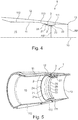
- the trim ring 2 is rotationally symmetrical with respect to the machine axis 10 (cf. Figure 4 ) of the turbofan engine. It comprises a front edge 24, a rear edge 25, an outer side 27 which faces the inner wall 11, and an inner side 28. In the axial direction, it forms three adjacent regions one behind the other in the direction of flow: an upstream region 21 which is conically shaped and converges in the direction of flow, a cylindrical region 22, the diameter of which is constant over its axial length, and a divergent region 23, which is conical and diverges in the direction of flow. Towards the cylindrical region 22, the upstream conical region 21 forms a transition region 21a in which the conical region 21 merges into the cylindrical region 22 and in which it is curved accordingly.
- the thrust nozzle 1 forms a nozzle outlet surface A9 at the outlet edge 13.
- the cladding ring 2 forms a smallest cross-sectional area A81 in the cylindrical region 22.
- the cladding ring has a convex bulge and forms its smallest cross-sectional area in the region of the bulge.
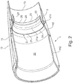
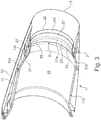
- the thruster 1 is in the Figures 2 and 3rd shown in the second, downstream or axially rear position. In this position, the upstream front edge 24 of the trim ring 2 lies against the downstream end of the conical region 110 of the inner wall 11. This is a bypass channel 3, which is in the position of the Figures 2 to 4 extends behind the front edge 24 between the outside 27 of the trim ring 2 and the inner wall 11, closed.
- the entire flow in the flow channel 15 flows through the cross-sectional area formed by the cladding ring 2, the cladding ring 2 according to FIG Figure 4 forms the cross-sectional area A81 as the smallest cross-sectional area. Accordingly, the smallest cross-sectional area A81 of the trim ring in the axially rearward position is identical to the smallest cross-sectional area of the flow channel 15, that is to say the nozzle neck area.
- the bypass channel 3 Due to the axial displacement of the trim ring 2 in the axially forward position, the bypass channel 3 is released. It opens successively with the displacement of the trim ring 2 in the upstream direction.
- the front edge 24 of the trim ring 2 is removed from the inner wall 11, the front edge forms a flow edge which divides the flow in the flow channel 15 into a flow through the interior of the trim ring 2 and a flow through the bypass channel 3.
- the bypass channel 3 is ring-shaped and preferably also rotationally symmetrical with respect to the machine axis 10 of the turbofan engine.
- the taper of the upstream region 21 of the cladding ring 2 and the taper of the conical region 110 of the inner wall 11 are formed in the same way, so that the cladding ring 2 and the inner wall 11 in the Regions 21, 111 run essentially parallel.
- the bypass channel 3 has a substantially constant cross-sectional area at least at its entrance, so that a flow that is as laminar as possible can be formed.
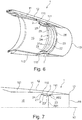
- the bypass channel converges behind the input section of the bypass channel 3 3 slightly and forms a narrowest cross-sectional area A82 of the bypass channel 3, cf. Figure 7 .
- the narrowest cross-sectional area of the flow channel 15 widens, ie the nozzle neck area is now formed by the sum of the cross-sectional areas A81 and A82.
- the cross-sectional area in the axially forward position of the Figures 5-7 opposite the axially rear position of the Figures 2-4 has increased.
- the nozzle neck area A81, A82 and thus also the ratio of nozzle exit area A9 to nozzle neck area A81, A82 can thus be set via the axial position of the trim ring 2.
- the axial position of the narrowest cross-sectional area A82 of the bypass channel 3 can differ from the axial position of the narrowest cross-sectional area A81 of the cladding ring 2, as is shown in FIG Figure 7 is shown. However, this is not necessarily the case.
- the trim ring 2 consists, for example, of a metallic or a ceramic material. It is formed in one piece.
- the cladding ring can consist of several partial rings which correspond, for example, to the different regions 21, 20, 23, the partial rings being separately displaceable.
- the trim ring 2 is axially displaced via a linear adjustment.
- the trim ring 2 has arms projecting radially outward through the bypass channel, which are fastened to a slide or the like which is mounted in the inner wall 11 and can be displaced in the longitudinal direction on a rail.
- the designation "cladding ring” used for the ring 2 takes into account the fact that the ring forms the outer edge of the flow channel 15 in the second position and is therefore part of the cladding of the flow channel.
- the trim ring can be referred to as an adjusting ring or as an annular deflector.
- the term “deflector” is applicable in that the ring divides the flow in all positions except the second position and separates it into a flow through the ring and a flow through the bypass channel.
- the thrust nozzle is two-dimensional and accordingly has an inner wall which delimits the flow channel through the thrust nozzle radially on the outside and which is rectangular in cross section.
- the cladding ring can also be rectangular in cross section in this case. The cladding ring and the individual walls interact to adjust the nozzle neck surface depending on the axial position of the cladding ring, in a manner corresponding to that in relation to a rotationally symmetrical thrust nozzle based on FIG Figures 1 to 7 described.
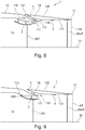
- the Figures 8 to 11 each show in longitudinal section a further embodiment of the invention with an axially displaceable trim ring 2.
- the displaceability of the trim ring 2 is as in relation to the Figures 1-7 executed, to which additional reference is made.
- the peculiarity of the embodiment of the Figures 8-11 is that the thrust nozzle 1 forms at its downstream end - downstream of the nozzle neck surface - a displaceable ring 14 which is also displaceable in the axial direction between a first, upstream position and a second, downstream position.
- This displaceable ring 14 is also referred to below as the nozzle outlet ring 14.
- Via the nozzle exit ring 14, a flow 5 can optionally be switched on, which runs on the outer edge of the flow channel and through which the effective nozzle exit area A9 eff at the end of the thrust nozzle can be reduced and adjusted.
- the thrust nozzle 1 according to FIG Figure 10 an inner wall 11 and an outer wall 12.
- the inner wall 11 forms a converging area 110 and an adjoining cylindrical (or alternatively divergent) area 111.
- a corresponding to the Figures 1 to 7 trained cladding ring 2 is arranged axially displaceable, wherein in the axial position Figure 8 a bypass channel 3, which provides an additional cross-sectional area A82, opened to the maximum Figure 10 closed and in the Figures 9 and 11 is partially open.
- the embodiment of the differs Figures 8 to 11 not from the embodiment of Figures 1 to 7 .
- the downstream region of the thrust nozzle 1 is in the embodiment of the Figures 8 to 11 but not formed by fixed walls, as is the case with the Figures 1 to 7 the case is, but comprises an axially displaceable nozzle outlet ring 14.
- the ring 14 is here via actuators, not shown, between an upstream position, which in the Figure 11 and a downstream position shown in the Figure 9 is shown, displaceable. In the Figures 8 and 10th it is shown in an intermediate position.
- the ring 14 comprises an outer wall 120 and an inner wall 113.
- the outer wall 120 and the inner wall 113 converge downstream and form the nozzle exit edge 13 of the thruster nozzle 1.
- the inner wall 113 forms the extension of the inner wall 111 since it has the flow channel 15 at the rear end edge of the thrust nozzle radially on the outside. Unless the ring 14 is in the upstream position corresponding to the Figure 11 located, it releases an annular additional flow channel 4, via which air is conducted from the outside of the engine into the flow channel 15.
- the additional flow channel 4 is according to the Figure 8 formed by wall regions 121, 113a, which are axially spaced apart, the wall region 113a further downstream than wall region 113 forming the inner wall of the flow channel 15.
- the additional flow channel 4 extends in an annular manner and is designed such that it runs essentially in the axial direction at its end 150 facing the flow channel 15. It opens to the flow channel 15 behind an edge 115, which form the tapered walls 111, 121. In a way, there is a transition to the flow channel 15.
- the curvature of the additional flow channel 4 thus runs such that the axial component of the extension direction towards the end 150 of the additional flow channel 4 becomes larger and the radial component smaller, the radial component at the end 150 of the additional flow channel 4 being zero or low Values.
- the flow 5 flows at least approximately in the axial direction into the flow channel 15 and thus flows in an outer edge region which abuts the inner wall 113 of the nozzle outlet ring 14. It is thereby achieved that the flow flowing through the flow channel 5 does not generate any major turbulence. Since it forms an edge flow adjacent to the inner wall 113, it prevents the flow of the flow channel 15, which has passed through the nozzle neck A81, A82, from flowing up to the inner wall 113. As a result, the geometric nozzle exit area A9, which is defined by the exit edge 13, is reduced to an effective nozzle exit area A9 eff that is smaller than the geometric nozzle exit area A9.
- the effective nozzle outlet area A9 eff can thus be varied and set via the flow 5 or the additional flow channel 4.
- the actuators used to adjust the ring 14 can be, for example, telescopic hydraulic, pneumatic or electrical actuators which are fastened to the outer wall 12 and the outer wall 120 on the outside of the thrust nozzle.
- the Figure 8 shows the fairing ring 2 and the nozzle outlet ring 14 in axial positions that can be set at the MTO starting thrust.
- the nozzle neck area is maximum by providing the additional cross section A82.
- a flow 5 is provided by the additional flow channel 4, which leads to a reduction in the effective nozzle exit area from the geometric nozzle exit area A9 to A9 eff .
- the Figure 9 shows the thruster in an operating mode, which is present in the subsonic cruise.
- the trim ring 2 is displaced axially downstream, so that the cross-sectional area A82 compared to the position of the Figure 8 is reduced.
- the nozzle outlet ring 14 is shifted maximally downstream, so that the flow 5 through the additional flow channel 4 is maximal and accordingly the effective reduction of the nozzle outlet surface A9 is likewise maximal, A9 eff is therefore minimal.
- the Figure 10 shows the transonic case.
- the cladding ring 2 is displaced maximally downstream, so that the bypass channel 3 is closed.
- the nozzle outlet ring 14 is in an axial position in which the additional flow channel 4 is slightly open.
- the associated flow 5 prevents the flow in the flow channel 15 from extending behind the nozzle neck surface A81 up to the nozzle exit edge 13. There is an approximately reduced effective nozzle exit area A9 eff .
- the cladding ring 2 does not completely close the bypass channel 3 in the downstream position, but rather a small gap 61 remains, via which gas from the flow channel 15 is conducted to a small extent into the bypass channel 3. This can serve to avoid or reduce turbulence behind the trim ring 2.
- This embodiment variant can also in the embodiment of the Figures 1 to 7 be provided.
- the Figure 11 shows the engine in an operating mode that corresponds to a supersonic cruise.
- the position of the trim ring 2 corresponds to that Figure 9 .
- the nozzle outlet ring 14 is now maximally displaced upstream, so that the additional flow channel 4 is closed.
- Behind the nozzle neck surface A81, A82, the flow in the flow channel 15 now expands to the nozzle outlet edge 13.
- the structural nozzle outlet surface A9 is identical to the effective nozzle outlet surface A9 eff .
- the nozzle outlet ring 14 in the upstream position does not completely close the additional flow channel 4, but rather a small gap 62 remains, via which air is conducted to a small extent into the additional flow channel 4. This can serve to avoid or reduce turbulence.
- the described variation of the effective nozzle outlet surface can be realized by providing an additional flow by means of an axially displaceable nozzle outlet ring 14 and an additional flow channel 4 with a flow 5 that is optionally released by it, regardless of whether the thrust nozzle has an axially displaceable one Fairing ring 2 or not.
- Such setting and regulation of the effective nozzle outlet area A9 eff can rather also be realized with other thrusters, for example also with iris / petal thrusters according to the prior art.
- the design of the present invention is not limited to the exemplary embodiments described above, which are only to be understood as examples.
- the specific shape and the axial length of the trim ring and the inner wall are only to be understood as examples.
Landscapes
- Engineering & Computer Science (AREA)
- Chemical & Material Sciences (AREA)
- Combustion & Propulsion (AREA)
- Mechanical Engineering (AREA)
- General Engineering & Computer Science (AREA)
- Aviation & Aerospace Engineering (AREA)
- Jet Pumps And Other Pumps (AREA)
- Structures Of Non-Positive Displacement Pumps (AREA)
- Turbine Rotor Nozzle Sealing (AREA)
- Supercharger (AREA)
Description
- Die Erfindung betrifft eine konvergent-divergente Schubdüse für ein Turbofan-Triebwerk eines Überschallflugzeugs gemäß dem Oberbegriff des Patentanspruchs 1 und ein Verfahren zur Einstellung der Düsenhalsfläche in einer Schubdüse eines Turbofan-Triebwerks.
- Es ist allgemein anzustreben, bei einer konvergent-divergenten Schubdüse, die eine Düsenhalsfläche (üblicherweise als A8 bezeichnet) und eine Düsenaustrittsfläche (üblicherweise als A9 bezeichnet) aufweist, den Expansionsgrad des Strömungskanals hinter der Düsenhalsfläche, also das Verhältnis von A9 zu A8 für verschiedene Betriebszustände in gewünschter Weise einstellen zu können.
- Hierzu ist es bekannt, eine Schubdüse mit variabler Kontur auszubilden, beispielsweise als Iris/Petal-Düse mit einer Vielzahl einzelner verstellbarer Lamellen. So ist es bekannt, bei einer Schubdüse eine Gruppe konvergenter Lamellen und eine Gruppe divergenter Lamellen vorzusehen, die jeweils kreisförmig angeordnet sind. Die einzelnen Lamellen sind für ihre Verstellbarkeit mit Aktoren versehen. Eine solche Schubdüse ist beispielsweise aus der
US 9 464 594 B2 - Aus der
EP 2 966 267 A1 ist eine Schubdüsenanordnung bekannt, bei der eine Gasturbine separate Schubdüsen für den Nebenstromkanal, den Primärstromkanal und für einen Mischer aufweist. Dem Mischer ist dabei ein axial verschiebbarer Verkleidungsring zugeordnet, dessen axiale Position den Austrittsquerschnitt der dem Mischer zugeordneten Schubdüse verändert. - Im Kampfflugzeug Messerschmidt 262 war ein Triebwerk realisiert, das eine Schubdüse mit einem Zentralkörper umfasste, der zur Einstellung der Düsenaustrittsfläche axial verstellbar war.
- Die
US 3 598 318 A beschreibt ein Turbofantriebwerk mit einer gattungsgemäßen konvergent-divergenten Schubdüse, die zwischen einem Zentralkörper und einer Gehäusewand ausgebildet ist. An dem Zentralkörper sind verschwenkbare Klappen angeordnet. In einer ersten Position erstrecken diese sich im Inneren der Schubdüse und bilden dabei eine ringförmige Struktur. Sie dienen in der ersten Position dazu, den Gasstrom in der Schubdüse in einen inneren und einen äußeren Bereich aufzuteilen. In einer zweiten Position liegen die Klappen am Zentralkörper an. In einer dritten Position sind die Klappen derart aufgestellt, dass sie den Gasstrom in der Schubdüse blockieren. - Aus der
US 2012/0128467 A1 ist ein Turbofantriebwerk bekannt, bei dem stromaufwärts einer Schubdüse die Luftströmung in einem Bypasskanal über eine Klappenanordnung in zwei Teilströme aufgeteilt wird. Dabei sind im Bypasskanal innere Verkleidungselemente und äußere Verkleidungselemente sowie eine verschiebbare Klappe vorgesehen. Durch Verschieben sämtlicher dieser Elemente können die Querschnittsflächen, über die der Luftstrom im Bypasskanals in zwei Teilströme aufgeteilt wird, variiert werden. Die Klappenanordnung dient als Durchflussbegrenzer. - Der vorliegenden Erfindung liegt die Aufgabe zugrunde, eine für einen Überschallbetrieb geeignete Schubdüse eines Turbofan-Triebwerks sowie ein Verfahren bereitzustellen, die es in effizienter Weise ermöglichen, die Düsenhalsfläche einzustellen.
- Diese Aufgabe wird durch eine Schubdüse mit den Merkmalen des Patentanspruchs 1 und ein Verfahren mit den Merkmalen des Patentanspruchs 13 gelöst. Ausgestaltungen der Erfindung sind in den Unteransprüchen angegeben.
- Danach sieht die vorliegende Erfindung gemäß einem Erfindungsaspekt vor, in einer konvergent-divergenten Schubdüse einen zwischen einer ersten Position und einer zweiten Position in axialer Richtung verschiebbaren Verkleidungsring bereitzustellen. Die Innenwand der Schubdüse und der Verkleidungsring sind derart ausgebildet und zueinander positioniert, dass der Verkleidungsring in der ersten Position radial beanstandet und dabei radial innen zur Innenwand verläuft, wobei ein ringförmiger Bypass-Kanal bereitgestellt wird, der zwischen dem Verkleidungsring und der Innenwand der Schubdüse verläuft. In der zweiten Position liegt der Verkleidungsring dagegen an der Innenwand an, so das der Bypass-Kanal verschlossen ist bzw. ein solcher effektiv nicht mehr existiert. Als Düsenhalsfläche wird dabei die engste Querschnittsfläche des Strömungskanals und als Düsenaustrittsfläche die Querschnittsfläche des Strömungskanals am hinteren Ende der Schubdüse bezeichnet.
- Dabei stellt der Bypass-Kanal eine zusätzliche Querschnittsfläche des Strömungskanals bereit. Der Bypass-Kanal wird in der ersten Position dadurch gebildet, dass der Verkleidungsring über seine gesamte Länge radial beabstandet und dabei radial innen zur Innenwand verläuft. Der Bereich zwischen dem Verkleidungsring und der Innenwand bildet den Bypass-Kanal.
- Die Erfindung beruht somit auf dem Gedanken, die Düsenhalsfläche mittels eines in axialer Richtung verstellbaren Verkleidungsrings zu variieren, wobei abhängig von der axialen Stellung des Verkleidungsrings ein Bypass-Kanal eine zusätzliche Querschnittsfläche, die zur Düsenhalsfläche beiträgt, bereitstellt. Insbesondere wird in der ersten Position, d.h. der einen Extremposition des Verkleidungsrings die Düsenhalsfläche durch die Summe der kleinsten Querschnittsfläche des Verkleidungsrings und der kleinsten Querschnittsfläche des Bypass-Kanals gebildet. In der zweiten Position, d.h. der anderen Extremposition wird die Düsenhalsfläche dagegen allein durch die engste Querschnittsfläche des Verkleidungsrings gebildet. Während der axialen Bewegung des Verkleidungsrings von der ersten Position in die zweite Position reduziert sich dabei die durch den Bypass-Kanal bereitgestellte zusätzliche Querschnittsfläche, bis sie in der zweiten Position bei null liegt. Umgekehrt öffnet sich sukzessive der Bypass-Kanal, wenn der Verkleidungsring von der zweiten Position in Richtung der ersten Position verschoben wird und er sich dabei von der Innenwand der Schubdüse entfernt. Der Verkleidungsring kann dabei eine, mehrere oder beliebig viele axiale Positionen zwischen der ersten Position und der zweiten Position einnehmen, d.h. er ist nicht darauf beschränkt, sich in der ersten oder zweiten Position zu befinden. Hierdurch kann die durch den Bypass-Kanal bereitgestellte zusätzliche Querschnittsfläche feinstufig eingestellt werden.
- Die vorliegende Erfindung ermöglicht damit eine Einstellung des Expansionsgrads des Strömungskanals hinter der Düsenhalsfläche bzw. des Verhältnisses von Düsenaustrittsfläche zu Düsenhalsfläche, indem bei feststehender Düsenaustrittsfläche die Düsenhalsfläche variiert wird.
- Die Erfindung ermöglicht dabei die Einstellung des Expansionsgrads ohne die Notwendigkeit, die Innenwand der Schubdüse, die die radial äußere Berandung des Strömungskanals in der Schubdüse darstellt, verstellbar ausgestalten zu müssen. Eine Änderung der Düsenhalsfläche wird durch eine axiale Verschiebung des Verkleidungsrings und eine damit verbundene Bereitstellung einer zusätzlichen Querschnittsfläche, die zur Düsenhalsfläche beiträgt, in einem Bypass-Kanal erreicht. Damit entfällt eine ansonsten erforderliche aufwendige und gewichtsintensive Ausbildung der Schubdüse als Schubdüse mit variabler Kontur, beispielsweise als Iris/Petal-Düse mit einer Vielzahl einzelner verstellbarer Lamellen, so dass Komplexität und Gewicht der Schubdüse durch die Erfindung reduziert sind. Ein weiterer Vorteil besteht darin, dass mit dem Wegfall von Lamellen zur Bildung der Innenwand der Schubdüse eine glatte äußere Berandung des Strömungskanals durch die Schubdüse bereitgestellt werden kann.
- Eine Ausgestaltung der Erfindung sieht vor, dass die erste Position eine stromaufwärtige Position und die zweite Position eine stromabwärtige Position ist, wobei der Bypass-Kanal in der stromaufwärtigen Position zwischen dem Verkleidungsring und der Innenwand der Schubdüse ausbildet ist und in der stromabwärtigen Position der Verkleidungsring an der Innenwand anliegt. Die stromaufwärtige Position wird auch als ausgefahrene Position und die stromaufwärtige Position auch als Stauposition bezeichnet, da in letzterer der Verkleidungsring an der Innenwand der Schubdüse anliegt.
- Gemäß einer Ausgestaltung der Erfindung weist der Verkleidungsring einen stromaufwärtigen Bereich auf, der in Strömungsrichtung konvergiert. Insbesondere kann vorgesehen sein, dass der Verkleidungsring in seinem stromaufwärtigen Bereich konisch ausgebildet ist, mit einer in Strömungsrichtung konvergierenden Querschnittsfläche. An den stromaufwärtigen Bereich schließt sich stromabwärts ein zylindrischer Bereich und/oder ein in Strömungsrichtung divergenter Bereich an. Im - sofern vorhanden - zylindrischen Bereich oder alternativ im Übergang vom stromaufwärtigen Bereich zum divergenten stromabwärtigen Bereich weist der Verkleidungsring somit ein Minimum seiner Querschnittsfläche auf. Dabei kann vorgesehen sein, dass der Verkleidungsring im Bereich seines Minimums eine Ausbuchtung aufweist.
- Gemäß einer Ausgestaltung weist der Verkleidungsring angrenzend an den stromaufwärtigen Bereich einen zylindrischen Bereich und angrenzend an den zylindrischen Bereich einen stromabwärtigen Bereich auf, wobei letzterer in Strömungsrichtung divergiert. Der Verkleidungsring besteht somit gemäß dieser Ausführungsvariante aus drei axial aufeinanderfolgenden Bereichen, einem konvergenten Bereich, einem zylindrischen Bereich und einem divergenten Bereich.
- Die Innenwand der Schubdüse bildet ebenfalls einen konvergente Bereich aus, in dem die Querschnittsfläche der Innenwand in Strömungsrichtung konvergiert. In dem konvergenten Bereich ist die Innenwand der Schubdüse beispielsweise konisch ausgebildet. Stromabwärts des konvergenten Bereichs bildet die Innenwand einen zylindrischen und/oder einen divergenten Bereich aus.
- Dabei ist vorgesehen, dass der stromaufwärtige Bereich des Verkleidungsrings, der in Strömungsrichtung konvergiert, und der konvergente Bereich der Innenwand sich zumindest teilweise über den gleichen axialen Bereich der Schubdüse erstrecken, wenn der Verkleidungsring sich in der ersten Position befindet. Eine Ausgestaltung hierzu sieht vor, dass der stromaufwärtigen Bereich des Verkleidungsrings und der konvergente Bereich der Innenwand im Wesentlichen parallel zueinander verlaufen, wenn der Verkleidungsring sich in der ersten Position befindet. Hierdurch wird ein Bypass-Kanal im wesentlichen konstanten Querschnitts bereitgestellt, in dem die Strömung verlustarm strömen kann.
- Eine weitere Ausgestaltung sieht vor, dass die stromaufwärtige Kante des stromaufwärtigen Bereichs des Verkleidungsrings in der zweiten Position an der Innenwand der Schubdüse anliegt. Der Verkleidungsring liegt somit in der zweiten Position entlang einer Umfangslinie an der Innenwand an. Die Umfangslinie liegt dabei in einer Ebene, die senkrecht zur axialen Richtung bzw. zur Maschinenachse verläuft. Das Anliegen des Verkleidungsrings in der zweiten Position entlang einer Umfangslinie an der Innenwand stellt jedoch nur ein Ausführungsbeispiel dar. Grundsätzlich kann der Verkleidungsring in der zweiten Position auch entlang einer Umfangsfläche an der Innenwand anliegen. Dies hängt von der genauen Formgebung von Verkleidungsring und Innenwand ab.
- Eine Ausgestaltung sieht vor, dass die Vorderkante des stromaufwärtigen Bereichs des Verkleidungsrings im konvergenten Bereich der Innenwand oder am Übergang des konvergenten Bereichs zu einem sich daran stromabwärts anschließenden zylindrischen oder divergenten Bereich an der Innenwand der Schubdüse anliegt.
- Gemäß einer Ausgestaltung der Erfindung ist die Innenwand der Schubdüse, die die radial äußere Berandung des Strömungskanals in der Schubdüse bildet, nicht verstellbar ausgebildet. Wie bereits erläutert, wird eine Änderung der Düsenhalsfläche durch axiales Verschieben des Verkleidungsrings erreicht. Damit entfällt eine ansonsten erforderliche, jedoch aufwendige und gewichtsintensive Ausbildung der Schubdüse als Schubdüse mit variabler Kontur. Gleichwohl wird darauf hingewiesen, dass grundsätzlich ein axial verschiebbarer Verkleidungsring auch mit einer variablen oder teilweise variablen Außenkontur der Schubdüse kombiniert werden kann.
- Die Schubdüse kann als dreidimensionale Schubdüse oder als zweidimensionale Schubdüse ausgebildet sein. Im Falle einer dreidimensionalen Schubdüse weist deren Innenwand einen kreisförmigen Querschnitt auf. Der Verkleidungsring ist dementsprechend als kreisförmiger Ring ausgebildet, der in Hinblick auf die Maschinenachse des Turbofan-Triebwerks rotationssymmetrisch ausgebildet ist. Im Falle einer zweidimensionalen Schubdüse ist deren Innenwand im Querschnitt rechteckförmig ausgebildet. Der Verkleidungsring kann in diesem Fall ebenfalls im Querschnitt rechteckförmig ausgebildet sein (mit Abrundungen an den Kanten).
- Eine Ausgestaltung der Erfindung sieht vor, dass sowohl die Innenwand und die Außenwand des Verkleidungsrings als auch die Innenwand der Schubdüse im mathematischen Sinne glatt ausgebildet, also nicht mit Kanten versehen sind.
- Der Verkleidungsring der vorliegenden Erfindung ist gemäß einer Ausgestaltung einteilig ausgebildet. Er besteht beispielsweise aus einem metallischen oder einem keramischen
- Material. Grundsätzlich ist es jedoch alternativ möglich, dass der Ring aus einer Mehrzahl von Teilringen besteht, die jeweils axial verschiebbar sind.
- Gemäß einer Ausgestaltung der Erfindung weist die Schubdüse keinen Zentralkörper auf, der sich entlang der Maschinenachse des Turbofan-Triebwerks erstreckt. Ein solcher Zentralkörper ist nicht erforderlich.
- Gemäß einer Ausgestaltung ist eine konvergent-divergente Schubdüse für ein Turbofan-Triebwerk eines Überschallflugzeugs vorgesehen, die aufweist:
- eine Innenwand, die einen Strömungskanal durch die Schubdüse radial außen begrenzt, wobei der Strömungskanal eine Düsenhalsfläche und eine Düsenaustrittsfläche ausbildet, und
- einen zwischen einer ersten Position und einer zweiten Position in axialer Richtung verschiebbaren Verkleidungsring, wobei
- die Innenwand der Schubdüse und der Verkleidungsring derart ausgebildet und zueinander positioniert sind, dass der Verkleidungsring in der ersten Position radial beabstandet zur Innenwand verläuft, wobei ein ringförmiger Bypass-Kanal bereitgestellt ist, der zwischen dem Verkleidungsring und der Innenwand der Schubdüse verläuft, und der Verkleidungsring in der zweiten Position an der Innenwand anliegt,
- der Verkleidungsring einen stromaufwärtigen Bereich aufweist, der in Strömungsrichtung konvergiert, wobei sich an den stromaufwärtigen Bereich stromabwärts ein zylindrischer Bereich und/oder ein in Strömungsrichtung divergierender Bereich anschließt,
- die Innenwand der Schubdüse einen konvergenten Bereich ausbildet, in dem die Querschnittsfläche der Innenwand in Strömungsrichtung konvergiert, und
- die stromaufwärtige Kante des stromaufwärtigen Bereichs des Verkleidungsrings in der zweiten Position an der Innenwand der Schubdüse anliegt.
- In einem weiteren Erfindungsaspekt betrifft die Erfindung eine Schubdüse für ein Turbofan-Triebwerk eines Überschallflugzeugs, wobei die Schubdüse einen Strömungskanal mit einer Düsenaustrittsfläche ausbildet. Es ist vorgesehen, dass die Schubdüse an ihrem stromabwärtigen Ende einen zwischen einer ersten, stromaufwärtigen Position und einer zweiten, stromabwärtigen Position in axialer Richtung verschiebbaren Düsenaustrittsring ausbildet. Dabei bildet die Schubdüse in der zweiten Position des Düsenaustrittsrings einen ringförmigen Zusatz-Strömungskanal aus, der sich von der Außenhaut der Schubdüse zum Strömungskanal erstreckt und über den Umgebungsluft in den Strömungskanal strömen kann. Der Zusatz-Strömungskanal ist dabei zwischen dem stromaufwärtigen Ende des Düsenaustrittsrings und daran sich stromaufwärts anschließenden Wandbereichen der Schubdüse ausgebildet.
- In der ersten Position des Düsenaustrittsrings ist der ringförmige Zusatz-Strömungskanal dagegen geschlossen. Zwischen der ersten und der zweiten Position des Düsenaustrittsrings vergrößert sich die Querschnittsfläche des Zusatz-Strömungskanals sukzessive. Dabei kann vorgesehen sein, dass der Düsenaustrittsring entsprechende Zwischenpositionen einnehmen kann. Der Zusatz-Strömungskanal ist derart ausgebildet und geformt ist, dass die aus dem Zusatz-Strömungskanal austretende Luft eine radial äußere Randströmung im Strömungskanal bildet.
- Hierdurch erreicht die Erfindung gemäß diesem Erfindungsaspekt eine effektive Reduzierung der Düsenaustrittsfläche für das im Strömungskanal der Schubdüse strömende Gas (das zuvor die Düsenhalsfläche passiert hat). Denn die durch den Zusatz-Strömungskanal einströmende Luft legt sich als Randströmung an die äußere Berandung des Strömungskanals, so dass das im Strömungskanal strömende Gas nicht bis an die äußere Berandung des Strömungskanals strömt. Damit wird indirekt die Düsenaustrittsfläche von der geometrischen Düsenaustrittsfläche auf eine effektive Düsenaustrittsfläche reduziert. Über die axiale Stellung des Düsenaustrittsrings kann somit die effektive Düsenaustrittsfläche eingestellt werden.
- Eine Ausgestaltung sieht vor, der Düsenaustrittsring eine an die Umgebung angrenzende Außenwand und eine den Strömungskanal begrenzende Innenwand ausbildet und der Zusatz-Strömungskanal derart ausgebildet und geformt ist, dass er an seinem stromabwärtigen, dem Strömungskanal zugewandten Ende im Wesentlichen in axialer Richtung verläuft, so dass die aus dem Zusatz-Strömungskanal austretende Luft eine Randströmung bildet, die entlang der Innenwand des Düsenaustrittsrings und unmittelbar angrenzend an diese verläuft. Hierdurch wird sichergestellt, dass die Strömung des Zusatz-Strömungskanals eine Randströmung am Ausgang der Schubdüse bildet.
- Eine weitere Ausgestaltung sieht vor, dass die Schubdüse eine konvergent-divergente oder eine konvergent-zylindrische Schubdüse ist und die Schubdüse derart ausgebildet ist, dass das stromabwärtige Ende des Zusatz-Strömungskanals sich stromabwärts des Düsenhalsfläche der Schubdüse befindet.
- Der Zusatz-Strömungskanal ist dabei derart gekrümmt, dass seine radiale Erstreckungskomponente stromabwärts abnimmt und seine axiale Erstreckungskomponente stromabwärts zunimmt.
- Der erläuterte Erfindungsaspekt eines in axialer Richtung verschiebbaren Düsenaustrittsrings wird gemäß einer Ausgestaltung bei einer Schubdüse realisiert, die einen gemäß Patentanspruch 1 axial verschiebbaren Verkleidungsring aufweist. Dies ist aber nicht notwendigerweise der Fall. So kann ein in axialer Richtung verschiebbarer Düsenaustrittsring grundsätzlich bei beliebigen Schubdüsen eingesetzt werden, um die effektive Düsenhalsfläche einstellen zu können, beispielsweise auch bei Schubdüsen in Iris/Petal-Ausführung. Bei der Schubdüse, die einen axial verschiebbaren Verkleidungsring aufweist, kann es sich grundsätzlich um eine konvergent-divergente Schubdüse, eine konvergent-zylindrische Schubdüse oder eine nur konvergente Schubdüse handeln. Die Schubdüse kann als dreidimensionale Schubdüse oder als zweidimensionale Schubdüse ausgebildet sein.
- Gemäß einem weiteren Erfindungsaspekt betrifft die Erfindung ein Verfahren zur Einstellung der Düsenhalsfläche in einer Schubdüse eines Turbofan-Triebwerks eines Überschallflugzeugs. Das Verfahren umfasst die Schritte:
- Bereitstellen eines zwischen einer ersten Position und einer zweiten Position in axialer Richtung verschiebbaren Verkleidungsrings, der in der ersten Position unter Ausbildung eines Bypass-Kanals radial beabstandet und dabei radial innen zur Innenwand verläuft und der in der zweiten Position an der Innenwand anliegt, wobei der Bypass-Kanal in der zweiten Position geschlossen ist, und
- Verschieben des Verkleidungsrings zwischen der ersten Position und der zweiten Position zur Einstellung der gewünschten kleinsten Querschnittsfläche des Bypass-Kanals, wobei
- in der ersten Position die Düsenhalsfläche durch die Summe der kleinsten Querschnittsfläche des Verkleidungsrings und der kleinsten Querschnittsfläche des Bypass-Kanals gebildet ist, und
- in der zweiten Position die Düsenhalsfläche durch die engste Querschnittsfläche des Verkleidungsrings gebildet ist.
- Dabei wird zur Einstellung einer maximalen Düsenhalsfläche der Verkleidungsring in eine maximal stromaufwärtigen Position als erste Position verschoben. Zur Einstellung einer minimalen Düsenhalsfläche wird der Verkleidungsring in eine maximal stromabwärtige Position als zweite Position verschoben. Zur Einstellung einer Düsenhalsfläche, die zwischen der maximalen und der minimalen Düsenhalsfläche liegt, wird der Verkleidungsring in eine Position verschoben, die zwischen der maximal stromaufwärtigen und der maximal stromabwärtigen Position liegt.
- Es wird darauf hingewiesen, dass die vorliegende Erfindung bezogen auf ein zylindrisches Koordinatensystem beschrieben ist, das die Koordinaten x, r und ϕ aufweist. Dabei gibt x die axiale Richtung, r die radiale Richtung und ϕ den Winkel in Umfangsrichtung an. Die axiale Richtung ist dabei identisch mit der Maschinenachse des Turbofan-Triebwerks. Von der x-Achse ausgehend zeigt die radiale Richtung radial nach außen. Begriffe wie "vor", "hinter", "vordere" und "hintere" beziehen sich immer auf die axiale Richtung bzw. die Strömungsrichtung im Triebwerk. Die Bezeichnung "vor" bedeutet somit "stromaufwärts" und die Bezeichnung "hinter" bedeutet "stromabwärts". Begriffe wie "äußere" oder "innere" beziehen sich immer auf die radiale Richtung.
- Die Erfindung kann in einem Turbofan-Triebwerk mit einer Schubdüse gemäß Anspruch 1 und einem zivilen oder militärischen Überschallflugzeug mit einem solchen Turbofan-Triebwerk eingesetzt werden.
- Die Erfindung wird nachfolgend unter Bezugnahme auf die Figuren der Zeichnung anhand mehrerer Ausführungsbeispiele näher erläutert. Es zeigen:
- Figur 1
- ein Ausführungsbeispiel einer Schubdüse eines Turbofan-Triebwerks, das für einen Überschallflug vorgesehen und ausgebildet ist, wobei die Schubdüse einen axial verschiebbaren Verkleidungsring aufweist und der Verkleidungsring in zwei axial beanstandeten Positionen dargestellt ist;
- Figur 2
- die Schubdüse der
Figur 1 in einer perspektivischen, geschnittenen Ansicht schräg von vorne, wobei die Schubdüse in einer axial hinteren Position angeordnet ist; - Figur 3
- die Schubdüse der
Figur 1 in einer perspektivischen, geschnittenen Ansicht schräg von hinten, wobei die Schubdüse in einer axial hinteren Position angeordnet ist; - Figur 4
- einen Längsschnitt durch die Schubdüse der
Figur 1 , wobei die Schubdüse in einer axial hinteren Position entsprechend denFiguren 2 und3 angeordnet ist; - Figur 5
- die Schubdüse der
Figur 1 in einer perspektivischen, geschnittenen Ansicht schräg von vorne, wobei die Schubdüse in einer axial vorderen Position angeordnet ist; - Figur 6
- die Schubdüse der
Figur 1 in einer perspektivischen, geschnittenen Ansicht schräg von hinten, wobei die Schubdüse in einer axial vorderen Position angeordnet ist; - Figur 7
- einen Längsschnitt durch die Schubdüse der
Figur 1 , wobei die Schubdüse in einer axial vorderen Position entsprechend denFiguren 5 und6 angeordnet ist; - Figur 8
- im Längsschnitt ein weiteres Ausführungsbeispiel einer Schubdüse mit einem in axialer Richtung verschiebbaren Verkleidungsring, wobei die Schubdüse des Weiteren an ihrem stromabwärtigen Ende einen axial verschiebbaren Düsenaustrittsring ausbildet;
- Figur 9
- die Schubdüse der
Figur 8 mit anderen axialen Positionen von Verkleidungsring und Düsenaustrittsring; - Figur 10
- die Schubdüse der
Figur 8 mit anderen axialen Positionen von Verkleidungsring und Düsenaustrittsring; und - Figur 11
- die Schubdüse der
Figur 8 mit anderen axialen Positionen von Verkleidungsring und Düsenaustrittsring. - Die
Figur 1 zeigt eine konvergent-divergente Schubdüse 1 eines Turbofan-Triebwerks, das dafür vorgesehen und geeignet ist, in einem zivilen oder militärischen Überschallflugzeug eingesetzt zu werden und dementsprechend für Betriebszustände im subsonischen Bereich, im transsonischen Bereich und im supersonischen Bereich ausgelegt ist. - Das Turbofan-Triebwerk umfasst in an sich bekannter Weise einen Triebwerkseinlauf, einen Fan, der mehrstufig ausgebildet sein kann, einen Primärstromkanal, der durch ein Kerntriebwerk führt und einen Sekundärstromkanal oder Bypass-Kanal, der an dem Kerntriebwerk vorbei führt. Des Weiteren ist ein Mischer vorgesehen, der Luft des Sekundärstromkanals und des Primärstromkanals hinter dem Kerntriebwerk mischt. Hinter dem Mischer bildet das Triebwerk einen Strömungskanal, der sich durch die Schubdüse erstreckt. Optional können zusätzlich ein Nachbrenner und/oder ein Schubumkehrer vorgesehen sein.
- Der Triebwerkseinlauf bildet einen Überschall-Lufteinlauf und ist dementsprechend dafür vorgesehen und geeignet, die einströmende Luft auf Geschwindigkeiten unterhalb Ma 1,0 (Ma = Mach-Zahl) zu verzögern. Der Triebwerkseinlauf kann angeschrägt ausgebildet sein, um im Überschallflug eine günstige Verdichtungsstosskonfiguration zu erzielen.
- Das Kerntriebwerk weist einen Verdichter, eine Brennkammer und eine Turbine auf. Beispielsweise umfasst der Verdichter einen Hochdruckverdichter und einen Niederdruckverdichter, wobei ein Niederdruckverdichter durch die nabennahen Bereiche des Fans gebildet ist. Die hinter der Brennkammer angeordnete Turbine umfasst eine Hochdruckturbine und eine Niederdruckturbine. Die Hochdruckturbine treibt eine Hochdruckwelle an, die die Hochdruckturbine mit dem Hochdruckverdichter verbindet. Die Niederdruckturbine treibt eine Niederdruckwelle an, die die Niederdruckturbine mit dem Fan verbindet. Gemäß einer alternativen Ausgestaltung kann das Turbofantriebwerk zusätzlich einen Mitteldruckverdichter, eine Mitteldruckturbine und eine Mitteldruckwelle aufweisen.
- Das Turbofan-Triebwerk ist in einer Triebwerksgondel angeordnet. Diese ist beispielsweise über einen Pylon mit dem Flugzeugrumpf verbunden.
- Das Turbofan-Triebwerk umfasst eine Maschinenachse 10 oder Triebwerksmittellinie. Die Maschinenachse definiert eine axiale Richtung des Turbofan-Triebwerks. Eine radiale Richtung des Turbofan-Triebwerks verläuft senkrecht zur axialen Richtung.
- Die
Figur 1 zeigt ein Ausführungsbeispiel einer Schubdüse 1, die einen axial verschiebbaren Verkleidungsring 2 umfasst. DieFigur 1 verdeutlicht dabei unterschiedliche axiale Positionen des Verkleidungsrings 2. Eine genauere Beschreibung des Verkleidungsrings 2 und der mit diesem erzielten Vorteile und Funktionen erfolgt im Hinblick auf dieFiguren 2 bis 7 . - Strukturell wird die Schubdüse 1 durch eine Innenwand 11 und eine Außenwand 12 gebildet. Die Außenwand 12 ist radial außen zur Innenwand 11 ausgebildet und grenzt an die Umgebung an. Die Innenwand 11 bildet die radial äußere Berandung eines Strömungskanals 15 in der Schubdüse 1. Der Strömungskanal 15 befindet sich dabei hinter einem Mischer des Turbofan-Triebwerks, der die Strömung im Primärstromkanal und die Strömung im Sekundärstromkanal des Turbofan-Triebwerks mischt. Die Innenwand 11 und die Außenwand 12 laufen stromabwärts spitz aufeinander zu und bilden an ihrem stromabwärtigen Ende eine Düsenaustrittskante 13.
- Der Verkleidungsring 2 ist in axialer Richtung zwischen einer ersten, stromaufwärtigen bzw. axial vorderen Position und einer zweiten, stromabwärtigen bzw. axial hinteren Position verschiebbar, wobei die
Figur 1 den Verkleidungsring 2 in beiden Positionen zeigt. Abhängig von der axialen Position öffnet oder schließt der Verkleidungsring 2 einen Bypass-Kanal 3, der eine zusätzliche Querschnittsfläche bereitstellt. Hierdurch kann die Düsenhalsfläche des Strömungskanals 15 eingestellt werden. Natürlich kann der Verkleidungsring 2 auch Positionen einnehmen, die zwischen der ersten und der zweiten Position liegen. - Die
Figuren 2 bis 4 zeigen die Schubdüse 1 in detaillierterer Darstellung, wobei dieFiguren 2 und3 perspektivische Darstellungen und dieFigur 3 einen Längsschnitt durch die Maschinenachse 10 darstellen. Wie bereits in Bezug auf dieFigur 1 erläutert, umfasst die Schubdüse eine Innenwand 11, eine Außenwand 12 und einen axial verschiebbaren Verkleidungsring 2. In der Schubdüse 1 verläuft der Strömungskanal 15, der durch die Innenwand 11 begrenzt wird. - Die Innenwand 11 der Schubdüse 1 weist in Strömungsrichtung in einem axial vorderen Abschnitt einen allgemein konvergenten Verlauf auf, d.h. die Querschnittsfläche des Strömungskanals 15, die durch die Innenwand 11 radial außen berandet ist, nimmt in Strömungsrichtung ab. Sie erreicht ihr Minimum am stromabwärtigen Ende eines konisch konvergierenden Bereichs 110 der Innenwand 11. Dabei es nicht zwingend, dass die Querschnittsfläche stetig abfällt. Vielmehr kann, wie dargestellt, ein Zwischenbereich 112 vorgesehen sein, in dem die Querschnittsfläche ansteigt oder alternativ konstant bleibt, bevor die Querschnittsfläche der Innenwand 11 im Bereich 110 zu ihrem Minimum abfällt.
- Stromabwärts des konischen Bereichs 110 bildet die Innenwand 11 einen divergenten Bereich 111 aus, in dem die Querschnittsfläche der Innenwand 11 ansteigt, Der divergente Bereich erstreckt sich bis zur Düsenaustrittskante 13. Alternativ kann statt eines divergenten Bereichs 111 ein zylindrischer Bereich vorgesehen sein oder ein zylindrischer Bereich, an den sich ein divergenter Bereich anschließt.
- Der Verkleidungsring 2 ist rotationssymmetrisch bezüglich der Maschinenachse 10 (vgl.
Figur 4 ) des Turbofan-Triebwerks ausgebildet. Er umfasst eine Vorderkante 24, eine Hinterkante 25, eine Außenseite 27, die der Innenwand 11 zugewandt ist, und eine Innenseite 28. In axialer Richtung bildet er in Strömungsrichtung hintereinander drei aneinander angrenzende Bereiche aus: einen stromaufwärtigen Bereich 21, der konisch geformt ist und in Strömungsrichtung konvergiert, einen zylindrischen Bereich 22, dessen Durchmesser über seine axiale Länge konstant ist, und einen divergenten Bereich 23, der konisch geformt ist und dabei in Strömungsrichtung divergiert. Zum zylindrischen Bereich 22 hin bildet der stromaufwärtige konische Bereich 21 dabei einen Übergangsbereich 21a aus, in dem der konische Bereich 21 in den zylindrischen Bereich 22 übergeht und in dem er dementsprechend gekrümmt ist. - Wie in der
Figur 4 erkennbar, bildet die Schubdüse 1 an der Austrittskante 13 eine Düsenaustrittsfläche A9. - Der Verkleidungsring 2 bildet eine kleinste Querschnittsfläche A81 im zylindrischen Bereich 22 aus. In alternativen Ausgestaltungen kann vorgesehen sein, dass der Verkleidungsring eine konvexe Ausbuchtung aufweist und im Bereich der Ausbuchtung seine kleinste Querschnittsfläche ausbildet.
- Die Schubdüse 1 ist in den
Figuren 2 und3 in der zweiten, stromabwärtigen bzw. axial hinteren Position dargestellt. In dieser Position liegt die stromaufwärtige Vorderkante 24 des Verkleidungsrings 2 am stromabwärtigen Ende des konischen Bereichs 110 der Innenwand 11 an. Hierdurch ist ein Bypass-Kanal 3, der sich in der Position derFiguren 2 bis 4 hinter der Vorderkante 24 zwischen der Außenseite 27 des Verkleidungsrings 2 und der Innenwand 11 erstreckt, geschlossen. - Da der Bypass-Kanal 3 aufgrund der Anordnung des Verkleidungsrings 2 in der axial hinteren Position verschlossen ist, fließt die gesamte Strömung im Strömungskanal 15 durch die durch den Verkleidungsring 2 gebildeten Querschnittsfläche, wobei der Verkleidungsring 2 gemäß der
Figur 4 als kleinste Querschnittsfläche die Querschnittsfläche A81 ausbildet. Dementsprechend ist die kleinste Querschnittsfläche A81 des Verkleidungsrings in der axial hinteren Position identisch mit der kleinsten Querschnittsfläche des Strömungskanals 15, d.h. mit der Düsenhalsfläche. - Diese Situation ändert sich allerdings, wenn der Verkleidungsring 2 stromaufwärts in die axial vordere Position verschoben wird, wie nachfolgend anhand der
Figuren 5-7 erläutert. - Aufgrund der axialen Verschiebung des Verkleidungsrings 2 in die axial vordere Position wird der Bypass-Kanal 3 freigegeben. Er öffnet sich sukzessive mit der Verschiebung des Verkleidungsrings 2 in die stromaufwärtige Richtung. Mit Entfernen der Vorderkante 24 des Verkleidungsrings 2 von der Innenwand 11 bildet die Vorderkante eine Strömungskante, die den Strom im Strömungskanal 15 in einen Strom durch das Innere des Verkleidungsrings 2 und einen Strom durch den Bypass-Kanal 3 aufteilt. Der Bypass-Kanal 3 ist dabei ringförmig und bevorzugt ebenfalls rotationssymmetrisch bezogen auf die Maschinenachse 10 des Turbofan-Triebwerks ausgebildet.
- In dem dargestellten Ausführungsbeispiel, jedoch nicht notwendigerweise, ist dabei vorgesehen, dass die Konizität des stromaufwärtigen Bereichs 21 des Verkleidungsrings 2 und die Konizität des konischen Bereichs 110 der Innenwand 11 in gleicher Weise ausgebildet sind, so dass der Verkleidungsring 2 und die Innenwand 11 in den Bereichen 21, 111 im Wesentlichen parallel verlaufen. Dies ist mit dem Vorteil verbunden, dass der Bypass-Kanal 3 zumindest an seinem Eingang eine im Wesentlichen konstante Querschnittsfläche aufweist, so dass sich eine möglichst laminare Strömung ausbilden kann. Hinter dem Eingangsabschnitt des Bypass-Kanals 3 konvergiert der Bypass-Kanal 3 geringfügig und bildet eine engsten Querschnittsfläche A82 des Bypass-Kanals 3 aus, vgl.
Figur 7 . - Aufgrund dieser zusätzlichen engsten Querschnittsfläche A82 erweitert sich die engste Querschnittsfläche des Strömungskanals 15, d.h. die Düsenhalsfläche wird nunmehr durch die Summe der Querschnittsflächen A81 und A82 gebildet. Dies bedeutet aber, dass die Querschnittsfläche in der axial vorderen Position der
Figuren 5-7 gegenüber der axial hinteren Position derFiguren 2-4 zugenommen hat. Über die axiale Position des Verkleidungsrings 2 kann somit die Düsenhalsfläche A81, A82 und damit auch das Verhältnis von Düsenaustrittsfläche A9 zu Düsenhalsfläche A81, A82 eingestellt werden. - Es wird darauf hingewiesen, dass die axiale Lage der engsten Querschnittsfläche A82 des Bypass-Kanals 3 sich von der axialen Lage der engsten Querschnittsfläche A81 des Verkleidungsrings 2 unterscheiden kann, wie es in der
Figur 7 dargestellt ist. Dies ist jedoch nicht notwendigerweise der Fall. - Hinter dem Verkleidungsring 2 vereinigen sich die Strömung durch den Bypass-Kanal 3 und die Strömung durch den Verkleidungsring 2 wieder zu einer Strömung, vgl.
Figur 7 . Dies kann unter vernachlässigbaren Strömungsverlusten erfolgen, wenn der hintere Bereich 23 des Verkleidungsrings 2 in Strömungsrichtung ausgerichtet ist. - Vor der Düsenhalsfläche ist die Strömungsgeschwindigkeit in der Schubdüse bei allen Betriebsmodi bzw. axialen Positionen des Verkleidungsrings kleiner als Ma=1. An der Düsenhalsfläche gilt, dass Ma=1 ist. Hinter der Düsenhalsfläche A8 ist die Strömungsgeschwindigkeit in der Schubdüse bei allen Betriebsmodi außer dem Betriebsmodus "MTO" (MTO = Maximum Takeoff Thrust) größer als Ma=1.
- Der Verkleidungsring 2 besteht beispielsweise aus einem metallischen oder einem keramischen Material. Er ist einstückig ausgebildet. In alternativen Ausgestaltungen kann der Verkleidungsring aus mehreren Teilringen bestehen, die beispielsweise den verschiedenen Bereichen 21, 20, 23 entsprechen, wobei die Teilringe gesondert verschiebbar sind.
- Zur axialen Verschiebung des Verkleidungsrings 2 in der Schubdüse 1 können verschiedene Verstellmechanismen vorgesehen sein. Gemäß einer ersten Ausgestaltung erfolgt eine Verstellung des Verkleidungsrings 2 über Aktuatoren, die beispielsweise teleskopartig wirkend ausgebildet sind und hydraulisch, pneumatisch oder elektrisch angetrieben werden. Dabei kann vorgesehen sein, dass solche Aktoren entlang des Umfangs jeweils in einem Winkel zueinander angeordnet sind und somit eine fachwerkartige Konstruktion bilden (sogenanntes Thruss Prinzip). Die Aktuatoren sind beispielsweise mit einem Ende an der Innenwand 11 und mit einem oder mehreren anderen Enden an der Außenseite des Verkleidungsrings 2 befestigt. Solche Aktoren sind, wenn auch in anderem Kontext, in der
EP 3 081 797 A1 beschrieben. - Gemäß einer zweiten Ausgestaltung erfolgt eine axiale Verschiebung des Verkleidungsrings 2 über eine Linearverstellung. Beispielsweise weist der Verkleidungsring 2 radial nach außen durch den Bypass-Kanal ragende Arme auf, die an einem in der Innenwand 11 gelagerten, in Längsrichtung auf einer Schiene verschiebbaren Schlitten oder dergleichen befestigt sind.
- Terminologisch wird auf folgendes hingewiesen: Die für den Ring 2 verwendete Bezeichnung "Verkleidungsring" trägt dem Umstand Rechnung, dass der Ring jedenfalls in der zweiten Position die äußere Berandung des Strömungskanals 15 bildet und insofern Teil der Verkleidung des Strömungskanals ist. Alternativ kann der Verkleidungsring als Verstellring oder als ringförmiger Deflektor bezeichnet werden. Die Bezeichnung "Deflektor" ist insofern zutreffend, als der Ring in allen Positionen außer der zweiten Position die Strömung teilt und in eine Strömung durch den Ring und eine Strömung durch den Bypass-Kanal trennt.
- In einer alternativen Ausgestaltung ist die Schubdüse zweidimensional ausgebildet und weist dementsprechend eine den Strömungskanal durch die Schubdüse radial außen begrenzende Innenwand auf, die im Querschnitt rechteckig ist. An mindestens zwei der vier Wände, die dabei den Strömungskanal bilden, liegt ein konvergent-divergenter Verlauf entsprechend den
Figuren 1 bis 7 vor (an den beiden Seitenwänden und/oder an der oberen Wand und der unteren Wand). Der Verkleidungsring kann und diesem Fall ebenfalls im Querschnitt rechteckig ausgebildet sein. Der Verkleidungsring und die einzelnen Wände wirken dabei zur Einstellung der Düsenhalsfläche abhängig von der axialen Position des Verkleidungsrings zusammen, in entsprechender Weise wie in Bezug auf eine rotationssymmetrische Schubdüse anhand derFiguren 1 bis 7 beschrieben. - Die
Figuren 8 bis 11 zeigen jeweils im Längsschnitt ein weiteres Ausführungsbeispiel der Erfindung mit einem in axialer Richtung verschiebbaren Verkleidungsring 2. Die Verschiebbarkeit des Verkleidungsrings 2 ist wie in Bezug auf dieFiguren 1-7 ausgeführt, auf die insofern ergänzend Bezug genommen wird. Die Besonderheit des Ausführungsbeispiels derFiguren 8-11 besteht darin, dass die Schubdüse 1 an ihrem stromabwärtigen Ende - stromabwärts der Düsenhalsfläche - einen verschiebbaren Ring 14 ausbildet, der ebenfalls in axialer Richtung zwischen einer ersten, stromaufwärtigen Position und einer zweiten, stromabwärtigen Position verschiebbar ist. Dieser verschiebbare Ring 14 wird im Folgenden auch als Düsenaustrittsring 14 bezeichnet. Über den Düsenaustrittsring 14 kann wahlweise eine Strömung 5 zugeschaltet werden, die an der Außenberandung des Strömungskanals verläuft und über die dadurch die effektive Düsenaustrittsfläche A9eff am Ende der Schubdüse reduziert und eingestellt werden kann. - So umfasst die Schubdüse 1 gemäß der
Figur 10 eine Innenwand 11 und eine Außenwand 12. Die Innenwand 11 bildet einen konvergierenden Bereich 110 und einen sich daran anschließenden zylindrischen (oder alternativ divergenten) Bereich 111 aus. Ein entsprechend denFiguren 1 bis 7 ausgebildeter Verkleidungsring 2 ist axial verschiebbar angeordnet, wobei in der axialen Stellung derFigur 8 ein Bypass-Kanal 3, der eine zusätzliche Querschnittsfläche A82 bereitstellt, maximal geöffnet, in derFigur 10 geschlossen und in denFiguren 9 und11 teilweise geöffnet ist. Insofern unterscheidet sich das Ausführungsbeispiel derFiguren 8 bis 11 nicht vom Ausführungsbeispiel derFiguren 1 bis 7 . - Der stromabwärtige Bereich der Schubdüse 1 ist bei dem Ausführungsbeispiel der
Figuren 8 bis 11 jedoch nicht durch feststehende Wände gebildet, wie es bei denFiguren 1 bis 7 der Fall ist, sondern umfasst einen in axialer Richtung verschiebbaren Düsenaustrittsring 14. Der Ring 14 ist dabei über nicht dargestellte Aktuatoren zwischen einer stromaufwärtigen Position, die in derFigur 11 dargestellt ist, und einer stromabwärtigen Position, die in derFigur 9 dargestellt ist, verschiebbar. In denFiguren 8 und10 ist er jeweils in einer Zwischenposition dargestellt. - Der Ring 14 umfasst eine Außenwand 120 und eine Innenwand 113. Die Außenwand 120 und die Innenwand 113 laufen stromabwärts aufeinander zu und bilden die Düsenaustrittskante 13 der Schubdüse 1. Die Innenwand 113 bildet die Verlängerung der Innenwand 111, da sie den Strömungskanal 15 am hinteren Ende der Schubdüse radial außen berandet. Sofern der Ring 14 sich nicht in der stromaufwärtigen Position entsprechend der
Figur 11 befindet, gibt er einen ringförmigen Zusatz-Strömungskanal 4 frei, über den Luft von der Außenseite des Triebwerks in den Strömungskanal 15 geleitet wird. - Der Zusatz-Strömungskanal 4 wird gemäß der
Figur 8 durch Wandbereiche 121, 113a gebildet, die axial beanstandet sind, wobei der Wandbereich 113a weiter stromabwärts als Wandbereich 113 die Innenwand des Strömungskanals 15 bildet. Der Zusatz-Strömungskanal 4 erstreckt sich ringförmig und ist dabei derart ausgebildet, dass er an seinem dem Strömungskanal 15 zugewandten Ende 150 im Wesentlichen in axialer Richtung verläuft. Er öffnet sich zum Strömungskanal 15 hinter einer Kante 115, die die spitz zusammenlaufenden Wände 111, 121 bilden. Dort liegt gewissermaßen ein Übergang zum Strömungskanal 15 vor. - Die Krümmung des Zusatz-Strömungskanals 4 verläuft somit derart, dass die axiale Komponente der Erstreckungsrichtung zum Ende 150 des Zusatz-Strömungskanals 4 hin größer wird und die radiale Komponente kleiner, wobei die radiale Komponente am Ende 150 des Zusatz-Strömungskanals 4 bei null oder geringen Werten liegen kann.
- Aufgrund dieser Krümmung und dem Verlauf des Zusatz-Strömungskanals 4 dahingehend, dass er sich in im Wesentlichen axialer Ausrichtung zum Strömungskanal 15 hin öffnet, strömt die Strömung 5 zumindest näherungsweise in axialer Richtung in den Strömungskanal 15 ein und strömt damit in einem äußeren Randbereich, der an die Innenwand 113 des Düsenaustrittsrings 14 angrenzt. Dadurch wird erreicht, dass die durch den Strömungskanal 5 einströmende Strömung keine größeren Turbulenzen erzeugt. Da sie eine an die Innenwand 113 angrenzende Randströmung bildet, verhindert sie, dass die Strömung des Strömungskanals 15, die den Düsenhals A81, A82 passiert hat, bis an die Innenwand 113 strömen kann. Hierdurch wird die geometrische Düsenaustrittsfläche A9, die durch die Austrittskante 13 definiert ist, auf eine gegenüber der geometrischen Düsenaustrittsfläche A9 geringere effektive Düsenaustrittsfläche A9eff reduziert.
- Über die Strömung 5 bzw. den Zusatz-Strömungskanal 4 kann somit die effektive Düsenaustrittsfläche A9eff variiert und eingestellt werden.
- Die zur Verstellung des Rings 14 verwendeten Aktuatoren können beispielsweise teleskopartig wirkende hydraulische, pneumatische oder elektrische Aktuatoren sein, die an der Außenseite der Schubdüse an der Außenwand 12 und der Außenwand 120 befestigt sind.
- Die
Figur 8 zeigt den Verkleidungsring 2 und den Düsenaustrittsring 14 in axialen Positionen, die beim Startschub MTO eingestellt werden können. Die Düsenhalsfläche ist durch Bereitstellung des zusätzlichen Querschnitts A82 maximal. Gleichzeitig wird durch den Zusatz-Strömungskanal 4 eine Strömung 5 bereitgestellt, die zu einer Reduzierung der effektiven Düsenaustrittsfläche von der geometrischen Düsenaustrittsfläche A9 auf A9eff führt. - Die
Figur 9 zeigt die Schubdüse in einem Betriebsmodus, der im subsonischen Reiseflug vorliegt. Der Verkleidungsring 2 ist axial stromabwärts verschoben, so dass die Querschnittsfläche A82 gegenüber der Position derFigur 8 reduziert ist. Gleichzeitig ist der Düsenaustrittsring 14 maximal stromabwärts verschoben, so dass die Strömung 5 durch den Zusatz-Strömungskanal 4 maximal und dementsprechend die effektive Reduzierung der Düsenaustrittsfläche A9 ebenfalls maximal, A9eff somit minimal ist. - Die
Figur 10 zeigt den transsonischen Fall. Der Verkleidungsring 2 ist maximal stromabwärts verschoben, so das der Bypass-Kanal 3 geschlossen ist. Der Düsenaustrittsring 14 befindet sich in einer axialen Position, in der der Zusatz-Strömungskanal 4 etwas geöffnet ist. Die damit einhergehende Strömung 5 verhindert, dass die Strömung im Strömungskanal 15 hinter der Düsenhalsfläche A81 sich bis zur Düsenaustrittskante 13 ausdehnt. Es liegt eine etwa reduzierte effektive Düsenaustrittsfläche A9eff vor. - Es kann dabei vorgesehen sein, dass der Verkleidungsring 2 in der stromabwärtigen Position den Bypass-Kanal 3 nicht vollständig verschließt, sondern ein kleiner Spalt 61 verbleibt, über den in geringem Maße Gas des Strömungskanals 15 in den Bypass-Kanal 3 geleitet wird. Dies kann dazu dienen, eine Verwirbelung hinter dem Verkleidungsring 2 zu vermeiden oder zu reduzieren. Diese Ausführungsvariante kann auch beim Ausführungsbeispiel der
Figuren 1 bis 7 vorgesehen sein. - Die
Figur 11 zeigt das Triebwerk in einem Betriebsmodus, der einem supersonischen Reiseflug entspricht. Die Stellung des Verkleidungsrings 2 entspricht der derFigur 9 . Allerdings ist nun der Düsenaustrittsring 14 maximal stromaufwärts verschoben, so dass der Zusatz-Strömungskanal 4 geschlossen ist. Hinter der Düsenhalsfläche A81, A82 expandiert die Strömung im Strömungskanal 15 nun bis zur Düsenaustrittskante 13. Die strukturelle Düsenaustrittsfläche A9 ist in diesem Fall identisch mit der effektiven Düsenaustrittsfläche A9eff. - Es kann dabei vorgesehen sein, dass der Düsenaustrittsring 14 in der stromaufwärtigen Position den Zusatz-Strömungskanal 4 nicht vollständig verschließt, sondern ein kleiner Spalt 62 verbleibt, über den in geringem Maße Luft in den Zusatz-Strömungskanal 4 geleitet wird. Dies kann dazu dienen, Verwirbelungen zu vermeiden oder zu reduzieren.
- Es wird darauf hingewiesen, dass die beschriebene Variation der effektiven Düsenaustrittsfläche durch Bereitstellung einer zusätzlichen Strömung mittels eines axial verschiebbaren Düsenaustrittsring 14 und einem durch diesen wahlweise freigegebenen Zusatz-Strömungskanal 4 mit einer Strömung 5 grundsätzlich unabhängig davon realisiert sein kann, ob die Schubdüse einen axial verschiebbaren Verkleidungsring 2 aufweist oder nicht. Eine derartige Einstellung und Regulierung der effektiven Düsenaustrittsfläche A9eff kann vielmehr auch bei anderen Schubdüsen realisiert werden, beispielsweise auch bei Schubdüsen in Iris/Petal-Ausführung gemäß dem Stand der Technik.
- Die vorliegende Erfindung beschränkt sich in ihrer Ausgestaltung nicht auf die vorstehend beschriebenen Ausführungsbeispiele, die lediglich beispielhaft zu verstehen sind. Beispielsweise sind die konkrete Formgebung und die axiale Länge des Verkleidungsrings und der Innenwand nur beispielhaft zu verstehen.
- Des Weiteren wird darauf hingewiesen, dass die Merkmale der einzelnen beschriebenen Ausführungsbeispiele der Erfindung in verschiedenen Kombinationen miteinander kombiniert werden können. Sofern Bereiche definiert sind, so umfassen diese sämtliche Werte innerhalb dieser Bereiche sowie sämtliche Teilbereiche, die in einen Bereich fallen.
Claims (13)
- Konvergent-divergente Schubdüse (1) für ein Turbofan-Triebwerk eines Überschallflugzeugs, wobei- die Schubdüse (1) eine Innenwand (11) aufweist und einen Strömungskanal (15) mit einer Düsenhalsfläche (A81, A82) und einer Düsenaustrittsfläche (A9) ausbildet,- die Innenwand (11) den Strömungskanal (15) durch die Schubdüse (1) radial außen begrenzt,- die Schubdüse (1) einen Verkleidungsring (2) aufweist, der zwischen einer ersten Position und einer zweiten Position in axialer Richtung verschiebbar ist,wobei die Innenwand (11) der Schubdüse (1) und der Verkleidungsring (2) derart ausgebildet und zueinander positioniert sind, dass- der Verkleidungsring (2) in der ersten Position radial beabstandet und dabei radial innen zur Innenwand (11) verläuft, wobei ein ringförmiger Bypass-Kanal (3) bereitgestellt ist, der zwischen dem Verkleidungsring (2) und der Innenwand (11) der Schubdüse (1) verläuft, wobei der Bypass-Kanal (3) eine zusätzliche Querschnittsfläche des Strömungskanals (15) bereitstellt, und- wobei in der ersten Position die Düsenhalsfläche durch die Summe der kleinsten Querschnittsfläche (A81) des Verkleidungsrings (2) und der kleinsten Querschnittsfläche (A82) des Bypass-Kanals (3) gebildet ist, und- in der zweiten Position die Düsenhalsfläche durch die engste Querschnittsfläche (A81) des Verkleidungsrings (2) gebildet ist,dadurch gekennzeichnet
dass der Verkleidungsring (2) in der zweiten Position an der Innenwand (11) anliegt, wobei der Bypass-Kanal (3) in der zweiten Position geschlossen ist. - Schubdüse nach Anspruch 1, dadurch gekennzeichnet, dass die erste Position eine stromaufwärtige Position und die zweite Position eine stromabwärtige Position ist, wobei der Bypass-Kanal (3) in der stromaufwärtigen Position zwischen dem Verkleidungsring (2) und der Innenwand (11) der Schubdüse (1) ausbildet ist und in der stromabwärtigen Position der Verkleidungsring (2) an der Innenwand (11) anliegt.
- Schubdüse nach einem der vorangehenden Ansprüche, dadurch gekennzeichnet, dass die Innenwand (11) der Schubdüse (1) und der Verkleidungsring (2) derart ausgebildet und zueinander positioniert sind, dass bei Verschieben des Verkleidungsrings (2) von der ersten Position in die zweite Position die minimale Querschnittsfläche (A82) des Bypass-Kanals (3) und damit die Düsenhalsfläche (A81, A82) des Strömungskanals (15) sukzessive reduziert wird.
- Schubdüse nach einem der vorangehenden Ansprüche, dadurch gekennzeichnet, dass der Verkleidungsring (2) einen stromaufwärtigen Bereich (21) aufweist, der in Strömungsrichtung konvergiert, wobei sich an den stromaufwärtigen Bereich (21) stromabwärts ein zylindrischer Bereich (22) und/oder ein in Strömungsrichtung divergierender Bereich (23) anschließen.
- Schubdüse nach Anspruch 4, dadurch gekennzeichnet, dass der Verkleidungsring (2) angrenzend an den stromaufwärtigen Bereich (21) einen zylindrischen Bereich (22) und angrenzend an den zylindrischen Bereich (22) einen stromabwärtigen Bereich (23) ausbildet, der in Strömungsrichtung divergiert.
- Schubdüse nach einem der vorangehenden Ansprüche, dadurch gekennzeichnet, dass die Innenwand (11) der Schubdüse (1) einen konvergenten Bereich (110) ausbildet, in dem die Querschnittsfläche der Innenwand (11) in Strömungsrichtung konvergiert.
- Schubdüse nach Anspruch 6, soweit rückbezogen auf Anspruch 4, dadurch gekennzeichnet, dass der stromaufwärtige Bereich (21) des Verkleidungsrings (2) und der konvergente Bereich (110) der Innenwand (11) sich zumindest teilweise über den gleichen axialen Bereich der Schubdüse (1) erstrecken, wenn der Verkleidungsring (2) sich in der ersten Position befindet.
- Schubdüse nach Anspruch 7, dadurch gekennzeichnet, dass der stromaufwärtige Bereich (21) des Verkleidungsrings (2) und der konvergente Bereich (110) der Innenwand (11) im Wesentlichen parallel zueinander verlaufen, wenn der Verkleidungsring (2) sich in der ersten Position befindet.
- Schubdüse nach einem der vorangehenden Ansprüche, soweit rückbezogen auf Anspruch 4, dadurch gekennzeichnet, dass die stromaufwärtige Kante (24) des stromaufwärtigen Bereichs (21) des Verkleidungsrings (2) in der zweiten Position an der Innenwand (11) der Schubdüse (1) anliegt.
- Schubdüse nach Anspruch 9, soweit rückbezogen auf Anspruch 6, dadurch gekennzeichnet, dass die stromaufwärtige Kante (24) im konvergenten Bereich (110) der Innenwand (11) oder an einem Übergang des konvergenten Bereichs (110) zu einem sich daran stromabwärts anschließenden zylindrischen oder divergenten Bereich an der Innenwand (11) der Schubdüse (1) anliegt.
- Schubdüse nach einem der vorangehenden Ansprüche, dadurch gekennzeichnet, dass der Verkleidungsring (2) in der zweiten Position entlang einer Umfangslinie (24) an der Innenwand (11) anliegt.
- Schubdüse nach einem der vorangehenden Ansprüche, dadurch gekennzeichnet, dass die Schubdüse (1) an ihrem stromabwärtigen Ende einen zwischen einer ersten, stromaufwärtigen Position und einer zweiten, stromabwärtigen Position in axialer Richtung verschiebbaren Düsenaustrittsring (14) ausbildet, wobei- die Schubdüse (1) in der zweiten Position des Düsenaustrittsrings (4) einen ringförmigen Zusatz-Strömungskanal (4) ausbildet, der sich von der Außenhaut der Schubdüse (1) zum Strömungskanal (15) erstreckt und über den Umgebungsluft in den Strömungskanal (15) strömen kann,- der ringförmige Zusatz-Strömungskanal (4) in der ersten Position des Düsenaustrittsrings (4) geschlossen ist, und- der Zusatz-Strömungskanal (4) derart ausgebildet und geformt ist, dass die aus dem Zusatz-Strömungskanal (4) austretende Luft eine radial äußere Randströmung im Strömungskanal (15) bildet.
- Verfahren zur Einstellung der Düsenhalsfläche (A81, A82) in einer konvergent-divergenten Schubdüse (1) eines Turbofan-Triebwerks eines Überschallflugzeugs, wobei die Schubdüse (1) eine Innenwand (11) aufweist, die einen Strömungskanal (15) durch die Schubdüse (1) radial außen begrenzt, aufweisend:- Bereitstellen eines zwischen einer ersten Position und einer zweiten Position in axialer Richtung verschiebbaren Verkleidungsrings (2), der in der ersten Position unter Ausbildung eines Bypass-Kanals (3) radial beabstandet und dabei radial innen zur Innenwand (11) verläuft und der in der zweiten Position an der Innenwand (11) anliegt, wobei der Bypass-Kanal (3) in der zweiten Position geschlossen ist, und- Verschieben des Verkleidungsrings (2) zwischen der ersten Position und der zweiten Position zur Einstellung der gewünschten kleinsten Querschnittsfläche des Bypass-Kanals (3), wobei- in der ersten Position die Düsenhalsfläche durch die Summe der kleinsten Querschnittsfläche (A81) des Verkleidungsrings (2) und der kleinsten Querschnittsfläche (A82) des Bypass-Kanals (3) gebildet ist, und- in der zweiten Position die Düsenhalsfläche durch die engste Querschnittsfläche (A81) des Verkleidungsrings (2) gebildet ist.
Applications Claiming Priority (1)
| Application Number | Priority Date | Filing Date | Title |
|---|---|---|---|
| DE102017104036.6A DE102017104036A1 (de) | 2017-02-27 | 2017-02-27 | Konvergent-divergente Schubdüse für ein Turbofan-Triebwerk eines Überschallflugzeugs und Verfahren zur Einstellung der Düsenhalsfläche in einer Schubdüse eines Turbofan-Triebwerks |
Publications (2)
| Publication Number | Publication Date |
|---|---|
| EP3366907A1 EP3366907A1 (de) | 2018-08-29 |
| EP3366907B1 true EP3366907B1 (de) | 2020-05-13 |
Family
ID=61283045
Family Applications (1)
| Application Number | Title | Priority Date | Filing Date |
|---|---|---|---|
| EP18158530.8A Active EP3366907B1 (de) | 2017-02-27 | 2018-02-26 | Konvergent-divergente schubdüse für ein turbofan-triebwerk eines überschallflugzeugs und verfahren zur einstellung der düsenhalsfläche in einer schubdüse eines turbofan-triebwerks |
Country Status (3)
| Country | Link |
|---|---|
| US (1) | US10738735B2 (de) |
| EP (1) | EP3366907B1 (de) |
| DE (1) | DE102017104036A1 (de) |
Families Citing this family (5)
| Publication number | Priority date | Publication date | Assignee | Title |
|---|---|---|---|---|
| US11585294B2 (en) * | 2020-02-21 | 2023-02-21 | Raytheon Technologies Corporation | High bypass ratio engine bypass duct nozzle with controlled nozzle area |
| US20220119256A1 (en) | 2020-10-15 | 2022-04-21 | Cfd Research Corporation | Nitrous decomposition without catalyst |
| CN112761811A (zh) * | 2021-01-15 | 2021-05-07 | 中国航发沈阳发动机研究所 | 一种航空发动机喷管喉道面积调节机构 |
| CN114017199B (zh) * | 2021-11-15 | 2022-09-30 | 中国航发沈阳发动机研究所 | 一种双环控制轴对称收扩喷管机械面积极限限位方法 |
| US12103695B2 (en) * | 2022-09-20 | 2024-10-01 | Pratt & Whitney Canada Corp. | Exhaust nozzle assembly for an aircraft propulsion system |
Family Cites Families (20)
| Publication number | Priority date | Publication date | Assignee | Title |
|---|---|---|---|---|
| US3441218A (en) * | 1966-11-07 | 1969-04-29 | Paul Bucher | Adjustable nozzle for jet propulsion engine |
| US3598318A (en) * | 1970-04-10 | 1971-08-10 | Boeing Co | Movable acoustic splitter for nozzle area control and thrust reversal |
| US3739984A (en) * | 1971-08-25 | 1973-06-19 | Rohr Industries Inc | Thrust augmenting and south suppressing apparatus and method |
| DE4222947C2 (de) | 1992-07-11 | 1995-02-02 | Deutsche Aerospace | Strahltriebwerk |
| US5884843A (en) | 1996-11-04 | 1999-03-23 | The Boeing Company | Engine noise suppression ejector nozzle |
| US6901739B2 (en) | 2003-10-07 | 2005-06-07 | General Electric Company | Gas turbine engine with variable pressure ratio fan system |
| US7174704B2 (en) | 2004-07-23 | 2007-02-13 | General Electric Company | Split shroud exhaust nozzle |
| US7681399B2 (en) * | 2006-11-14 | 2010-03-23 | General Electric Company | Turbofan engine cowl assembly and method of operating the same |
| US8739548B2 (en) * | 2007-12-20 | 2014-06-03 | United Technologies Corporation | Sliding ramp nozzle system for a gas turbine engine |
| US8459036B2 (en) | 2008-12-26 | 2013-06-11 | Rolls-Royce Corporation | Aircraft nozzle having actuators capable of changing a flow area of the aircraft nozzle |
| US8961114B2 (en) | 2010-11-22 | 2015-02-24 | General Electric Company | Integrated variable geometry flow restrictor and heat exchanger |
| US8984891B2 (en) * | 2010-12-30 | 2015-03-24 | General Electric Company | Flade discharge in 2-D exhaust nozzle |
| US9714608B2 (en) * | 2011-09-08 | 2017-07-25 | Rolls-Royce North American Technologies, Inc. | Reduced noise gas turbine engine system and supersonic exhaust nozzle system using elector to entrain ambient air |
| EP2971724B1 (de) * | 2013-03-13 | 2020-05-06 | Rolls-Royce North American Technologies, Inc. | Kompaktes betätigungssystem für eine gasturbinenmotor-auspuffdüse |
| CA2913054A1 (en) | 2013-05-31 | 2015-02-26 | General Electric Company | Dual-mode plug nozzle |
| GB201412189D0 (en) | 2014-07-09 | 2014-08-20 | Rolls Royce Plc | A nozzle arrangement for a gas turbine engine |
| US10309318B2 (en) * | 2014-12-02 | 2019-06-04 | United Technologies Corporation | Turbomachine flow diverting device and method |
| US20160230675A1 (en) * | 2015-02-09 | 2016-08-11 | United Technologies Corporation | Fan flow control valve |
| DE102015206985A1 (de) | 2015-04-17 | 2016-10-20 | Rolls-Royce Deutschland Ltd & Co Kg | Triebwerksverkleidung einer Fluggasturbine |
| DE102015224701A1 (de) * | 2015-12-09 | 2017-06-14 | Rolls-Royce Deutschland Ltd & Co Kg | Fluggasturbine mit variabler Austrittsdüse eines Nebenstromkanals |
-
2017
- 2017-02-27 DE DE102017104036.6A patent/DE102017104036A1/de not_active Withdrawn
-
2018
- 2018-02-21 US US15/901,365 patent/US10738735B2/en active Active
- 2018-02-26 EP EP18158530.8A patent/EP3366907B1/de active Active
Non-Patent Citations (1)
| Title |
|---|
| None * |
Also Published As
| Publication number | Publication date |
|---|---|
| US20180245539A1 (en) | 2018-08-30 |
| US10738735B2 (en) | 2020-08-11 |
| EP3366907A1 (de) | 2018-08-29 |
| DE102017104036A1 (de) | 2018-08-30 |
Similar Documents
| Publication | Publication Date | Title |
|---|---|---|
| EP3306066B1 (de) | Turbofan-triebwerk für ein ziviles überschallflugzeug | |
| EP3388649B1 (de) | Triebwerksgondel für ein turbofan-triebwerk | |
| EP3366907B1 (de) | Konvergent-divergente schubdüse für ein turbofan-triebwerk eines überschallflugzeugs und verfahren zur einstellung der düsenhalsfläche in einer schubdüse eines turbofan-triebwerks | |
| EP0680557B1 (de) | Turbinenstrahltriebwerk mit gebläse oder prop-fan | |
| DE1228107B (de) | Strahltriebwerk-Schubduese | |
| EP2835522B2 (de) | Vorrichtung und Verfahren zum Abblasen von Verdichterluft in einem Triebwerk | |
| WO2019121022A1 (de) | Schubdüse für ein turbofan-triebwerk eines überschallflugzeugs | |
| DE4114319A1 (de) | Auslassvorrichtung fuer ein flugzeuggasturbinentriebwerk | |
| DE60024711T2 (de) | Leitschaufel | |
| EP3009683B1 (de) | Anordnung und verfahren zum abblasen von verdichterluft in einem triebwerk | |
| EP0392401B1 (de) | Absperreinrichtung für Gebläse, insbesondere Gebläse-Staustrahltriebwerke | |
| EP3428434A1 (de) | Turbofantriebwerk | |
| CH373228A (de) | Rückstosstriebwerk für Überschall-Fluggeschwindigkeit | |
| DE102021202106A1 (de) | Düsenabgassystem mit variabler fläche mit integriertem schubumkehrer | |
| DE102021202275A1 (de) | Rekonfigurierbare Ausströmdüse für eine Gasturbinenmaschine | |
| WO2019121148A1 (de) | Schubdüse für ein turbofan-triebwerk eines überschallflugzeugs | |
| DE69306497T2 (de) | Lärmgedämpfte Strahldüse für einen Strahlantrieb | |
| DE1182475B (de) | Schubduese fuer die Abgase eines Strahltriebwerkes | |
| DE3730412A1 (de) | Schubduese fuer gasturbinentriebwerke | |
| EP3366908A1 (de) | Konvergent-divergente schubdüse für ein turbofan-triebwerk eines überschallflugzeugs | |
| DE69922743T2 (de) | Strahltriebdüse mit Vorrichtung zur Maskierung des Gasstrahls | |
| DE102020112687B4 (de) | Triebwerksgondel für ein Gasturbinentriebwerk | |
| DE1069952C2 (de) | Vorrichtung zur Schubregelung von Heißstrahltriebwerken | |
| DE102017104045A1 (de) | Schubdüse für ein Turbofan-Triebwerk eines Überschallflugzeugs | |
| DE1052751B (de) | Rueckstosstriebwerk |
Legal Events
| Date | Code | Title | Description |
|---|---|---|---|
| PUAI | Public reference made under article 153(3) epc to a published international application that has entered the european phase |
Free format text: ORIGINAL CODE: 0009012 |
|
| STAA | Information on the status of an ep patent application or granted ep patent |
Free format text: STATUS: THE APPLICATION HAS BEEN PUBLISHED |
|
| AK | Designated contracting states |
Kind code of ref document: A1 Designated state(s): AL AT BE BG CH CY CZ DE DK EE ES FI FR GB GR HR HU IE IS IT LI LT LU LV MC MK MT NL NO PL PT RO RS SE SI SK SM TR |
|
| AX | Request for extension of the european patent |
Extension state: BA ME |
|
| STAA | Information on the status of an ep patent application or granted ep patent |
Free format text: STATUS: REQUEST FOR EXAMINATION WAS MADE |
|
| 17P | Request for examination filed |
Effective date: 20190225 |
|
| RBV | Designated contracting states (corrected) |
Designated state(s): AL AT BE BG CH CY CZ DE DK EE ES FI FR GB GR HR HU IE IS IT LI LT LU LV MC MK MT NL NO PL PT RO RS SE SI SK SM TR |
|
| RIC1 | Information provided on ipc code assigned before grant |
Ipc: F02K 1/08 20060101AFI20191030BHEP Ipc: F02K 3/06 20060101ALI20191030BHEP |
|
| GRAP | Despatch of communication of intention to grant a patent |
Free format text: ORIGINAL CODE: EPIDOSNIGR1 |
|
| STAA | Information on the status of an ep patent application or granted ep patent |
Free format text: STATUS: GRANT OF PATENT IS INTENDED |
|
| INTG | Intention to grant announced |
Effective date: 20191212 |
|
| GRAS | Grant fee paid |
Free format text: ORIGINAL CODE: EPIDOSNIGR3 |
|
| GRAA | (expected) grant |
Free format text: ORIGINAL CODE: 0009210 |
|
| STAA | Information on the status of an ep patent application or granted ep patent |
Free format text: STATUS: THE PATENT HAS BEEN GRANTED |
|
| AK | Designated contracting states |
Kind code of ref document: B1 Designated state(s): AL AT BE BG CH CY CZ DE DK EE ES FI FR GB GR HR HU IE IS IT LI LT LU LV MC MK MT NL NO PL PT RO RS SE SI SK SM TR |
|
| REG | Reference to a national code |
Ref country code: GB Ref legal event code: FG4D Free format text: NOT ENGLISH |
|
| RIN1 | Information on inventor provided before grant (corrected) |
Inventor name: TODOROVIC, PREDRAG |
|
| REG | Reference to a national code |
Ref country code: CH Ref legal event code: EP |
|
| REG | Reference to a national code |
Ref country code: DE Ref legal event code: R096 Ref document number: 502018001366 Country of ref document: DE |
|
| REG | Reference to a national code |
Ref country code: AT Ref legal event code: REF Ref document number: 1270605 Country of ref document: AT Kind code of ref document: T Effective date: 20200615 |
|
| REG | Reference to a national code |
Ref country code: LT Ref legal event code: MG4D |
|
| REG | Reference to a national code |
Ref country code: NL Ref legal event code: MP Effective date: 20200513 |
|
| PG25 | Lapsed in a contracting state [announced via postgrant information from national office to epo] |
Ref country code: GR Free format text: LAPSE BECAUSE OF FAILURE TO SUBMIT A TRANSLATION OF THE DESCRIPTION OR TO PAY THE FEE WITHIN THE PRESCRIBED TIME-LIMIT Effective date: 20200814 Ref country code: LT Free format text: LAPSE BECAUSE OF FAILURE TO SUBMIT A TRANSLATION OF THE DESCRIPTION OR TO PAY THE FEE WITHIN THE PRESCRIBED TIME-LIMIT Effective date: 20200513 Ref country code: SE Free format text: LAPSE BECAUSE OF FAILURE TO SUBMIT A TRANSLATION OF THE DESCRIPTION OR TO PAY THE FEE WITHIN THE PRESCRIBED TIME-LIMIT Effective date: 20200513 Ref country code: PT Free format text: LAPSE BECAUSE OF FAILURE TO SUBMIT A TRANSLATION OF THE DESCRIPTION OR TO PAY THE FEE WITHIN THE PRESCRIBED TIME-LIMIT Effective date: 20200914 Ref country code: IS Free format text: LAPSE BECAUSE OF FAILURE TO SUBMIT A TRANSLATION OF THE DESCRIPTION OR TO PAY THE FEE WITHIN THE PRESCRIBED TIME-LIMIT Effective date: 20200913 Ref country code: NO Free format text: LAPSE BECAUSE OF FAILURE TO SUBMIT A TRANSLATION OF THE DESCRIPTION OR TO PAY THE FEE WITHIN THE PRESCRIBED TIME-LIMIT Effective date: 20200813 Ref country code: FI Free format text: LAPSE BECAUSE OF FAILURE TO SUBMIT A TRANSLATION OF THE DESCRIPTION OR TO PAY THE FEE WITHIN THE PRESCRIBED TIME-LIMIT Effective date: 20200513 |
|
| PG25 | Lapsed in a contracting state [announced via postgrant information from national office to epo] |
Ref country code: HR Free format text: LAPSE BECAUSE OF FAILURE TO SUBMIT A TRANSLATION OF THE DESCRIPTION OR TO PAY THE FEE WITHIN THE PRESCRIBED TIME-LIMIT Effective date: 20200513 Ref country code: LV Free format text: LAPSE BECAUSE OF FAILURE TO SUBMIT A TRANSLATION OF THE DESCRIPTION OR TO PAY THE FEE WITHIN THE PRESCRIBED TIME-LIMIT Effective date: 20200513 Ref country code: RS Free format text: LAPSE BECAUSE OF FAILURE TO SUBMIT A TRANSLATION OF THE DESCRIPTION OR TO PAY THE FEE WITHIN THE PRESCRIBED TIME-LIMIT Effective date: 20200513 Ref country code: BG Free format text: LAPSE BECAUSE OF FAILURE TO SUBMIT A TRANSLATION OF THE DESCRIPTION OR TO PAY THE FEE WITHIN THE PRESCRIBED TIME-LIMIT Effective date: 20200813 |
|
| PG25 | Lapsed in a contracting state [announced via postgrant information from national office to epo] |
Ref country code: NL Free format text: LAPSE BECAUSE OF FAILURE TO SUBMIT A TRANSLATION OF THE DESCRIPTION OR TO PAY THE FEE WITHIN THE PRESCRIBED TIME-LIMIT Effective date: 20200513 Ref country code: AL Free format text: LAPSE BECAUSE OF FAILURE TO SUBMIT A TRANSLATION OF THE DESCRIPTION OR TO PAY THE FEE WITHIN THE PRESCRIBED TIME-LIMIT Effective date: 20200513 |
|
| PG25 | Lapsed in a contracting state [announced via postgrant information from national office to epo] |
Ref country code: CZ Free format text: LAPSE BECAUSE OF FAILURE TO SUBMIT A TRANSLATION OF THE DESCRIPTION OR TO PAY THE FEE WITHIN THE PRESCRIBED TIME-LIMIT Effective date: 20200513 Ref country code: RO Free format text: LAPSE BECAUSE OF FAILURE TO SUBMIT A TRANSLATION OF THE DESCRIPTION OR TO PAY THE FEE WITHIN THE PRESCRIBED TIME-LIMIT Effective date: 20200513 Ref country code: IT Free format text: LAPSE BECAUSE OF FAILURE TO SUBMIT A TRANSLATION OF THE DESCRIPTION OR TO PAY THE FEE WITHIN THE PRESCRIBED TIME-LIMIT Effective date: 20200513 Ref country code: EE Free format text: LAPSE BECAUSE OF FAILURE TO SUBMIT A TRANSLATION OF THE DESCRIPTION OR TO PAY THE FEE WITHIN THE PRESCRIBED TIME-LIMIT Effective date: 20200513 Ref country code: SM Free format text: LAPSE BECAUSE OF FAILURE TO SUBMIT A TRANSLATION OF THE DESCRIPTION OR TO PAY THE FEE WITHIN THE PRESCRIBED TIME-LIMIT Effective date: 20200513 Ref country code: ES Free format text: LAPSE BECAUSE OF FAILURE TO SUBMIT A TRANSLATION OF THE DESCRIPTION OR TO PAY THE FEE WITHIN THE PRESCRIBED TIME-LIMIT Effective date: 20200513 Ref country code: DK Free format text: LAPSE BECAUSE OF FAILURE TO SUBMIT A TRANSLATION OF THE DESCRIPTION OR TO PAY THE FEE WITHIN THE PRESCRIBED TIME-LIMIT Effective date: 20200513 |
|
| REG | Reference to a national code |
Ref country code: DE Ref legal event code: R097 Ref document number: 502018001366 Country of ref document: DE |
|
| PG25 | Lapsed in a contracting state [announced via postgrant information from national office to epo] |
Ref country code: SK Free format text: LAPSE BECAUSE OF FAILURE TO SUBMIT A TRANSLATION OF THE DESCRIPTION OR TO PAY THE FEE WITHIN THE PRESCRIBED TIME-LIMIT Effective date: 20200513 Ref country code: PL Free format text: LAPSE BECAUSE OF FAILURE TO SUBMIT A TRANSLATION OF THE DESCRIPTION OR TO PAY THE FEE WITHIN THE PRESCRIBED TIME-LIMIT Effective date: 20200513 |
|
| PLBE | No opposition filed within time limit |
Free format text: ORIGINAL CODE: 0009261 |
|
| STAA | Information on the status of an ep patent application or granted ep patent |
Free format text: STATUS: NO OPPOSITION FILED WITHIN TIME LIMIT |
|
| 26N | No opposition filed |
Effective date: 20210216 |
|
| PG25 | Lapsed in a contracting state [announced via postgrant information from national office to epo] |
Ref country code: SI Free format text: LAPSE BECAUSE OF FAILURE TO SUBMIT A TRANSLATION OF THE DESCRIPTION OR TO PAY THE FEE WITHIN THE PRESCRIBED TIME-LIMIT Effective date: 20200513 |
|
| PG25 | Lapsed in a contracting state [announced via postgrant information from national office to epo] |
Ref country code: MC Free format text: LAPSE BECAUSE OF FAILURE TO SUBMIT A TRANSLATION OF THE DESCRIPTION OR TO PAY THE FEE WITHIN THE PRESCRIBED TIME-LIMIT Effective date: 20200513 |
|
| REG | Reference to a national code |
Ref country code: BE Ref legal event code: MM Effective date: 20210228 |
|
| PG25 | Lapsed in a contracting state [announced via postgrant information from national office to epo] |
Ref country code: LI Free format text: LAPSE BECAUSE OF NON-PAYMENT OF DUE FEES Effective date: 20210228 Ref country code: LU Free format text: LAPSE BECAUSE OF NON-PAYMENT OF DUE FEES Effective date: 20210226 Ref country code: CH Free format text: LAPSE BECAUSE OF NON-PAYMENT OF DUE FEES Effective date: 20210228 |
|
| PG25 | Lapsed in a contracting state [announced via postgrant information from national office to epo] |
Ref country code: IE Free format text: LAPSE BECAUSE OF NON-PAYMENT OF DUE FEES Effective date: 20210226 |
|
| PG25 | Lapsed in a contracting state [announced via postgrant information from national office to epo] |
Ref country code: BE Free format text: LAPSE BECAUSE OF NON-PAYMENT OF DUE FEES Effective date: 20210228 |
|
| PG25 | Lapsed in a contracting state [announced via postgrant information from national office to epo] |
Ref country code: CY Free format text: LAPSE BECAUSE OF FAILURE TO SUBMIT A TRANSLATION OF THE DESCRIPTION OR TO PAY THE FEE WITHIN THE PRESCRIBED TIME-LIMIT Effective date: 20200513 |
|
| P01 | Opt-out of the competence of the unified patent court (upc) registered |
Effective date: 20230528 |
|
| PG25 | Lapsed in a contracting state [announced via postgrant information from national office to epo] |
Ref country code: HU Free format text: LAPSE BECAUSE OF FAILURE TO SUBMIT A TRANSLATION OF THE DESCRIPTION OR TO PAY THE FEE WITHIN THE PRESCRIBED TIME-LIMIT; INVALID AB INITIO Effective date: 20180226 |
|
| REG | Reference to a national code |
Ref country code: AT Ref legal event code: MM01 Ref document number: 1270605 Country of ref document: AT Kind code of ref document: T Effective date: 20230226 |
|
| PG25 | Lapsed in a contracting state [announced via postgrant information from national office to epo] |
Ref country code: AT Free format text: LAPSE BECAUSE OF NON-PAYMENT OF DUE FEES Effective date: 20230226 |
|
| PG25 | Lapsed in a contracting state [announced via postgrant information from national office to epo] |
Ref country code: MK Free format text: LAPSE BECAUSE OF FAILURE TO SUBMIT A TRANSLATION OF THE DESCRIPTION OR TO PAY THE FEE WITHIN THE PRESCRIBED TIME-LIMIT Effective date: 20200513 Ref country code: AT Free format text: LAPSE BECAUSE OF NON-PAYMENT OF DUE FEES Effective date: 20230226 |
|
| PG25 | Lapsed in a contracting state [announced via postgrant information from national office to epo] |
Ref country code: MT Free format text: LAPSE BECAUSE OF FAILURE TO SUBMIT A TRANSLATION OF THE DESCRIPTION OR TO PAY THE FEE WITHIN THE PRESCRIBED TIME-LIMIT Effective date: 20200513 |
|
| PGFP | Annual fee paid to national office [announced via postgrant information from national office to epo] |
Ref country code: DE Payment date: 20250226 Year of fee payment: 8 |
|
| PGFP | Annual fee paid to national office [announced via postgrant information from national office to epo] |
Ref country code: FR Payment date: 20250224 Year of fee payment: 8 |
|
| PGFP | Annual fee paid to national office [announced via postgrant information from national office to epo] |
Ref country code: GB Payment date: 20250218 Year of fee payment: 8 |
|
| PG25 | Lapsed in a contracting state [announced via postgrant information from national office to epo] |
Ref country code: TR Free format text: LAPSE BECAUSE OF FAILURE TO SUBMIT A TRANSLATION OF THE DESCRIPTION OR TO PAY THE FEE WITHIN THE PRESCRIBED TIME-LIMIT Effective date: 20200513 |