EP2233703A2 - Gasturbinen-Triebwerk mit Zapfleitung im Kerngehäuse - Google Patents
Gasturbinen-Triebwerk mit Zapfleitung im Kerngehäuse Download PDFInfo
- Publication number
- EP2233703A2 EP2233703A2 EP10250277A EP10250277A EP2233703A2 EP 2233703 A2 EP2233703 A2 EP 2233703A2 EP 10250277 A EP10250277 A EP 10250277A EP 10250277 A EP10250277 A EP 10250277A EP 2233703 A2 EP2233703 A2 EP 2233703A2
- Authority
- EP
- European Patent Office
- Prior art keywords
- case section
- core case
- recited
- multitude
- gas turbine
- Prior art date
- Legal status (The legal status is an assumption and is not a legal conclusion. Google has not performed a legal analysis and makes no representation as to the accuracy of the status listed.)
- Granted
Links
Images


Classifications
-
- F—MECHANICAL ENGINEERING; LIGHTING; HEATING; WEAPONS; BLASTING
- F02—COMBUSTION ENGINES; HOT-GAS OR COMBUSTION-PRODUCT ENGINE PLANTS
- F02K—JET-PROPULSION PLANTS
- F02K3/00—Plants including a gas turbine driving a compressor or a ducted fan
- F02K3/02—Plants including a gas turbine driving a compressor or a ducted fan in which part of the working fluid by-passes the turbine and combustion chamber
- F02K3/04—Plants including a gas turbine driving a compressor or a ducted fan in which part of the working fluid by-passes the turbine and combustion chamber the plant including ducted fans, i.e. fans with high volume, low pressure outputs, for augmenting the jet thrust, e.g. of double-flow type
- F02K3/06—Plants including a gas turbine driving a compressor or a ducted fan in which part of the working fluid by-passes the turbine and combustion chamber the plant including ducted fans, i.e. fans with high volume, low pressure outputs, for augmenting the jet thrust, e.g. of double-flow type with front fan
-
- F—MECHANICAL ENGINEERING; LIGHTING; HEATING; WEAPONS; BLASTING
- F02—COMBUSTION ENGINES; HOT-GAS OR COMBUSTION-PRODUCT ENGINE PLANTS
- F02C—GAS-TURBINE PLANTS; AIR INTAKES FOR JET-PROPULSION PLANTS; CONTROLLING FUEL SUPPLY IN AIR-BREATHING JET-PROPULSION PLANTS
- F02C9/00—Controlling gas-turbine plants; Controlling fuel supply in air- breathing jet-propulsion plants
- F02C9/16—Control of working fluid flow
- F02C9/18—Control of working fluid flow by bleeding, bypassing or acting on variable working fluid interconnections between turbines or compressors or their stages
-
- F—MECHANICAL ENGINEERING; LIGHTING; HEATING; WEAPONS; BLASTING
- F04—POSITIVE - DISPLACEMENT MACHINES FOR LIQUIDS; PUMPS FOR LIQUIDS OR ELASTIC FLUIDS
- F04D—NON-POSITIVE-DISPLACEMENT PUMPS
- F04D29/00—Details, component parts, or accessories
- F04D29/40—Casings; Connections of working fluid
- F04D29/52—Casings; Connections of working fluid for axial pumps
- F04D29/522—Casings; Connections of working fluid for axial pumps especially adapted for elastic fluid pumps
-
- F—MECHANICAL ENGINEERING; LIGHTING; HEATING; WEAPONS; BLASTING
- F05—INDEXING SCHEMES RELATING TO ENGINES OR PUMPS IN VARIOUS SUBCLASSES OF CLASSES F01-F04
- F05D—INDEXING SCHEME FOR ASPECTS RELATING TO NON-POSITIVE-DISPLACEMENT MACHINES OR ENGINES, GAS-TURBINES OR JET-PROPULSION PLANTS
- F05D2260/00—Function
- F05D2260/60—Fluid transfer
- F05D2260/606—Bypassing the fluid
Definitions
- the present disclosure relates to gas turbine engines; particularly bleed flow handling for gas turbine engines.
- air is directed through multiple stage compressors. As the air passes through each successive compressor stage, the pressure of the air is increased. Under certain conditions, such as when the engine is operating at off design conditions, interstage bleed may be required to match the compressor stages.
- gas turbine engines have incorporated bleed valves in the engine casing forward of the combustor which may open to rematch the compressor stages.
- bleed valves have taken many forms from ports in the compressor casing which open via a movable valve element to devices which separate adjacent segments of the engine casing to thereby form an opening therebetween.
- direction of bleed flow into a secondary air flow may be relatively more complicated than a dump of the bleed flow overboard.
- a core case section for a gas turbine engine includes a structural wall which at least partially supports a multiple of Fan Exit Guide Vanes.
- a multitude of discreet radial extending 2.5 bleed ducts are defined in part by the structural wall.
- a gas turbine engine includes a fan case section and a core case section defined about an engine axis of rotation.
- a multiple of fan exit guide vanes are mounted to the fan case section and the core case section.
- a structural wall of the core case section which at least partially supports the multiple of Fan Exit Guide Vanes and a multitude of discreet radial extending 2.5 bleed ducts are defined in part by the structural wall.
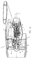
- Figures 1A and 1B illustrate a general partial fragmentary schematic view of a gas turbofan engine 10 suspended from an engine pylon 12 within an engine nacelle assembly N as is typical of an aircraft designed for subsonic operation.
- the turbofan engine 10 includes a core engine within a core nacelle C that houses a low spool 14 and high spool 24.
- the low spool 14 includes a low pressure compressor 16 and low pressure turbine 18.
- the low spool 14 drives a fan 20 connected to the low spool 14 either directly or through a gear train.
- the high spool 24 includes a high pressure compressor 26 and high pressure turbine 28.
- a combustor 30 is arranged between the high pressure compressor 26 and high pressure turbine 28.
- the low and high spools 14, 24 rotate about an engine axis of rotation A.
- the fan section 20 communicates airflow into the core nacelle C to the low pressure compressor 16 and the high pressure compressor 26. Core airflow compressed by the low pressure compressor 16 and the high pressure compressor 26 is mixed with the fuel in the combustor 30 where is ignited, and burned. The resultant high pressure combustor products are expanded through the high pressure turbine 28 and low pressure turbine 18.
- the turbines 28, 18 are rotationally coupled to the compressors 26, 16 respectively to drive the compressors 26, 16 in response to the expansion of the combustor product.
- the low pressure turbine 18 also drives the fan section 20 to communicate a bypass flow.
- a core engine exhaust exits the core nacelle C through a core nozzle 43 defined between the core nacelle C and a tail cone 33.
- the engine static structure 44 generally has sub-structures which may include a case structure often referred to as the engine backbone.
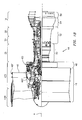
- the engine static structure 44 generally includes a fan case 46, an intermediate case (IMC) 48, a high pressure compressor case 50, a diffuser / turbine case 52, a low pressure turbine case 54, and a turbine exhaust case 56 ( Figure 1B ).
- the IMC 48 is mounted between the fan case 46 and the high pressure compressor case 50.
- the fan section 20 includes a fan rotor 32 with a plurality of circumferentially spaced radially outwardly extending fan blades 34.
- the fan blades 34 are surrounded by the fan case 46.
- the core engine case structure is secured to the fan case 46 at the IMC 48 which includes a multiple of circumferentially spaced radially extending fan exit guide vanes (FEGVs) 40 which radially span a core case section 48C and a fan case section 48F defined about the engine axis A.
- FEGVs fan exit guide vanes
- the IMC 48 may include an accessory gearbox case section 60 mounted thereto.
- the accessory gearbox case section 60 may be integral with or attachable to the IMC 48 or alternatively other engine static structure 44.
- the integrated accessory gearbox case section 60 provides significant radial area within the core nacelle C aft of the FEGVs 40 to support an engine accessory system (not shown).
- a 2.5 bleed duct structure 62 is integrated into a rear structural wall 64 of the core case section 48C to direct core airflow compressed by the low pressure compressor 16 to selectively exit out into the bypass flow stream through a bleed valve B (illustrated schematically) or other control.
- a bleed valve B illustrated schematically
- Location of the bleed valve B outside of the LPC cavity facilitates maintenance of the bleed valve B and an actuator system therefore.
- Location of the 2.5 bleed duct structure 62 just aft of the FEGVs 40 also facilitates an optimal distance between the fan blades 34 and the FEGVs 40.
- the rear structural wall 64 is located radially inward of the FEGVs 40 to at least partially provide support therefore. It should be understood that the shape and configuration of the rear structural wall 64 may be of various forms.
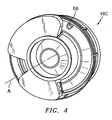
- the bleed duct structure 62 includes a multitude of discreet radially extending 2.5 bleed ducts 66 ( Figure 3 ). At least one service port 68 is located through the rear structural wall 64 generally parallel to the engine axis A ( Figure 3 ) and between the 2.5 bleed ducts 66. The service port 68 facilitates passage of a pushrod 70 as illustrated. Additional service ports 68 ( Figure 4 ) may alternatively or additionally provide pass-through service for other flows and members such as conduits.
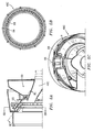
- the multitude of discreet radial extending 2.5 bleed ducts 66 extend around the engine axis A ( Figures 5B and 5C ).
- the multitude of discreet radial extending 2.5 bleed ducts 66 in one disclosed non-limiting embodiment are raked generally forward to exit just aft of the FEGVs 40 ( Figure 2 ).
Landscapes
- Engineering & Computer Science (AREA)
- Chemical & Material Sciences (AREA)
- Combustion & Propulsion (AREA)
- Mechanical Engineering (AREA)
- General Engineering & Computer Science (AREA)
- Physics & Mathematics (AREA)
- Fluid Mechanics (AREA)
- Structures Of Non-Positive Displacement Pumps (AREA)
- Turbine Rotor Nozzle Sealing (AREA)
- Control Of Turbines (AREA)
Applications Claiming Priority (1)
| Application Number | Priority Date | Filing Date | Title |
|---|---|---|---|
| US12/411,452 US8167551B2 (en) | 2009-03-26 | 2009-03-26 | Gas turbine engine with 2.5 bleed duct core case section |
Publications (3)
| Publication Number | Publication Date |
|---|---|
| EP2233703A2 true EP2233703A2 (de) | 2010-09-29 |
| EP2233703A3 EP2233703A3 (de) | 2013-05-15 |
| EP2233703B1 EP2233703B1 (de) | 2019-12-04 |
Family
ID=42034632
Family Applications (1)
| Application Number | Title | Priority Date | Filing Date |
|---|---|---|---|
| EP10250277.0A Active EP2233703B1 (de) | 2009-03-26 | 2010-02-17 | Gasturbinen-Triebwerk mit Zapfleitung im Kerngehäuse |
Country Status (2)
| Country | Link |
|---|---|
| US (1) | US8167551B2 (de) |
| EP (1) | EP2233703B1 (de) |
Cited By (1)
| Publication number | Priority date | Publication date | Assignee | Title |
|---|---|---|---|---|
| EP4506548A1 (de) | 2023-08-08 | 2025-02-12 | MTU Aero Engines AG | Luftführungssystem |
Families Citing this family (11)
| Publication number | Priority date | Publication date | Assignee | Title |
|---|---|---|---|---|
| US9784181B2 (en) | 2009-11-20 | 2017-10-10 | United Technologies Corporation | Gas turbine engine architecture with low pressure compressor hub between high and low rotor thrust bearings |
| BR102012027097B1 (pt) * | 2011-11-23 | 2022-01-04 | United Technologies Corporation | Motor de turbina a gás |
| US20130192198A1 (en) | 2012-01-31 | 2013-08-01 | Lisa I. Brilliant | Compressor flowpath |
| US9476323B2 (en) | 2012-05-31 | 2016-10-25 | United Technologies Corporation | Turbine gear assembly support having symmetrical removal features |
| US9062603B2 (en) | 2012-06-20 | 2015-06-23 | United Technologies Corporation | Four bar drive mechanism for bleed system |
| US9091209B2 (en) | 2012-06-20 | 2015-07-28 | United Technologies Corporation | Four bar bracket |
| US10167737B2 (en) | 2012-10-17 | 2019-01-01 | United Technologies Corporation | Structural guide vane circumferential load bearing shear pin |
| US10287979B2 (en) | 2012-11-12 | 2019-05-14 | United Technologies Corporation | Split intermediate case |
| US10794295B2 (en) | 2016-03-15 | 2020-10-06 | Hamilton Sunstrand Corporation | Engine bleed system with multi-tap bleed array |
| US11473497B2 (en) * | 2016-03-15 | 2022-10-18 | Hamilton Sundstrand Corporation | Engine bleed system with motorized compressor |
| US10794217B2 (en) | 2017-12-22 | 2020-10-06 | Raytheon Technologies Corporation | Bleed valve system |
Family Cites Families (25)
| Publication number | Priority date | Publication date | Assignee | Title |
|---|---|---|---|---|
| US4827713A (en) * | 1987-06-29 | 1989-05-09 | United Technologies Corporation | Stator valve assembly for a rotary machine |
| GB2259328B (en) * | 1991-09-03 | 1995-07-19 | Gen Electric | Gas turbine engine variable bleed pivotal flow splitter |
| US5261228A (en) * | 1992-06-25 | 1993-11-16 | General Electric Company | Apparatus for bleeding air |
| US5380151A (en) | 1993-10-13 | 1995-01-10 | Pratt & Whitney Canada, Inc. | Axially opening cylindrical bleed valve |
| US5477673A (en) | 1994-08-10 | 1995-12-26 | Pratt & Whitney Canada Inc. | Handling bleed valve |
| US6067791A (en) | 1997-12-11 | 2000-05-30 | Pratt & Whitney Canada Inc. | Turbine engine with a thermal valve |
| US6122905A (en) | 1998-02-13 | 2000-09-26 | Pratt & Whitney Canada Corp. | Compressor bleed valve |
| US6035627A (en) | 1998-04-21 | 2000-03-14 | Pratt & Whitney Canada Inc. | Turbine engine with cooled P3 air to impeller rear cavity |
| US6155056A (en) | 1998-06-04 | 2000-12-05 | Pratt & Whitney Canada Corp. | Cooling louver for annular gas turbine engine combustion chamber |
| FR2831608B1 (fr) * | 2001-10-31 | 2004-01-02 | Snecma Moteurs | Dispositif de decharge dans un turbo reacteur a double flux |
| US6647730B2 (en) | 2001-10-31 | 2003-11-18 | Pratt & Whitney Canada Corp. | Turbine engine having turbine cooled with diverted compressor intermediate pressure air |
| US6851255B2 (en) | 2002-12-18 | 2005-02-08 | Pratt & Whitney Canada Corp. | Normally open reverse flow flapper valve |
| US6895741B2 (en) | 2003-06-23 | 2005-05-24 | Pratt & Whitney Canada Corp. | Differential geared turbine engine with torque modulation capability |
| US7370467B2 (en) * | 2003-07-29 | 2008-05-13 | Pratt & Whitney Canada Corp. | Turbofan case and method of making |
| US7069728B2 (en) | 2003-07-29 | 2006-07-04 | Pratt & Whitney Canada Corp. | Multi-position BOV actuator |
| US7249929B2 (en) * | 2003-11-13 | 2007-07-31 | United Technologies Corporation | Bleed housing |
| US7025563B2 (en) * | 2003-12-19 | 2006-04-11 | United Technologies Corporation | Stator vane assembly for a gas turbine engine |
| US7147426B2 (en) | 2004-05-07 | 2006-12-12 | Pratt & Whitney Canada Corp. | Shockwave-induced boundary layer bleed |
| US7229247B2 (en) | 2004-08-27 | 2007-06-12 | Pratt & Whitney Canada Corp. | Duct with integrated baffle |
| US7229249B2 (en) | 2004-08-27 | 2007-06-12 | Pratt & Whitney Canada Corp. | Lightweight annular interturbine duct |
| US7287384B2 (en) | 2004-12-13 | 2007-10-30 | Pratt & Whitney Canada Corp. | Bearing chamber pressurization system |
| US7156620B2 (en) | 2004-12-21 | 2007-01-02 | Pratt & Whitney Canada Corp. | Internally cooled gas turbine airfoil and method |
| US7156619B2 (en) | 2004-12-21 | 2007-01-02 | Pratt & Whitney Canada Corp. | Internally cooled gas turbine airfoil and method |
| US7189055B2 (en) | 2005-05-31 | 2007-03-13 | Pratt & Whitney Canada Corp. | Coverplate deflectors for redirecting a fluid flow |
| US7624581B2 (en) * | 2005-12-21 | 2009-12-01 | General Electric Company | Compact booster bleed turbofan |
-
2009
- 2009-03-26 US US12/411,452 patent/US8167551B2/en active Active
-
2010
- 2010-02-17 EP EP10250277.0A patent/EP2233703B1/de active Active
Non-Patent Citations (1)
| Title |
|---|
| None |
Cited By (2)
| Publication number | Priority date | Publication date | Assignee | Title |
|---|---|---|---|---|
| EP4506548A1 (de) | 2023-08-08 | 2025-02-12 | MTU Aero Engines AG | Luftführungssystem |
| DE102023121050A1 (de) | 2023-08-08 | 2025-02-13 | MTU Aero Engines AG | Luftführungssystem |
Also Published As
| Publication number | Publication date |
|---|---|
| US8167551B2 (en) | 2012-05-01 |
| EP2233703A3 (de) | 2013-05-15 |
| EP2233703B1 (de) | 2019-12-04 |
| US20100247306A1 (en) | 2010-09-30 |
Similar Documents
| Publication | Publication Date | Title |
|---|---|---|
| EP2233703B1 (de) | Gasturbinen-Triebwerk mit Zapfleitung im Kerngehäuse | |
| US11391240B2 (en) | Gas turbine engine bifurcation located fan variable area nozzle | |
| EP2431590B1 (de) | Gasturbinenmotor mit Ablassrohr zur minimalen Verringerung des Ablassflusses und minimaler Zurückweisung von Hagel bei Hageleinnahmeereignissen | |
| US10739002B2 (en) | Fluidic nozzle assembly for a turbine engine | |
| US20260117709A1 (en) | Controlling a compressor of a turbine engine | |
| US8662417B2 (en) | Gas turbine engine fan variable area nozzle with swivable insert system | |
| EP2074317B1 (de) | Gasturbinengondelanlage mit einem Gondelstiel, der ins Gebläse eingebaut ist, mit variablem Querschnitt System | |
| US10233845B2 (en) | Bleed valve assembly for a gas turbine engine | |
| EP3165712A1 (de) | Gasturbinenmotor mit flusssteuerungsoberfläche mit einem kühlkanal | |
| US10221773B2 (en) | Bleed valve assembly for a gas turbine engine | |
| US20210040861A1 (en) | Variable guide vane sealing | |
| US8075246B2 (en) | Relief device for a turbojet and a turbojet comprising same | |
| US8650854B2 (en) | Bifurcation and aft vent used to vary fan nozzle exit area | |
| US12320299B2 (en) | Cooling air delivery system and methods thereof | |
| EP3789590B1 (de) | Synchronisierungsringdämpfer gegen pumpen | |
| EP2397654B1 (de) | Leitschaufelanordnung und Verfahren zur Montage einer Leitschaufelanordnung |
Legal Events
| Date | Code | Title | Description |
|---|---|---|---|
| PUAI | Public reference made under article 153(3) epc to a published international application that has entered the european phase |
Free format text: ORIGINAL CODE: 0009012 |
|
| AK | Designated contracting states |
Kind code of ref document: A2 Designated state(s): AT BE BG CH CY CZ DE DK EE ES FI FR GB GR HR HU IE IS IT LI LT LU LV MC MK MT NL NO PL PT RO SE SI SK SM TR |
|
| AX | Request for extension of the european patent |
Extension state: AL BA RS |
|
| PUAL | Search report despatched |
Free format text: ORIGINAL CODE: 0009013 |
|
| AK | Designated contracting states |
Kind code of ref document: A3 Designated state(s): AT BE BG CH CY CZ DE DK EE ES FI FR GB GR HR HU IE IS IT LI LT LU LV MC MK MT NL NO PL PT RO SE SI SK SM TR |
|
| AX | Request for extension of the european patent |
Extension state: AL BA RS |
|
| RIC1 | Information provided on ipc code assigned before grant |
Ipc: F02K 3/06 20060101ALI20130411BHEP Ipc: F02C 9/18 20060101AFI20130411BHEP |
|
| 17P | Request for examination filed |
Effective date: 20131115 |
|
| RBV | Designated contracting states (corrected) |
Designated state(s): AT BE BG CH CY CZ DE DK EE ES FI FR GB GR HR HU IE IS IT LI LT LU LV MC MK MT NL NO PL PT RO SE SI SK SM TR |
|
| RAP1 | Party data changed (applicant data changed or rights of an application transferred) |
Owner name: UNITED TECHNOLOGIES CORPORATION |
|
| STAA | Information on the status of an ep patent application or granted ep patent |
Free format text: STATUS: EXAMINATION IS IN PROGRESS |
|
| 17Q | First examination report despatched |
Effective date: 20170324 |
|
| GRAP | Despatch of communication of intention to grant a patent |
Free format text: ORIGINAL CODE: EPIDOSNIGR1 |
|
| STAA | Information on the status of an ep patent application or granted ep patent |
Free format text: STATUS: GRANT OF PATENT IS INTENDED |
|
| INTG | Intention to grant announced |
Effective date: 20190618 |
|
| GRAS | Grant fee paid |
Free format text: ORIGINAL CODE: EPIDOSNIGR3 |
|
| GRAA | (expected) grant |
Free format text: ORIGINAL CODE: 0009210 |
|
| STAA | Information on the status of an ep patent application or granted ep patent |
Free format text: STATUS: THE PATENT HAS BEEN GRANTED |
|
| AK | Designated contracting states |
Kind code of ref document: B1 Designated state(s): AT BE BG CH CY CZ DE DK EE ES FI FR GB GR HR HU IE IS IT LI LT LU LV MC MK MT NL NO PL PT RO SE SI SK SM TR |
|
| REG | Reference to a national code |
Ref country code: GB Ref legal event code: FG4D |
|
| REG | Reference to a national code |
Ref country code: CH Ref legal event code: EP |
|
| REG | Reference to a national code |
Ref country code: AT Ref legal event code: REF Ref document number: 1209699 Country of ref document: AT Kind code of ref document: T Effective date: 20191215 |
|
| REG | Reference to a national code |
Ref country code: DE Ref legal event code: R096 Ref document number: 602010062226 Country of ref document: DE |
|
| REG | Reference to a national code |
Ref country code: IE Ref legal event code: FG4D |
|
| REG | Reference to a national code |
Ref country code: NL Ref legal event code: MP Effective date: 20191204 |
|
| REG | Reference to a national code |
Ref country code: LT Ref legal event code: MG4D |
|
| PG25 | Lapsed in a contracting state [announced via postgrant information from national office to epo] |
Ref country code: ES Free format text: LAPSE BECAUSE OF FAILURE TO SUBMIT A TRANSLATION OF THE DESCRIPTION OR TO PAY THE FEE WITHIN THE PRESCRIBED TIME-LIMIT Effective date: 20191204 Ref country code: LT Free format text: LAPSE BECAUSE OF FAILURE TO SUBMIT A TRANSLATION OF THE DESCRIPTION OR TO PAY THE FEE WITHIN THE PRESCRIBED TIME-LIMIT Effective date: 20191204 Ref country code: NO Free format text: LAPSE BECAUSE OF FAILURE TO SUBMIT A TRANSLATION OF THE DESCRIPTION OR TO PAY THE FEE WITHIN THE PRESCRIBED TIME-LIMIT Effective date: 20200304 Ref country code: GR Free format text: LAPSE BECAUSE OF FAILURE TO SUBMIT A TRANSLATION OF THE DESCRIPTION OR TO PAY THE FEE WITHIN THE PRESCRIBED TIME-LIMIT Effective date: 20200305 Ref country code: BG Free format text: LAPSE BECAUSE OF FAILURE TO SUBMIT A TRANSLATION OF THE DESCRIPTION OR TO PAY THE FEE WITHIN THE PRESCRIBED TIME-LIMIT Effective date: 20200304 Ref country code: FI Free format text: LAPSE BECAUSE OF FAILURE TO SUBMIT A TRANSLATION OF THE DESCRIPTION OR TO PAY THE FEE WITHIN THE PRESCRIBED TIME-LIMIT Effective date: 20191204 Ref country code: SE Free format text: LAPSE BECAUSE OF FAILURE TO SUBMIT A TRANSLATION OF THE DESCRIPTION OR TO PAY THE FEE WITHIN THE PRESCRIBED TIME-LIMIT Effective date: 20191204 Ref country code: LV Free format text: LAPSE BECAUSE OF FAILURE TO SUBMIT A TRANSLATION OF THE DESCRIPTION OR TO PAY THE FEE WITHIN THE PRESCRIBED TIME-LIMIT Effective date: 20191204 |
|
| PG25 | Lapsed in a contracting state [announced via postgrant information from national office to epo] |
Ref country code: HR Free format text: LAPSE BECAUSE OF FAILURE TO SUBMIT A TRANSLATION OF THE DESCRIPTION OR TO PAY THE FEE WITHIN THE PRESCRIBED TIME-LIMIT Effective date: 20191204 |
|
| PG25 | Lapsed in a contracting state [announced via postgrant information from national office to epo] |
Ref country code: NL Free format text: LAPSE BECAUSE OF FAILURE TO SUBMIT A TRANSLATION OF THE DESCRIPTION OR TO PAY THE FEE WITHIN THE PRESCRIBED TIME-LIMIT Effective date: 20191204 Ref country code: PT Free format text: LAPSE BECAUSE OF FAILURE TO SUBMIT A TRANSLATION OF THE DESCRIPTION OR TO PAY THE FEE WITHIN THE PRESCRIBED TIME-LIMIT Effective date: 20200429 Ref country code: CZ Free format text: LAPSE BECAUSE OF FAILURE TO SUBMIT A TRANSLATION OF THE DESCRIPTION OR TO PAY THE FEE WITHIN THE PRESCRIBED TIME-LIMIT Effective date: 20191204 Ref country code: RO Free format text: LAPSE BECAUSE OF FAILURE TO SUBMIT A TRANSLATION OF THE DESCRIPTION OR TO PAY THE FEE WITHIN THE PRESCRIBED TIME-LIMIT Effective date: 20191204 Ref country code: EE Free format text: LAPSE BECAUSE OF FAILURE TO SUBMIT A TRANSLATION OF THE DESCRIPTION OR TO PAY THE FEE WITHIN THE PRESCRIBED TIME-LIMIT Effective date: 20191204 |
|
| PG25 | Lapsed in a contracting state [announced via postgrant information from national office to epo] |
Ref country code: SK Free format text: LAPSE BECAUSE OF FAILURE TO SUBMIT A TRANSLATION OF THE DESCRIPTION OR TO PAY THE FEE WITHIN THE PRESCRIBED TIME-LIMIT Effective date: 20191204 Ref country code: IS Free format text: LAPSE BECAUSE OF FAILURE TO SUBMIT A TRANSLATION OF THE DESCRIPTION OR TO PAY THE FEE WITHIN THE PRESCRIBED TIME-LIMIT Effective date: 20200404 Ref country code: SM Free format text: LAPSE BECAUSE OF FAILURE TO SUBMIT A TRANSLATION OF THE DESCRIPTION OR TO PAY THE FEE WITHIN THE PRESCRIBED TIME-LIMIT Effective date: 20191204 |
|
| REG | Reference to a national code |
Ref country code: DE Ref legal event code: R097 Ref document number: 602010062226 Country of ref document: DE |
|
| REG | Reference to a national code |
Ref country code: AT Ref legal event code: MK05 Ref document number: 1209699 Country of ref document: AT Kind code of ref document: T Effective date: 20191204 |
|
| REG | Reference to a national code |
Ref country code: CH Ref legal event code: PL |
|
| PLBE | No opposition filed within time limit |
Free format text: ORIGINAL CODE: 0009261 |
|
| STAA | Information on the status of an ep patent application or granted ep patent |
Free format text: STATUS: NO OPPOSITION FILED WITHIN TIME LIMIT |
|
| REG | Reference to a national code |
Ref country code: BE Ref legal event code: MM Effective date: 20200229 |
|
| PG25 | Lapsed in a contracting state [announced via postgrant information from national office to epo] |
Ref country code: DK Free format text: LAPSE BECAUSE OF FAILURE TO SUBMIT A TRANSLATION OF THE DESCRIPTION OR TO PAY THE FEE WITHIN THE PRESCRIBED TIME-LIMIT Effective date: 20191204 Ref country code: MC Free format text: LAPSE BECAUSE OF FAILURE TO SUBMIT A TRANSLATION OF THE DESCRIPTION OR TO PAY THE FEE WITHIN THE PRESCRIBED TIME-LIMIT Effective date: 20191204 Ref country code: LU Free format text: LAPSE BECAUSE OF NON-PAYMENT OF DUE FEES Effective date: 20200217 |
|
| 26N | No opposition filed |
Effective date: 20200907 |
|
| PG25 | Lapsed in a contracting state [announced via postgrant information from national office to epo] |
Ref country code: PL Free format text: LAPSE BECAUSE OF FAILURE TO SUBMIT A TRANSLATION OF THE DESCRIPTION OR TO PAY THE FEE WITHIN THE PRESCRIBED TIME-LIMIT Effective date: 20191204 Ref country code: SI Free format text: LAPSE BECAUSE OF FAILURE TO SUBMIT A TRANSLATION OF THE DESCRIPTION OR TO PAY THE FEE WITHIN THE PRESCRIBED TIME-LIMIT Effective date: 20191204 Ref country code: AT Free format text: LAPSE BECAUSE OF FAILURE TO SUBMIT A TRANSLATION OF THE DESCRIPTION OR TO PAY THE FEE WITHIN THE PRESCRIBED TIME-LIMIT Effective date: 20191204 Ref country code: CH Free format text: LAPSE BECAUSE OF NON-PAYMENT OF DUE FEES Effective date: 20200229 Ref country code: LI Free format text: LAPSE BECAUSE OF NON-PAYMENT OF DUE FEES Effective date: 20200229 |
|
| PG25 | Lapsed in a contracting state [announced via postgrant information from national office to epo] |
Ref country code: IE Free format text: LAPSE BECAUSE OF NON-PAYMENT OF DUE FEES Effective date: 20200217 Ref country code: IT Free format text: LAPSE BECAUSE OF FAILURE TO SUBMIT A TRANSLATION OF THE DESCRIPTION OR TO PAY THE FEE WITHIN THE PRESCRIBED TIME-LIMIT Effective date: 20191204 |
|
| PG25 | Lapsed in a contracting state [announced via postgrant information from national office to epo] |
Ref country code: BE Free format text: LAPSE BECAUSE OF NON-PAYMENT OF DUE FEES Effective date: 20200229 |
|
| PG25 | Lapsed in a contracting state [announced via postgrant information from national office to epo] |
Ref country code: TR Free format text: LAPSE BECAUSE OF FAILURE TO SUBMIT A TRANSLATION OF THE DESCRIPTION OR TO PAY THE FEE WITHIN THE PRESCRIBED TIME-LIMIT Effective date: 20191204 Ref country code: MT Free format text: LAPSE BECAUSE OF FAILURE TO SUBMIT A TRANSLATION OF THE DESCRIPTION OR TO PAY THE FEE WITHIN THE PRESCRIBED TIME-LIMIT Effective date: 20191204 Ref country code: CY Free format text: LAPSE BECAUSE OF FAILURE TO SUBMIT A TRANSLATION OF THE DESCRIPTION OR TO PAY THE FEE WITHIN THE PRESCRIBED TIME-LIMIT Effective date: 20191204 |
|
| PG25 | Lapsed in a contracting state [announced via postgrant information from national office to epo] |
Ref country code: MK Free format text: LAPSE BECAUSE OF FAILURE TO SUBMIT A TRANSLATION OF THE DESCRIPTION OR TO PAY THE FEE WITHIN THE PRESCRIBED TIME-LIMIT Effective date: 20191204 |
|
| REG | Reference to a national code |
Ref country code: DE Ref legal event code: R081 Ref document number: 602010062226 Country of ref document: DE Owner name: RAYTHEON TECHNOLOGIES CORPORATION (N.D.GES.D.S, US Free format text: FORMER OWNER: UNITED TECHNOLOGIES CORP., FARMINGTON, CONN., US Ref country code: DE Ref legal event code: R081 Ref document number: 602010062226 Country of ref document: DE Owner name: RTX CORPORATION (N.D.GES.D. STAATES DELAWARE),, US Free format text: FORMER OWNER: UNITED TECHNOLOGIES CORP., FARMINGTON, CONN., US |
|
| P01 | Opt-out of the competence of the unified patent court (upc) registered |
Effective date: 20230519 |
|
| REG | Reference to a national code |
Ref country code: DE Ref legal event code: R081 Ref document number: 602010062226 Country of ref document: DE Owner name: RTX CORPORATION (N.D.GES.D. STAATES DELAWARE),, US Free format text: FORMER OWNER: RAYTHEON TECHNOLOGIES CORPORATION (N.D.GES.D.STAATES DELAWARE), ARLINGTON, VA, US |
|
| PGFP | Annual fee paid to national office [announced via postgrant information from national office to epo] |
Ref country code: GB Payment date: 20260121 Year of fee payment: 17 |
|
| PGFP | Annual fee paid to national office [announced via postgrant information from national office to epo] |
Ref country code: DE Payment date: 20260121 Year of fee payment: 17 |
|
| PGFP | Annual fee paid to national office [announced via postgrant information from national office to epo] |
Ref country code: FR Payment date: 20260121 Year of fee payment: 17 |