EP4506295A1 - Verfahren zur erstellung eines mehrstöckigen, eine aufzuganlage umfassenden gebäudes und turmkran - Google Patents
Verfahren zur erstellung eines mehrstöckigen, eine aufzuganlage umfassenden gebäudes und turmkran Download PDFInfo
- Publication number
- EP4506295A1 EP4506295A1 EP23190436.8A EP23190436A EP4506295A1 EP 4506295 A1 EP4506295 A1 EP 4506295A1 EP 23190436 A EP23190436 A EP 23190436A EP 4506295 A1 EP4506295 A1 EP 4506295A1
- Authority
- EP
- European Patent Office
- Prior art keywords
- shaft
- elevator
- crane
- building
- tower
- Prior art date
- Legal status (The legal status is an assumption and is not a legal conclusion. Google has not performed a legal analysis and makes no representation as to the accuracy of the status listed.)
- Withdrawn
Links
Images


Classifications
-
- B—PERFORMING OPERATIONS; TRANSPORTING
- B66—HOISTING; LIFTING; HAULING
- B66C—CRANES; LOAD-ENGAGING ELEMENTS OR DEVICES FOR CRANES, CAPSTANS, WINCHES, OR TACKLES
- B66C23/00—Cranes comprising essentially a beam, boom, or triangular structure acting as a cantilever and mounted for translatory of swinging movements in vertical or horizontal planes or a combination of such movements, e.g. jib-cranes, derricks, tower cranes
- B66C23/18—Cranes comprising essentially a beam, boom, or triangular structure acting as a cantilever and mounted for translatory of swinging movements in vertical or horizontal planes or a combination of such movements, e.g. jib-cranes, derricks, tower cranes specially adapted for use in particular purposes
- B66C23/26—Cranes comprising essentially a beam, boom, or triangular structure acting as a cantilever and mounted for translatory of swinging movements in vertical or horizontal planes or a combination of such movements, e.g. jib-cranes, derricks, tower cranes specially adapted for use in particular purposes for use on building sites; constructed, e.g. with separable parts, to facilitate rapid assembly or dismantling, for operation at successively higher levels, for transport by road or rail
-
- B—PERFORMING OPERATIONS; TRANSPORTING
- B66—HOISTING; LIFTING; HAULING
- B66C—CRANES; LOAD-ENGAGING ELEMENTS OR DEVICES FOR CRANES, CAPSTANS, WINCHES, OR TACKLES
- B66C23/00—Cranes comprising essentially a beam, boom, or triangular structure acting as a cantilever and mounted for translatory of swinging movements in vertical or horizontal planes or a combination of such movements, e.g. jib-cranes, derricks, tower cranes
- B66C23/18—Cranes comprising essentially a beam, boom, or triangular structure acting as a cantilever and mounted for translatory of swinging movements in vertical or horizontal planes or a combination of such movements, e.g. jib-cranes, derricks, tower cranes specially adapted for use in particular purposes
- B66C23/26—Cranes comprising essentially a beam, boom, or triangular structure acting as a cantilever and mounted for translatory of swinging movements in vertical or horizontal planes or a combination of such movements, e.g. jib-cranes, derricks, tower cranes specially adapted for use in particular purposes for use on building sites; constructed, e.g. with separable parts, to facilitate rapid assembly or dismantling, for operation at successively higher levels, for transport by road or rail
- B66C23/28—Cranes comprising essentially a beam, boom, or triangular structure acting as a cantilever and mounted for translatory of swinging movements in vertical or horizontal planes or a combination of such movements, e.g. jib-cranes, derricks, tower cranes specially adapted for use in particular purposes for use on building sites; constructed, e.g. with separable parts, to facilitate rapid assembly or dismantling, for operation at successively higher levels, for transport by road or rail constructed to operate at successively higher levels
- B66C23/283—Cranes comprising essentially a beam, boom, or triangular structure acting as a cantilever and mounted for translatory of swinging movements in vertical or horizontal planes or a combination of such movements, e.g. jib-cranes, derricks, tower cranes specially adapted for use in particular purposes for use on building sites; constructed, e.g. with separable parts, to facilitate rapid assembly or dismantling, for operation at successively higher levels, for transport by road or rail constructed to operate at successively higher levels with frameworks composed of assembled elements
-
- B—PERFORMING OPERATIONS; TRANSPORTING
- B66—HOISTING; LIFTING; HAULING
- B66B—ELEVATORS; ESCALATORS OR MOVING WALKWAYS
- B66B19/00—Mining-hoist operation
-
- E—FIXED CONSTRUCTIONS
- E04—BUILDING
- E04B—GENERAL BUILDING CONSTRUCTIONS; WALLS, e.g. PARTITIONS; ROOFS; FLOORS; CEILINGS; INSULATION OR OTHER PROTECTION OF BUILDINGS
- E04B1/00—Constructions in general; Structures which are not restricted either to walls, e.g. partitions, or floors or ceilings or roofs
- E04B1/35—Extraordinary methods of construction, e.g. lift-slab, jack-block
- E04B2001/3588—Extraordinary methods of construction, e.g. lift-slab, jack-block using special lifting or handling devices, e.g. gantries, overhead conveying rails
Definitions
- the invention relates to a method for constructing a multi-storey building comprising an elevator system according to the preamble of claim 1 and a tower crane according to the preamble of claim 7.
- a crane When constructing a building, particularly a multi-storey building with an elevator system, a crane is required to move building materials.
- the crane is usually required for a longer period of time, so that it remains at the building site for the period mentioned.
- the building site can also be referred to as the construction site of the building and the elevator system.
- Tower cranes are usually used as cranes, which have a vertically extending crane tower and a horizontally extending crane boom arranged at the top of the crane tower.
- the crane boom usually has a so-called trolley, which can be moved along the crane boom and carries a hoist rope.
- a hook is usually attached to the hoist rope, by means of which a load, for example in the form of building materials, can be attached and thus moved with the crane boom and thus with the tower crane.
- Such a tower crane is used, for example, in the DE 4206359 A1 described.
- the crane tower In the case of well-known tower cranes, the crane tower consists of a lattice girder construction or a metal truss and either stands on a so-called undercarriage or is firmly anchored in the ground. The crane tower therefore requires a space on the construction site or at the place where the building is being constructed.
- the object of the invention is in particular to propose a method and a tower crane which require little space at the construction site of the building. According to the invention, this object is achieved with a method having the features of claim 1 and a tower crane having the features of claim 7.
- the inventive method for constructing a multi-storey comprises the method steps of providing shaft modules and stacking the provided shaft modules on a floor slab of the building to form an elevator shaft of the elevator system.
- it comprises the further method steps of arranging a crane boom at the top of the elevator shaft and moving building materials for the construction of the building using the crane boom.
- the elevator shaft of the elevator system thus forms the crane tower that supports the crane boom.
- the tower crane formed from the elevator shaft and crane boom thus uses the footprint of the elevator shaft that is already there and therefore does not require any additional space at the construction site of the building.
- the crane tower required in addition to the elevator shaft would require a footprint and therefore space which is now eliminated, thereby achieving numerous advantages.
- the space required at the construction site is therefore particularly small.
- the elevator shaft which is required anyway, as a crane tower, no additional crane tower needs to be built, which saves time, money and transport costs for the additional crane tower.
- the use of the method according to the invention therefore also enables a particularly cost-effective and less time-consuming construction of a building.
- the above-mentioned task is also solved by a tower crane with a crane tower and a crane boom arranged at the top of the crane tower.
- the crane tower is designed as an elevator shaft of an elevator system consisting of stacked shaft modules.
- the tower crane according to the invention also offers the advantages described for the method.
- the WO 2022/233803 A1 a method for creating an elevator shaft from individual shaft modules that are stacked on top of each other to form an elevator shaft.
- This also describes, at least implicitly, a method for creating a multi-story building that includes an elevator system.
- directional information such as up, down and sideways or vertical and horizontal refers to the orientation of the respective component in an operating state of the elevator system.
- the operating state of the elevator system is understood to be the state after installation has been completed and the elevator system has been put into operation.
- people and/or goods can be transported in the elevator system cabin between floors of the building in which the elevator system is located.
- the building constructed using the method according to the invention is multi-storey, i.e. it has several floors, for example three to ten.
- the provision of a shaft module is understood here to mean that the shaft module is manufactured at the production site and transported to the production site.
- the various shaft modules can be manufactured at different production sites and different manufacturing steps can be carried out at different production sites for each shaft module.
- At least some of the shaft modules not necessarily all shaft modules, have shaft doors.
- a lowest shaft module and a topmost shaft module of the elevator shaft may not have a shaft door.
- a shaft module may have one or more than one shaft door.
- a shaft door closes off an opening in a shaft module, a so-called shaft opening. If no cabin is arranged at a shaft door, the shaft door is closed and thus prevents access from the floor into the elevator shaft.
- a shaft door is usually opened and closed together with a cabin door of the cabin. If there is at least one shaft door on a floor, a cabin of the elevator system can stop at this shaft door and access to the cabin can be made possible by opening the shaft door.
- the lowest shaft module is placed on the floor slab first.
- This lowest shaft module can also be referred to as a pit module.
- Arranging the pit module on the floor slab here means that the pit module is set down or placed on the floor slab. This is done in particular by means of a mobile crane, for example in the form of a so-called telescopic mobile crane.
- a mobile crane is understood here to mean a mobile crane, in particular a mobile jib crane on a wheeled or tracked vehicle.
- the entire pit module can be aligned, in particular by placing leveling plates underneath, for example to compensate for unevenness in the floor plate or to ensure that the side walls are vertically aligned.
- One or more lasers can be used to align the pit module and other shaft modules.
- the floor plate does not have to be completely flat; in particular, it can have a recess into which the pit module is inserted. It is also possible that when the elevator shaft is being created, not the entire base plate yet exists, but only a part of the base plate on which the pit module is placed.
- At least one, usually more than one, further pit module is placed on the pit module using the mobile crane.
- the other identically designed shaft modules are referred to here as basic modules.
- the elevator shaft is closed at the top in particular by a so-called top module, which has a shaft ceiling and optionally a drive for the elevator system. It is also possible for the elevator shaft to have a basic module as the top shaft module and for the elevator shaft to be closed at the top at a later point in time with a top module or a shaft ceiling.
- a crane boom is arranged at the top of the elevator shaft. This results in the elevator shaft as a crane tower and the crane boom as a tower crane.
- the crane boom is designed primarily as a lattice structure or a truss made of metal. It can basically be designed like the known crane booms of tower cranes.
- the crane boom extends horizontally in particular and has a trolley which can be moved along the crane boom and carries a hoist rope with a hook.
- the crane boom has a so-called slewing mechanism, by means of which the crane boom can be rotated about a vertical axis of rotation running through the elevator shaft.
- the tower crane formed by the elevator shaft as a crane tower and the crane boom is therefore designed in particular as a top-slewing tower crane.
- the crane boom is arranged on the elevator shaft in particular via an outer side of the top shaft module of the elevator shaft.
- An outer side is understood to mean the side of a wall or the ceiling of a shaft module facing outwards.
- two double-T beams made of metal can be fixed, for example screwed, on top and thus on the outside of the shaft ceiling of the top module.
- the crane boom, in particular the slewing gear of the crane boom is then fixed on these double-T beams, for example screwed or clamped with suitable clamps.
- a frame in particular a metal frame, is first fixed, in particular screwed, on the outside of the top shaft module of the elevator shaft.
- An outer contour of the frame can be matched to an inner contour of a recess in the crane boom, so that the The crane boom can be placed or pushed onto the frame from above and then connected to the frame, in particular screwed.
- the crane boom and the frame have corresponding recesses provided for this purpose, for example in the form of through holes.
- the double-T beams and the frame mentioned are arranged on the top module in particular before the top module is placed on the elevator shaft. This can be done, for example, at the manufacturing site or before it is placed at the construction site. It is also possible for the crane boom to be attached, in particular screwed, directly to the outside of the top shaft module and thus without the use of beams or a frame.
- the elevator shaft is still open at the top, i.e. it is not yet closed at the top by a pit module with a shaft ceiling.
- the crane boom can also be arranged on the elevator shaft via an inner side of the top shaft module of the elevator shaft.
- the resulting tower crane can be put into operation. This may require further steps, such as arranging a counterweight on the crane boom. These steps basically correspond to the steps that are also necessary for commissioning of known tower cranes.
- the building materials required for the construction of the building for example in the form of concrete parts, concrete, bricks or tiles, can be moved to the desired location using the tower crane.
- the elevator system is used as a construction elevator during the construction of the building.
- the elevator is therefore used as a construction elevator before the crane boom is removed from the elevator shaft.
- a construction elevator is understood to be an elevator with which building materials and construction workers can be transported during the construction of a building.
- Known construction elevators are often designed as temporary elevators on the outside facade of a building under construction. Such external elevators are comparatively expensive, complex to install, slow and loud. Using the building's elevator system as a construction elevator makes such an external elevator superfluous, which enables the building to be constructed cost-effectively and prevents unwanted noise emissions during construction.
- a cabin of the elevator system only drives to shaft doors of floors of the building that have already been created; the elevator therefore only serves floors that have already been created.
- an elevator control system of the elevator system is configured accordingly via a configuration interface.
- side walls of a shaft module adjacent to another shaft module have an outer horizontal edge which is arranged below an inner horizontal edge of the side walls mentioned. This can effectively prevent water from penetrating the elevator shaft from the outside.
- all horizontal edges of the shaft modules are designed in this way.
- the side walls of the shaft modules have a stepped cross-section for this purpose, for example.
- the elevator shaft and thus at least some shaft modules have shaft doors.
- These shaft doors are covered on the outside by means of a cover before the shaft modules are placed on top of one another, or are provided with such a cover.
- the cover is arranged on the shaft modules in particular at the place of manufacture. The cover is removed when or before the shaft door is approached by the elevator car. This protects shaft doors that do not yet have a floor built from the effects of the weather and can prevent water from entering the elevator shaft via these shaft doors.
- the cover mentioned can be designed, for example, as a tarpaulin or a plate, for example made of wood or plastic.
- adjacent shaft modules are connected to each other in a tensile manner. This ensures that the elevator shaft created is particularly stable and sturdy.
- a tensile connection is understood here to mean that adjacent shaft modules are not separated from each other in the vertical direction. can be.
- connection mentioned is made, for example, by means of tabs connecting two adjacent shaft modules, in particular galvanized steel tabs.
- the tabs can be arranged on the outside and/or inside of the shaft modules.
- a second basic module 16 is placed from above on a not yet completed elevator shaft 11 by means of a mobile crane 20.
- the mobile crane 20 has a telescopic boom 7, which is arranged on a wheeled vehicle 9.
- a pit module 14 was first placed on a base plate 13 of a building to be constructed (19 in Fig. 3 ) using the mobile crane 20.
- the base plate 13 has a recess 17 into which the pit module 14 is inserted and which thus accommodates a lower part of the pit module 14.
- a first base module 16 was then placed and aligned on the pit module 14 using the mobile crane 20.
- the first base module 16 is then connected to the pit module 14 in a tension-resistant manner using tabs 15, in particular metal tabs.
- tabs 15, in particular metal tabs are arranged on two opposite side walls 25 of the pit module 14 and the first base module 16. It is also possible for corresponding tabs to be arranged on all side walls.
- All other attached shaft modules are also connected to each other in a tension-resistant manner in this way.
- the pit module 14 and the basic modules 16 each have a shaft door 21, which is covered by a cover 23 in the form of a plate when the unfinished elevator shaft 11 is created.
- a cabin (22 in Fig. 3 ) of the elevator system can stop at a shaft door 21.
- Fig. 2 is an enlarged view of two adjacent side walls 25 of the pit module 14 and the first base module 16. These are the Fig. 1 right side walls 25.
- the side walls 25 have a stepped cross-section such that an outer horizontal edge 27, i.e. the horizontal edge on an outside, is arranged below an inner horizontal edge 29, i.e. the horizontal edge on an inside. This applies in particular to all horizontal edges of all shaft modules.
- a pit module (18 in Fig. 3 ) using the mobile crane 20 and is connected to the shaft module underneath in a tension-resistant manner.
- the resulting completed elevator shaft 12 is in Fig. 3 as part of an elevator system 10.
- the shaft modules 14, 16, 18 mentioned were pre-produced in a factory and thus at a production site and provided with elevator components. They were then brought from the production site to the construction site of the building 19 housing the elevator system 10 and thus to a production site.
- elevator components required for operation of the elevator system 10 are installed and aligned. This can be referred to as installation of the elevator system 10.
- the installation is therefore carried out before the building is completed and therefore before the floors of the building are constructed.
- the elevator system can also be installed after the building is completed.
- the resulting elevator system 10 of the Fig. 3 has a cabin 22 which is arranged along Fig. 3 not shown guide rails in the elevator shaft 12.
- the elevator system 10 has a support means 24, the first end 26 of which is fixed in the top module 18. It then runs around the bottom of the cabin 22 and is guided over a drive machine 28 arranged opposite the first end 26 of the support means 24 in the top module 18. From there it runs through a suspension of a counterweight 30 to its second end 32, which is fixed in the area of the drive machine 28.
- the drive machine 28 can move the support means 24 and thus the cabin 22 in the elevator shaft 12.
- the cabin 22 is connected via a hanging cable 34 to an elevator control 36 arranged in the top module 18.
- the hanging cable 34 enables a power supply and communication with the cabin 22.
- the elevator control 36 has a configuration interface via which it can be configured.
- the configuration interface is designed as a known interface to a mobile configuration device (not shown), in the form of a smartphone with a corresponding app.
- the elevator system 10 After the installation of the elevator system 10, the elevator system 10 is put into operation, which also takes place before the building is completed and therefore before all floors of the building have been constructed.
- the positions of the various shaft doors 21 are stored in the elevator control 36. This is done using a known, automated learning run. In addition, safety checks are carried out during commissioning.
- the elevator system 10 After the elevator system 10 has been put into operation, it can be used as a construction elevator.
- the cabin 22 can be used to transport construction workers and construction materials during the construction of the building 19. Only shaft doors 21 that are on a floor that has already been constructed are approached.
- the elevator system can also only be put into operation after the building has been completed. In this case, the elevator system would not be used as a construction elevator.
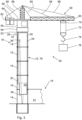
- the crane boom 50 shown is arranged on the top shaft module and thus on the top module 18 of the elevator shaft 12.
- Two parallel double-T beams 52 are fixed to an outside of a ceiling of the top module 18 and thus on the shaft ceiling using screws not shown.
- the double-T beams 52 were already fixed to the top module 18 at the manufacturing site.
- the crane boom 50 has a slewing gear 54 which is mounted on the rests on double-T beams 52 and is screwed to the double-T beams 52 with screws not shown. By means of the slewing gear 54, the crane boom 50 can be rotated about a vertical axis of rotation running through the elevator shaft 12.
- the slewing gear 54 is connected to a driver's cab 56 at the top, in which a crane operator can stay.
- a horizontal crossbeam 58 runs on top of the driver's cab 56, which connects a horizontally extending boom 60 designed as a lattice girder with a counter-jib 62. Two cuboid counterweights 64 are held in the counter-jib 62.
- the crossbeam 58 is connected to a crane tower 66, also designed as a lattice girder, to which the counter-jib 62 and the boom 60 are guyed with a total of four traction cables 68.
- a trolley 70 is arranged on the boom 60 so that it can be moved horizontally along the boom 60.
- a vertically movable hoist rope 72 with a hook 74 is arranged on the trolley 70.
- the hook 74 can thus be moved both horizontally and vertically and rotated about the above-mentioned axis of rotation, whereby building material for the construction of the house 19, for example in the form of a box 76 with tiles, can be moved.
- the building material is thus moved by means of the crane boom 50.
- a lowest floor 41 has been created in the building 19 which houses the elevator system 10.
- the elevator shaft 12 thus forms a crane tower 78, which together with the crane boom 50 forms a tower crane 80.
- the procedure for constructing a multi-storey building with an elevator system thus includes Fig. 4 following procedural steps.
- step S 1 a pit module, one or more base modules and a top module are manufactured in a factory at a production site and equipped with elevator components.
- step S2 the shaft modules are transported in step S2 to the construction site of the building that will house the elevator system, i.e. to the construction site. This is done, for example, by means of a truck across the street.
- Steps S1 and S2 can together be referred to as a provision of the shaft modules.
- step S3 the pit module is first placed on a previously created floor slab of the building and then the other shaft modules are stacked on top of each other to form an elevator shaft.
- the elevator system is installed and put into operation.
- the elevator system can also be installed and put into operation after the building has been constructed or after the crane boom has been removed from the elevator shaft.
- step S5 a crane boom is arranged at the top of the elevator shaft as described above.
- step S6 the building that will house the elevator system is constructed and building materials for the construction of the building are moved using the crane boom.
- the elevator system is optionally used as a construction elevator during the construction of the building.
- the crane boom is removed from the elevator shaft using a mobile crane in step S7.
Landscapes
- Engineering & Computer Science (AREA)
- Structural Engineering (AREA)
- Transportation (AREA)
- Mechanical Engineering (AREA)
- Lift-Guide Devices, And Elevator Ropes And Cables (AREA)
Abstract
Die Erfindung betrifft ein Verfahren zur Erstellung eines mehrstöckigen, eine Aufzuganlage (10) umfassenden Gebäudes (19) mit den Verfahrensschritten Bereitstellen von Schachtmodulen (14, 16, 18) und Aufeinandersetzen der bereitgestellten Schachtmodule (14, 16, 18) auf einer Bodenplatte (13) des Gebäudes (19) zu einem Aufzugschacht (12) der Aufzuganlage (10). Erfindungsgemäss werden die weiteren Verfahrensschritte Anordnen eines Kranauslegers (50) oben am Aufzugschacht (12) und Verlagern von Baumaterial (76) für die Erstellung des Gebäudes (19) mittels des Kranauslegers (50) ausgeführt. Die Erfindung betrifft auch einen Turmkran (80) mit einem Kranturm (78) und einem oben am Kranturm (78) angeordneten Kranausleger (50), welcher als ein aus aufeinandergesetzten Schachtmodulen (14, 16, 18) bestehender Aufzugschacht (12) einer Aufzuganlage (10) ausgeführt ist.
Description
- Die Erfindung betrifft ein Verfahren zur Erstellung eines mehrstöckigen, eine Aufzuganlage umfassenden Gebäudes gemäss dem Oberbegriff des Anspruchs 1 und einen Turmkran gemäss dem Oberbegriff des Anspruchs 7.
- Bei der Erstellung eines Gebäudes, insbesondere eines mehrstöckigen, eine Aufzuganlage umfassenden Gebäudes ist für die Verlagerung von Baumaterial ein Kran notwendig. Der Kran wird meist über eine längere Zeitspanne benötigt, so dass er über die genannte Zeitspanne an der Baustelle des Gebäudes verbleibt. Die Baustelle des Gebäudes kann auch als ein Erstellungsort des Gebäudes und der Aufzuganlage bezeichnet werden. Üblicherweise werden als Kräne so genannte Turmkräne verwendet, welche einen sich vertikal erstreckenden Kranturm und einen oben am Kranturm angeordneten, sich horizontal erstreckenden Kranausleger aufweisen. Der Kranausleger verfügt meist über eine so genannte Laufkatze, welche entlang des Kranauslegers verlagert werden kann und ein Hubseil mit sich führt. Am Hubseil ist üblicherweise ein Haken angebracht, mittels welchem eine Last, beispielsweise in Form von Baumaterial angehängt und damit mit dem Kranausleger und somit mit dem Turmkran verlagert werden kann. Ein derartiger Turmkran wird beispielsweise in der
DE 4206359 A1 beschrieben. - Bei bekannten Turmkränen besteht der Kranturm aus einer Gitterträgerkonstruktion bzw. einem Fachwerkträger aus Metall und steht entweder auf einem so genannten Unterwagen oder ist fest im Boden verankert. Der Kranturm benötigt damit eine Stellfläche auf der Baustelle bzw. am Erstellungsort des Gebäudes.
- Demgegenüber ist es insbesondere die Aufgabe der Erfindung, ein Verfahren und einen Turmkran vorzuschlagen, welche wenig Platz am Erstellungsort des Gebäudes beanspruchen. Erfindungsgemäss wird diese Aufgabe mit einem Verfahren mit den Merkmalen des Anspruchs 1 und einem Turmkran mit den Merkmalen des Anspruchs 7 gelöst.
- Das erfindungsgemässe Verfahren zur Erstellung eines mehrstöckigen, eine Aufzuganlage umfassenden Gebäudes umfasst die Verfahrensschritte Bereitstellen von Schachtmodulen und Aufeinandersetzen der bereitgestellten Schachtmodule auf einer Bodenplatte des Gebäudes zu einem Aufzugschacht der Aufzuganlage. Erfindungsgemäss umfasst es die weiteren Verfahrensschritte Anordnen eines Kranauslegers oben am Aufzugschacht und Verlagern von Baumaterial für die Erstellung des Gebäudes mittels des Kranauslegers. Der Aufzugschacht der Aufzuganlage bildet damit den den Kranausleger tragenden Kranturm aus. Der aus Aufzugschacht und Kranausleger gebildete Turmkran nutzt damit die Stellfläche des sowieso vorhandenen Aufzugschachts und benötigt damit keinen zusätzlichen Platz am Erstellungsort des Gebäudes. Bei der Verwendung eines Turmkrans würde der zusätzlich zum Aufzugschacht benötigte Kranturm eine Stellfläche und damit Platz benötigen welcher nun wegfällt, wodurch zahlreiche Vorteile erzielt werden. Bei Verwendung des erfindungsgemässen Verfahrens bei der Erstellung eines Gebäudes ist der Platzbedarf am Erstellungsort damit besonders gering. Ausserdem muss durch die Nutzung des sowieso notwendigen Aufzugschachts als Kranturm kein zusätzlicher Kranturm aufgebaut werden, was Zeit, Kosten und Transportaufwand für den zusätzlichen Kranturm spart. Die Verwendung des erfindungsgemässen Verfahrens ermöglicht damit auch eine besonders kostengünstige und wenig zeitaufwändige Erstellung eines Gebäudes.
- Die genannte Aufgabe wird auch von einem Turmkran mit einem Kranturm und einem oben am Kranturm angeordneten Kranausleger gelöst. Erfindungsgemäss ist der Kranturm als ein aus aufeinandergesetzten Schachtmodulen bestehender Aufzugschacht einer Aufzuganlage ausgeführt. Der erfindungsgemässe Turmkran bietet ebenfalls die zum Verfahren beschriebenen Vorteile.
- Die im Folgenden beschriebenen Ausführungsformen und Ausführungsbeispiele der Erfindung betreffen gleichermassen das Verfahren und den Turmkran. Mit anderen Worten lassen sich im Folgenden beispielsweise unter Bezugnahme auf den Turmkran genannte Merkmale auch als Verfahrensschritte implementieren, und umgekehrt. Der Turmkran ist damit insbesondere so konfiguriert, dass mit ihm die beschriebenen Verfahren ausgeführt werden können.
- Es wurde bereits vorgeschlagen, den Aufzugschacht einer Aufzuganlage aus mehreren vorgefertigten Schachtmodulen mit Schachtwänden zu erstellen, in denen Aufzugkomponenten, wie beispielsweise Führungsschienenstücke, zumindest teilweise bereits vormontiert sind. Die Vorfertigung und die Vormontage erfolgen dabei nicht auf der Baustelle des den Aufzug umfassenden Gebäudes, also am Erstellungsort des Gebäudes und der Aufzuganlage, sondern in einer Fabrik und damit an einem Fabrikationsort. Es ist heute immer noch üblich, den Aufzugschacht zusammen mit Stockwerken des die Aufzuganlage aufnehmenden Gebäudes zu erstellen und nach Fertigstellung des Aufzugschacht die Aufzuganlage mit ihren Aufzugbauteilen wie Kabine, Gegengewicht, Antriebsmaschine und Führungsschienen im Aufzugschacht zu installieren. Demgegenüber hat beschriebene Verwendung von Schachtmodulen den Vorteil, dass für die Erstellung des Aufzugschachts und die Installation der Aufzuganlage weniger Zeit am Erstellungsort benötigt wird. Ausserdem hat die Verwendung von Schachtmodulen positive Auswirkungen auf die Qualität der Installation und die Arbeitssicherheit des Installationspersonals.
- Beispielsweise beschreibt die
WO 2022/233803 A1 ein Verfahren zur Erstellung eines Aufzugschachts aus einzelnen Schachtmodulen, die zu einem Aufzugschacht aufeinandergestapelt werden. Damit wird auch zumindest implizit ein Verfahren zur Erstellung eines mehrstöckigen, eine Aufzuganlage umfassenden Gebäudes beschrieben. - Im Folgenden beziehen sich Richtungsangaben, wie beispielsweise oben, unten und seitlich oder vertikal und horizontal auf die Ausrichtung der jeweiligen Komponente in einem Betriebszustand der Aufzuganlage. Unter dem Betriebszustand der Aufzuganlage wird dabei der Zustand nach Abschluss der Installation und einer Inbetriebnahme der Aufzuganlage verstanden. Im Betriebszustand der Aufzuganlage können damit Personen und/oder Güter in der Kabine der Aufzuganlage zwischen Stockwerken des die Aufzuganlage aufnehmenden Gebäudes transportiert werden.
- Das mit dem erfindungsgemässen Verfahren erstellte Gebäude ist mehrstöckig ausgeführt, es weist also mehrere, beispielsweise drei bis zehn Stockwerke auf. Unter einer Bereitstellung eines Schachtmoduls soll hier verstanden werden, dass das Schachtmodul am Fabrikationsort hergestellt und an den Erstellungsort transportiert wird. Die verschiedenen Schachtmodule können dabei an verschiedenen Fabrikationsorten hergestellt werden und bei jedem Schachtmodul können unterschiedliche Herstellungsschritte an unterschiedlichen Fabrikationsorten erfolgen.
- Zumindest einige der Schachtmodule, nicht zwingend alle Schachtmodule, weisen Schachttüren auf. Insbesondere können ein unterstes Schachtmodul und ein oberstes Schachtmodul des Aufzugschachts keine Schachttür aufweisen. Ein Schachtmodul kann eine oder mehr als eine Schachttür aufweisen. Eine Schachttür schliesst eine Öffnung in einem Schachtmodul, eine so genannte Schachtöffnung ab. Sofern keine Kabine an einer Schachttür angeordnet ist, ist die Schachttür geschlossen und verhindert damit einen Zugang vom Stockwerk in den Aufzugschacht. Eine Schachttür wird üblicherweise zusammen mit einer Kabinentür der Kabine geöffnet und geschlossen. Wenn sich auf einem Stockwerk zumindest eine Schachttür befindet, kann eine Kabine der Aufzuganlage an dieser Schachttür anhalten und durch Öffnen der Schachttür kann ein Zugang zur Kabine ermöglicht werden.
- Beim Aufeinandersetzen der bereitgestellten Schachtmodule auf der Bodenplatte des Gebäudes wird zuerst das unterste Schachtmodul auf der Bodenplatte angeordnet. Dieses unterste Schachtmodul kann auch als Pit-Modul bezeichnet werden. Unter dem Anordnen des Pit-Moduls auf der Bodenplatte soll hier verstanden werden, dass das Pit-Modul auf der Bodenplatte abgesetzt bzw. abgestellt wird. Dies erfolgt insbesondere mittels eines Mobilkrans, beispielsweise in Form eines so genannten Teleskop-Mobilkrans. Unter einem Mobilkran wird hier ein mobiler Kran insbesondere ein fahrbarer Auslegerkran auf einem Rad- oder Kettenfahrzeug verstanden.
- Das gesamte Pit-Modul kann nach dem Anordnen auf dem Schachtboden insbesondere durch Unterlegen von Ausgleichsplatten ausgerichtet werden, beispielsweise um Unebenheiten der Bodenplatte auszugleichen oder eine vertikale Ausrichtung der Seitenwände zu gewährleisten. Zur Ausrichtung des Pit-Moduls und auch weiterer Schachtmodule kann ein oder mehrere Laser verwendet werden. Die Bodenplatte muss nicht vollkommen eben ausgeführt sein; sie kann insbesondere eine Vertiefung aufweisen, in die das Pit-Modul eingesetzt wird. Es ist auch möglich, dass während des Erstellens des Aufzugschachts noch nicht die gesamte Grundplatte, sondern nur ein Teil der Grundplatte existiert, auf dem das Pit-Modul aufgesetzt wird.
- Auf das Pit-Modul wird insbesondere ebenfalls mit dem Mobilkran mindestens ein, üblicherweise mehr als ein weiteres Schachtmodul aufgesetzt. Diese insbesondere identisch ausgeführten weiteren Schachtmodule werden hier als Grund-Module bezeichnet. Der Aufzugschacht wird nach oben insbesondere durch ein so genanntes Top-Modul abgeschlossen, welches eine Schachtdecke und optional einen Antrieb für die Aufzuganlage aufweist. Es ist auch möglich, dass der Aufzugschacht ein Grund-Modul als oberstes Schachtmodul aufweist und der Aufzugschacht zu einem späteren Zeitpunkt mit einem Top-Modul oder einer Schachtdecke nach oben abgeschlossen wird. Nach dem Aufeinandersetzen der Schachtmodule zum Aufzugschacht der Aufzuganlage wird ein Kranausleger oben am Aufzugschacht angeordnet. Damit ergibt sich aus dem Aufzugschacht als Kranturm und dem Kranausleger ein Turmkran.
- Der Kranausleger ist insbesondere hauptsächlich als eine Gitterkonstruktion bzw. ein Fachwerkträger aus Metall ausgeführt. Er kann grundsätzlich wie bekannte Kranausleger von Turmkränen ausgeführt sein. Der Kranausleger erstreckt sich insbesondere horizontal und verfügt insbesondere über eine Laufkatze, welche entlang des Kranauslegers verlagert werden kann und ein Hubseil mit einem Haken mit sich führt.
- Der Kranausleger verfügt insbesondere über ein so genanntes Drehwerk, mittels welchem der Kranausleger um eine senkrechte, durch den Aufzugschacht verlaufende Drehachse gedreht werden kann. Der durch den Aufzugschacht als Kranturm und dem Kranausleger gebildete Turmkran ist damit insbesondere als ein obendrehender Turmdrehkran ausgeführt.
- Der Kranausleger wird insbesondere über eine Aussenseite des obersten Schachtmoduls des Aufzugschachts am Aufzugschacht angeordnet. Unter einer Aussenseite wird dabei die nach aussen gerichtete Seite einer Wand oder der Decke eines Schachtmoduls verstanden. Zum Anordnen bzw. Befestigen des Kranauslegers am Aufzugschacht können beispielsweise zwei Doppel-T-Träger aus Metall oben und damit aussen auf der Schachtdecke des Top-Modul fixiert, beispielsweise angeschraubt werden. Auf diesen Doppel-T-Trägern wird dann der Kranausleger, insbesondere das Drehwerk des Kranauslegers fixiert, beispielsweise angeschraubt oder mit passenden Klemmen angeklemmt. Es ist auch möglich, dass zuerst ein Rahmen, insbesondere ein Metallrahmen aussen am obersten Schachtmodul des Aufzugschachts befestigt, insbesondere angeschraubt wird. Eine Aussenkontur des Rahmens kann dabei auf eine Innenkontur einer Ausnehmung des Kranauslegers abgestimmt sein, so dass der Kranausleger von oben auf den Rahmen aufgesetzt bzw. aufgeschoben und anschliessend mit dem Rahmen verbunden, insbesondere verschraubt werden kann. Der Kranausleger und der Rahmen weisen dazu insbesondere dazu vorgesehene korrespondierende Ausnehmungen, beispielsweise in Form von Durchgangslöchern auf. Die genannten Doppel-T-Träger und der genannte Rahmen werden insbesondere vor dem Aufsetzen des Top-Moduls auf dem Aufzugschachts am Top-Modul angeordnet. Dies kann beispielsweise am Fabrikationsort oder vor dem Aufsetzen am Erstellungsort erfolgen. Es ist auch möglich, dass der Kranausleger direkt und damit ohne Zwischenschaltung von Trägern oder eines Rahmens an der Aussenseite des obersten Schachtmoduls befestigt, insbesondere verschraubt wird.
- Es ist auch möglich, dass beim Anordnen des Kranauslegers am obersten Schachtmodul der Aufzugschacht nach oben noch offen ist, er also noch nicht nach oben durch ein Pit-Modul mit einer Schachtdecke abgeschlossen ist. In diesem Fall kann der Kranausleger auch über eine Innenseite des obersten Schachtmoduls des Aufzugschachts am Aufzugschacht angeordnet sein.
- Nach dem Anordnen des Kranauslegers am Aufzugschacht der Aufzuganlage kann der damit entstandene Turmkran in Betrieb genommen werden. Dazu können weitere Schritte, wie beispielsweise Anordnen eines Gegengewichts am Kranausleger, notwendig sein. Diese Schritte entsprechen grundsätzlich Schritten, die auch bei bekannten Turmkränen für die Inbetriebnahme notwendig sind.
- Sobald der so entstandene Turmkran betriebsbereit ist, kann für die Erstellung des Gebäudes notwendiges Baumaterial, beispielsweise in Form von Betonteilen, Beton, Ziegelsteinen oder Fliesen mit dem Turmkran an den gewünschten Ort verlagert werden.
- In Ausgestaltung der Erfindung wird die Aufzuganlage während der Erstellung des Gebäudes als Bauaufzug genutzt. Der Aufzug wird damit also vor einem Entfernen des Kranauslegers vom Aufzugschacht als Bauaufzug genutzt. Unter einem Bauaufzug wird dabei ein Aufzug verstanden, mit welchem beim Bau eines Gebäudes Baumaterial und Bauarbeiter transportiert werden können. Bekannte Bauaufzüge sind häufig als temporäre Aufzüge an einer Aussenfassade eines im Bau befindlichen Gebäudes ausgeführt. Derartige Aussen-Aufzüge sind vergleichsweise teuer, aufwändig in der Montage, langsam und laut. Die Nutzung der Aufzuganlage des Gebäudes als Bauaufzug macht einen derartigen Aussen-Aufzug überflüssig, was eine kostengünstige Erstellung des Gebäudes ermöglicht und unerwünschte Lärmemissionen bei der Erstellung des Gebäudes verhindert.
- Eine Kabine der Aufzuganlage fährt dabei insbesondere nur Schachttüren von bereits erstellten Stockwerken des Gebäudes an; der Aufzug bedient also nur bereits erstellte Stockwerke. Dazu wird eine Aufzugsteuerung der Aufzuganlage über eine Konfigurationsschnittstelle entsprechend konfiguriert.
- In Ausgestaltung der Erfindung weisen an ein weiteres Schachtmodul angrenzende Seitenwände eines Schachtmoduls eine äussere horizontale Kante auf, welche unterhalb einer inneren horizontalen Kante der genannten Seitenwände angeordnet ist. Damit kann wirkungsvoll verhindert werden, dass Wasser von aussen in den Aufzugschacht eindringt. Es sind insbesondere alle horizontal verlaufenden Kanten der Schachtmodule so ausgeführt. Die Seitenwände der Schachtmodule weisen dazu beispielsweise einen gestuften Querschnitt auf.
- In Ausgestaltung der Erfindung weist der Aufzugschacht und damit zumindest einige Schachtmodule Schachttüren auf. Diese Schachttüren werden vor dem Aufeinandersetzen der Schachtmodule mittels jeweils einer Abdeckung nach aussen abgedeckt oder sind mit einer solchen Abdeckung versehen. Die Abdeckung wird insbesondere am Fabrikationsort an den Schachtmodulen angeordnet. Die Abdeckung wird entfernt, wenn bzw. bevor die Schachttüre von der Kabine der Aufzuganlage angefahren wird. Damit werden Schachttüren, an denen sich noch kein erstelltes Stockwerk befindet, vor Witterungseinflüssen geschützt und ein Eindringen von Wasser in den Aufzugschacht über diese Schachttüren kann verhindert werden. Die genannte Abdeckung kann beispielsweise als eine Plane oder eine Platte, beispielsweise aus Holz oder Kunststoff ausgeführt sein.
- In Ausgestaltung der Erfindung werden aneinandergrenzende Schachtmodule zugfest miteinander verbunden. Damit wird erreicht, dass der erstellte Aufzugschacht besonders stabil und standfest ist. Unter einer zugfesten Verbindung wird hier verstanden, dass aneinandergrenzende Schachtmodule nicht in vertikaler Richtung voneinander getrennt werden können.
- Die genannte Verbindung wird beispielsweise mittels zwei aneinandergrenzende Schachmodule verbindende Laschen, insbesondere verzinkte Stahllaschen hergestellt. Die Laschen können aussen und/oder innen an den Schachtmodulen angeordnet werden.
- Weitere Vorteile, Merkmale und Einzelheiten der Erfindung ergeben sich anhand der nachfolgenden Beschreibung von Ausführungsbeispielen sowie anhand der Zeichnungen, in welchen gleiche oder funktionsgleiche Elemente mit identischen Bezugszeichen versehen sind. Die Zeichnungen sind lediglich schematisch und nicht massstabsgetreu.
- Dabei zeigen:
- Fig. 1
- eine Momentaufnahme beim Aufsetzen eines Grund-Moduls auf einen noch nicht fertiggestellten Aufzugschacht einer Aufzuganlage,
- Fig. 2
- eine vergrösserte Sicht von Seitenwänden zweier aneinandergrenzender Schachtmodule,
- Fig. 3
- einen Turmkran, dessen Kranturm als Aufzugschacht aus zusammengesetzten Schachtmodulen ausgeführt ist und
- Fig. 4
- ein Blockdiagramm eines Verfahrens zur Erstellung eines eine Aufzuganlage enthaltenden Gebäudes.
- In
Fig. 1 ist dargestellt, wie ein zweites Grund-Modul 16 mittels eines Mobilkrans 20 auf einen noch nicht fertiggestellten Aufzugschacht 11 von oben aufgesetzt wird. Der Mobilkran 20 weist einen Teleskop-Ausleger 7 auf, welcher auf einem Radfahrzeug 9 angeordnet ist. Für die Erstellung des nicht fertiggestellten Aufzugschachts 11 wurde zunächst ein Pit-Modul 14 auf einer Bodenplatte 13 eines zu erstellenden Gebäudes (19 inFig. 3 ) mittels des Mobilkrans 20 abgesetzt. Die Bodenplatte 13 weist eine Vertiefung 17 auf, in die das Pit-Modul 14 eingesetzt wird und die damit einen unteren Teil des Pit-Moduls 14 aufnimmt. Auf das Pit-Modul 14 wurde anschliessend ein erstes Grund-Modul 16 mittels des Mobilkrans 20 aufgesetzt und ausgerichtet. Anschliessend wird das erste Grund-Modul 16 mittels Laschen 15, insbesondere Metall-Laschen zugfest mit dem Pit-Modul 14 verbunden. Dazu sind jeweils zwei Laschen 15 an zwei gegenüberliegenden Seitenwänden 25 des Pit-Moduls 14 und des ersten Grund-Moduls 16 angeordnet. Es ist auch möglich, dass an allen Seitenwänden entsprechende Laschen angeordnet werden. - Auch alle weiteren aufgesetzten Schachtmodule werden auf diese Weise zugfest miteinander verbunden. Das Pit-Modul 14 und die Grund-Module 16 weisen jeweils eine Schachttür 21 auf, welche beim Erstellen des nicht fertiggestellten Aufzugschachts 11 mittels einer Abdeckung 23 in Form einer Platte abgedeckt sind. Eine Kabine (22 in
Fig. 3 ) der Aufzuganlage kann an einer Schachttür 21 anhalten. - In
Fig. 2 ist eine vergrösserte Ansicht von zwei aneinander angrenzenden Seitenwänden 25 des Pit-Moduls 14 und des ersten Grund-Moduls 16 dargestellt. Es handelt sich dabei um die in derFig. 1 rechten Seitenwände 25. Die Seitenwände 25 weisen einen so gestuften Querschnitt auf, dass eine äussere horizontale Kante 27, also die horizontale Kante an einer Aussenseite, unterhalb einer inneren horizontalen Kante 29, also der horizontalen Kante an einer Innenseite, angeordnet ist. Dies gilt insbesondere für alle horizontalen Kanten aller Schachtmodule. - Um den nicht fertiggestellten Aufzugschacht 11 aus
Fig. 1 fertigzustellen, wird auf die beschriebene Weise ein weiteres Grund-Modul 16 und abschliessend eine Pit-Modul (18 inFig. 3 ) mittels des Mobilkrans 20 aufgesetzt und mit dem jeweils darunterliegenden Schachtmodul zugfest verbunden. Der damit entstandene fertiggestellte Aufzugschacht 12 ist inFig. 3 als ein Teil einer Aufzuganlage 10 dargestellt. Die genannten Schachtmodule 14, 16, 18 wurden in einer Fabrik und damit an einem Fabrikationsort vorproduziert und mit Aufzugkomponenten versehen. Anschliessend wurden sie vom Fabrikationsort zur Baustelle des die Aufzuganlage 10 aufnehmenden Gebäudes 19 und damit an einen Erstellungsort gebracht. - Im fertiggestellten Aufzugschacht 12 werden für einen Betrieb der Aufzuganlage 10 notwendige Aufzugkomponenten, wie beispielsweise Führungsschienen installiert und ausgerichtet. Dies kann als Installation der Aufzuganlage 10 bezeichnet werden. Die Installation erfolgt damit vor der Fertigstellung des Gebäudes und damit vor der Erstellung der Stockwerke des Gebäudes. Die Installation der Aufzuganlage kann auch erst nach Fertigstellung des Gebäudes erfolgen.
- Die sich damit ergebende Aufzuganlage 10 der
Fig. 3 weist eine Kabine 22 auf, die entlang von in derFig. 3 nicht dargestellten Führungsschienen im Aufzugschacht 12 vertikal verfahren werden kann. Die Aufzuganlage 10 verfügt dazu über ein Tragmittel 24, dessen erstes Ende 26 im Top-Modul 18 fixiert ist. Es verläuft dann unten um die Kabine 22 herum und wird über eine gegenüber dem ersten Ende 26 des Tragmittels 24 im Top-Modul 18 angeordnete Antriebsmaschine 28 geführt. Von dort verläuft es durch eine Aufhängung eines Gegengewichts 30 bis zu seinem zweiten Ende 32, welches im Bereich der Antriebsmaschine 28 fixiert ist. Die Antriebsmaschine 28 kann das Tragmittel 24 und damit die Kabine 22 im Aufzugschacht 12 verfahren. Die Kabine 22 ist über ein Hängekabel 34 mit einer im Top-Modul 18 angeordneten Aufzugsteuerung 36 verbunden. Das Hängekabel 34 ermöglicht eine Energieversorgung und eine Kommunikation mit der Kabine 22. Die Aufzugsteuerung 36 verfügt über eine Konfigurationsschnittstelle über welche sie konfiguriert werden kann. Die Konfigurationsschnittstelle ist als eine bekannte Schnittstelle zu einem nicht dargestellten mobilen Konfigurationsgerät, in Form eines Smartphones mit einer entsprechenden App ausgeführt. - Nach der Installation der Aufzuganlage 10 folgt die Inbetriebnahme der Aufzuganlage 10, auch diese erfolgt damit vor der Fertigstellung des Gebäudes und damit vor der Erstellung aller Stockwerke des Gebäudes. Dabei werden in der Aufzugsteuerung 36 die Positionen der verschiedenen Schachttüren 21 gespeichert. Dies erfolgt mittels einer bekannten, automatisierten Lernfahrt. Ausserdem werden bei der Inbetriebnahme Sicherheitsprüfungen durchgeführt. Nach der Inbetriebnahme der Aufzuganlage 10 kann diese als ein Bauaufzug verwendet werden. Mittels der Kabine 22 können damit während der Erstellung des Gebäudes 19 Bauarbeiter und Baumaterial transportiert werden. Es werden dabei nur Schachttüren 21 angefahren, welche sich auf einem bereits erstellten Stockwerk befinden.
- Die Inbetriebnahme der Aufzuganlage kann auch erst nach Fertigstellung des Gebäudes erfolgen. In diesem Fall würde die Aufzuganlage nicht als Bauaufzug verwendet werden.
- Ausserdem wird mit dem Mobilkran 20 ein in
Fig. 3 dargestellter Kranausleger 50 am obersten Schachtmodul und damit am Top-Modul 18 des Aufzugschachts 12 angeordnet. An einer Aussenseite einer Decke des Top-Moduls 18 und damit auf der Schachtdecke sind dazu zwei parallel verlaufende Doppel-T-Träger 52 mittel nicht dargestellten Schrauben fixiert. Die Doppel-T-Träger 52 wurden bereits am Fabrikationsort am Top-Modul 18 fixiert. Der Kranausleger 50 verfügt über ein Drehwerk 54, das auf den Doppel-T-Trägern 52 aufliegt und mit den Doppel-T-Trägern 52 mit nicht dargestellten Schrauben verschraubt ist. Mittels des Drehwerks 54 kann der Kranausleger 50 um eine senkrechte, durch den Aufzugschacht 12 verlaufende Drehachse gedreht werden. - An das Drehwerk 54 schliesst sich nach oben ein Führerstand 56 an, in welchem sich ein Kranführer aufhalten kann. Oben auf dem Führerstand 56 verläuft ein horizontal verlaufender Querträger 58, welcher einen sich horizontal erstreckenden und als Fachwerkträger ausgeführten Ausleger 60 mit einem Gegenausleger 62 verbindet. Im Gegenausleger 62 sind zwei quaderförmige Gegengewichte 64 gehalten. In Verlängerung des Führerstands 56 nach oben schliesst sich an den Querträger 58 ein ebenfalls als Fachwerkträger ausgeführter Kranturm 66 an, an dem der Gegenausleger 62 und der Ausleger 60 mit insgesamt vier Zugseile 68 abgespannt sind.
- Am Ausleger 60 ist eine Laufkatze 70 so angeordnet, dass sie in horizontaler Richtung entlang des Auslegers 60 verlagert werden kann. An der Laufkatze 70 ist ein in vertikaler Richtung verlagerbares Hubseil 72 mit einem Haken 74 angeordnet. Der Haken 74 kann damit sowohl horizontal als auch vertikal verlagert und um die oben genannte Drehachse gedreht werden, womit Baumaterial für die Erstellung des Hauses 19, beispielsweise in Form einer Kiste 76 mit Fliesen, verlagert werden kann. Die Verlagerung des Baumaterials erfolgt damit mittels des Kranauslegers 50. In der
Fig. 3 ist vom die Aufzuganlage 10 aufnehmenden Gebäude 19 beispielhaft ein unterstes Stockwerk 41 erstellt. - Der Aufzugschacht 12 bildet damit einen Kranturm 78, welcher zusammen mit dem Kranausleger 50 einen Turmkran 80 ausbildet.
- Das Verfahren zur Erstellung eines mehrstöckigen, eine Aufzuganlage umfassenden Gebäudes umfasst damit gemäss
Fig. 4 folgende Verfahrensschritte. - Im Schritt S 1 wird ein Pit-Modul, ein oder mehrere Grund-Module und ein Top-Modul in einer Fabrik an einem Fabrikationsort hergestellt und mit Aufzugbauteilen ausgerüstet. Nach Abschluss des Schrittes S 1 werden die Schachtmodule im Schritt S2 zur Baustelle des die Aufzuganlage aufnehmenden Gebäudes, also an den Erstellungsort transportiert. Dies erfolgt beispielsweise mittels eines Lastwagens über die Strasse. Die Schritte S1 und S2 können zusammen als ein Bereitstellen der Schachtmodule bezeichnet werden.
- Anschliessend wird im Schritt S3 wie oben beschrieben zuerst das Pit-Modul auf einer vorher erstellten Bodenplatte des Gebäudes abgestellt und anschliessend die weiteren Schachtmodule zu einem Aufzugschacht aufeinandergestapelt.
- Im optionalen Schritt S4 wird die Aufzuganlage installiert und in Betrieb genommen. Die Installation und Inbetriebnahme der Aufzuganlage kann auch erst der Erstellung des Gebäudes oder nach dem Entfernen des Kranauslegers vom Aufzugschacht erfolgen.
- Im folgenden Schritt S5 wird wie oben beschrieben oben am Aufzugschacht ein Kranausleger angeordnet.
- Im folgenden Schritt S6 wird das die Aufzuganlage aufnehmende Gebäude erstellt und dabei Baumaterial für die Erstellung des Gebäudes mittels des Kranauslegers verlagert. Ausserdem wird optional die Aufzuganlage während der Erstellung des Gebäudes als Bauaufzug genutzt.
- Wenn kein Baumaterial mehr mit dem Kranausleger verlagert werden muss, wird im Schritt S7 der Kranausleger mit einem Mobilkran vom Aufzugschacht entfernt.
- Abschliessend ist darauf hinzuweisen, dass Begriffe wie "aufweisend", "umfassend", etc. keine anderen Elemente oder Schritte ausschließen und Begriffe wie "eine" oder "ein" keine Vielzahl ausschließen. Ferner sei darauf hingewiesen, dass Merkmale oder Schritte, die mit Verweis auf eines der obigen Ausführungsbeispiele beschrieben worden sind, auch in Kombination mit anderen Merkmalen oder Schritten anderer oben beschriebener Ausführungsbeispiele verwendet werden können. Bezugszeichen in den Ansprüchen sind nicht als Einschränkung anzusehen.
Claims (11)
- Verfahren zur Erstellung eines mehrstöckigen, eine Aufzuganlage (10) umfassenden Gebäudes (19) mit den folgenden Verfahrensschritten:- Bereitstellen von Schachtmodulen (14, 16, 18) und- Aufeinandersetzen der bereitgestellten Schachtmodule (14, 16, 18) auf einer Bodenplatte (13) des Gebäudes (19) zu einem Aufzugschacht (12) der Aufzuganlage (10),gekennzeichnet durch die weiteren Verfahrensschritte:- Anordnen eines Kranauslegers (50) oben am Aufzugschacht (12) und- Verlagern von Baumaterial (76) für die Erstellung des Gebäudes (19) mittels des Kranauslegers (50).
- Verfahren nach Anspruch 1,
dadurch gekennzeichnet, dass
der Kranausleger (50) über eine Aussenseite eines obersten Schachtmoduls (18) des Aufzugschachts (12) am Aufzugschacht (12) angeordnet wird. - Verfahren nach Anspruch 2,
dadurch gekennzeichnet, dass
die Aufzuganlage (10) während der Erstellung des Gebäudes (19) als Bauaufzug genutzt wird. - Verfahren nach Anspruch 1, 2 oder 3,
dadurch gekennzeichnet, dass
an ein weiteres Schachtmodul (14, 16, 18) angrenzende Seitenwände (25) eines Schachtmoduls (14, 16, 18) eine äussere horizontale Kante (27) aufweisen, welche unterhalb einer inneren horizontalen Kante (29) der genannten Seitenwände (25) angeordnet ist. - Verfahren nach einem der Ansprüche 1 bis 4,
dadurch gekennzeichnet, dass
der Aufzugschacht (12) Schachttüren (21) aufweist, welche vor dem Aufeinandersetzen der Schachtmodule (14, 16, 18) mittels jeweils einer Abdeckung (23) nach aussen abgedeckt werden. - Verfahren nach einem der Ansprüche 1 bis 5,
dadurch gekennzeichnet, dass
aneinandergrenzende Schachtmodule (14, 16, 18) zugfest miteinander verbunden werden. - Turmkran mit einem Kranturm (78) und einem oben am Kranturm (78) angeordneten Kranausleger (50),
dadurch gekennzeichnet, dass
der Kranturm (78) als ein aus aufeinandergesetzten Schachtmodulen (14, 16, 18) bestehender Aufzugschacht (12) einer Aufzuganlage (10) ausgeführt ist. - Turmkran nach Anspruch 7,
dadurch gekennzeichnet, dass
der Kranausleger (50) über eine Aussenseite eines obersten Schachtmoduls (18) des Aufzugschachts (12) am Aufzugschacht (12) angeordnet ist. - Turmkran nach Anspruch 7 oder 8,
dadurch gekennzeichnet, dass
an ein weiteres Schachtmodul (14, 16, 18) angrenzende Seitenwände (25) eines Schachtmoduls (14, 16, 18) eine äussere horizontale Kante (27) aufweisen, welche unterhalb einer inneren horizontalen Kante (29) der genannten Seitenwände (25) angeordnet ist. - Turmkran nach Anspruch 7, 8 oder 9,
dadurch gekennzeichnet, dass
der Aufzugschacht (12) Schachttüren (21) aufweist, welche mittels jeweils einer Abdeckung (23) nach aussen abgedeckt sind. - Turmkran nach einem der Ansprüche 7 bis 10,
dadurch gekennzeichnet, dass
aneinandergrenzende Schachtmodule (14, 16, 18) zugfest miteinander verbunden sind.
Priority Applications (1)
| Application Number | Priority Date | Filing Date | Title |
|---|---|---|---|
| EP23190436.8A EP4506295A1 (de) | 2023-08-09 | 2023-08-09 | Verfahren zur erstellung eines mehrstöckigen, eine aufzuganlage umfassenden gebäudes und turmkran |
Applications Claiming Priority (1)
| Application Number | Priority Date | Filing Date | Title |
|---|---|---|---|
| EP23190436.8A EP4506295A1 (de) | 2023-08-09 | 2023-08-09 | Verfahren zur erstellung eines mehrstöckigen, eine aufzuganlage umfassenden gebäudes und turmkran |
Publications (1)
| Publication Number | Publication Date |
|---|---|
| EP4506295A1 true EP4506295A1 (de) | 2025-02-12 |
Family
ID=87567539
Family Applications (1)
| Application Number | Title | Priority Date | Filing Date |
|---|---|---|---|
| EP23190436.8A Withdrawn EP4506295A1 (de) | 2023-08-09 | 2023-08-09 | Verfahren zur erstellung eines mehrstöckigen, eine aufzuganlage umfassenden gebäudes und turmkran |
Country Status (1)
| Country | Link |
|---|---|
| EP (1) | EP4506295A1 (de) |
Citations (7)
| Publication number | Priority date | Publication date | Assignee | Title |
|---|---|---|---|---|
| CH389857A (de) * | 1959-11-16 | 1965-03-31 | Ace Machinery Ltd | Personen- oder Güteraufzug |
| FR2256894A1 (en) * | 1974-01-07 | 1975-08-01 | Cordes Jacques | Building site tower crane - has tower of open sided sections forming lift shaft on completion |
| FR2624491A1 (fr) * | 1987-12-15 | 1989-06-16 | Otis Elevator Co | Procede de montage d'un ascenseur ou monte-charge au sein d'un batiment, caissons de montage de la gaine d'ascenseur utilises, ascenseur ou monte-charge obtenu |
| DE4206359A1 (de) | 1991-03-16 | 1992-09-17 | Ledergerber Hans Juergen | Turmkran |
| CN110171759A (zh) * | 2019-04-30 | 2019-08-27 | 苏州日富电梯设备工程有限公司 | 一种有机房电梯拆卸方法 |
| WO2022233803A1 (de) | 2021-05-05 | 2022-11-10 | Inventio Ag | Topmodul und verfahren zum abschliessen eines aufzugschachts einer aufzuganlage |
| WO2023101548A1 (en) * | 2021-12-01 | 2023-06-08 | Bahri Boudali | Method of constructing a structure with construction aids that are designed for permanent residence in the structure |
-
2023
- 2023-08-09 EP EP23190436.8A patent/EP4506295A1/de not_active Withdrawn
Patent Citations (7)
| Publication number | Priority date | Publication date | Assignee | Title |
|---|---|---|---|---|
| CH389857A (de) * | 1959-11-16 | 1965-03-31 | Ace Machinery Ltd | Personen- oder Güteraufzug |
| FR2256894A1 (en) * | 1974-01-07 | 1975-08-01 | Cordes Jacques | Building site tower crane - has tower of open sided sections forming lift shaft on completion |
| FR2624491A1 (fr) * | 1987-12-15 | 1989-06-16 | Otis Elevator Co | Procede de montage d'un ascenseur ou monte-charge au sein d'un batiment, caissons de montage de la gaine d'ascenseur utilises, ascenseur ou monte-charge obtenu |
| DE4206359A1 (de) | 1991-03-16 | 1992-09-17 | Ledergerber Hans Juergen | Turmkran |
| CN110171759A (zh) * | 2019-04-30 | 2019-08-27 | 苏州日富电梯设备工程有限公司 | 一种有机房电梯拆卸方法 |
| WO2022233803A1 (de) | 2021-05-05 | 2022-11-10 | Inventio Ag | Topmodul und verfahren zum abschliessen eines aufzugschachts einer aufzuganlage |
| WO2023101548A1 (en) * | 2021-12-01 | 2023-06-08 | Bahri Boudali | Method of constructing a structure with construction aids that are designed for permanent residence in the structure |
Similar Documents
| Publication | Publication Date | Title |
|---|---|---|
| EP3898490B1 (de) | Verfahren zum betreiben einer baustelleneinrichtung und baustelleneinrichtung | |
| EP3873840B1 (de) | Verfahren zum installieren einer aufzugsanlage | |
| EP4334230B1 (de) | Topmodul und verfahren zum abschliessen eines aufzugschachts einer aufzuganlage | |
| DE102019107165A1 (de) | Verfahren zum Nachrüsten eines Gebäudes mit einer Aufzugsanlage, Bauteilsatz zur Durchführung des Verfahrens, Aufzugsanlage und vorgefertigter Schacht für die Aufzugsanlage | |
| DE102017114090B4 (de) | Verfahren zur Errichtung eines Gebäudes | |
| DE2146701A1 (de) | Mehrstockige Gebäudekonstruktion aus vorgefertigten Baueinheiten und Verfahren zur Errichtung derselben | |
| DE3714053C2 (de) | Aufzug für Personentransport | |
| DE2134069A1 (de) | Verfahren und Vorrichtung zum Er richten mehrstockiger Gebäude | |
| DE19704967C2 (de) | Portalkran, insbesondere zum Errichten von Bauwerken | |
| DE202023105377U1 (de) | Tragfähiges modulares Schalungskonstruktionssystem zum Erbauen von Hochbauten | |
| WO2025031836A1 (de) | Verfahren zur erstellung eines mehrstöckigen, eine aufzuganlage umfassenden gebäudes | |
| DE29807913U1 (de) | Vorrichtung zur Montage eines Gebäudes | |
| EP4182258B1 (de) | Vorrichtung zur räumlich flexiblen bereitstellung eines hebesystems und verfahren zum anpassen desselbigen | |
| EP4646381A1 (de) | Baustellenvorrichtung mit kletterschalung und mitwachsendem aufzug | |
| EP0893555A2 (de) | Verfahren zur Montage von Fassadenelementen und eine Montagevorrichtung zur Duchführung des Verfahrens | |
| WO2025209850A1 (de) | Verfahren zur installation einer aufzuganlage | |
| DE1434748A1 (de) | Gebaeude in Fertigbauweise | |
| DE19825514C1 (de) | Fassadenaufzug in Kranbauweise und Verfahren zum Betrieb eines Fassadenaufzugs | |
| DE102021117834A1 (de) | Hebeplattform sowie Verfahren zur Montage oder zum Entfernen einer Wohneinheit in einer Haupttragstruktur eines Gebäudes | |
| WO2024179869A1 (de) | Verfahren zur installation einer aufzuganlage | |
| EP3645443A1 (de) | Aufzugsanlage | |
| DE1658602B1 (de) | Vorrichtung zum Montieren der jeweils einen vollstaendigen Brueckenabschnitt umfassenden Fertigbauteile einer Spannbetonbruecke im abschnittsweisen Freivorbau | |
| WO2025036738A1 (de) | Verfahren zur installation einer aufzuganlage | |
| DE102018104551A1 (de) | Verfahren und Vorrichtung zum Montieren von Bauelementen, insbesondere Fassadenelementen an sehr hohen Gebäuden | |
| DE10212268A1 (de) | Maschinenraumloser Aufzug in modularer Struktur |
Legal Events
| Date | Code | Title | Description |
|---|---|---|---|
| PUAI | Public reference made under article 153(3) epc to a published international application that has entered the european phase |
Free format text: ORIGINAL CODE: 0009012 |
|
| STAA | Information on the status of an ep patent application or granted ep patent |
Free format text: STATUS: THE APPLICATION HAS BEEN PUBLISHED |
|
| AK | Designated contracting states |
Kind code of ref document: A1 Designated state(s): AL AT BE BG CH CY CZ DE DK EE ES FI FR GB GR HR HU IE IS IT LI LT LU LV MC ME MK MT NL NO PL PT RO RS SE SI SK SM TR |
|
| STAA | Information on the status of an ep patent application or granted ep patent |
Free format text: STATUS: THE APPLICATION IS DEEMED TO BE WITHDRAWN |
|
| 18D | Application deemed to be withdrawn |
Effective date: 20250813 |