EP4502504A1 - Indoor unit for air conditioner - Google Patents
Indoor unit for air conditioner Download PDFInfo
- Publication number
- EP4502504A1 EP4502504A1 EP23780131.1A EP23780131A EP4502504A1 EP 4502504 A1 EP4502504 A1 EP 4502504A1 EP 23780131 A EP23780131 A EP 23780131A EP 4502504 A1 EP4502504 A1 EP 4502504A1
- Authority
- EP
- European Patent Office
- Prior art keywords
- heat exchange
- header
- exchange part
- air
- wind velocity
- Prior art date
- Legal status (The legal status is an assumption and is not a legal conclusion. Google has not performed a legal analysis and makes no representation as to the accuracy of the status listed.)
- Pending
Links
Images


Classifications
-
- F—MECHANICAL ENGINEERING; LIGHTING; HEATING; WEAPONS; BLASTING
- F24—HEATING; RANGES; VENTILATING
- F24F—AIR-CONDITIONING; AIR-HUMIDIFICATION; VENTILATION; USE OF AIR CURRENTS FOR SCREENING
- F24F1/00—Room units for air-conditioning, e.g. separate or self-contained units or units receiving primary air from a central station
- F24F1/0007—Indoor units, e.g. fan coil units
- F24F1/0059—Indoor units, e.g. fan coil units characterised by heat exchangers
- F24F1/0063—Indoor units, e.g. fan coil units characterised by heat exchangers by the mounting or arrangement of the heat exchangers
-
- F—MECHANICAL ENGINEERING; LIGHTING; HEATING; WEAPONS; BLASTING
- F25—REFRIGERATION OR COOLING; COMBINED HEATING AND REFRIGERATION SYSTEMS; HEAT PUMP SYSTEMS; MANUFACTURE OR STORAGE OF ICE; LIQUEFACTION SOLIDIFICATION OF GASES
- F25B—REFRIGERATION MACHINES, PLANTS OR SYSTEMS; COMBINED HEATING AND REFRIGERATION SYSTEMS; HEAT PUMP SYSTEMS
- F25B13/00—Compression machines, plants or systems, with reversible cycle
-
- F—MECHANICAL ENGINEERING; LIGHTING; HEATING; WEAPONS; BLASTING
- F24—HEATING; RANGES; VENTILATING
- F24F—AIR-CONDITIONING; AIR-HUMIDIFICATION; VENTILATION; USE OF AIR CURRENTS FOR SCREENING
- F24F1/00—Room units for air-conditioning, e.g. separate or self-contained units or units receiving primary air from a central station
- F24F1/0003—Room units for air-conditioning, e.g. separate or self-contained units or units receiving primary air from a central station characterised by a split arrangement, wherein parts of the air-conditioning system, e.g. evaporator and condenser, are in separately located units
-
- F—MECHANICAL ENGINEERING; LIGHTING; HEATING; WEAPONS; BLASTING
- F24—HEATING; RANGES; VENTILATING
- F24F—AIR-CONDITIONING; AIR-HUMIDIFICATION; VENTILATION; USE OF AIR CURRENTS FOR SCREENING
- F24F1/00—Room units for air-conditioning, e.g. separate or self-contained units or units receiving primary air from a central station
- F24F1/0007—Indoor units, e.g. fan coil units
- F24F1/0018—Indoor units, e.g. fan coil units characterised by fans
- F24F1/0022—Centrifugal or radial fans
-
- F—MECHANICAL ENGINEERING; LIGHTING; HEATING; WEAPONS; BLASTING
- F24—HEATING; RANGES; VENTILATING
- F24F—AIR-CONDITIONING; AIR-HUMIDIFICATION; VENTILATION; USE OF AIR CURRENTS FOR SCREENING
- F24F1/00—Room units for air-conditioning, e.g. separate or self-contained units or units receiving primary air from a central station
- F24F1/0007—Indoor units, e.g. fan coil units
- F24F1/0043—Indoor units, e.g. fan coil units characterised by mounting arrangements
- F24F1/0057—Indoor units, e.g. fan coil units characterised by mounting arrangements mounted in or on a wall
-
- F—MECHANICAL ENGINEERING; LIGHTING; HEATING; WEAPONS; BLASTING
- F24—HEATING; RANGES; VENTILATING
- F24F—AIR-CONDITIONING; AIR-HUMIDIFICATION; VENTILATION; USE OF AIR CURRENTS FOR SCREENING
- F24F13/00—Details common to, or for air-conditioning, air-humidification, ventilation or use of air currents for screening
- F24F13/22—Means for preventing condensation or evacuating condensate
- F24F13/222—Means for preventing condensation or evacuating condensate for evacuating condensate
-
- F—MECHANICAL ENGINEERING; LIGHTING; HEATING; WEAPONS; BLASTING
- F25—REFRIGERATION OR COOLING; COMBINED HEATING AND REFRIGERATION SYSTEMS; HEAT PUMP SYSTEMS; MANUFACTURE OR STORAGE OF ICE; LIQUEFACTION SOLIDIFICATION OF GASES
- F25B—REFRIGERATION MACHINES, PLANTS OR SYSTEMS; COMBINED HEATING AND REFRIGERATION SYSTEMS; HEAT PUMP SYSTEMS
- F25B39/00—Evaporators; Condensers
- F25B39/02—Evaporators
-
- F—MECHANICAL ENGINEERING; LIGHTING; HEATING; WEAPONS; BLASTING
- F25—REFRIGERATION OR COOLING; COMBINED HEATING AND REFRIGERATION SYSTEMS; HEAT PUMP SYSTEMS; MANUFACTURE OR STORAGE OF ICE; LIQUEFACTION SOLIDIFICATION OF GASES
- F25B—REFRIGERATION MACHINES, PLANTS OR SYSTEMS; COMBINED HEATING AND REFRIGERATION SYSTEMS; HEAT PUMP SYSTEMS
- F25B39/00—Evaporators; Condensers
- F25B39/02—Evaporators
- F25B39/028—Evaporators having distributing means
-
- F—MECHANICAL ENGINEERING; LIGHTING; HEATING; WEAPONS; BLASTING
- F25—REFRIGERATION OR COOLING; COMBINED HEATING AND REFRIGERATION SYSTEMS; HEAT PUMP SYSTEMS; MANUFACTURE OR STORAGE OF ICE; LIQUEFACTION SOLIDIFICATION OF GASES
- F25B—REFRIGERATION MACHINES, PLANTS OR SYSTEMS; COMBINED HEATING AND REFRIGERATION SYSTEMS; HEAT PUMP SYSTEMS
- F25B39/00—Evaporators; Condensers
- F25B39/04—Condensers
-
- F—MECHANICAL ENGINEERING; LIGHTING; HEATING; WEAPONS; BLASTING
- F28—HEAT EXCHANGE IN GENERAL
- F28D—HEAT-EXCHANGE APPARATUS, NOT PROVIDED FOR IN ANOTHER SUBCLASS, IN WHICH THE HEAT-EXCHANGE MEDIA DO NOT COME INTO DIRECT CONTACT
- F28D1/00—Heat-exchange apparatus having stationary conduit assemblies for one heat-exchange medium only, the media being in contact with different sides of the conduit wall, in which the other heat-exchange medium is a large body of fluid, e.g. domestic or motor car radiators
- F28D1/02—Heat-exchange apparatus having stationary conduit assemblies for one heat-exchange medium only, the media being in contact with different sides of the conduit wall, in which the other heat-exchange medium is a large body of fluid, e.g. domestic or motor car radiators with heat-exchange conduits immersed in the body of fluid
- F28D1/04—Heat-exchange apparatus having stationary conduit assemblies for one heat-exchange medium only, the media being in contact with different sides of the conduit wall, in which the other heat-exchange medium is a large body of fluid, e.g. domestic or motor car radiators with heat-exchange conduits immersed in the body of fluid with tubular conduits
- F28D1/053—Heat-exchange apparatus having stationary conduit assemblies for one heat-exchange medium only, the media being in contact with different sides of the conduit wall, in which the other heat-exchange medium is a large body of fluid, e.g. domestic or motor car radiators with heat-exchange conduits immersed in the body of fluid with tubular conduits the conduits being straight
-
- F—MECHANICAL ENGINEERING; LIGHTING; HEATING; WEAPONS; BLASTING
- F28—HEAT EXCHANGE IN GENERAL
- F28F—DETAILS OF HEAT-EXCHANGE AND HEAT-TRANSFER APPARATUS, OF GENERAL APPLICATION
- F28F9/00—Casings; Header boxes; Auxiliary supports for elements; Auxiliary members within casings
- F28F9/02—Header boxes; End plates
-
- F—MECHANICAL ENGINEERING; LIGHTING; HEATING; WEAPONS; BLASTING
- F24—HEATING; RANGES; VENTILATING
- F24F—AIR-CONDITIONING; AIR-HUMIDIFICATION; VENTILATION; USE OF AIR CURRENTS FOR SCREENING
- F24F1/00—Room units for air-conditioning, e.g. separate or self-contained units or units receiving primary air from a central station
- F24F1/0007—Indoor units, e.g. fan coil units
- F24F1/009—Indoor units, e.g. fan coil units characterised by heating arrangements
-
- F—MECHANICAL ENGINEERING; LIGHTING; HEATING; WEAPONS; BLASTING
- F24—HEATING; RANGES; VENTILATING
- F24F—AIR-CONDITIONING; AIR-HUMIDIFICATION; VENTILATION; USE OF AIR CURRENTS FOR SCREENING
- F24F1/00—Room units for air-conditioning, e.g. separate or self-contained units or units receiving primary air from a central station
- F24F1/06—Separate outdoor units, e.g. outdoor unit to be linked to a separate room comprising a compressor and a heat exchanger
-
- F—MECHANICAL ENGINEERING; LIGHTING; HEATING; WEAPONS; BLASTING
- F24—HEATING; RANGES; VENTILATING
- F24F—AIR-CONDITIONING; AIR-HUMIDIFICATION; VENTILATION; USE OF AIR CURRENTS FOR SCREENING
- F24F2221/00—Details or features not otherwise provided for
- F24F2221/54—Heating and cooling, simultaneously or alternatively
-
- F—MECHANICAL ENGINEERING; LIGHTING; HEATING; WEAPONS; BLASTING
- F28—HEAT EXCHANGE IN GENERAL
- F28D—HEAT-EXCHANGE APPARATUS, NOT PROVIDED FOR IN ANOTHER SUBCLASS, IN WHICH THE HEAT-EXCHANGE MEDIA DO NOT COME INTO DIRECT CONTACT
- F28D21/00—Heat-exchange apparatus not covered by any of the groups F28D1/00 - F28D20/00
- F28D2021/0019—Other heat exchangers for particular applications; Heat exchange systems not otherwise provided for
- F28D2021/0068—Other heat exchangers for particular applications; Heat exchange systems not otherwise provided for for refrigerant cycles
- F28D2021/0071—Evaporators
Definitions
- the present invention relates to an indoor unit of an air conditioner that includes a heat exchanger.
- a heat exchanger that includes a plurality of heat transfer tubes lined up in parallel, a pair of headers connected to both ends of each of the plurality of heat transfer tubes, and a heat-dissipating fin that is provided between the pair of headers, the plurality of heat transfer tubes penetrating the heat-dissipating fin.
- a region where the air flows quickly and a region where the air flows slowly are formed in some cases depending on the shape of the air passage in which the heat exchanger is provided.
- Patent Literature 1 Japanese Patent No. 5901748
- an indoor unit of an air conditioner includes a heat exchanger that includes a first heat exchange part and a second heat exchange part.
- the second heat exchange part has a high wind velocity region where a wind velocity of air passing through the second heat exchange part is relatively high and a low wind velocity region where the wind velocity of air is relatively low, and the high wind velocity region is located above the low wind velocity region in a direction of gravity.
- At least one first heat transfer tube is disposed in the high wind velocity region, and at least one second heat transfer tube is disposed in the low wind velocity region.
- a first header is connected to each of the first heat transfer tube and the second heat transfer tube.
- the first header has a first internal space to which the first heat transfer tube and the second heat transfer tube are commonly connected.
- the refrigerant flowed out from the first heat exchange part flows into the first internal space of the first header, and then the refrigerant flows into each of the first heat transfer tube and the second heat transfer tube from the first internal space.
- the first header may be provided with an inflow port into which the refrigerant flowed out from the first heat exchange part flows, and the inflow port may be disposed in a lower part of the first header in the direction of gravity.
- the decrease in the amount of heat exchange between a refrigerant and air due to pressure loss is further suppressed.
- the indoor unit of an air conditioner may further include: a casing that houses the heat exchanger and includes an inlet port into which the air is inhaled and an outlet port from which the air is blown out; and an indoor fan that is housed in the casing, inhales in the air via the inlet port, and blows out the air that passes through the heat exchanger via the outlet port, the casing including a guide plate that guides the air that passes through the heat exchanger to the outlet port, the guide plate being provided between the low wind velocity region of the second heat exchange part and the fan.
- the decrease in the amount of heat exchange between a refrigerant and air due to pressure loss is further suppressed.
- the indoor unit of an air conditioner may further include a casing that houses the heat exchanger and includes an inlet port into which the air is inhaled and an outlet port from which the air is blown out, the casing including a drain pan that collects condensed water flowing down from the second heat exchange part, the low wind velocity region being located closer to the drain pan than the high wind velocity region.
- the decrease in the amount of heat exchange between a refrigerant and air due to pressure loss is further suppressed.
- the first heat exchange part may include a second header that allows the refrigerant to flow out when the heat exchanger is used as a condenser
- the second header may have a plurality of second internal spaces divided by at least one partition plate, and a volume of the first internal space may be larger than each of volumes of the plurality of second internal spaces.
- the decrease in the amount of heat exchange between a refrigerant and air due to pressure loss is further suppressed.
- each of the plurality of second internal spaces may be connected to the first internal space via a pipe.
- the decrease in the amount of heat exchange between a refrigerant and air due to pressure loss is further suppressed.
- an indoor unit of an air conditioner that suppresses the decrease in the amount of heat exchange between a refrigerant and air due to pressure loss.
- Part (a) of Fig. 1 is a schematic perspective view showing an overview of an air conditioner according to this embodiment.
- Part (b) of Fig. 1 is a schematic block diagram showing an overview of a refrigerant circuit of the air conditioner according to this embodiment.
- An example of the air conditioner according to this embodiment is shown in Parts (a) and (b) of Fig. 1 , and the present invention is not limited to this example.
- "connection" means that a heat exchanger and a pressure reducing device, which are parts of a refrigerant circuit, are connected by a pipeline (pipe) shown by the solid line in Part (b) of Fig. 1 to form a refrigerant circuit.
- an air conditioner 1 includes an indoor unit 10 installed indoors and an outdoor unit 30 installed outdoors.
- the indoor unit 10 and the outdoor unit 30 are connected to each other via a pipe 21a and a pipe 21f.
- the air conditioner 1 includes a control device 40 in addition to the indoor unit 10 and the outdoor unit 30.
- the air conditioner 1 is an air conditioner that enables a cooling operation and a heating operation.
- the indoor unit 10 includes an indoor heat exchanger 100, a temperature sensor 140, and an indoor fan 150.
- the indoor heat exchanger 100, the temperature sensor 140, and the indoor fan 150 are housed in a casing 160 of the indoor unit 10 shown in Part (a) of Fig. 1 .
- the casing 160 includes a top plate 160t, a right side plate 160r, a left side plate 160l, a bottom plate 160b, and a front plate (front panel) 160f. Each of these plates are formed of, for example, a resin.
- the indoor heat exchanger 100 shown in Part (b) of Fig. 1 is, for example, a heat exchanger that includes a plurality of metal fins and a plurality of heat transfer tubes.
- the temperature sensor 140 detects the temperature of air in the room to which the indoor unit 10 is attached. Examples of the temperature sensor 140 include a thermocouple and a thermistor.
- a flow divider and a plurality of pipes, which are not shown in Part (b) of Fig. 1 are disposed inside the indoor unit 10. Details of these will be described below.
- the outdoor unit 30 includes an outdoor heat exchanger 300, a compressor 310, a four-way valve 320, a pressure reducing device 330, a temperature sensor 340, and an outdoor fan 350.
- the outdoor heat exchanger 300, the compressor 310, the four-way valve 320, the pressure reducing device 330, the temperature sensor 340, and the outdoor fan 350 are housed in a casing 360 of the outdoor unit 30 shown in Part (a) of Fig. 1 .
- the outdoor heat exchanger 300 shown in Part (b) of Fig. 1 includes, for example, a plurality of metal fins and a plurality of heat transfer tubes.
- the pressure reducing device 330 is, for example, an expansion valve.
- the compressor 310 is connected between the indoor heat exchanger 100 and the outdoor heat exchanger 300. Further, the four-way valve 320 is connected between the indoor heat exchanger 100 and the compressor 310 and between the outdoor heat exchanger 300 and the compressor 310.
- the outdoor heat exchanger 300 is connected between the four-way valve 320 and the pressure reducing device 330.
- the pressure reducing device 330 is connected between the outdoor heat exchanger 300 and the indoor heat exchanger 100.
- the four-way valve 320, the outdoor heat exchanger 300, and the pressure reducing device 330 are connecter in series.
- the outdoor fan 350 is disposed in the vicinity of the outdoor heat exchanger 300.
- the temperature sensor 340 detects the temperature of the outdoor heat exchanger 300.
- Examples of the temperature sensor 340 include a thermocouple and a thermistor.
- the control device 40 controls the indoor unit 10 and the outdoor unit 30.
- the control device 40 may be disposed in the outdoor unit 30.
- part of the control device 40 may be disposed in the outdoor unit 30 and the remaining part may be disposed in the indoor unit 10.
- the indoor heat exchanger 100 is referred to simply as a heat exchanger in some cases.
- the pipe 21a connects the indoor heat exchanger 100 and the pressure reducing device 330 to each other.
- a pipe 21b connects the pressure reducing device 330 and the outdoor heat exchanger 300 to each other.
- a pipe 21c connects the outdoor heat exchanger 300 and the four-way valve 320 to each other.
- a pipe 21d connects the four-way valve 320 and the compressor 310 to each other.
- a pipe 21e connects the compressor 310 and the four-way valve 320 to each other.
- the pipe 21f connects the four-way valve 320 and the indoor heat exchanger 100 to each other.
- the air conditioner 1 performs a heating operation in which the indoor heat exchanger 100 functions as a condenser and the outdoor heat exchanger 300 functions as an evaporator, and a cooling operation in which the indoor heat exchanger 100 functions as an evaporator and the outdoor heat exchanger 300 functions as a condenser.
- the heating operation and the cooling operation are switched by the control device 40.
- the air conditioner 1 is capable of performing a dehumidification operation in the same cooling cycle as that of the cooling operation.
- a refrigerant circulates in the direction indicated by the broken line arrow.
- the indoor heat exchanger 100 functions as a condenser
- the outdoor heat exchanger 300 functions as an evaporator.
- the four-way valve 320 In the state of the heating operation, for example, the four-way valve 320 is in the state indicated by the broken line, i.e., a port a and a port d of the four-way valve 320 communicate with each other and a port b and a port c of the four-way valve 320 communicate with each other.
- the compressor 310 When the compressor 310 is driven, the high-temperature and high-pressure gas-phase refrigerant discharged from the compressor 310 flows into the four-way valve 320 through the pipe 21d and flows into the indoor unit 10 from the four-way valve 320 via the pipe 21f.
- the high-temperature and high-pressure gas-phase refrigerant flowed into the indoor unit 10 flows into the indoor heat exchanger 100, exchanges heat with the indoor air taken into the indoor unit 10 by rotation of the indoor fan 150, and is condensed to become a high-temperature and high-pressure liquid-phase refrigerant.
- the high-temperature and high-pressure liquid-phase refrigerant flowed into the outdoor unit 30 is depressurized via the pressure reducing device 330 whose degree of opening corresponds to the heating capacity to become a low-temperature and low-pressure gas-liquid two-phase refrigerant, and flows into the outdoor heat exchanger 300 via the pipe 21b.
- the low-temperature and low-pressure gas-liquid two-phase refrigerant flowed into the outdoor heat exchanger 300 exchanges heat with the outside air taken into the outdoor unit 30 by rotation of the outdoor fan 350, and evaporates to become a low-temperature and low-pressure gas-phase refrigerant.
- the low-temperature and low-pressure gas-phase refrigerant flowed out from the outdoor heat exchanger 300 into the pipe 21c flows through the four-way valve 320, is inhaled into the compressor 310, and is compressed again.
- a refrigerant circulates in the direction indicated by the solid line arrow in the air conditioner 1.
- the outdoor heat exchanger 300 functions as a condenser and the indoor heat exchanger 100 functions as an evaporator.
- the four-way valve 320 In the state of the cooling operation, the four-way valve 320 is in the state indicated by the solid line, i.e., the port a and the port b of the four-way valve 320 communicate with each other, and the port c and the port d of the four-way valve 320 communicate with each other.
- the compressor 310 When the compressor 310 is driven, the high-temperature and high-pressure gas-phase refrigerant discharged from the compressor 310 flows into the four-way valve 320 through the pipe 21d, and flows into the outdoor heat exchanger 300 from the four-way valve 320 through the pipe 21c.
- the low-temperature and low-pressure gas-liquid two-phase refrigerant flowed into the indoor unit 10 via the pipe 21a flows into the indoor heat exchanger 100, exchanges heat with the indoor air taken into the indoor unit 10 by rotation of the indoor fan 150, and evaporates to become a low-temperature and low-pressure gas-phase refrigerant.
- the low-temperature and low-pressure gas-phase refrigerant flowed out from the indoor heat exchanger 100 flows into the four-way valve 320 through the pipe 21f.
- the refrigerant flowed out from the four-way valve 320 is inhaled into the compressor 310 via the pipe 21e and is compressed again.
- Part (a) of Fig. 2 is an example of a schematic cross-sectional view of the indoor unit taken along the line A1-A2 in Part (a) of Fig. 1 .
- Part (b) of Fig. 2 is a schematic cross-sectional view of a second heat exchange part 120 shown in Part (a) of Fig. 2 and the vicinity thereof.
- the indoor unit 10 is installed on, for example, a wall surface in the room.
- the casing 160 included in the indoor unit 10 includes the top plate 160t, the right side plate 160r, the left side plate 160l, the bottom plate 160b, the front plate 160f, a base plate 161, and a frame plate 162.
- the base plate 161 is formed of, for example, a metal or a resin.
- the frame plate 162 is formed of, for example, a resin.
- the top plate 160t forms the top surface of the casing 160.
- An inlet port 160i through which the indoor air is inhaled into the indoor unit 10 is provided in the top plate 160t.
- the bottom plate 160b forms the bottom surface of the casing 160.
- the base plate 161 for attaching the indoor unit 10 to the wall surface is fixed to the bottom plate 160b.
- the front plate 160f is disposed to cover the front surface of the casing 160. Further, the frame plate 162 that surrounds the lower part of a lower heat exchange part 112 of a first heat exchange part 110 is provided below the front plate 160f.
- An outlet port 160e that blows out the indoor air exchanged heat with the refrigerant in the indoor heat exchanger 100 into the room is provided below the frame plate 162.
- the outlet port 160e is formed by the space sandwiched between the base plate 161 and the frame plate 162. Further, the space connecting the inlet port 160i and the outlet port 160e is defined as an air passage 160p.
- the indoor fan 150 is, for example, a crossflow fan formed of a resin material and is rotatably supported in the air passage 160p between the indoor heat exchanger 100 and the outlet port 160e.
- the indoor fan 150 is disposed in the middle of the air passage 160p.
- the indoor fan 150 inhales the indoor air via the inlet port 160i.
- the indoor fan 150 blows out the indoor air that passes through each of the first heat exchange part 110 and the second heat exchange part 120 via the outlet port 160e.
- the indoor fan 150 rotates, the indoor air is inhaled into the air passage 160p through the inlet port 160i, and the indoor air is blown out from the air passage 160p through the outlet port 160e.
- the indoor heat exchanger 100 is disposed on the side of the top plate 160t and the side of the front plate 160f when viewed from the indoor fan 150.
- the indoor heat exchanger 100 includes the first heat exchange part 110 (first heat exchange part) and the second heat exchange part 120 (second heat exchange part).
- the first heat exchange part 110 further includes an upper heat exchange part 111 and the lower heat exchange part 112.
- the upper heat exchange part 111 includes a heat transfer tube 111p and a fin 111f.
- the lower heat exchange part 112 includes a heat transfer tube 112p and a fin 112f.
- the second heat exchange part 120 includes a heat transfer tube 120pa, a heat transfer tube 120pb, and a fin 120f.
- the upper heat exchange part 111 of the first heat exchange part 110 and the second heat exchange part 120 are disposed above the indoor fan 150 in the air passage 160p, i.e., on the side of the top plate 160t. Part of the upper heat exchange part 111 and part of the second heat exchange part 120 face the indoor fan 150.
- the upper heat exchange part 111 of the first heat exchange part 110 and the second heat exchange part 120 are disposed in an inverted V shape with an acute angle in the cross section shown in Part (a) of Fig. 2 .
- the lower heat exchange part 112 of the first heat exchange part 110 is disposed in front of the indoor fan 150, i.e., on the side of the front plate 160f.
- the lower heat exchange part 112 faces the indoor fan 150.
- the upper heat exchange part 111 and the lower heat exchange part 112 are disposed to intersect at an obtuse angle.
- Each of the upper heat exchange part 111, the lower heat exchange part 112, and the second heat exchange part 120 is a microchannel type heat exchanger.
- each of the upper heat exchange part 111, the lower heat exchange part 112, and the second heat exchange part 120 is formed by inserting a plurality of metal heat transfer tubes (flat tubes) into a plurality of metal fins.
- each of the plurality of heat transfer tubes includes a minute flow path therein.
- headers are connected to both ends of each of the plurality of heat transfer tubes (described below).
- the casing 160 includes a drain pan that collects condensed water flowing down from the first heat exchange part 110 or the second heat exchange part 120.
- a drain pan that collects condensed water flowing down from the first heat exchange part 110 or the second heat exchange part 120.
- the surface of the frame plate 162 on the side of the lower heat exchange part 112 forms a drain pan 162d that receives condensed water generated in the first heat exchange part 110.
- the surface of the base plate 161 on the side of the second heat exchange part 120 forms a drain pan 161d that receives condensed water generated in the second heat exchange part 120.
- the casing 160 includes a guide plate 161g that smoothly guides the indoor air passes through the indoor heat exchanger 100 to the outlet port 160e.
- a guide plate 161g that smoothly guides the indoor air passes through the indoor heat exchanger 100 to the outlet port 160e.
- part of the base plate 161 extends between the indoor fan 150 and the second heat exchange part 120. This extending part is the guide plate 161g.
- the outlet port 160e is provided with an up-down air deflector 163 that deflects the direction of the indoor air blown out from the outlet port 160e in the up-and-down direction, and a diffuser 164.
- a right-left air deflector 165 that deflects the direction of the indoor air blown out from the outlet port 160e is provided on the upstream side of the outlet port 160e of the diffuser 164.
- a filter 166 that removes dust contained in the indoor air taken into the indoor unit 10 is provided between the front plate 160f and the indoor heat exchanger 100.
- the second heat exchange part 120 has a high wind velocity region 120H where the wind velocity of the indoor air passing through the second heat exchange part 120 is relatively high and a low wind velocity region 120L where the wind velocity of the indoor air is relatively low.
- the high wind velocity region 120H is located above the low wind velocity region 120L in the direction of gravity.
- the low wind velocity region 120L is located closer to the drain pan 161d than the high wind velocity region 120H.
- the guide plate 161g is provided between the low wind velocity region 120L and the indoor fan 150.
- the indoor air exchanged heat with the refrigerant in each of the first heat exchange part 110 and the second heat exchange part 120 is blown out from the outlet port 160e into the room.
- the room in which the indoor unit 10 is installed is heated.
- Part (a) of Fig. 3 to Part (c) of Fig. 3 are each a schematic plan view of the heat exchange part according to this embodiment.
- Part (a) of Fig. 3 shows the upper heat exchange part 111 in the first heat exchange part 110
- Part (b) of Fig. 3 shows the lower heat exchange part 112 in the first heat exchange part 110
- Part (c) of Fig. 3 shows the second heat exchange part 120.
- a refrigerant flows into the first heat exchange part 110, which is a pair of the upper heat exchange part 111 (Part (a) of Fig. 3 ) and the lower heat exchange part 112 (Part (b) of Fig.
- the upper heat exchange part 111 shown in Part (a) of Fig. 3 includes a body portion 111a, and a header 111b and a header 111c that are disposed on both sides of the body portion 111a and connected to the body portion 111a.
- the body portion 111a includes a plurality of fins 111f and at least one heat transfer tube 111p (e.g., a plurality of heat transfer tubes 111p).
- Each of the plurality of fins 111f is disposed between the header 111b and the header 111c.
- Each of the plurality of fins 111f extends in the longitudinal direction of each of the header 111b and the header 111c.
- Each of the plurality of heat transfer tubes 111p is disposed substantially orthogonal to the plurality of fins 111f.
- Each of the plurality of heat transfer tubes 111p is inserted through the plurality of fins 111f.
- a pair of headers 111b and 111c are connected to both ends of the plurality of heat transfer tubes 111p.
- the header 111b is connected to one end of each of the plurality of heat transfer tubes 111p.
- the header 111c is connected to the other end of each of the plurality of heat transfer tubes 111p.
- the header 111b has an internal space 1110 to which the plurality of heat transfer tubes 111p is commonly connected. Further, the header 111c disposed on the opposite side of the header 111b across the body portion 111a has internal spaces divided by, for example, at least one partition plate.
- Part (a) of Fig. 3 shows an example in which the header 111c is divided into three internal spaces 1111, 1112, and 1113 by two partition plates 111s. The divided internal spaces 1111, 1112, and 1113 are lined up in the longitudinal direction of the header 111c.
- the header 111b is provided with an inflow port 111i that communicates with the internal space 1110 and through which a refrigerant flows in during a heating operation.
- the inflow port 111i serves as an outlet through which a refrigerant flows out during a cooling operation.
- the header 111c is provided with an outflow port 111e that communicates with each of the internal spaces 1111, 1112, and 1113 and through which a refrigerant flows out during a heating operation.
- the outflow port 111e serves as an inflow port through which a refrigerant flows in during a cooling operation.
- a refrigerant flows into the upper heat exchange part 111 from the header 111b, and the refrigerant flows out of the upper heat exchange part 111 via the header 111c.
- the lower heat exchange part 112 shown in Part (b) of Fig. 3 includes a body portion 112a, and a header 112b and a header 112c that are disposed on both sides of the body portion 112a and connected to the body portion 112a.
- the body portion 112a includes a plurality of fins 112f and at least one heat transfer tube 112p (e.g., a plurality of heat transfer tubes 112p).
- Each of the plurality of fins 112f is disposed between the header 112b and the header 112c.
- Each of the plurality of fins 112f extends in the longitudinal direction of each of the header 112b and the header 112c.
- Each of the plurality of heat transfer tubes 112p is disposed substantially orthogonal to the plurality of fins 112f.
- Each of the plurality of heat transfer tubes 112p is inserted into the plurality of fins 112f.
- a pair of headers 112b and 112c are connected to both ends of the plurality of heat transfer tubes 112p.
- one end of each of the plurality of heat transfer tubes 112p is connected to the header 112b.
- the other end of each of the plurality of heat transfer tubes 112p is connected to the header 112c.
- the header 112b has an internal space 1120 to which the plurality of heat transfer tubes 112p is commonly connected.
- the header 112c disposed on the opposite side of the header 112b across the body portion 112a has an internal space divided by, for example, at least one partition plate.
- Part (b) of Fig. 3 shows an example in which the header 112c is divided into three internal spaces 1121, 1122, and 1123 by two partition plates 112s. The divided internal spaces 1121, 1122, and 1123 are lined up in the longitudinal direction of the header 112c.
- the header 112b is provided with an inflow port 112i that communicates with the internal space 1120 and through which a refrigerant flows in during a heating operation.
- the inflow port 112i serves as an outflow port through which a refrigerant flows out during a cooling operation.
- the header 112c is provided with an outflow port 112e that communicates with each of the internal spaces 1121, 1122, and 1123 and through which a refrigerant flows out during a heating operation.
- the outflow port 112e serves as an inflow port through which a refrigerant flows in during a cooling operation.
- a refrigerant flows into the lower heat exchange part 112 from the header 112b, and the refrigerant flows out of the lower heat exchange part 112 via the header 112c.
- the header 111c or the header 112c is used as a second header, and each of the internal spaces 1111, 1112, and 1113 or each of the internal spaces 1121, 1122, and 1123 is used as a second internal space.
- the second heat exchange part 120 shown in Part (c) of Fig. 3 includes a body portion 120a, and a header 120b (first header) and a header 120c that are disposed on both sides of the body portion 120a and connected to the body portion 120a.
- the body portion 120a includes a plurality of fins 120f, at least one heat transfer tube 120pa (first heat transfer tube), and at least one heat transfer tube 120pb (second heat transfer tube).
- Each of the plurality of fins 120f is disposed between the header 120b and the header 120c and extends in the longitudinal direction of each of the header 120b and the header 120c.
- the at least one heat transfer tube 120pa e.g., a plurality of heat transfer tubes 120pa
- the at least one heat transfer tube 120pb (e.g., a plurality of heat transfer tubes 120pb) is disposed in the low wind velocity region 120L of the second heat exchange part 120.
- Each of the plurality of heat transfer tubes 120pa and each of the plurality of heat transfer tubes 120pb are disposed substantially orthogonal to the plurality of fins 120f.
- Each of the plurality of heat transfer tubes 120pb is inserted into the plurality of fins 120f.
- a pair of headers 120b and 120c are connected to both ends of the plurality of heat transfer tubes 120pa and both ends of the plurality of heat transfer tubes 120pb.
- the header 120b is connected to one end of each of the plurality of heat transfer tubes 120pa and one end of each of the plurality of heat transfer tubes 120pb.
- the header 120c is connected to the other end of each of the plurality of heat transfer tubes 120pa and the other end of each of the plurality of heat transfer tubes 120pb.
- the header 120b has an internal space 1200 (first internal space) to which the plurality of heat transfer tubes 120pa and the plurality of heat transfer tubes 120pb are commonly connected.
- the volume of the internal space 1200 is larger than the volume of each of the internal spaces 1111, 1112, and 1113 or than the volume of each of the internal spaces 1121, 1122, and 1123. In the case where the volume is large, the flow velocity of the gas-liquid two-phase refrigerant flowed into the internal space 1200 decreases, and two-phase separation easily occurs in the internal space 1200.
- the header 120c disposed on the opposite side of the header 120b across the body portion 120a has, for example, an internal space divided into a plurality of spaces.
- Part (c) of Fig. 3 shows an example in which the header 120c is divided into four internal spaces 1201, 1202, 1203, and 1204 by three partition plates 120s.
- the divided internal spaces 1201, 1202, 1203, and 1204 are lined up in the longitudinal direction of the header 120c.
- the header 120b is provided with an inflow port 120i that communicates with the internal space 1200 and through which a refrigerant flows in during a heating operation.
- the inflow port 120i serves as an outflow port through which a refrigerant flows out during a cooling operation.
- the inflow port 120i is disposed in the lower part of the header 120b in the direction of gravity.
- the inflow port 120i is disposed in the low wind velocity region 120L at a position furthest from the high wind velocity region 120H in the longitudinal direction of the header 120b.
- the header 120c is provided with an outflow port 120e that communicates with each of the internal spaces 1201, 1202, 1203, and 1204 and through which a refrigerant flows out during a heating operation.
- the outflow port 120e serves as an inflow port through which a refrigerant flows in during a cooling operation.
- the refrigerant flowed out from the first heat exchange part 110 flows into the internal space 1200 of the header 120b. After that, the refrigerant flowed into the internal space 1200 flows into each of the heat transfer tube 120pa and the heat transfer tube 120pb from the internal space 1200. Further, the refrigerant flows out of the second heat exchange part 120 via the header 120c.
- Fig. 4 is a schematic block diagram showing how each of the upper heat exchange part 111 and the lower heat exchange part 112 and the second heat exchange part 120 are connected by pipes in the indoor heat exchanger.
- the state of a heating operation (the indoor heat exchanger 100 is used as a condenser) is when a refrigerant flows from the side of the pipe 21f to the side of the pipe 21a
- the state of a cooling operation (the indoor heat exchanger 100 is used as an evaporator) is when a refrigerant flows from the side of the pipe 21a to the side of the pipe 21f.
- the indoor unit 10 includes a flow divider 210, a flow divider 220, a flow divider 230, a pipe 22, a pipe 23, pipes 24a, 24b, and 24c, pipes 25a, 25b, and 25c, pipes 26a, 26b, 26c, and 26d, and a pipe 27 in addition to the indoor heat exchanger 100 and the indoor fan 150.
- the pipe 21f is branched into the pipe 22 and the pipe 23 by the flow divider 210 just before the first heat exchange part 110.
- One pipe 22 branched from the flow divider 210 connects the flow divider 210 to the inflow port 111i provided in the header 111b of the upper heat exchange part 111.
- the other pipe 23 branched from the flow divider 210 connects the flow divider 210 to the inflow port 112i provided in the header 112b of the lower heat exchange part 112.
- a plurality of pipes 24a, 24b, and 24c is connected to the header 111c provided on the opposite side of the header 111b.
- the pipe 24a connects the outflow port 111e connected to an internal space 1111 to the flow divider 220.
- the pipe 24b connects the outflow port 111e connected to an internal space 1112 to the flow divider 220.
- the pipe 24c connects the outflow port 111e connected to an internal space 1113 to the flow divider 220.
- the pipe 24a, the pipe 24b, and the pipe 24c connected to the header 111c are disposed to merge into the flow divider 220.
- a plurality of pipes 25a, 25b, and 25c is connected to the header 112c of the lower heat exchange part 112.
- the pipe 25a connects the outflow port 112e connected to an internal space 1121 to the flow divider 220.
- the pipe 25b connects the outflow port 112e connected to an internal space 1122 to the flow divider 220.
- the pipe 25c connects the outflow port 112e connected to an internal space 1123 to the flow divider 220.
- the pipe 25a, the pipe 25b, and the pipe 25c connected to the header 112c are disposed to merge into the flow divider 220.
- the flow divider 220 and the header 120b of the second heat exchange part 120 are connected by the pipe 27.
- the internal space 1111 is connected to the internal space 1200 via the pipe 24a, the flow divider 220, and the pipe 27,
- the internal space 1112 is connected to the internal space 1200 via the pipe 24b, the flow divider 220, and the pipe 27, and the internal space 1113 is connected to the internal space 1200 via the pipe 24c, the flow divider 220, and the pipe 27.
- the internal space 1121 is connected to the internal space 1200 via the pipe 25a, the flow divider 220, and the pipe 27,
- the internal space 1122 is connected to the internal space 1200 via the pipe 25b, the flow divider 220, and the pipe 27, and the internal space 1123 is connected to the internal space 1200 via the pipe 25c, the flow divider 220, and the pipe 27.
- a plurality of pipes 26a, 26b, 26c, and 26d is connected to the header 120c provided on the opposite side of the header 120b.
- the pipe 26a connects the outflow port 120e connected to an internal space 1201 to the flow divider 230.
- the pipe 26b connects the outflow port 120e connected to an internal space 1202 to the flow divider 230.
- the pipe 26c connects the outflow port 120e connected to an internal space 1203 to the flow divider 230.
- the pipe 26d connects the outflow port 120e connected to an internal space 1204 to the flow divider 230.
- the pipe 26a, the pipe 26b, the pipe 26c, and the pipe 26d connected to the header 120c are disposed to merge into the flow divider 230. Further, the pipe 21a is connected to the flow divider 230.
- the flow of a refrigerant in the indoor unit 10 will be described using an example of a heating operation.
- a refrigerant flows from the pipe 21f to the pipe 21a, and the indoor heat exchanger 100 disposed between the pipe 21f and the pipe 21a functions as a condenser.
- a gas-phase refrigerant flows into the indoor heat exchanger 100 from the pipe 21f.
- the refrigerant flowing through the indoor heat exchanger 100 and the indoor air taken into the indoor unit 10 exchange heat with each other, and the refrigerant is condensed in the indoor heat exchanger 100 to become a two-phase gas-liquid state and then liquefy.
- the liquid-phase refrigerant flows out from the indoor heat exchanger 100 into the pipe 21a.
- the refrigerant in the gas phase as a gas-phase refrigerant
- the refrigerant in the gas-liquid two-phase as a gas-liquid two-phase refrigerant
- the refrigerant in the liquid phase as a liquid-phase refrigerant
- the gas-phase refrigerant flowing through the pipe 21f is divided into the pipe 22 and the pipe 23 by the flow divider 210.
- the gas-phase refrigerant flowing through the pipe 22 flows into the header 111b of the upper heat exchange part 111. Since the refrigerant in the gas phase flows into the internal space 1110 of the header 111b, the gas-phase refrigerant is uniformly dispersed in the internal space 1110 without being affected by gravity. That is, in the internal space 1110 into which a gas-phase refrigerant flows, even if the internal space 1110 is not divided by a partition plate, it is possible to allow a refrigerant to uniformly flow into the plurality of heat transfer tubes 111p connected to the internal space 1110.
- the gas-liquid two-phase refrigerant formed in the body portion 111a flows into each of the internal spaces 1111, 1112, and 1113 of the header 111c.
- the gas-phase refrigerant flowing through the pipe 23 flows into the header 112b of the lower heat exchange part 112. Since the refrigerant in the gas phase flows into the internal space 1120 of the header 112b, the gas-phase refrigerant is uniformly dispersed in the internal space 1120.
- the gas-liquid two-phase refrigerant formed in the body portion 112a flows into each of the internal spaces 1121, 1122, and 1123 of the header 112c.
- the gas-phase refrigerant before flowing into the first heat exchange part 110 becomes a gas-liquid two-phase refrigerant in the first heat exchange part 110, and this gas-liquid two-phase refrigerant flows into the header 120b of the second heat exchange part 120.
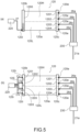
- the subsequent flow of the refrigerant will be described with reference to Parts (a) and (b) of Fig. 5 .
- Part (a) of Fig. 5 is a schematic block diagram describing the flow of a refrigerant according to this embodiment.
- Part (b) of Fig. 5 is a schematic block diagram describing the flow of a refrigerant according to Comparative Example.
- the gas-liquid two-phase refrigerant flowed into the header 120b of the second heat exchange part 120 is influenced by gravity to be separated into a liquid-phase refrigerant and a gas-phase refrigerant in the internal space 1200.
- a liquid-phase refrigerant with high density (dotted part in the figure) accumulates in the lower part of the internal space 1200, while the upper part of the internal space 1200 is filled with a gas-phase refrigerant with low density.
- a refrigerant with a relatively low degree of dryness mainly flows through the heat transfer tube provided in the low wind velocity region 120L, and a refrigerant with a relatively high degree of dryness mainly flows through the heat transfer tube provided in the high wind velocity region 120H.
- the refrigerant with a high degree of dryness releases more latent heat than the refrigerant with a low degree of dryness and is condensed.
- the refrigerant with a high degree of dryness which releases more latent heat, passes through the low wind velocity region 120L and the amount of heat exchange of the entire second heat exchange part 120 does not increase.
- the liquid-phase refrigerant formed by heat exchange between the gas-phase refrigerant and the high-speed indoor air mainly accumulates in the internal spaces 1201 and 1202 of the header 120c
- the liquid-phase refrigerant formed by heat exchange between the liquid-phase refrigerant and the low-speed indoor air mainly accumulates in the internal spaces 1203 and 1204 of the header 120c.
- liquid-phase refrigerant flowed into the pipe 26a from the internal space 1201 join together at the flow divider 230.
- the refrigerant joined together at the flow divider 230 flows through the pipe 21a as a liquid-phase refrigerant.
- the indoor heat exchanger 100 is not an integrated heat exchanger, but is divided into the first heat exchange part 110 and the second heat exchange part 120.
- the gas-phase refrigerant is condensed by the first heat exchange part 110 to become a gas-liquid two-phase refrigerant
- the gas-liquid two-phase refrigerant is condensed by the second heat exchange part 120 to become a liquid-phase refrigerant.
- the first heat exchange part 110 is not provided, the gas-phase refrigerant flows into the header 120b of the second heat exchange part 120. For this reason, a refrigerant cannot be separated into a liquid-phase refrigerant and a gas-phase refrigerant by gravity in the internal space 1200, and the function of the second heat exchange part 120 having the internal space 1200 cannot be exhibited.
- the inflow port 120i into which the gas-liquid two-phase refrigerant flows is disposed in the lower part of the header 120b in the direction of gravity.
- the inflow port 120i is disposed in the upper part of the header 120b in the direction of gravity, there is a possibility that a gas-liquid two-phase refrigerant with a low degree of dryness enters the heat transfer tube disposed in the high wind velocity region 120H and the amount of heat exchange of the high wind velocity region 120H decreases.
- the inflow port 120i is disposed in the lower part of the header 120b in the direction of gravity, the liquid-phase refrigerant accumulates in the lower part of the internal space 1200 and the gas-phase refrigerant accumulates in the upper part of the internal space 1200.
- the decrease in the amount of heat exchange between a refrigerant and air due to pressure loss is suppressed.
- the liquid-phase refrigerant flowed into the flow divider 230 from the pipe 21a is divided into the pipes 26a, 26b, 26c, and 26d, respectively.
- the liquid-phase refrigerant flowed into the internal space 1201 from the pipe 26a, the liquid-phase refrigerant flowed into the internal space 1202 from the pipe 26b, the liquid-phase refrigerant flowed into the internal space 1203 from the pipe 26c, and the liquid-phase refrigerant flowed into the internal space 1204 from the pipe 26d become a gas-liquid two-phase refrigerant by heat exchange with the indoor air in the body portion 120a, and flow into the internal space 1200 of the header 120b.
- the gas-liquid two-phase refrigerant flowed into the internal space 1200 is divided into the pipes 24a, 24b, 24c, 25a, 25b, and 25c by the flow divider 220 via the pipe 27.
- the gas-liquid two-phase refrigerant flowed into the internal space 1111 exchanges heat with the indoor air in the body portion 111a to become a gas-phase refrigerant, and flows into the internal space 1110 of the header 111b.
- the gas-liquid two-phase refrigerant flowed into the internal space 1112 exchanges heat with the indoor air in the body portion 111a to become a gas-phase refrigerant, and flows into the internal space 1110 of the header 111b.
- the gas-liquid two-phase refrigerant flowed into the internal space 1113 exchanges heat with the indoor air in the body portion 111a to become a gas-phase refrigerant, and flows into the internal space 1110 of the header 111b.
- the gas-liquid two-phase refrigerant flowed into the internal space 1121 exchanges heat with the indoor air in the body portion 112a to become a gas-phase refrigerant, and flows into the internal space 1120 of the header 112b.
- the gas-liquid two-phase refrigerant flowed into the internal space 1122 exchanges heat with the indoor air in the body portion 112a to become a gas-phase refrigerant, and flows into the internal space 1120 of the header 112b.
- the gas-liquid two-phase refrigerant flowed into the internal space 1123 exchanges heat with the indoor air in the body portion 112a to become a gas-phase refrigerant, and flows into the internal space 1120 of the header 112b.
- the gas-phase refrigerant in the header 111b flows into the flow divider 210 through the pipe 22, and the gas-phase refrigerant in the header 112b flows into the flow divider 210 through the pipe 23. After that, the gas-phase refrigerant flows through the pipe 21f.
- the gas-liquid two-phase refrigerant accumulated in the header 120b is appropriately diverted by the flow divider 220 into the upper heat exchange part 111 and also into the lower heat exchange part 112.
- a means for dividing the refrigerant in the header 111c or the header 112c without using the flow divider 220 may be provided, or a means for dividing the refrigerant in the header 120c without using the flow divider 230 may be provided.
- Each embodiment is not necessarily an independent form, and can be combined as far as technologically possible.
Landscapes
- Engineering & Computer Science (AREA)
- Mechanical Engineering (AREA)
- General Engineering & Computer Science (AREA)
- Physics & Mathematics (AREA)
- Thermal Sciences (AREA)
- Chemical & Material Sciences (AREA)
- Combustion & Propulsion (AREA)
- Heat-Exchange Devices With Radiators And Conduit Assemblies (AREA)
- Air Filters, Heat-Exchange Apparatuses, And Housings Of Air-Conditioning Units (AREA)
- Air-Flow Control Members (AREA)
Abstract
[Object] To suppress the decrease in the amount of heat exchange between a refrigerant and air due to pressure loss.
[Solving Means] In an indoor unit of an air conditioner, a second heat exchange part has a high wind velocity region where a wind velocity of air passing through the second heat exchange part is relatively high and a low wind velocity region where the wind velocity of air is relatively low, and the high wind velocity region is located above the low wind velocity region in a direction of gravity. At least one first heat transfer tube is disposed in the high wind velocity region, and at least one second heat transfer tube is disposed in the low wind velocity region. A first header is connected to each of the first heat transfer tube and the second heat transfer tube. The first header has a first internal space to which the first heat transfer tube and the second heat transfer tube are commonly connected. When using a heat exchanger as a condenser, the refrigerant flowed out from a first heat exchange part 110 flows into the first internal space of the first header, and then, the refrigerant flows into each of the first heat transfer tube and the second heat transfer tube from the first internal space.
Description
- The present invention relates to an indoor unit of an air conditioner that includes a heat exchanger.
- There is a heat exchanger that includes a plurality of heat transfer tubes lined up in parallel, a pair of headers connected to both ends of each of the plurality of heat transfer tubes, and a heat-dissipating fin that is provided between the pair of headers, the plurality of heat transfer tubes penetrating the heat-dissipating fin. In such a heat exchanger, when the air used for heat exchange passes therethrough, a region where the air flows quickly and a region where the air flows slowly are formed in some cases depending on the shape of the air passage in which the heat exchanger is provided.
- Under such circumstances, there is a technology that improves the amount of heat exchange between a refrigerant and air in the entire heat exchanger by adjusting the flow rate of the refrigerant in accordance with the flow velocity distribution of the air passing through the heat exchanger (see, for example, Patent Literature 1). In this technology, for example, by changing the heat transfer area of the region where the flow velocity of air is fast and the heat transfer area of the region where the flow velocity of air is slow, the circulation amount of the refrigerant in the region where the flow velocity of air is fast is increased to increase the amount of heat exchange and make the amount of heat exchange in the region where the flow velocity of air is fast closer to the amount of heat exchange in the region where the flow velocity of air is slow.
- Patent Literature 1:
Japanese Patent No. 5901748 - However, in the case where the heat transfer area in the region where the flow velocity of air is fast and the heat transfer area in the region where the flow velocity of air is slow are changed, the pressure loss in the refrigerant flow path increases as the flow velocity of the refrigerant increases in the region where the heat transfer area is reduced. As a result, in the region where the cross-sectional area of the flow path is small, the amount of heat exchange decreases.
- In view of the circumstances as described above, it is an object of the present invention to provide an indoor unit of an air conditioner that suppresses the decrease in the amount of heat exchange between a refrigerant and air due to pressure loss. Solution to Problem
- In order to achieve the above-mentioned object, an indoor unit of an air conditioner according to an embodiment of the present invention includes a heat exchanger that includes a first heat exchange part and a second heat exchange part.
- The second heat exchange part has a high wind velocity region where a wind velocity of air passing through the second heat exchange part is relatively high and a low wind velocity region where the wind velocity of air is relatively low, and the high wind velocity region is located above the low wind velocity region in a direction of gravity.
- At least one first heat transfer tube is disposed in the high wind velocity region, and at least one second heat transfer tube is disposed in the low wind velocity region.
- A first header is connected to each of the first heat transfer tube and the second heat transfer tube.
- The first header has a first internal space to which the first heat transfer tube and the second heat transfer tube are commonly connected.
- When using the heat exchanger as a condenser, the refrigerant flowed out from the first heat exchange part flows into the first internal space of the first header, and then the refrigerant flows into each of the first heat transfer tube and the second heat transfer tube from the first internal space.
- In accordance with such an indoor unit of an air conditioner, the decrease in the amount of heat exchange between a refrigerant and air due to pressure loss is suppressed.
- In the indoor unit of an air conditioner, the first header may be provided with an inflow port into which the refrigerant flowed out from the first heat exchange part flows, and the inflow port may be disposed in a lower part of the first header in the direction of gravity.
- In accordance with such an indoor unit of an air conditioner, the decrease in the amount of heat exchange between a refrigerant and air due to pressure loss is further suppressed.
- The indoor unit of an air conditioner may further include: a casing that houses the heat exchanger and includes an inlet port into which the air is inhaled and an outlet port from which the air is blown out; and an indoor fan that is housed in the casing, inhales in the air via the inlet port, and blows out the air that passes through the heat exchanger via the outlet port, the casing including a guide plate that guides the air that passes through the heat exchanger to the outlet port, the guide plate being provided between the low wind velocity region of the second heat exchange part and the fan.
- In accordance with such an indoor unit of an air conditioner, the decrease in the amount of heat exchange between a refrigerant and air due to pressure loss is further suppressed.
- The indoor unit of an air conditioner may further include a casing that houses the heat exchanger and includes an inlet port into which the air is inhaled and an outlet port from which the air is blown out, the casing including a drain pan that collects condensed water flowing down from the second heat exchange part, the low wind velocity region being located closer to the drain pan than the high wind velocity region.
- In accordance with such an indoor unit of an air conditioner, the decrease in the amount of heat exchange between a refrigerant and air due to pressure loss is further suppressed.
- In the indoor unit of an air conditioner, the first heat exchange part may include a second header that allows the refrigerant to flow out when the heat exchanger is used as a condenser, the second header may have a plurality of second internal spaces divided by at least one partition plate, and a volume of the first internal space may be larger than each of volumes of the plurality of second internal spaces.
- In accordance with such an indoor unit of an air conditioner, the decrease in the amount of heat exchange between a refrigerant and air due to pressure loss is further suppressed.
- In the indoor unit of an air conditioner, each of the plurality of second internal spaces may be connected to the first internal space via a pipe.
- In accordance with such an indoor unit of an air conditioner, the decrease in the amount of heat exchange between a refrigerant and air due to pressure loss is further suppressed.
- As described above, in accordance with the present invention, there is provided an indoor unit of an air conditioner that suppresses the decrease in the amount of heat exchange between a refrigerant and air due to pressure loss.
-
- [
Fig. 1 ] Part (a) ofFig. 1 is a schematic perspective view showing an overview of an air conditioner according to this embodiment. Part (b) ofFig. 1 is a schematic a block diagram showing an overview of a refrigerant circuit of the air conditioner according to this embodiment. - [
Fig. 2 ] Part (a) ofFig. 2 is an example of a schematic cross-sectional view of the indoor unit taken along the line A1-A2 in Part (a) ofFig. 1 . Part (b) ofFig. 2 is a schematic cross-sectional view of a secondheat exchange part 120 shown in Part (a) ofFig. 2 and the vicinity thereof. - [
Fig. 3] Fig. 3 is a schematic plan view of a heat exchange part according to this embodiment. - [
Fig. 4] Fig. 4 is a schematic block diagram showing how each of an upperheat exchange part 111 and a lowerheat exchange part 112 and the secondheat exchange part 120 are connected by pipes in an indoor heat exchanger. - [
Fig. 5 ] Part (a) ofFig. 5 is a schematic block diagram describing a flow of a refrigerant according to this embodiment. Part (b) ofFig. 5 is a schematic block diagram describing a flow of a refrigerant according to Comparative Example. - Embodiments of the present invention will be described below with reference to the drawings. Further, the same members or members having the same function are denoted by the same reference symbols in some cases, and the description is omitted as appropriate after the members are described. Further, when numerical values and numbers are illustrated below, the values are illustrative and are not limited to the numerical values and numbers.
- Part (a) of
Fig. 1 is a schematic perspective view showing an overview of an air conditioner according to this embodiment. Part (b) ofFig. 1 is a schematic block diagram showing an overview of a refrigerant circuit of the air conditioner according to this embodiment. An example of the air conditioner according to this embodiment is shown in Parts (a) and (b) ofFig. 1 , and the present invention is not limited to this example. In the following, "connection" means that a heat exchanger and a pressure reducing device, which are parts of a refrigerant circuit, are connected by a pipeline (pipe) shown by the solid line in Part (b) ofFig. 1 to form a refrigerant circuit. - As shown in Part (a) of
Fig. 1 , anair conditioner 1 includes anindoor unit 10 installed indoors and anoutdoor unit 30 installed outdoors. Theindoor unit 10 and theoutdoor unit 30 are connected to each other via apipe 21a and apipe 21f. Further, as shown in Part (b) ofFig. 1 , theair conditioner 1 includes acontrol device 40 in addition to theindoor unit 10 and theoutdoor unit 30. Theair conditioner 1 is an air conditioner that enables a cooling operation and a heating operation. - The
indoor unit 10 includes anindoor heat exchanger 100, atemperature sensor 140, and anindoor fan 150. Theindoor heat exchanger 100, thetemperature sensor 140, and theindoor fan 150 are housed in acasing 160 of theindoor unit 10 shown in Part (a) ofFig. 1 . Thecasing 160 includes atop plate 160t, aright side plate 160r, a left side plate 160l, abottom plate 160b, and a front plate (front panel) 160f. Each of these plates are formed of, for example, a resin. - The
indoor heat exchanger 100 shown in Part (b) ofFig. 1 is, for example, a heat exchanger that includes a plurality of metal fins and a plurality of heat transfer tubes. Thetemperature sensor 140 detects the temperature of air in the room to which theindoor unit 10 is attached. Examples of thetemperature sensor 140 include a thermocouple and a thermistor. A flow divider and a plurality of pipes, which are not shown in Part (b) ofFig. 1 , are disposed inside theindoor unit 10. Details of these will be described below. - The
outdoor unit 30 includes anoutdoor heat exchanger 300, acompressor 310, a four-way valve 320, apressure reducing device 330, atemperature sensor 340, and anoutdoor fan 350. Theoutdoor heat exchanger 300, thecompressor 310, the four-way valve 320, thepressure reducing device 330, thetemperature sensor 340, and theoutdoor fan 350 are housed in acasing 360 of theoutdoor unit 30 shown in Part (a) ofFig. 1 . - The
outdoor heat exchanger 300 shown in Part (b) ofFig. 1 includes, for example, a plurality of metal fins and a plurality of heat transfer tubes. Thepressure reducing device 330 is, for example, an expansion valve. - The
compressor 310 is connected between theindoor heat exchanger 100 and theoutdoor heat exchanger 300. Further, the four-way valve 320 is connected between theindoor heat exchanger 100 and thecompressor 310 and between theoutdoor heat exchanger 300 and thecompressor 310. - The
outdoor heat exchanger 300 is connected between the four-way valve 320 and thepressure reducing device 330. Thepressure reducing device 330 is connected between theoutdoor heat exchanger 300 and theindoor heat exchanger 100. The four-way valve 320, theoutdoor heat exchanger 300, and thepressure reducing device 330 are connecter in series. Theoutdoor fan 350 is disposed in the vicinity of theoutdoor heat exchanger 300. - The
temperature sensor 340 detects the temperature of theoutdoor heat exchanger 300. Examples of thetemperature sensor 340 include a thermocouple and a thermistor. - The
control device 40 controls theindoor unit 10 and theoutdoor unit 30. Thecontrol device 40 may be disposed in theoutdoor unit 30. Alternatively, part of thecontrol device 40 may be disposed in theoutdoor unit 30 and the remaining part may be disposed in theindoor unit 10. Further, in this embodiment, theindoor heat exchanger 100 is referred to simply as a heat exchanger in some cases. - The
pipe 21a connects theindoor heat exchanger 100 and thepressure reducing device 330 to each other. Apipe 21b connects thepressure reducing device 330 and theoutdoor heat exchanger 300 to each other. Apipe 21c connects theoutdoor heat exchanger 300 and the four-way valve 320 to each other. Apipe 21d connects the four-way valve 320 and thecompressor 310 to each other. Apipe 21e connects thecompressor 310 and the four-way valve 320 to each other. Thepipe 21f connects the four-way valve 320 and theindoor heat exchanger 100 to each other. - An operation of the
air conditioner 1 according to this embodiment will be described with reference to Part (b) ofFig. 1 . Theair conditioner 1 performs a heating operation in which theindoor heat exchanger 100 functions as a condenser and theoutdoor heat exchanger 300 functions as an evaporator, and a cooling operation in which theindoor heat exchanger 100 functions as an evaporator and theoutdoor heat exchanger 300 functions as a condenser. The heating operation and the cooling operation are switched by thecontrol device 40. Further, theair conditioner 1 is capable of performing a dehumidification operation in the same cooling cycle as that of the cooling operation. - In the case where the
air conditioner 1 performs a heating operation, a refrigerant circulates in the direction indicated by the broken line arrow. In the heating operation, theindoor heat exchanger 100 functions as a condenser, and theoutdoor heat exchanger 300 functions as an evaporator. - In the state of the heating operation, for example, the four-
way valve 320 is in the state indicated by the broken line, i.e., a port a and a port d of the four-way valve 320 communicate with each other and a port b and a port c of the four-way valve 320 communicate with each other. When thecompressor 310 is driven, the high-temperature and high-pressure gas-phase refrigerant discharged from thecompressor 310 flows into the four-way valve 320 through thepipe 21d and flows into theindoor unit 10 from the four-way valve 320 via thepipe 21f. The high-temperature and high-pressure gas-phase refrigerant flowed into theindoor unit 10 flows into theindoor heat exchanger 100, exchanges heat with the indoor air taken into theindoor unit 10 by rotation of theindoor fan 150, and is condensed to become a high-temperature and high-pressure liquid-phase refrigerant. - The high-temperature and high-pressure liquid-phase refrigerant flowed out from the
indoor heat exchanger 100 into thepipe 21a flows into theoutdoor unit 30. The high-temperature and high-pressure liquid-phase refrigerant flowed into theoutdoor unit 30 is depressurized via thepressure reducing device 330 whose degree of opening corresponds to the heating capacity to become a low-temperature and low-pressure gas-liquid two-phase refrigerant, and flows into theoutdoor heat exchanger 300 via thepipe 21b. The low-temperature and low-pressure gas-liquid two-phase refrigerant flowed into theoutdoor heat exchanger 300 exchanges heat with the outside air taken into theoutdoor unit 30 by rotation of theoutdoor fan 350, and evaporates to become a low-temperature and low-pressure gas-phase refrigerant. The low-temperature and low-pressure gas-phase refrigerant flowed out from theoutdoor heat exchanger 300 into thepipe 21c flows through the four-way valve 320, is inhaled into thecompressor 310, and is compressed again. - In the case where the
air conditioner 1 performs a cooling operation or a dehumidification operation, a refrigerant circulates in the direction indicated by the solid line arrow in theair conditioner 1. In the cooling operation, theoutdoor heat exchanger 300 functions as a condenser and theindoor heat exchanger 100 functions as an evaporator. - In the state of the cooling operation, the four-
way valve 320 is in the state indicated by the solid line, i.e., the port a and the port b of the four-way valve 320 communicate with each other, and the port c and the port d of the four-way valve 320 communicate with each other. When thecompressor 310 is driven, the high-temperature and high-pressure gas-phase refrigerant discharged from thecompressor 310 flows into the four-way valve 320 through thepipe 21d, and flows into theoutdoor heat exchanger 300 from the four-way valve 320 through thepipe 21c. The high-temperature and high-pressure gas-phase refrigerant flowed into theoutdoor heat exchanger 300 exchanges heat with the outside air taken into theoutdoor unit 30 by rotation of theoutdoor fan 350, and is condensed to become a high-temperature and high-pressure liquid-phase refrigerant. The high-temperature and high-pressure liquid-phase refrigerant flowed out from theoutdoor heat exchanger 300 into thepipe 21b is depressurized when passing through thepressure reducing device 330 whose degree of opening corresponds to the cooling capacity required during a cooling operation or the dehumidification capacity required during a dehumidification operation to become a low-temperature and low-pressure gas-liquid two-phase refrigerant, and flows into thepipe 21a. - The low-temperature and low-pressure gas-liquid two-phase refrigerant flowed into the
indoor unit 10 via thepipe 21a flows into theindoor heat exchanger 100, exchanges heat with the indoor air taken into theindoor unit 10 by rotation of theindoor fan 150, and evaporates to become a low-temperature and low-pressure gas-phase refrigerant. The low-temperature and low-pressure gas-phase refrigerant flowed out from theindoor heat exchanger 100 flows into the four-way valve 320 through thepipe 21f. The refrigerant flowed out from the four-way valve 320 is inhaled into thecompressor 310 via thepipe 21e and is compressed again. - The cross-sectional structure of the
indoor unit 10 will be described. Part (a) ofFig. 2 is an example of a schematic cross-sectional view of the indoor unit taken along the line A1-A2 in Part (a) ofFig. 1 . Part (b) ofFig. 2 is a schematic cross-sectional view of a secondheat exchange part 120 shown in Part (a) ofFig. 2 and the vicinity thereof. Theindoor unit 10 is installed on, for example, a wall surface in the room. - The
casing 160 included in theindoor unit 10 includes thetop plate 160t, theright side plate 160r, the left side plate 160l, thebottom plate 160b, thefront plate 160f, abase plate 161, and aframe plate 162. Thebase plate 161 is formed of, for example, a metal or a resin. Theframe plate 162 is formed of, for example, a resin. - In the
casing 160, thetop plate 160t forms the top surface of thecasing 160. Aninlet port 160i through which the indoor air is inhaled into theindoor unit 10 is provided in thetop plate 160t. Thebottom plate 160b forms the bottom surface of thecasing 160. Thebase plate 161 for attaching theindoor unit 10 to the wall surface is fixed to thebottom plate 160b. Thefront plate 160f is disposed to cover the front surface of thecasing 160. Further, theframe plate 162 that surrounds the lower part of a lowerheat exchange part 112 of a firstheat exchange part 110 is provided below thefront plate 160f. - An
outlet port 160e that blows out the indoor air exchanged heat with the refrigerant in theindoor heat exchanger 100 into the room is provided below theframe plate 162. Theoutlet port 160e is formed by the space sandwiched between thebase plate 161 and theframe plate 162. Further, the space connecting theinlet port 160i and theoutlet port 160e is defined as anair passage 160p. - The
indoor fan 150 is, for example, a crossflow fan formed of a resin material and is rotatably supported in theair passage 160p between theindoor heat exchanger 100 and theoutlet port 160e. Theindoor fan 150 is disposed in the middle of theair passage 160p. Theindoor fan 150 inhales the indoor air via theinlet port 160i. Then, theindoor fan 150 blows out the indoor air that passes through each of the firstheat exchange part 110 and the secondheat exchange part 120 via theoutlet port 160e. For example, when theindoor fan 150 rotates, the indoor air is inhaled into theair passage 160p through theinlet port 160i, and the indoor air is blown out from theair passage 160p through theoutlet port 160e. - The
indoor heat exchanger 100 is disposed on the side of thetop plate 160t and the side of thefront plate 160f when viewed from theindoor fan 150. Theindoor heat exchanger 100 includes the first heat exchange part 110 (first heat exchange part) and the second heat exchange part 120 (second heat exchange part). The firstheat exchange part 110 further includes an upperheat exchange part 111 and the lowerheat exchange part 112. The upperheat exchange part 111 includes aheat transfer tube 111p and afin 111f. The lowerheat exchange part 112 includes aheat transfer tube 112p and afin 112f. The secondheat exchange part 120 includes a heat transfer tube 120pa, a heat transfer tube 120pb, and afin 120f. - The upper
heat exchange part 111 of the firstheat exchange part 110 and the secondheat exchange part 120 are disposed above theindoor fan 150 in theair passage 160p, i.e., on the side of thetop plate 160t. Part of the upperheat exchange part 111 and part of the secondheat exchange part 120 face theindoor fan 150. The upperheat exchange part 111 of the firstheat exchange part 110 and the secondheat exchange part 120 are disposed in an inverted V shape with an acute angle in the cross section shown in Part (a) ofFig. 2 . - The lower
heat exchange part 112 of the firstheat exchange part 110 is disposed in front of theindoor fan 150, i.e., on the side of thefront plate 160f. The lowerheat exchange part 112 faces theindoor fan 150. In the cross section shown in Part (a) ofFig. 2 , the upperheat exchange part 111 and the lowerheat exchange part 112 are disposed to intersect at an obtuse angle. - Each of the upper
heat exchange part 111, the lowerheat exchange part 112, and the secondheat exchange part 120 is a microchannel type heat exchanger. For example, each of the upperheat exchange part 111, the lowerheat exchange part 112, and the secondheat exchange part 120 is formed by inserting a plurality of metal heat transfer tubes (flat tubes) into a plurality of metal fins. Further, each of the plurality of heat transfer tubes includes a minute flow path therein. Further, headers are connected to both ends of each of the plurality of heat transfer tubes (described below). - Further, the
casing 160 includes a drain pan that collects condensed water flowing down from the firstheat exchange part 110 or the secondheat exchange part 120. For example, the surface of theframe plate 162 on the side of the lowerheat exchange part 112 forms adrain pan 162d that receives condensed water generated in the firstheat exchange part 110. Further, the surface of thebase plate 161 on the side of the secondheat exchange part 120 forms adrain pan 161d that receives condensed water generated in the secondheat exchange part 120. - Further, the
casing 160 includes aguide plate 161g that smoothly guides the indoor air passes through theindoor heat exchanger 100 to theoutlet port 160e. For example, part of thebase plate 161 extends between theindoor fan 150 and the secondheat exchange part 120. This extending part is theguide plate 161g. - Further, the
outlet port 160e is provided with an up-downair deflector 163 that deflects the direction of the indoor air blown out from theoutlet port 160e in the up-and-down direction, and adiffuser 164. A right-leftair deflector 165 that deflects the direction of the indoor air blown out from theoutlet port 160e is provided on the upstream side of theoutlet port 160e of thediffuser 164. Further, afilter 166 that removes dust contained in the indoor air taken into theindoor unit 10 is provided between thefront plate 160f and theindoor heat exchanger 100. - In the
indoor unit 10, when theindoor fan 150 rotates, the flow of the indoor air passing through the secondheat exchange part 120 inside theindoor unit 10 is blocked by theguide plate 161g. As a result, as shown in Part (b) ofFig. 2 , the secondheat exchange part 120 has a highwind velocity region 120H where the wind velocity of the indoor air passing through the secondheat exchange part 120 is relatively high and a lowwind velocity region 120L where the wind velocity of the indoor air is relatively low. The highwind velocity region 120H is located above the lowwind velocity region 120L in the direction of gravity. The lowwind velocity region 120L is located closer to thedrain pan 161d than the highwind velocity region 120H. Theguide plate 161g is provided between the lowwind velocity region 120L and theindoor fan 150. - In the case where the first
heat exchange part 110 of theindoor heat exchanger 100 and the secondheat exchange part 120 function as condensers, the indoor air exchanged heat with the refrigerant in each of the firstheat exchange part 110 and the secondheat exchange part 120 is blown out from theoutlet port 160e into the room. As a result, the room in which theindoor unit 10 is installed is heated. - Part (a) of
Fig. 3 to Part (c) ofFig. 3 are each a schematic plan view of the heat exchange part according to this embodiment. Part (a) ofFig. 3 shows the upperheat exchange part 111 in the firstheat exchange part 110, Part (b) ofFig. 3 shows the lowerheat exchange part 112 in the firstheat exchange part 110. Part (c) ofFig. 3 shows the secondheat exchange part 120. In this embodiment, for example, when using theindoor heat exchanger 100 as a condenser (during a heating operation), a refrigerant flows into the firstheat exchange part 110, which is a pair of the upper heat exchange part 111 (Part (a) ofFig. 3 ) and the lower heat exchange part 112 (Part (b) ofFig. 3 ), and then the refrigerant flows into the second heat exchange part 120 (Part (c) ofFig. 3 ). That is, during a heating operation, the refrigerant flows through not a single heat exchanger but a plurality of heat exchange parts in a stepwise manner. Details of the flow of the refrigerant will be described with reference to the followingFig. 4 . - The upper
heat exchange part 111 shown in Part (a) ofFig. 3 includes abody portion 111a, and aheader 111b and aheader 111c that are disposed on both sides of thebody portion 111a and connected to thebody portion 111a. - The
body portion 111a includes a plurality offins 111f and at least oneheat transfer tube 111p (e.g., a plurality ofheat transfer tubes 111p). Each of the plurality offins 111f is disposed between theheader 111b and theheader 111c. Each of the plurality offins 111f extends in the longitudinal direction of each of theheader 111b and theheader 111c. Each of the plurality ofheat transfer tubes 111p is disposed substantially orthogonal to the plurality offins 111f. Each of the plurality ofheat transfer tubes 111p is inserted through the plurality offins 111f. - A pair of
headers heat transfer tubes 111p. For example, theheader 111b is connected to one end of each of the plurality ofheat transfer tubes 111p. Theheader 111c is connected to the other end of each of the plurality ofheat transfer tubes 111p. - In the upper
heat exchange part 111, theheader 111b has aninternal space 1110 to which the plurality ofheat transfer tubes 111p is commonly connected. Further, theheader 111c disposed on the opposite side of theheader 111b across thebody portion 111a has internal spaces divided by, for example, at least one partition plate. For example, Part (a) ofFig. 3 shows an example in which theheader 111c is divided into threeinternal spaces partition plates 111s. The dividedinternal spaces header 111c. - Further, the
header 111b is provided with aninflow port 111i that communicates with theinternal space 1110 and through which a refrigerant flows in during a heating operation. Theinflow port 111i serves as an outlet through which a refrigerant flows out during a cooling operation. Further, theheader 111c is provided with anoutflow port 111e that communicates with each of theinternal spaces outflow port 111e serves as an inflow port through which a refrigerant flows in during a cooling operation. - When using the
indoor heat exchanger 100 as a condenser (during a heating operation), a refrigerant flows into the upperheat exchange part 111 from theheader 111b, and the refrigerant flows out of the upperheat exchange part 111 via theheader 111c. - The lower
heat exchange part 112 shown in Part (b) ofFig. 3 includes abody portion 112a, and aheader 112b and aheader 112c that are disposed on both sides of thebody portion 112a and connected to thebody portion 112a. - The
body portion 112a includes a plurality offins 112f and at least oneheat transfer tube 112p (e.g., a plurality ofheat transfer tubes 112p). Each of the plurality offins 112f is disposed between theheader 112b and theheader 112c. Each of the plurality offins 112f extends in the longitudinal direction of each of theheader 112b and theheader 112c. Each of the plurality ofheat transfer tubes 112p is disposed substantially orthogonal to the plurality offins 112f. Each of the plurality ofheat transfer tubes 112p is inserted into the plurality offins 112f. - A pair of
headers heat transfer tubes 112p. For example, one end of each of the plurality ofheat transfer tubes 112p is connected to theheader 112b. The other end of each of the plurality ofheat transfer tubes 112p is connected to theheader 112c. - In the lower
heat exchange part 112, theheader 112b has aninternal space 1120 to which the plurality ofheat transfer tubes 112p is commonly connected. Further, theheader 112c disposed on the opposite side of theheader 112b across thebody portion 112a has an internal space divided by, for example, at least one partition plate. For example, Part (b) ofFig. 3 shows an example in which theheader 112c is divided into threeinternal spaces partition plates 112s. The dividedinternal spaces header 112c. - Further, the
header 112b is provided with aninflow port 112i that communicates with theinternal space 1120 and through which a refrigerant flows in during a heating operation. Theinflow port 112i serves as an outflow port through which a refrigerant flows out during a cooling operation. Further, theheader 112c is provided with anoutflow port 112e that communicates with each of theinternal spaces outflow port 112e serves as an inflow port through which a refrigerant flows in during a cooling operation. - When using the
indoor heat exchanger 100 as a condenser (during a heating operation), a refrigerant flows into the lowerheat exchange part 112 from theheader 112b, and the refrigerant flows out of the lowerheat exchange part 112 via theheader 112c. - Note that in this embodiment, the
header 111c or theheader 112c is used as a second header, and each of theinternal spaces internal spaces - The second
heat exchange part 120 shown in Part (c) ofFig. 3 includes abody portion 120a, and aheader 120b (first header) and aheader 120c that are disposed on both sides of thebody portion 120a and connected to thebody portion 120a. - The
body portion 120a includes a plurality offins 120f, at least one heat transfer tube 120pa (first heat transfer tube), and at least one heat transfer tube 120pb (second heat transfer tube). Each of the plurality offins 120f is disposed between theheader 120b and theheader 120c and extends in the longitudinal direction of each of theheader 120b and theheader 120c. The at least one heat transfer tube 120pa (e.g., a plurality of heat transfer tubes 120pa) is disposed in the highwind velocity region 120H of the secondheat exchange part 120. The at least one heat transfer tube 120pb (e.g., a plurality of heat transfer tubes 120pb) is disposed in the lowwind velocity region 120L of the secondheat exchange part 120. Each of the plurality of heat transfer tubes 120pa and each of the plurality of heat transfer tubes 120pb are disposed substantially orthogonal to the plurality offins 120f. Each of the plurality of heat transfer tubes 120pb is inserted into the plurality offins 120f. - A pair of
headers header 120b is connected to one end of each of the plurality of heat transfer tubes 120pa and one end of each of the plurality of heat transfer tubes 120pb. Theheader 120c is connected to the other end of each of the plurality of heat transfer tubes 120pa and the other end of each of the plurality of heat transfer tubes 120pb. - In the second
heat exchange part 120, theheader 120b has an internal space 1200 (first internal space) to which the plurality of heat transfer tubes 120pa and the plurality of heat transfer tubes 120pb are commonly connected. The volume of theinternal space 1200 is larger than the volume of each of theinternal spaces internal spaces internal space 1200 decreases, and two-phase separation easily occurs in theinternal space 1200. - Further, the
header 120c disposed on the opposite side of theheader 120b across thebody portion 120a has, for example, an internal space divided into a plurality of spaces. For example, Part (c) ofFig. 3 shows an example in which theheader 120c is divided into fourinternal spaces partition plates 120s. The dividedinternal spaces header 120c. - Further, the
header 120b is provided with aninflow port 120i that communicates with theinternal space 1200 and through which a refrigerant flows in during a heating operation. For example, during a heating operation, the refrigerant flowed out from the firstheat exchange part 110 flows into theinflow port 120i. Theinflow port 120i serves as an outflow port through which a refrigerant flows out during a cooling operation. Theinflow port 120i is disposed in the lower part of theheader 120b in the direction of gravity. For example, theinflow port 120i is disposed in the lowwind velocity region 120L at a position furthest from the highwind velocity region 120H in the longitudinal direction of theheader 120b. - Further, the
header 120c is provided with anoutflow port 120e that communicates with each of theinternal spaces outflow port 120e serves as an inflow port through which a refrigerant flows in during a cooling operation. - When using the
indoor heat exchanger 100 as a condenser (during a heating operation), the refrigerant flowed out from the firstheat exchange part 110 flows into theinternal space 1200 of theheader 120b. After that, the refrigerant flowed into theinternal space 1200 flows into each of the heat transfer tube 120pa and the heat transfer tube 120pb from theinternal space 1200. Further, the refrigerant flows out of the secondheat exchange part 120 via theheader 120c. -
Fig. 4 is a schematic block diagram showing how each of the upperheat exchange part 111 and the lowerheat exchange part 112 and the secondheat exchange part 120 are connected by pipes in the indoor heat exchanger. Here, the state of a heating operation (theindoor heat exchanger 100 is used as a condenser) is when a refrigerant flows from the side of thepipe 21f to the side of thepipe 21a, and the state of a cooling operation (theindoor heat exchanger 100 is used as an evaporator) is when a refrigerant flows from the side of thepipe 21a to the side of thepipe 21f. - As shown in
Fig. 4 , theindoor unit 10 includes aflow divider 210, aflow divider 220, aflow divider 230, apipe 22, apipe 23,pipes pipes pipes pipe 27 in addition to theindoor heat exchanger 100 and theindoor fan 150. - As shown in
Fig. 4 , thepipe 21f is branched into thepipe 22 and thepipe 23 by theflow divider 210 just before the firstheat exchange part 110. Onepipe 22 branched from theflow divider 210 connects theflow divider 210 to theinflow port 111i provided in theheader 111b of the upperheat exchange part 111. Theother pipe 23 branched from theflow divider 210 connects theflow divider 210 to theinflow port 112i provided in theheader 112b of the lowerheat exchange part 112. - For example, a plurality of
pipes header 111c provided on the opposite side of theheader 111b. Thepipe 24a connects theoutflow port 111e connected to aninternal space 1111 to theflow divider 220. Thepipe 24b connects theoutflow port 111e connected to aninternal space 1112 to theflow divider 220. Thepipe 24c connects theoutflow port 111e connected to aninternal space 1113 to theflow divider 220. Thepipe 24a, thepipe 24b, and thepipe 24c connected to theheader 111c are disposed to merge into theflow divider 220. - Further, for example, a plurality of
pipes header 112c of the lowerheat exchange part 112. Thepipe 25a connects theoutflow port 112e connected to aninternal space 1121 to theflow divider 220. Thepipe 25b connects theoutflow port 112e connected to aninternal space 1122 to theflow divider 220. Thepipe 25c connects theoutflow port 112e connected to aninternal space 1123 to theflow divider 220. Thepipe 25a, thepipe 25b, and thepipe 25c connected to theheader 112c are disposed to merge into theflow divider 220. - The
flow divider 220 and theheader 120b of the secondheat exchange part 120 are connected by thepipe 27. As a result, theinternal space 1111 is connected to theinternal space 1200 via thepipe 24a, theflow divider 220, and thepipe 27, theinternal space 1112 is connected to theinternal space 1200 via thepipe 24b, theflow divider 220, and thepipe 27, and theinternal space 1113 is connected to theinternal space 1200 via thepipe 24c, theflow divider 220, and thepipe 27. Further, theinternal space 1121 is connected to theinternal space 1200 via thepipe 25a, theflow divider 220, and thepipe 27, theinternal space 1122 is connected to theinternal space 1200 via thepipe 25b, theflow divider 220, and thepipe 27, and theinternal space 1123 is connected to theinternal space 1200 via thepipe 25c, theflow divider 220, and thepipe 27. - Further, for example, a plurality of
pipes header 120c provided on the opposite side of theheader 120b. Thepipe 26a connects theoutflow port 120e connected to aninternal space 1201 to theflow divider 230. Thepipe 26b connects theoutflow port 120e connected to aninternal space 1202 to theflow divider 230. Thepipe 26c connects theoutflow port 120e connected to aninternal space 1203 to theflow divider 230. Thepipe 26d connects theoutflow port 120e connected to aninternal space 1204 to theflow divider 230. Thepipe 26a, thepipe 26b, thepipe 26c, and thepipe 26d connected to theheader 120c are disposed to merge into theflow divider 230. Further, thepipe 21a is connected to theflow divider 230. - The flow of a refrigerant in the
indoor unit 10 will be described using an example of a heating operation. - During a heating operation, a refrigerant flows from the
pipe 21f to thepipe 21a, and theindoor heat exchanger 100 disposed between thepipe 21f and thepipe 21a functions as a condenser. During a heating operation, a gas-phase refrigerant flows into theindoor heat exchanger 100 from thepipe 21f. After that, the refrigerant flowing through theindoor heat exchanger 100 and the indoor air taken into theindoor unit 10 exchange heat with each other, and the refrigerant is condensed in theindoor heat exchanger 100 to become a two-phase gas-liquid state and then liquefy. After that, the liquid-phase refrigerant flows out from theindoor heat exchanger 100 into thepipe 21a. The flow of a refrigerant inFig. 4 will be described below with the refrigerant in the gas phase as a gas-phase refrigerant, the refrigerant in the gas-liquid two-phase as a gas-liquid two-phase refrigerant, and the refrigerant in the liquid phase as a liquid-phase refrigerant. - For example, the gas-phase refrigerant flowing through the
pipe 21f is divided into thepipe 22 and thepipe 23 by theflow divider 210. - Next, the gas-phase refrigerant flowing through the
pipe 22 flows into theheader 111b of the upperheat exchange part 111. Since the refrigerant in the gas phase flows into theinternal space 1110 of theheader 111b, the gas-phase refrigerant is uniformly dispersed in theinternal space 1110 without being affected by gravity. That is, in theinternal space 1110 into which a gas-phase refrigerant flows, even if theinternal space 1110 is not divided by a partition plate, it is possible to allow a refrigerant to uniformly flow into the plurality ofheat transfer tubes 111p connected to theinternal space 1110. - Next, the gas-phase refrigerant and the indoor air exchange heat with each other in the
body portion 111a of the upperheat exchange part 111, and part of the gas-phase refrigerant is condensed in thebody portion 111a to become a gas-liquid two-phase refrigerant. After that, the gas-liquid two-phase refrigerant formed in thebody portion 111a flows into each of theinternal spaces header 111c. - The gas-liquid two-phase refrigerants flowed into the
internal spaces flow divider 220 and flow through thepipe 27. The gas-liquid two-phase refrigerant flowing through thepipe 27 flows into theheader 120b of the secondheat exchange part 120. - Meanwhile, the gas-phase refrigerant flowing through the
pipe 23 flows into theheader 112b of the lowerheat exchange part 112. Since the refrigerant in the gas phase flows into theinternal space 1120 of theheader 112b, the gas-phase refrigerant is uniformly dispersed in theinternal space 1120. - Next, the gas-phase refrigerant and the indoor air exchange heat with each other in the
body portion 112a of the lowerheat exchange part 112, and part of the gas-phase refrigerant is condensed in thebody portion 112a to become a gas-liquid two-phase refrigerant. After that, the gas-liquid two-phase refrigerant formed in thebody portion 112a flows into each of theinternal spaces header 112c. - The gas-liquid two-phase refrigerant flowed into the
internal spaces flow divider 220 and flow through thepipe 27. The gas-liquid two-phase refrigerant flowing through thepipe 27 flows into theheader 120b of the secondheat exchange part 120. - In this way, the gas-phase refrigerant before flowing into the first heat exchange part 110 (the upper
heat exchange part 111, the lower heat exchange part 112) becomes a gas-liquid two-phase refrigerant in the firstheat exchange part 110, and this gas-liquid two-phase refrigerant flows into theheader 120b of the secondheat exchange part 120. The subsequent flow of the refrigerant will be described with reference to Parts (a) and (b) ofFig. 5 . - Part (a) of
Fig. 5 is a schematic block diagram describing the flow of a refrigerant according to this embodiment. Part (b) ofFig. 5 is a schematic block diagram describing the flow of a refrigerant according to Comparative Example. - As shown in Part (a) of
Fig. 5 , the gas-liquid two-phase refrigerant flowed into theheader 120b of the secondheat exchange part 120 is influenced by gravity to be separated into a liquid-phase refrigerant and a gas-phase refrigerant in theinternal space 1200. For example, a liquid-phase refrigerant with high density (dotted part in the figure) accumulates in the lower part of theinternal space 1200, while the upper part of theinternal space 1200 is filled with a gas-phase refrigerant with low density. - As a result, a refrigerant with a relatively low degree of dryness mainly flows through the heat transfer tube provided in the low
wind velocity region 120L, and a refrigerant with a relatively high degree of dryness mainly flows through the heat transfer tube provided in the highwind velocity region 120H. Here, the refrigerant with a high degree of dryness releases more latent heat than the refrigerant with a low degree of dryness and is condensed. Therefore, the high-speed indoor air which flow through the highwind velocity region 120H and the refrigerant with a high degree of dryness exchange heat with each other, the low-speed indoor air which flow through the lowwind velocity region 120L and the refrigerant with a low degree of dryness exchange heat with each other, and thus, the amount of heat exchange (the amount of heat released from the secondheat exchange part 120 to the indoor air or the amount of heat absorbed by the indoor air from the second heat exchange part 120) of the entire secondheat exchange part 120 including the highwind velocity region 120H and the lowwind velocity region 120L increases. That is, the amount of indoor air passing through thebody portion 120a is greater in the highwind velocity region 120H than the lowwind velocity region 120L. For this reason, when the refrigerant with a high degree of dryness, which releases more latent heat and is condensed, passes through the highwind velocity region 120H, heat release to the indoor air increases and the amount of heat exchange in the highwind velocity region 120H increases. As a result, the amount of heat exchange of the entire secondheat exchange part 120 increases. - Conversely, if the high-speed indoor air which flow through the high
wind velocity region 120H and the refrigerant with a low degree of dryness exchange heat with each other and the low-speed indoor air which flow through the lowwind velocity region 120L and the refrigerant with a high degree of dryness exchange heat with each other, the refrigerant with a high degree of dryness, which releases more latent heat, passes through the lowwind velocity region 120L and the amount of heat exchange of the entire secondheat exchange part 120 does not increase. - Here, as shown in Comparative Example shown in Part (b) of
Fig. 5 , when a plurality ofpipes flow divider 220 and theheader 120b of the secondheat exchange part 120 is divided into a plurality ofinternal spaces flow divider 220 is evenly divided into theinternal space 1201 via thepipe 27a, theinternal space 1202 via thepipe 27b, theinternal space 1203 via thepipe 27c, and theinternal space 1204 via thepipe 27d, respectively. - Therefore, a gas-liquid two-phase refrigerant with the same degree of dryness flows through both the high
wind velocity region 120H and the lowwind velocity region 120L, and thus, the refrigerant with a high degree of dryness, which releases more latent heat and is condensed, cannot be caused to flow through the highwind velocity region 120H. As a result, the amount of heat exchange of the entire secondheat exchange part 120 does not increase. - Further, there is also a method of changing the volumes of the
internal space 1201, theinternal space 1202, theinternal space 1203, and theinternal space 1204 depending on the wind velocity distribution of the indoor air passing through the secondheat exchange part 120, generating a flow velocity difference by changing the number of heat transfer tubes 120pa to be connected, and increasing the amount of heat exchange by increasing the circulation amount of the refrigerant in the highwind velocity region 120H. However, in the region where the number of heat transfer tubes 120pa to be connected is reduced, the pressure loss in the refrigerant flow path increases as the flow velocity of the refrigerant increases. As a result, in the region where the cross-sectional area of the flow path is small, the amount of heat exchange decreases. On the other hand, in this embodiment, it is possible to suppress the increase in pressure loss in the refrigerant flow path without dividing theinternal space 1200 into a plurality of internal spaces. - After that, in this embodiment, the liquid-phase refrigerant formed by heat exchange between the gas-phase refrigerant and the high-speed indoor air mainly accumulates in the
internal spaces header 120c, and the liquid-phase refrigerant formed by heat exchange between the liquid-phase refrigerant and the low-speed indoor air mainly accumulates in theinternal spaces header 120c. Further, the liquid-phase refrigerant flowed into thepipe 26a from theinternal space 1201, the liquid-phase refrigerant flowed into thepipe 26b from theinternal space 1202, the liquid-phase refrigerant flowed into thepipe 26c from theinternal space 1203, and the liquid-phase refrigerant flowed into thepipe 26d from theinternal space 1204 join together at theflow divider 230. Then, the refrigerant joined together at theflow divider 230 flows through thepipe 21a as a liquid-phase refrigerant. - Further, in this embodiment, the
indoor heat exchanger 100 is not an integrated heat exchanger, but is divided into the firstheat exchange part 110 and the secondheat exchange part 120. As a result, during a heating operation, the gas-phase refrigerant is condensed by the firstheat exchange part 110 to become a gas-liquid two-phase refrigerant, and the gas-liquid two-phase refrigerant is condensed by the secondheat exchange part 120 to become a liquid-phase refrigerant. Here, if the firstheat exchange part 110 is not provided, the gas-phase refrigerant flows into theheader 120b of the secondheat exchange part 120. For this reason, a refrigerant cannot be separated into a liquid-phase refrigerant and a gas-phase refrigerant by gravity in theinternal space 1200, and the function of the secondheat exchange part 120 having theinternal space 1200 cannot be exhibited. - Further, in this embodiment, the
inflow port 120i into which the gas-liquid two-phase refrigerant flows is disposed in the lower part of theheader 120b in the direction of gravity. Here, if theinflow port 120i is disposed in the upper part of theheader 120b in the direction of gravity, there is a possibility that a gas-liquid two-phase refrigerant with a low degree of dryness enters the heat transfer tube disposed in the highwind velocity region 120H and the amount of heat exchange of the highwind velocity region 120H decreases. On the other hand, in this embodiment, since theinflow port 120i is disposed in the lower part of theheader 120b in the direction of gravity, the liquid-phase refrigerant accumulates in the lower part of theinternal space 1200 and the gas-phase refrigerant accumulates in the upper part of theinternal space 1200. - As described above, in accordance with this embodiment, the decrease in the amount of heat exchange between a refrigerant and air due to pressure loss is suppressed.
- Further, in this embodiment, when stitching from a heating operation to a cooling operation, the liquid-phase refrigerant flowed into the
flow divider 230 from thepipe 21a is divided into thepipes internal space 1201 from thepipe 26a, the liquid-phase refrigerant flowed into theinternal space 1202 from thepipe 26b, the liquid-phase refrigerant flowed into theinternal space 1203 from thepipe 26c, and the liquid-phase refrigerant flowed into theinternal space 1204 from thepipe 26d become a gas-liquid two-phase refrigerant by heat exchange with the indoor air in thebody portion 120a, and flow into theinternal space 1200 of theheader 120b. - Next, in a cooling operation, the gas-liquid two-phase refrigerant flowed into the
internal space 1200 is divided into thepipes flow divider 220 via thepipe 27. After that, the gas-liquid two-phase refrigerant flowed into theinternal space 1111 exchanges heat with the indoor air in thebody portion 111a to become a gas-phase refrigerant, and flows into theinternal space 1110 of theheader 111b. The gas-liquid two-phase refrigerant flowed into theinternal space 1112 exchanges heat with the indoor air in thebody portion 111a to become a gas-phase refrigerant, and flows into theinternal space 1110 of theheader 111b. The gas-liquid two-phase refrigerant flowed into theinternal space 1113 exchanges heat with the indoor air in thebody portion 111a to become a gas-phase refrigerant, and flows into theinternal space 1110 of theheader 111b. Meanwhile, the gas-liquid two-phase refrigerant flowed into theinternal space 1121 exchanges heat with the indoor air in thebody portion 112a to become a gas-phase refrigerant, and flows into theinternal space 1120 of theheader 112b. The gas-liquid two-phase refrigerant flowed into theinternal space 1122 exchanges heat with the indoor air in thebody portion 112a to become a gas-phase refrigerant, and flows into theinternal space 1120 of theheader 112b. The gas-liquid two-phase refrigerant flowed into theinternal space 1123 exchanges heat with the indoor air in thebody portion 112a to become a gas-phase refrigerant, and flows into theinternal space 1120 of theheader 112b. - In the cooling operation, after that, the gas-phase refrigerant in the
header 111b flows into theflow divider 210 through thepipe 22, and the gas-phase refrigerant in theheader 112b flows into theflow divider 210 through thepipe 23. After that, the gas-phase refrigerant flows through thepipe 21f. - In this way, in the case of using the
indoor heat exchanger 100 as an evaporator, the gas-liquid two-phase refrigerant accumulated in theheader 120b is appropriately diverted by theflow divider 220 into the upperheat exchange part 111 and also into the lowerheat exchange part 112. - Further, in this embodiment, it is not necessary to divide the
header 120b of the secondheat exchange part 120 as in Comparative Example (Part (b) ofFig. 5 ). As a result, it is possible to suppress the increase in cost by the amount for not dividing theheader 120b of the secondheat exchange part 120. - Although an embodiment of the present invention has been described, it goes without saying that the present invention is not limited to the above-mentioned embodiment and various modifications can be made. For example, a means for dividing the refrigerant in the
header 111c or theheader 112c without using theflow divider 220 may be provided, or a means for dividing the refrigerant in theheader 120c without using theflow divider 230 may be provided. Each embodiment is not necessarily an independent form, and can be combined as far as technologically possible. -
- 1 air conditioner
- 10 indoor unit
- 21a, 21b, 21c, 21d, 21e, 21f, 22, 23, 24a, 24b, 24c, 25a, 25b, 25c, 26a, 26b, 26c, 26d, 27 pipe
- 30 outdoor unit
- 40 control device
- 100 indoor heat exchanger
- 110, 120 heat exchange part
- 111 upper heat exchange part
- 112 lower heat exchange part
- 111a, 112a, 120a body portion
- 111b, 111c, 112b, 112c, 120b, 120c header
- 111e, 112e, 120e outflow port
- 111f, 112f, 120f fin
- 111i, 112i, 120i inflow port
- 111s, 112s, 120s partition plate
- 111p, 112p, 120p heat transfer tube
- 120H high wind velocity region
- 120L low wind velocity region
- 140 temperature sensor
- 150 indoor fan
- 160, 360 casing
- 160t top plate
- 160b bottom plate
- 160l left side plate
- 160r right side plate
- 160f front plate
- 160i inlet port
- 160p air passage
- 160e outlet port
- 161 base plate
- 161d drain pan
- 161g guide plate
- 162 frame plate
- 162d drain pan
- 163 up-down air deflector
- 164 diffuser
- 165 right-left air deflector
- 166 filter
- 210, 220, 230 flow divider
- 300 outdoor heat exchanger
- 310 compressor
- 320 four-way valve
- 330 pressure reducing device
- 340 temperature sensor
- 350 outdoor fan
- 110, 1111, 1112, 1113, 1120, 1121, 1122, 1123, 1200, 1201, 1202, 1203, 1204 internal space
Claims (6)
- An indoor unit of an air conditioner, comprising:a heat exchanger that includes a first heat exchange part and a second heat exchange part, whereinthe second heat exchange part has a high wind velocity region where a wind velocity of air passing through the second heat exchange part is relatively high and a low wind velocity region where the wind velocity of air is relatively low, and the high wind velocity region is located above the low wind velocity region in a direction of gravity,at least one first heat transfer tube is disposed in the high wind velocity region, and at least one second heat transfer tube is disposed in the low wind velocity region,a first header is connected to each of the first heat transfer tube and the second heat transfer tube,the first header has a first internal space to which the first heat transfer tube and the second heat transfer tube are commonly connected,the refrigerant flowed out from the first heat exchange part flows into the first internal space of the first header, and then the refrigerant flows into each of the first heat transfer tube and the second heat transfer tube from the first internal space when the heat exchanger is used as a condenser.
- The indoor unit of an air conditioner according to claim 1, whereinthe first header is provided with an inflow port into which the refrigerant flowed out from the first heat exchange part flows, andthe inflow port is disposed in a lower part of the first header in the direction of gravity.
- The indoor unit of an air conditioner according to claim 1 or 2, further comprisinga casing that houses the heat exchanger and includes an inlet port into which the air is inhaled and an outlet port from which the air is blown out; andan indoor fan that is housed in the casing, inhales the air via the inlet port, and blows out the air that passes through the heat exchanger via the outlet port,the casing including a guide plate that guides the air that passes through the heat exchanger to the outlet port,the guide plate being provided between the low wind velocity region of the second heat exchange part and the fan.
- The indoor unit of an air conditioner according to claim 1 or 2, further comprisinga casing that houses the heat exchanger and includes an inlet port into which the air is inhaled and an outlet port from which the air is blown out,the casing including a drain pan that collects condensed water flowing down from the second heat exchange part,the low wind velocity region being located closer to the drain pan than the high wind velocity region.
- The indoor unit of an air conditioner according to any one of claims 1 to 4, whereinthe first heat exchange part includes a second header that allows the refrigerant to flow out when the heat exchanger is used as a condenser,the second header has a plurality of second internal spaces divided by at least one partition plate, anda volume of the first internal space is larger than each of volumes of the plurality of second internal spaces.
- The indoor unit of an air conditioner according to claim 5, wherein
each of the plurality of second internal spaces is connected to the first internal space via a pipe.
Applications Claiming Priority (2)
| Application Number | Priority Date | Filing Date | Title |
|---|---|---|---|
| JP2022056160A JP7392757B2 (en) | 2022-03-30 | 2022-03-30 | Air conditioner indoor unit |
| PCT/JP2023/011751 WO2023190121A1 (en) | 2022-03-30 | 2023-03-24 | Indoor unit for air conditioner |
Publications (1)
| Publication Number | Publication Date |
|---|---|
| EP4502504A1 true EP4502504A1 (en) | 2025-02-05 |
Family
ID=88201377
Family Applications (1)
| Application Number | Title | Priority Date | Filing Date |
|---|---|---|---|
| EP23780131.1A Pending EP4502504A1 (en) | 2022-03-30 | 2023-03-24 | Indoor unit for air conditioner |
Country Status (6)
| Country | Link |
|---|---|
| US (1) | US20250207787A1 (en) |
| EP (1) | EP4502504A1 (en) |
| JP (1) | JP7392757B2 (en) |
| CN (1) | CN118922669A (en) |
| AU (1) | AU2023242980B2 (en) |
| WO (1) | WO2023190121A1 (en) |
Families Citing this family (1)
| Publication number | Priority date | Publication date | Assignee | Title |
|---|---|---|---|---|
| WO2026045172A1 (en) * | 2024-08-30 | 2026-03-05 | 青岛海信日立空调系统有限公司 | Air purification module, air conditioner, total heat exchanger, and air conditioning system |
Family Cites Families (15)
| Publication number | Priority date | Publication date | Assignee | Title |
|---|---|---|---|---|
| US5678417A (en) * | 1995-06-28 | 1997-10-21 | Kabushiki Kaisha Toshiba | Air conditioning apparatus having dehumidifying operation function |
| JP4845943B2 (en) | 2008-08-26 | 2011-12-28 | 三菱電機株式会社 | Finned tube heat exchanger and refrigeration cycle air conditioner |
| JP5371365B2 (en) | 2008-10-20 | 2013-12-18 | 東芝キヤリア株式会社 | Air conditioner indoor unit |
| JP2010133656A (en) | 2008-12-05 | 2010-06-17 | Sharp Corp | Indoor unit of air conditioner |
| JP2012037099A (en) | 2010-08-04 | 2012-02-23 | Sharp Corp | Indoor unit of air conditioner |
| CN104272040B (en) | 2012-04-26 | 2016-06-15 | 三菱电机株式会社 | Refrigerant distributor, possess the heat exchanger of this refrigerant distributor, freezing cycle device and air conditioner |
| JP6371046B2 (en) | 2013-09-03 | 2018-08-08 | 日立ジョンソンコントロールズ空調株式会社 | Air conditioner and heat exchanger for air conditioner |
| WO2015063853A1 (en) | 2013-10-29 | 2015-05-07 | 株式会社日立製作所 | Refrigeration cycle and air conditioner |
| WO2016178278A1 (en) | 2015-05-01 | 2016-11-10 | 三菱電機株式会社 | Layered header, heat exchanger, and air conditioner |
| JP6742112B2 (en) | 2016-02-29 | 2020-08-19 | 三菱重工サーマルシステムズ株式会社 | Heat exchanger and air conditioner |
| WO2017208493A1 (en) | 2016-06-03 | 2017-12-07 | 日立ジョンソンコントロールズ空調株式会社 | Air conditioner |
| JP6704361B2 (en) | 2017-01-13 | 2020-06-03 | 日立ジョンソンコントロールズ空調株式会社 | Air conditioner |
| JP2019027699A (en) | 2017-07-31 | 2019-02-21 | ダイキン工業株式会社 | Heat exchanger and heat exchanger manufacturing method |
| JP2019152367A (en) | 2018-03-02 | 2019-09-12 | パナソニックIpマネジメント株式会社 | Heat exchange unit and air conditioner using the same |
| JP7470909B2 (en) | 2020-02-03 | 2024-04-19 | 東芝ライフスタイル株式会社 | Microchannel heat exchanger and air conditioner |
-
2022
- 2022-03-30 JP JP2022056160A patent/JP7392757B2/en active Active
-
2023
- 2023-03-24 EP EP23780131.1A patent/EP4502504A1/en active Pending
- 2023-03-24 WO PCT/JP2023/011751 patent/WO2023190121A1/en not_active Ceased
- 2023-03-24 US US18/846,277 patent/US20250207787A1/en active Pending
- 2023-03-24 AU AU2023242980A patent/AU2023242980B2/en active Active
- 2023-03-24 CN CN202380029683.0A patent/CN118922669A/en active Pending
Also Published As
| Publication number | Publication date |
|---|---|
| WO2023190121A1 (en) | 2023-10-05 |
| CN118922669A (en) | 2024-11-08 |
| JP2023148248A (en) | 2023-10-13 |
| JP7392757B2 (en) | 2023-12-06 |
| AU2023242980A1 (en) | 2024-09-05 |
| AU2023242980B2 (en) | 2026-04-30 |
| US20250207787A1 (en) | 2025-06-26 |
Similar Documents
| Publication | Publication Date | Title |
|---|---|---|
| US10677503B2 (en) | Heat exchanger | |
| EP3203175B1 (en) | Heat exchanger and air conditioning apparatus | |
| EP3088832B1 (en) | Heat exchanger and air conditioning device | |
| JP4178472B2 (en) | Heat exchanger and air conditioner | |
| JP2003254555A (en) | Air conditioner | |
| CN113551314B (en) | Horizontal condenser, outdoor unit and air conditioning system | |
| AU2023242980B2 (en) | Indoor unit for air conditioner | |
| WO2017208493A1 (en) | Air conditioner | |
| JP2006097987A (en) | Three-way branch pipe and fin tube heat exchanger using the same | |
| JP4952347B2 (en) | Air conditioner | |
| JP3298432B2 (en) | Heat exchanger | |
| EP4060251B1 (en) | Heat exchanger | |
| JP2015052439A (en) | Heat exchanger | |
| JP3851403B2 (en) | Indoor unit for air conditioner | |
| JP6590957B2 (en) | Refrigeration equipment | |
| JP2018048769A (en) | Heat exchanger | |
| JP7224535B1 (en) | heat exchangers and air conditioners | |
| JP4300502B2 (en) | Parallel flow type heat exchanger for air conditioning | |
| EP3734190A1 (en) | Heat exchanger and refrigeration cycle device | |
| JPH1151412A (en) | Indoor unit for air conditioner and its indoor heat exchanger | |
| JP6869382B2 (en) | Air conditioner | |
| KR20180080879A (en) | Heat exchanger | |
| CN117355721A (en) | Heat exchanger, outdoor unit of air-conditioning device provided with heat exchanger, and air-conditioning device provided with outdoor unit of air-conditioning device | |
| KR20220019932A (en) | Outdoor unit of air conditioner | |
| JP7401800B2 (en) | Refrigeration cycle equipment |
Legal Events
| Date | Code | Title | Description |
|---|---|---|---|
| STAA | Information on the status of an ep patent application or granted ep patent |
Free format text: STATUS: THE INTERNATIONAL PUBLICATION HAS BEEN MADE |
|
| PUAI | Public reference made under article 153(3) epc to a published international application that has entered the european phase |
Free format text: ORIGINAL CODE: 0009012 |
|
| STAA | Information on the status of an ep patent application or granted ep patent |
Free format text: STATUS: REQUEST FOR EXAMINATION WAS MADE |
|
| 17P | Request for examination filed |
Effective date: 20240830 |
|
| AK | Designated contracting states |
Kind code of ref document: A1 Designated state(s): AL AT BE BG CH CY CZ DE DK EE ES FI FR GB GR HR HU IE IS IT LI LT LU LV MC ME MK MT NL NO PL PT RO RS SE SI SK SM TR |
|
| DAV | Request for validation of the european patent (deleted) | ||
| DAX | Request for extension of the european patent (deleted) |