EP4501720A1 - Vorrichtung zur steuerung des verhaltens eines sattelfahrzeugs und steuerungsverfahren - Google Patents
Vorrichtung zur steuerung des verhaltens eines sattelfahrzeugs und steuerungsverfahren Download PDFInfo
- Publication number
- EP4501720A1 EP4501720A1 EP23717236.6A EP23717236A EP4501720A1 EP 4501720 A1 EP4501720 A1 EP 4501720A1 EP 23717236 A EP23717236 A EP 23717236A EP 4501720 A1 EP4501720 A1 EP 4501720A1
- Authority
- EP
- European Patent Office
- Prior art keywords
- straddle
- type vehicle
- positional relationship
- state
- target
- Prior art date
- Legal status (The legal status is an assumption and is not a legal conclusion. Google has not performed a legal analysis and makes no representation as to the accuracy of the status listed.)
- Pending
Links
Images


Classifications
-
- B—PERFORMING OPERATIONS; TRANSPORTING
- B60—VEHICLES IN GENERAL
- B60W—CONJOINT CONTROL OF VEHICLE SUB-UNITS OF DIFFERENT TYPE OR DIFFERENT FUNCTION; CONTROL SYSTEMS SPECIALLY ADAPTED FOR HYBRID VEHICLES; ROAD VEHICLE DRIVE CONTROL SYSTEMS FOR PURPOSES NOT RELATED TO THE CONTROL OF A PARTICULAR SUB-UNIT
- B60W30/00—Purposes of road vehicle drive control systems not related to the control of a particular sub-unit, e.g. of systems using conjoint control of vehicle sub-units
- B60W30/14—Adaptive cruise control
- B60W30/16—Control of distance between vehicles, e.g. keeping a distance to preceding vehicle
-
- B—PERFORMING OPERATIONS; TRANSPORTING
- B60—VEHICLES IN GENERAL
- B60W—CONJOINT CONTROL OF VEHICLE SUB-UNITS OF DIFFERENT TYPE OR DIFFERENT FUNCTION; CONTROL SYSTEMS SPECIALLY ADAPTED FOR HYBRID VEHICLES; ROAD VEHICLE DRIVE CONTROL SYSTEMS FOR PURPOSES NOT RELATED TO THE CONTROL OF A PARTICULAR SUB-UNIT
- B60W30/00—Purposes of road vehicle drive control systems not related to the control of a particular sub-unit, e.g. of systems using conjoint control of vehicle sub-units
- B60W30/18—Propelling the vehicle
- B60W30/182—Selecting between different operative modes, e.g. comfort and performance modes
-
- B—PERFORMING OPERATIONS; TRANSPORTING
- B60—VEHICLES IN GENERAL
- B60T—VEHICLE BRAKE CONTROL SYSTEMS OR PARTS THEREOF; BRAKE CONTROL SYSTEMS OR PARTS THEREOF, IN GENERAL; ARRANGEMENT OF BRAKING ELEMENTS ON VEHICLES IN GENERAL; PORTABLE DEVICES FOR PREVENTING UNWANTED MOVEMENT OF VEHICLES; VEHICLE MODIFICATIONS TO FACILITATE COOLING OF BRAKES
- B60T7/00—Brake-action initiating means
- B60T7/12—Brake-action initiating means for automatic initiation; for initiation not subject to will of driver or passenger
- B60T7/22—Brake-action initiating means for automatic initiation; for initiation not subject to will of driver or passenger initiated by contact of vehicle, e.g. bumper, with an external object, e.g. another vehicle, or by means of contactless obstacle detectors mounted on the vehicle
-
- B—PERFORMING OPERATIONS; TRANSPORTING
- B60—VEHICLES IN GENERAL
- B60T—VEHICLE BRAKE CONTROL SYSTEMS OR PARTS THEREOF; BRAKE CONTROL SYSTEMS OR PARTS THEREOF, IN GENERAL; ARRANGEMENT OF BRAKING ELEMENTS ON VEHICLES IN GENERAL; PORTABLE DEVICES FOR PREVENTING UNWANTED MOVEMENT OF VEHICLES; VEHICLE MODIFICATIONS TO FACILITATE COOLING OF BRAKES
- B60T8/00—Arrangements for adjusting wheel-braking force to meet varying vehicular or ground-surface conditions, e.g. limiting or varying distribution of braking force
- B60T8/17—Using electrical or electronic regulation means to control braking
- B60T8/1701—Braking or traction control means specially adapted for particular types of vehicles
- B60T8/1706—Braking or traction control means specially adapted for particular types of vehicles for single-track vehicles, e.g. motorcycles
-
- B—PERFORMING OPERATIONS; TRANSPORTING
- B60—VEHICLES IN GENERAL
- B60W—CONJOINT CONTROL OF VEHICLE SUB-UNITS OF DIFFERENT TYPE OR DIFFERENT FUNCTION; CONTROL SYSTEMS SPECIALLY ADAPTED FOR HYBRID VEHICLES; ROAD VEHICLE DRIVE CONTROL SYSTEMS FOR PURPOSES NOT RELATED TO THE CONTROL OF A PARTICULAR SUB-UNIT
- B60W30/00—Purposes of road vehicle drive control systems not related to the control of a particular sub-unit, e.g. of systems using conjoint control of vehicle sub-units
- B60W30/14—Adaptive cruise control
- B60W30/143—Speed control
-
- B—PERFORMING OPERATIONS; TRANSPORTING
- B60—VEHICLES IN GENERAL
- B60W—CONJOINT CONTROL OF VEHICLE SUB-UNITS OF DIFFERENT TYPE OR DIFFERENT FUNCTION; CONTROL SYSTEMS SPECIALLY ADAPTED FOR HYBRID VEHICLES; ROAD VEHICLE DRIVE CONTROL SYSTEMS FOR PURPOSES NOT RELATED TO THE CONTROL OF A PARTICULAR SUB-UNIT
- B60W30/00—Purposes of road vehicle drive control systems not related to the control of a particular sub-unit, e.g. of systems using conjoint control of vehicle sub-units
- B60W30/14—Adaptive cruise control
- B60W30/16—Control of distance between vehicles, e.g. keeping a distance to preceding vehicle
- B60W30/165—Automatically following the path of a preceding lead vehicle, e.g. "electronic tow-bar"
-
- B—PERFORMING OPERATIONS; TRANSPORTING
- B60—VEHICLES IN GENERAL
- B60T—VEHICLE BRAKE CONTROL SYSTEMS OR PARTS THEREOF; BRAKE CONTROL SYSTEMS OR PARTS THEREOF, IN GENERAL; ARRANGEMENT OF BRAKING ELEMENTS ON VEHICLES IN GENERAL; PORTABLE DEVICES FOR PREVENTING UNWANTED MOVEMENT OF VEHICLES; VEHICLE MODIFICATIONS TO FACILITATE COOLING OF BRAKES
- B60T2201/00—Particular use of vehicle brake systems; Special systems using also the brakes; Special software modules within the brake system controller
- B60T2201/02—Active or adaptive cruise control system; Distance control
- B60T2201/022—Collision avoidance systems
-
- B—PERFORMING OPERATIONS; TRANSPORTING
- B60—VEHICLES IN GENERAL
- B60W—CONJOINT CONTROL OF VEHICLE SUB-UNITS OF DIFFERENT TYPE OR DIFFERENT FUNCTION; CONTROL SYSTEMS SPECIALLY ADAPTED FOR HYBRID VEHICLES; ROAD VEHICLE DRIVE CONTROL SYSTEMS FOR PURPOSES NOT RELATED TO THE CONTROL OF A PARTICULAR SUB-UNIT
- B60W2300/00—Indexing codes relating to the type of vehicle
- B60W2300/36—Cycles; Motorcycles; Scooters
-
- B—PERFORMING OPERATIONS; TRANSPORTING
- B60—VEHICLES IN GENERAL
- B60W—CONJOINT CONTROL OF VEHICLE SUB-UNITS OF DIFFERENT TYPE OR DIFFERENT FUNCTION; CONTROL SYSTEMS SPECIALLY ADAPTED FOR HYBRID VEHICLES; ROAD VEHICLE DRIVE CONTROL SYSTEMS FOR PURPOSES NOT RELATED TO THE CONTROL OF A PARTICULAR SUB-UNIT
- B60W2554/00—Input parameters relating to objects
- B60W2554/40—Dynamic objects, e.g. animals, windblown objects
- B60W2554/404—Characteristics
- B60W2554/4041—Position
-
- B—PERFORMING OPERATIONS; TRANSPORTING
- B60—VEHICLES IN GENERAL
- B60W—CONJOINT CONTROL OF VEHICLE SUB-UNITS OF DIFFERENT TYPE OR DIFFERENT FUNCTION; CONTROL SYSTEMS SPECIALLY ADAPTED FOR HYBRID VEHICLES; ROAD VEHICLE DRIVE CONTROL SYSTEMS FOR PURPOSES NOT RELATED TO THE CONTROL OF A PARTICULAR SUB-UNIT
- B60W2554/00—Input parameters relating to objects
- B60W2554/80—Spatial relation or speed relative to objects
- B60W2554/801—Lateral distance
-
- B—PERFORMING OPERATIONS; TRANSPORTING
- B60—VEHICLES IN GENERAL
- B60W—CONJOINT CONTROL OF VEHICLE SUB-UNITS OF DIFFERENT TYPE OR DIFFERENT FUNCTION; CONTROL SYSTEMS SPECIALLY ADAPTED FOR HYBRID VEHICLES; ROAD VEHICLE DRIVE CONTROL SYSTEMS FOR PURPOSES NOT RELATED TO THE CONTROL OF A PARTICULAR SUB-UNIT
- B60W2554/00—Input parameters relating to objects
- B60W2554/80—Spatial relation or speed relative to objects
- B60W2554/802—Longitudinal distance
-
- B—PERFORMING OPERATIONS; TRANSPORTING
- B60—VEHICLES IN GENERAL
- B60W—CONJOINT CONTROL OF VEHICLE SUB-UNITS OF DIFFERENT TYPE OR DIFFERENT FUNCTION; CONTROL SYSTEMS SPECIALLY ADAPTED FOR HYBRID VEHICLES; ROAD VEHICLE DRIVE CONTROL SYSTEMS FOR PURPOSES NOT RELATED TO THE CONTROL OF A PARTICULAR SUB-UNIT
- B60W2754/00—Output or target parameters relating to objects
- B60W2754/10—Spatial relation or speed relative to objects
-
- B—PERFORMING OPERATIONS; TRANSPORTING
- B60—VEHICLES IN GENERAL
- B60Y—INDEXING SCHEME RELATING TO ASPECTS CROSS-CUTTING VEHICLE TECHNOLOGY
- B60Y2200/00—Type of vehicle
- B60Y2200/10—Road Vehicles
- B60Y2200/12—Motorcycles, Trikes; Quads; Scooters
Definitions
- the present invention relates to a controller for behavior of a straddle-type vehicle and a control method for behavior of a straddle-type vehicle.
- a conventional controller for behavior of a straddle-type vehicle acquires positional relationship information between a traveling straddle-type vehicle and a target, and executes positional relationship adjustment operation to automatically change a travel speed of the straddle-type vehicle on the basis of the positional relationship information, and to adjust a positional relationship between the straddle-type vehicle and the target (for example, see PTL 1).
- a body of the straddle-type vehicle is much smaller than those of other vehicles (for example, a passenger car, a truck, and the like).
- other vehicles for example, a passenger car, a truck, and the like.
- plural straddle-type vehicles travel in line and/or side by side in a unique positional relationship (for example, a situation where the plural straddle-type vehicles travel side by side in a single travel lane, a situation where the plural straddle-type vehicles travel while forming plural vehicle lines in the single travel lane, or the like) .
- the invention has been made with the above-described problem as the background and therefore obtains a controller capable of improving assistance performance for a rider.
- the invention also obtains a control method capable of improving the assistance performance for the rider.
- a controller is a controller for behavior of a straddle-type vehicle and includes: an acquisition section that acquires positional relationship information between the traveling straddle-type vehicle and a target; and an execution section that executes positional relationship adjustment operation to automatically change a travel speed of the straddle-type vehicle on the basis of the positional relationship information acquired by the acquisition section and to thereby adjust a positional relationship between the straddle-type vehicle and the target.
- the execution section switches between a first operation mode in which the positional relationship between the straddle-type vehicle and the target is brought into a first state and a second operation mode in which the positional relationship between the straddle-type vehicle and the target is brought into a second state differing from the first state according to whether a group travel mode is valid.
- the group travel mode is a mode in which the straddle-type vehicle travels with at least one other straddle-type vehicle in a group.
- a control method is a control method for behavior of a straddle-type vehicle and includes: an acquisition step in which an acquisition section of a controller acquires positional relationship information between the traveling straddle-type vehicle and a target; and an execution step in which an execution section of the controller executes positional relationship adjustment operation to automatically change a travel speed of the straddle-type vehicle on the basis of the positional relationship information acquired in the acquisition step and to thereby adjust a positional relationship between the straddle-type vehicle and the target.
- the execution section switches between a first operation mode in which the positional relationship between the straddle-type vehicle and the target is brought into a first state and a second operation mode in which the positional relationship between the straddle-type vehicle and the target is brought into a second state differing from the first state according to whether a group travel mode is valid.
- the group travel mode is a mode in which the straddle-type vehicle travels with at least one other straddle-type vehicle in a group.
- the first operation mode in which the positional relationship between the straddle-type vehicle and the target is brought into the first state
- the second operation mode in which the positional relationship between the straddle-type vehicle and the target is brought into the second state differing from the first state
- the group travel mode is the mode in which the straddle-type vehicle travels with the at least one other straddle-type vehicle in the group. Therefore, it is possible to execute the appropriate positional relationship adjustment operation under a situation where the plural straddle-type vehicles travel in line or side by side in a unique positional relationship, and it is thus possible to improve assistance performance for a rider.
- the controller and the control method according to the invention are used for a rider-assistance system of a two-wheeled motor vehicle.
- the controller and the control method according to the invention may be used for a rider-assistance system of a straddle-type vehicle other than the two-wheeled motor vehicle.
- the straddle-type vehicle means a vehicle that a rider drives while straddling a body thereof.
- Examples of the straddle-type vehicle are motorcycles (the two-wheeled motor vehicle and a three-wheeled motor vehicle) and a pedal-driven vehicle.
- the motorcycles include a vehicle having an engine as a power source, a vehicle having an electric motor as the power source, and the like.
- the motorcycles are a motorbike, a scooter, and an electric scooter.
- the pedal-driven vehicle means a vehicle capable of traveling forward on a road by a depression force applied to pedals by the rider.
- Examples of the pedal-driven vehicle are a normal pedal-driven vehicle, an electrically-assisted pedal-driven vehicle, and an electric pedal-driven vehicle.
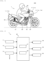
- Fig. 1 is a view illustrating a mounted state of the rider-assistance system according to the embodiment of the invention to the straddle-type vehicle.
- Fig. 2 is a diagram illustrating a system configuration of the rider-assistance system according to the embodiment of the invention.
- Fig. 3 to Fig. 7 are views for explaining the configuration of the rider-assistance system according to the embodiment of the invention.
- a rider-assistance system 1 is mounted to a straddle-type vehicle 100.
- the rider-assistance system 1 includes a surrounding environment sensor 11, a vehicle behavior sensor 12, a setting input device 13, a controller (ECU) 20, a brake system 30, a drive system 40, and a notification device 50.
- ECU controller
- the controller 20 executes rider-assistance operation to assist with driving by a rider of the straddle-type vehicle 100 by using output of the surrounding environment sensor 11 and the vehicle behavior sensor 12 and output of the setting input device 13.
- the controller 20 executes the rider-assistance operation by outputting commands to the various devices (for example, the brake system 30, the drive system 40, the notification device 50, and the like).
- the controller 20 receives output of various sensors (not illustrated) for detecting other types of information (for example, information on an operation state of the brake system 30 by the rider, information on an operation state of the drive system 40 by the rider, and the like).
- Each component of the rider-assistance system 1 may exclusively be used for the rider-assistance system 1 or may be shared with another system.
- the surrounding environment sensor 11 may be a surrounding environment sensor 11a that faces the front of the straddle-type vehicle 100, may be a surrounding environment sensor 11b that faces the rear of the straddle-type vehicle 100, may be a surrounding environment sensor 11c that faces the left of the straddle-type vehicle 100, may be a surrounding environment sensor 11d that faces the right of the straddle-type vehicle 100, or may be a combination of those.
- Examples of the surrounding environment sensors 11a, 11b, 11c, 11d are a radar, a Lidar sensor, an ultrasonic sensor, and a camera. At least one part of the surrounding environment sensor 11c and the surrounding environment sensor 11d may be substituted by the surrounding environment sensor 11a or the surrounding environment sensor 11b.
- Examples of the vehicle behavior sensor 12 are a vehicle speed sensor and an inertial measurement unit (IMU).
- the vehicle speed sensor detects a speed generated to the straddle-type vehicle 100.
- the vehicle speed sensor may detect another physical quantity that can substantially be converted to a travel speed of the straddle-type vehicle 100.
- the IMU detects acceleration in three axes (a front-rear direction, a vehicle width direction, and a vehicle height direction) and angular velocities in three axes (roll, pitch, and yaw) generated to the straddle-type vehicle 100.
- the IMU may detect other physical quantities that can substantially be converted to the three-axis acceleration and the three-axis angular velocities generated to the straddle-type vehicle 100.
- the IMU may partially detect the three-axis acceleration and the three-axis angular velocities.
- the setting input device 13 accepts input of various settings by the rider.
- the rider can switch between validity and invalidity of each of various types of the rider-assistance operation by using the setting input device 13.
- the rider can set various modes or various threshold values that are used for the various types of the rider-assistance operation by using the setting input device 13.
- the setting input device 13 may accept an operation by the rider's body (for example, a hand, a foot, or the like) or may accept voice produced by the rider.
- the setting input device 13 may be provided to the straddle-type vehicle 100 or may be provided to an accessory (for example, a helmet, a glove, or the like) that is associated with the straddle-type vehicle 100.
- the controller 20 at least includes an acquisition section 21 and an execution section 22.
- the sections of the controller 20 may collectively be provided in a single casing or may separately be provided in plural casings.
- the controller 20 as a whole or each of the sections of the controller 20 may be a microcomputer, a microprocessor unit, or the like, may be one whose firmware and the like can be updated, or may be a program module or the like that is executed by a command from a CPU or the like, for example.
- the acquisition section 21 acquires surrounding environment information of the straddle-type vehicle 100 on the basis of the output of the surrounding environment sensor 11.
- the surrounding environment information includes positional relationship information between the straddle-type vehicle 100 and a vehicle that travels around the straddle-type vehicle 100. Examples of the positional relationship information are information on a relative position, a relative distance, a relative speed, relative acceleration, relative jerk, a passing time difference, and a predicted time until a collision.
- the positional relationship information may be information on another physical quantity that can substantially be converted to one of those.
- the execution section 22 determines a target from the vehicles traveling around the straddle-type vehicle 100 on the basis of the positional relationship information acquired by the acquisition section 21. In the case where the validated positional relationship adjustment operation is intended to assist with driving by the rider in response to an event that occurs in front of the straddle-type vehicle 100, the execution section 22 determines, as the target, the vehicle that travels ahead of the straddle-type vehicle 100. In the case where the validated positional relationship adjustment operation is intended to assist with driving by the rider in response to an event that occurs behind the straddle-type vehicle 100, the execution section 22 determines, as the target, the vehicle that follows the straddle-type vehicle 100.
- the execution section 22 executes the positional relationship adjustment operation to automatically change the travel speed of the straddle-type vehicle 100 on the basis of the positional relationship information between the straddle-type vehicle 100 and the target that is acquired by the acquisition section 21 and to thereby adjust a positional relationship between the straddle-type vehicle 100 and the target.
- the positional relationship adjustment operation is operation to adjust the positional relationship in the front-rear direction of a travel lane.
- the execution section 22 automatically changes the travel speed of the straddle-type vehicle 100 by outputting the command to the brake system 30 or the drive system 40.
- the brake system 30 brakes the straddle-type vehicle 100.
- the drive system 40 as a power source of the straddle-type vehicle 100 drives the straddle-type vehicle 100.
- the brake system 30 may be controlled to generate or increase deceleration of the straddle-type vehicle 100 or may be controlled to generate or increase the acceleration of the straddle-type vehicle 100.
- the drive system 40 may be controlled to generate or increase the acceleration of the straddle-type vehicle 100 or may be controlled to generate or increase the deceleration of the straddle-type vehicle 100.
- the positional relationship adjustment operation may be operation to automatically generate the deceleration or the acceleration to the straddle-type vehicle 100 without relying on the rider's operation of the brake system 30 and the drive system 40 and to thereby adjust the positional relationship between the straddle-type vehicle 100 and the target (for example, adaptive cruise control operation to set the target as a speed following target, operation to decelerate or accelerate the straddle-type vehicle 100 in order to avoid or mitigate a collision against the target, operation to actuate the brake system 30 in a state where the rider operates the drive system 40 in order to control the positional relationship with the target to the positional relationship corresponding to an operation amount of the drive system 40, operation to actuate the drive system 40 in a state where the rider operates the brake system 30 in order to control the positional relationship with the target to the positional relationship corresponding to an operation amount of the brake system 30, or the like), may be operation to automatically increase or reduce a braking force generated to the straddle-type vehicle 100 in order to correct excess or defici
- the execution section 22 causes the notification device 50 to execute notification operation for the rider as necessary.
- the notification device 50 may notify the rider by display (that is, a sensation through a visual organ as a sensory organ), may notify the rider by sound (that is, a sensation through an auditory organ as the sensory organ), or may notify the rider by vibrations (that is, a sensation through a tactile organ as the sensory organ). Examples of the notification device 50 are a display, a lamp, a speaker, and a vibrator.
- the notification device 50 may be provided to the straddle-type vehicle 100 or may be provided to the accessory (for example, the helmet, the glove, or the like) that is associated with the straddle-type vehicle 100.
- the execution section 22 determines, as a target 200, the vehicle that travels ahead of the straddle-type vehicle 100 or the vehicle that follows the straddle-type vehicle 100.
- the execution section 22 stores a state amount set S1 as illustrated in Fig. 4 .
- the state amount set S1 plural state amounts P, each of which defines the positional relationship between the straddle-type vehicle 100 and the target 200, are combined.
- Fig. 4 illustrates a case where the state amount P is the passing time difference.
- the state amount P may be another state amount such as the relative distance or the predicted time until the collision.
- the rider of the straddle-type vehicle 100 can set whether to adjust the positional relationship between the straddle-type vehicle 100 and the target 200 to have an approaching tendency or to adjust the positional relationship between the straddle-type vehicle 100 and the target 200 to have a separating tendency.
- the rider of the straddle-type vehicle 100 can select a degree of the adjustment of the positional relationship between the straddle-type vehicle 100 and the target 200 from plural levels.
- Fig. 4 illustrates a case where the rider of the straddle-type vehicle 100 selects from five levels that are Lv 1 to Lv 5. However, the number of the levels may differ.
- Lv 1 corresponds a case where the positional relationship between the straddle-type vehicle 100 and the target 200 is adjusted to have the most approaching tendency
- Lv 5 corresponds a case where the positional relationship between the straddle-type vehicle 100 and the target 200 is adjusted to have the most separating tendency.
- the acquisition section 21 acquires, as setting input information, information on setting with the setting input device 13 on the basis of the output of the setting input device 13.
- the execution section 22 selects the state amount P that corresponds to the setting input information (that is, Lv information) from the state amount set S1, controls the travel speed of the straddle-type vehicle 100 so as to obtain such a state amount P, and thereby adjusts the positional relationship between the straddle-type vehicle 100 and the target 200.
- the execution section 22 controls such that an absolute value of a first-order derivative and/or an absolute value of a second-order derivative of the travel speed generated to the straddle-type vehicle 100 does not exceed a limit value.
- the limit value may be the same or different between a case where the first-order derivative and/or the second-order derivative of the travel speed generated to the straddle-type vehicle 100 is a positive value and a case where the first-order derivative and/or the second-order derivative of the travel speed generated to the straddle-type vehicle 100 is a negative value.
- the execution section 22 may control such that the first-order derivative and/or the second-order derivative of the travel speed generated to the straddle-type vehicle 100 does not exceed the limit value only when the first-order derivative and/or the second-order derivative is the positive value, may control such that the first-order derivative and/or the second-order derivative of the travel speed generated to the straddle-type vehicle 100 does not exceed the limit value only when the first-order derivative and/or the second-order derivative is the negative value, or may control to achieve both of those.
- the execution section 22 controls distribution of the braking force to front and rear wheels of the straddle-type vehicle 100 to a predetermined ratio when outputting the command to the brake system 30 so as to execute the positional relationship adjustment operation.
- the execution section 22 determines whether the group travel mode is valid.
- the group travel mode is a mode in which the straddle-type vehicle 100 travels with at least one other straddle-type vehicle 300 in a group, that is, in a team.
- the execution section 22 automatically switches between the validity and the invalidity of the group travel mode on the basis of the surrounding environment information that is acquired by the acquisition section 21.
- the execution section 22 determines whether the group travel mode is valid on the basis of information on the switchover.
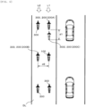
- the execution section 22 determines whether travel of the straddle-type vehicle 100 and the other straddle-type vehicle 300, which is located around the straddle-type vehicle 100, in a particular aspect (for example, an aspect as illustrated in Fig. 5 in which two vehicle lines are formed such that the straddle-type vehicle 100 and the plural other straddle-type vehicles 300 travel in a zig-zag arrangement, an aspect as illustrated in Fig.
- the execution section 22 automatically validates the group travel mode.
- the execution section 22 may identify the other straddle-type vehicle 300 that is located in a travel lane DL in which the straddle-type vehicle 100 travels, and may only set the identified other straddle-type vehicle 300 as a determination target.
- the execution section 22 may identify the other straddle-type vehicle 300 that remains located around the straddle-type vehicle 100 over the reference time or the reference travel distance without using information on a boundary of the travel lane DL, and may set the identified other straddle-type vehicle 300 as the determination target.
- the validity or the invalidity of the group travel mode is switched by the rider's setting input.
- the acquisition section 21 acquires information on the setting as the setting input information on the basis of the output of the setting input device 13.
- the execution section 22 determines whether the group travel mode is valid on the basis of the setting input information.
- the execution section 22 may automatically suggest to validate and/or invalidate the group travel mode on the basis of the surrounding environment information that is acquired by the acquisition section 21, and the suggestion may be confirmed by the rider's setting input of acceptance.
- the execution section 22 executes the different positional relationship adjustment operation from that in the normal state, that is, the state where it is determined that the group travel mode is not valid.
- the positional relationship adjustment operation is operation to adjust the positional relationship in the front-rear direction of the travel lane DL.
- the validated positional relationship adjustment operation is intended to assist with driving by the rider in response to the event that occurs in front of or on the side of the straddle-type vehicle 100 and where the execution section 22 adjusts the positional relationship with the other straddle-type vehicle 300 that travels ahead of the straddle-type vehicle 100 or the other straddle-type vehicle 300 that travels side by side with the straddle-type vehicle 100.
- the execution section 22 adjusts the positional relationship with the other straddle-type vehicle 300, which follows the straddle-type vehicle 100, by a similar method.
- the execution section 22 Based on the surrounding environment information acquired by the acquisition section 21, the execution section 22 identifies the other straddle-type vehicle 300, which travels with the straddle-type vehicle 100 in the group, from vehicles located around the straddle-type vehicle 100.
- a determination on whether the other straddle-type vehicle 300 is a vehicle that travels with the straddle-type vehicle 100 in the group may be made on the basis of information that is registered by the rider in advance (for example, location information of the straddle-type vehicle 100 in the group, identification information of the other straddle-type vehicle 300 that belongs to the group, or the like), or may be made on the basis of information on time course of the positional relationship with the straddle-type vehicle 100.
- the execution section 22 determines, as the target 200 (denoted as 200A in Fig. 5 and Fig. 6 ), the other straddle-type vehicle 300 that belongs to a first vehicle line L1, to which the straddle-type vehicle 100 in the group belongs, and that travels ahead of the straddle-type vehicle 100 at the nearest location to the straddle-type vehicle 100.
- the execution section 22 determines, as the target 200 (denoted as 200B in Fig. 5 and Fig.
- the execution section 22 identifies to which of the right and left vehicle lines in the travel lane DL the straddle-type vehicle 100 belongs on the basis of the information that is registered by the rider in advance (for example, the location information of the straddle-type vehicle 100 in the group, or the like) or on the basis of the information on the time course of the positional relationship with each of the plural other straddle-type vehicles 300, that is, uses group vehicle line information. In this way, the execution section 22 can identify the other straddle-type vehicle 300 that belongs to the first vehicle line L1 and the other straddle-type vehicle 300 that belongs to the second vehicle line L2.
- the execution section 22 Based on the surrounding environment information that is acquired by the acquisition section 21, the execution section 22 identifies the other straddle-type vehicles 300, each of which travels with the straddle-type vehicle 100 in the group, from the vehicles that are located around the straddle-type vehicle 100.
- the determination on whether the other straddle-type vehicles 300 are the vehicles, each of which travels with the straddle-type vehicle 100 in the group, may be made on the basis of the information that is registered by the rider in advance (for example, the location information of the straddle-type vehicle 100 in the group, the identification information of the other straddle-type vehicles 300 that belong to the group, and the like), or may be made on the basis of the information on the time course of the positional relationship with the straddle-type vehicle 100.
- the execution section 22 determines, as the target 200 (denoted as 200C in Fig. 5 and Fig. 6 ), a single imaginary vehicle 300I that represents the other straddle-type vehicle 300 belonging to the first vehicle line L1, to which the straddle-type vehicle 100 in the group belongs, and traveling ahead of the straddle-type vehicle 100 at the nearest location to the straddle-type vehicle 100 and the other straddle-type vehicle 300 belonging to the second vehicle line L2, to which the straddle-type vehicle 100 in the group does not belong, and traveling ahead of or side by side with the straddle-type vehicle 100 at the nearest location to the straddle-type vehicle 100.
- the execution section 22 identifies to which of the right and left vehicle lines in the travel lane DL the straddle-type vehicle 100 belongs on the basis of the information that is registered by the rider in advance (for example, information on the travel location of the straddle-type vehicle 100 in the group, or the like) or on the basis of the information on the time course of the positional relationship with each of the plural other straddle-type vehicles 300, that is, uses the group vehicle line information. In this way, the execution section 22 can identify the other straddle-type vehicle 300 that belongs to the first vehicle line L1 and the other straddle-type vehicle 300 that belongs to the second vehicle line L2.
- the imaginary vehicle 300I is a vehicle that is imagined as the other straddle-type vehicle 300 (denoted as 200A in Fig. 5 and Fig. 6 ) as follows.
- the other straddle-type vehicle 300 that belongs to the first vehicle line L1, to which the straddle-type vehicle 100 in the group belongs, and that travels ahead of the straddle-type vehicle 100 at the nearest location to the straddle-type vehicle 100 travels at a location shifted by a distance d1 in the front-rear direction of the travel lane DL.
- the imaginary vehicle 300I may be shifted in a manner to approach the straddle-type vehicle 100 (that is, such that the distance d1 obtains a positive value) or may be shifted in a manner to move away from the straddle-type vehicle 100 (that is, such that the distance d1 obtains a negative value).
- the distance d1 is a value that fluctuates according to a distance d2 between the straddle-type vehicle 100 and the other straddle-type vehicle 300 (denoted as 200B in Fig. 5 and Fig.
- the imaginary vehicle 300I may represent the three or more other straddle-type vehicles 300.
- the execution section 22 executes the positional relationship adjustment operation to automatically change the travel speed of the straddle-type vehicle 100 on the basis of positional relationship information between the straddle-type vehicle 100 and the target 200 that is acquired by the acquisition section 21 and to thereby adjust the positional relationship between the straddle-type vehicle 100 and the target 200.
- the execution section 22 stores a state amount set S2 as illustrated in Fig. 7 .
- the state amount set S2 is similar to the state amount set S1 illustrated in Fig. 4 , and in the state amount set S2, the plural state amounts P, each of which defines the positional relationship between the straddle-type vehicle 100 and the target 200, are combined.
- the execution section 22 selects the state amount P that corresponds to the rider's setting input information (that is, the Lv information) from the state amount set S2, controls the travel speed of the straddle-type vehicle 100 so as to obtain such a state amount P, and thereby adjusts the positional relationship between the straddle-type vehicle 100 and the target 200.
- the state amounts P are combined.
- the state amount set S1 is used, and the positional relationship between the straddle-type vehicle 100 and the target 200 is controlled to be in a state of increasing the passing time difference, that is, to be in a state of having the separating tendency (corresponding to the "first state” in the invention).
- the state amount set S2 is used, and the positional relationship between the straddle-type vehicle 100 and the target 200 is controlled to be in a state of reducing the passing time difference, that is, to be in a state of having the approaching tendency (corresponding to the "second state” in the invention).
- the execution section 22 automatically selects, from the state amount set S2, the state amount P that corresponds to the same Lv as the Lv corresponding to the state amount P that has been selected from the state amount set S1.
- the execution section 22 automatically selects, from the state amount set S2, the state amount P that is the closest to the state amount P that has been selected from the state amount set S1.
- the execution section 22 automatically selects, from the state amount set S2, the state amount P that corresponds to the particular Lv (for example, the lowest Lv, the highest Lv, the intermediate Lv, or the like) regardless of the state amount P that has been selected from the state amount set S1. Further alternatively, for example, when the group travel mode is switched from being invalid to being valid, the execution section 22 automatically selects, from the state amount set S2, the state amount P that has been selected in the last positional relationship adjustment operation executed at the time when the group travel mode is valid regardless of the state amount P that has been selected from the state amount set S1.
- the execution section 22 automatically selects, from the state amount set S2, the state amount P that corresponds to the Lv set as an initial value by the rider in advance regardless of the state amount P that has been selected from the state amount set S1.
- the execution section 22 automatically selects, from the state amount set S1, the state amount P that corresponds to the same Lv as the Lv corresponding to the state amount P that has been selected from the state amount set S2.
- the execution section 22 automatically selects, from the state amount set S1, the state amount P that is the closest to the state amount P that has been selected from the state amount set S2.
- the execution section 22 automatically selects, from the state amount set S1, the state amount P that corresponds to the particular Lv (for example, the lowest Lv, the highest Lv, the intermediate Lv, or the like) regardless of the state amount P that has been selected from the state amount set S2. Further alternatively, for example, when the group travel mode is switched from being valid to being invalid, the execution section 22 automatically selects, from the state amount set S1, the state amount P that has been selected in the last positional relationship adjustment operation executed at the time when the group travel mode is invalid regardless of the state amount P that has been selected from the state amount set S2.
- the execution section 22 automatically selects, from the state amount set S1, the state amount P that corresponds to the Lv set as the initial value by the rider in advance regardless of the state amount P that has been selected from the state amount set S2.
- the state amounts P are small in all the LVs.
- the state amounts P may be the same in some of the LVs, and the state amounts P may be small only in the rest of the LVs.
- the state amount P may be another state amount such as the relative distance or the predicted time until the collision.
- a magnitude relationship between the state amount set S1 and the state amount set S2 may be opposite.
- the state amount set S1 may be used, and the positional relationship between the straddle-type vehicle 100 and the target 200 may be controlled to reduce the passing time difference, that is, to have the approaching tendency (corresponding to the "second state” in the invention).
- the state amount set S2 may be used, and the positional relationship between the straddle-type vehicle 100 and the target 200 may be controlled to increase the passing time difference, that is, to have the separating tendency (corresponding to the "first state” in the invention).
- the execution section 22 uses the state amount set S1 illustrated in Fig. 4 regardless of whether the group travel mode is valid.
- the execution section 22 selects, from the state amount set S1, the state amount P that differs from the state amount P corresponding to the rider's setting input information (that is, the Lv information), controls the travel speed of the straddle-type vehicle 100 so as to obtain such a state amount P, and thereby adjusts the positional relationship between the straddle-type vehicle 100 and the target 200.
- the state amount P that corresponds to the rider's setting input information (that is, the Lv information) is selected from the state amount set S1, and the positional relationship between the straddle-type vehicle 100 and the target 200 is controlled to be in the state of increasing the passing time difference, that is, to be in a state of having the separating tendency (corresponding to the "first state” in the invention) .
- the state amount P that differs from the state amount P corresponding to the rider's setting input information (that is, the Lv information) is selected from the state amount set S1, and the positional relationship between the straddle-type vehicle 100 and the target 200 is controlled to be in the state of reducing the passing time difference, that is, to be in the state of having the approaching tendency (corresponding to the "second state” in the invention).
- the state amount P that corresponds to the rider's setting input information may be selected from the state amount set S1, and the positional relationship between the straddle-type vehicle 100 and the target 200 may be controlled to be in the state of reducing the passing time difference, that is, to be in the state of having the approaching tendency (corresponding to the "second state” in the invention).
- the state amount P that differs from the state amount P corresponding to the rider's setting input information may be selected from the state amount set S1, and the positional relationship between the straddle-type vehicle 100 and the target 200 may be controlled to be in the state of increasing the passing time difference, that is, to be in the state of having the separating tendency (corresponding to the "first state” in the invention).
- the execution section 22 automatically selects, from the state amount set S1, the state amount P that corresponds to the different Lv from the Lv corresponding to the state amount P, which has been selected when the group travel mode is invalid, by a predetermined level. Further alternatively, for example, when the group travel mode is switched from being invalid to being valid, the execution section 22 automatically selects, from the state amount set S1, the state amount P that corresponds to the particular Lv (for example, the lowest Lv, the highest Lv, the intermediate Lv, or the like) regardless of the state amount P that has been selected at the time when the group travel mode is invalid.
- the particular Lv for example, the lowest Lv, the highest Lv, the intermediate Lv, or the like
- the execution section 22 automatically selects, from the state amount set S1, the state amount P that has been selected in the last positional relationship adjustment operation executed at the time when the group travel mode is valid regardless of the state amount P that has been selected at the time when the group travel mode is invalid. Further alternatively, for example, when the group travel mode is switched from being invalid to being valid, the execution section 22 automatically selects, from the state amount set S1, the state amount P that corresponds to the Lv set as the initial value by the rider in advance regardless of the state amount P that has been selected at the time when the group travel mode is invalid.
- the execution section 22 automatically selects, from the state amount set S1, the state amount P that corresponds to the different Lv from the Lv corresponding to the state amount P, which has been selected at the time when the group travel mode is valid, by the predetermined level. Further alternatively, for example, when the group travel mode is switched from being valid to being invalid, the execution section 22 automatically selects, from the state amount set S1, the state amount P that corresponds to the particular Lv (for example, the lowest Lv, the highest Lv, the intermediate Lv, or the like) regardless of the state amount P that has been selected at the time when the group travel mode is valid.
- the particular Lv for example, the lowest Lv, the highest Lv, the intermediate Lv, or the like
- the execution section 22 automatically selects, from the state amount set S1, the state amount P that has been selected in the last positional relationship adjustment operation executed at the time when the group travel mode is invalid regardless of the state amount P that has been selected at the time when the group travel mode is valid. Further alternatively, for example, when the group travel mode is switched from being valid to being invalid, the execution section 22 automatically selects, from the state amount set S1, the state amount P that corresponds to the Lv set as the initial value by the rider in advance regardless of the state amount P that has been selected at the time when the group travel mode is valid.
- the execution section 22 automatically selects the state amount P, and the state amount P is automatically set as the control value for the positional relationship adjustment operation.
- the state amount P may automatically be suggested, and with the rider's setting input of the acceptance, the state amount P may be set as the control value for the positional relationship adjustment operation.
- the execution section 22 controls such that the absolute value of the first-order derivative and/or the absolute value of the second-order derivative of the travel speed generated to the straddle-type vehicle 100 does not exceed the limit value.
- the execution section 22 sets the limit value to differ between the case where the group travel mode is valid and the case where the group travel mode is invalid.
- the limit value is set to be small, that is, the absolute value of the first-order derivative and/or the absolute value of the second-order derivative of the travel speed generated to the straddle-type vehicle 100 is controlled to have a reduction tendency (corresponding to the "first state" in the invention).
- the limit value is set to be large, that is, the absolute value of the first-order derivative and/or the absolute value of the second-order derivative of the travel speed generated to the straddle-type vehicle 100 is controlled to have an increase tendency (corresponding to the "second state" in the invention).
- the limit value may be set to be large, that is, the absolute value of the first-order derivative and/or the absolute value of the second-order derivative of the travel speed generated to the straddle-type vehicle 100 may be controlled to have the increase tendency (corresponding to the "second state" in the invention).
- the limit value may be set to be small, that is, the absolute value of the first-order derivative and/or the absolute value of the second-order derivative of the travel speed generated to the straddle-type vehicle 100 may be controlled to have the reduction tendency (corresponding to the "first state" in the invention).
- the execution section 22 controls the distribution of the braking force to the front and rear wheels of the straddle-type vehicle 100 to a predetermined ratio when outputting the command to the brake system 30 in order to execute the positional relationship adjustment operation.
- the execution section 22 sets the ratio to differ between the case where the group travel mode is valid and the case where the group travel mode is invalid.
- a ratio of the braking force generated on the rear wheel to the entire braking force generated on the front and rear wheels is set to be low, that is, a priority of the rear wheel in the distribution of the braking force to the front and rear wheels of the straddle-type vehicle 100 is controlled to have a reduction tendency (corresponding to the "first state” in the invention).
- the ratio of the braking force generated on the rear wheel to the entire braking force generated on the front and rear wheels is set to be high, that is, the priority of the rear wheel in the distribution of the braking force to the front and rear wheels of the straddle-type vehicle 100 is controlled to have an increase tendency (corresponding to the "second state” in the invention).
- the priority of the rear wheel is increased at the start of braking, and thereafter the priority of the rear wheel is reduced.
- the ratio of the braking force generated on the rear wheel to the entire braking force generated on the front and rear wheels may be set to be high, that is, the priority of the rear wheel in the distribution of the braking force to the front and rear wheels of the straddle-type vehicle 100 may be controlled to have the increase tendency (corresponding to the "second state” in the invention).
- the ratio of the braking force generated on the rear wheel to the entire braking force generated on the front and rear wheels may be set to be low, that is, the priority of the rear wheel in the distribution of the braking force to the front and rear wheels of the straddle-type vehicle 100 may be controlled to have the reduction tendency (corresponding to the "first state” in the invention).
- the execution section 22 may determine whether to switch those by referring to another type of information.
- the execution section 22 determines whether the selected state amount P, the limit value of the absolute value of the first-order derivative and/or the absolute value of the second-order derivative of the travel speed generated to the straddle-type vehicle 100, and/or the ratio of the distribution of the braking force to the front and rear wheels of the straddle-type vehicle 100 can be switched according to road line shape information of a road on which the straddle-type vehicle 100 travels.
- the road line shape information may be acquired from map information or may be acquired on the basis of the output of the vehicle behavior sensor 12 (particularly, the IMU).
- the execution section 22 maintains the selected state amount P to have the separating tendency, that is, prohibits the switchover.
- the execution section 22 switches the selected state amount P to have the approaching tendency, that is, permits the switchover.
- the execution section 22 maintains the selected state amount P to have the approaching tendency, that is, prohibits the switchover.
- the execution section 22 switches the selected state amount P to have the separating tendency, that is, permits the switchover.
- the execution section 22 maintains the absolute value of the first-order derivative and/or the absolute value of the second-order derivative of the travel speed generated to the straddle-type vehicle 100 to have the reduction tendency, that is, prohibits the switchover.
- the execution section 22 switches the absolute value of the first-order derivative and/or the absolute value of the second-order derivative of the travel speed generated to the straddle-type vehicle 100 to have the increase tendency, that is, permits the switchover.
- the execution section 22 maintains the absolute value of the first-order derivative and/or the absolute value of the second-order derivative of the travel speed generated to the straddle-type vehicle 100 to have the increase tendency, that is, prohibits the switchover.
- the execution section 22 switches the absolute value of the first-order derivative and/or the absolute value of the second-order derivative of the travel speed generated to the straddle-type vehicle 100 to have the reduction tendency, that is, permits the switchover.
- the execution section 22 maintains the priority of the rear wheel in the distribution of the braking force to the front and rear wheels of the straddle-type vehicle 100 to have the reduction tendency, that is, prohibits the switchover.
- the execution section 22 switches the priority of the rear wheel in the distribution of the braking force to the front and rear wheels of the straddle-type vehicle 100 to have the increase tendency, that is, permits the switchover.
- the execution section 22 maintains the priority of the rear wheel in the distribution of the braking force to the front and rear wheels of the straddle-type vehicle 100 to have the increase tendency, that is, prohibits the switchover.
- the execution section 22 switches the priority of the rear wheel in the distribution of the braking force to the front and rear wheels of the straddle-type vehicle 100 to have the reduction tendency, that is, permits the switchover.
- the execution section 22 determines whether the selected state amount P, the limit value of the absolute value of the first-order derivative and/or the absolute value of the second-order derivative of the travel speed generated to the straddle-type vehicle 100, and/or the ratio of the distribution of the braking force to the front and rear wheels of the straddle-type vehicle 100 can be switched according to the location information of the straddle-type vehicle 100 in the group (for example, information on traveling ahead, in the middle, on the tail, or the like of the group).
- the execution section 22 maintains the selected state amount P to have the separating tendency, that is, prohibits the switchover.
- the execution section 22 switches the selected state amount P to have the approaching tendency, that is, permits the switchover.
- the execution section 22 maintains the selected state amount P to have the approaching tendency, that is, prohibits the switchover.
- the execution section 22 switches the selected state amount P to have the separating tendency, that is, permits the switchover.
- the execution section 22 maintains the absolute value of the first-order derivative and/or the absolute value of the second-order derivative of the travel speed generated to the decelerated straddle-type vehicle 100 to have the reduction tendency, that is, prohibits the switchover.
- the execution section 22 switches the absolute value of the first-order derivative and/or the absolute value of the second-order derivative of the travel speed generated to the decelerated straddle-type vehicle 100 to have the increase tendency, that is, permits the switchover.
- the execution section 22 maintains the absolute value of the first-order derivative and/or the absolute value of the second-order derivative of the travel speed generated to the decelerated straddle-type vehicle 100 to have the increase tendency, that is, prohibits the switchover.
- the execution section 22 switches the absolute value of the first-order derivative and/or the absolute value of the second-order derivative of the travel speed generated to the decelerated straddle-type vehicle 100 to have the reduction tendency, that is, permits the switchover.
- the execution section 22 maintains the priority of the rear wheel in the distribution of the braking force to the front and rear wheels of the straddle-type vehicle 100 to have the reduction tendency, that is, prohibits the switchover.
- the execution section 22 switches the priority of the rear wheel in the distribution of the braking force to the front and rear wheels of the straddle-type vehicle 100 to have the increase tendency, that is, permits the switchover.
- the execution section 22 maintains the priority of the rear wheel in the distribution of the braking force to the front and rear wheels of the straddle-type vehicle 100 to have the increase tendency, that is, prohibits the switchover.
- the execution section 22 switches the priority of the rear wheel in the distribution of the braking force to the front and rear wheels of the straddle-type vehicle 100 to have the reduction tendency, that is, permits the switchover.
- Fig. 8 is a chart for explaining an operation flow of the controller in the rider-assistance system according to the embodiment of the invention.
- the controller 20 executes the operation flow illustrated in Fig. 8 during the travel of the straddle-type vehicle 100.
- step S101 the acquisition section 21 acquires the positional relationship information between the traveling straddle-type vehicle 100 and the target 200.
- the acquisition section 21 also acquires the various types of the information when necessary.
- step S102 the execution section 22 executes the positional relationship adjustment operation to automatically change the travel speed of the straddle-type vehicle 100 on the basis of the positional relationship information acquired in step S101 and to thereby adjust the positional relationship between the straddle-type vehicle 100 and the target 200.
- the execution section 22 implements the different operation mode between the case where the group travel mode is valid and the case where the group travel mode is not valid. In the different operation modes, the positional relationship between the straddle-type vehicle 100 and the target 200 differs.
- the controller 20 switches between the first operation mode, in which the positional relationship between the straddle-type vehicle 100 and the target 200 is brought into the first state, and the second operation mode, in which the positional relationship between the straddle-type vehicle 100 and the target 200 is brought into the second state differing from the first state, according to whether the group travel mode is valid.
- the group travel mode is the mode in which the straddle-type vehicle 100 travels with at least one of the other straddle-type vehicles 300 in the group. Therefore, it is possible to execute the appropriate positional relationship adjustment operation under a situation where the plural straddle-type vehicles 100, 300 travel in line or side by side in a unique positional relationship, and it is thus possible to improve assistance performance for the rider.
- the first state is the state where the positional relationship between the straddle-type vehicle 100 and the target 200 has the separating tendency
- the second state is the state where the positional relationship between the straddle-type vehicle 100 and the target 200 has the approaching tendency.
- the first state is the state where the absolute value of the first-order derivative and/or the absolute value of the second-order derivative of the travel speed generated to the straddle-type vehicle 100 has the reduction tendency
- the second state is the state where the absolute value of the first-order derivative and/or the absolute value of the second-order derivative of the travel speed generated to the straddle-type vehicle 100 has the increase tendency.
- the first state is the state where the priority of the rear wheel in the distribution of the braking force to the front and rear wheels of the straddle-type vehicle 100 has the reduction tendency
- the second state is the state where the priority of the rear wheel in the distribution of the braking force to the front and rear wheels of the straddle-type vehicle 100 has the increase tendency.
- the execution section 22 executes the operation to adjust the positional relationship between the straddle-type vehicle 100 and the target 200 in the front-rear direction of the travel lane DL.
- the execution section 22 may execute, as the positional relationship adjustment operation, operation to adjust the positional relationship between the straddle-type vehicle 100 and the target 200 in the width direction of the travel lane DL.
- the controller 20 outputs a command to a drive mechanism that is added to a steering system of the straddle-type vehicle 100, and executes the rider-assistance operation.
Landscapes
- Engineering & Computer Science (AREA)
- Transportation (AREA)
- Mechanical Engineering (AREA)
- Automation & Control Theory (AREA)
- Traffic Control Systems (AREA)
- Control Of Driving Devices And Active Controlling Of Vehicle (AREA)
Applications Claiming Priority (2)
| Application Number | Priority Date | Filing Date | Title |
|---|---|---|---|
| JP2022060080 | 2022-03-31 | ||
| PCT/IB2023/052436 WO2023187525A1 (ja) | 2022-03-31 | 2023-03-14 | 鞍乗り型車両の挙動の制御装置及び制御方法 |
Publications (1)
| Publication Number | Publication Date |
|---|---|
| EP4501720A1 true EP4501720A1 (de) | 2025-02-05 |
Family
ID=86007090
Family Applications (1)
| Application Number | Title | Priority Date | Filing Date |
|---|---|---|---|
| EP23717236.6A Pending EP4501720A1 (de) | 2022-03-31 | 2023-03-14 | Vorrichtung zur steuerung des verhaltens eines sattelfahrzeugs und steuerungsverfahren |
Country Status (5)
| Country | Link |
|---|---|
| US (1) | US20250206307A1 (de) |
| EP (1) | EP4501720A1 (de) |
| JP (1) | JP7783976B2 (de) |
| CN (1) | CN118973873A (de) |
| WO (1) | WO2023187525A1 (de) |
Family Cites Families (13)
| Publication number | Priority date | Publication date | Assignee | Title |
|---|---|---|---|---|
| WO2012091637A1 (en) * | 2010-12-29 | 2012-07-05 | Volvo Lastvagnar Ab | X adaptative cruise control |
| JP6291737B2 (ja) * | 2013-07-17 | 2018-03-14 | 日産自動車株式会社 | 車両用走行制御装置及び隊列走行制御方法 |
| DE102016224913A1 (de) | 2016-12-14 | 2018-06-14 | Robert Bosch Gmbh | Verfahren zur selbsttätigen Einstellung der Geschwindigkeit eines Motorrads |
| GB2570898B (en) * | 2018-02-08 | 2023-04-19 | Jaguar Land Rover Ltd | A controller and a method for managing vehicles |
| WO2019186951A1 (ja) | 2018-03-29 | 2019-10-03 | 本田技研工業株式会社 | 鞍乗型車両 |
| JP2020015364A (ja) * | 2018-07-24 | 2020-01-30 | ロベルト・ボッシュ・ゲゼルシャフト・ミト・ベシュレンクテル・ハフツングRobert Bosch Gmbh | 制御装置及び制御方法 |
| WO2020084915A1 (ja) * | 2018-10-24 | 2020-04-30 | 日立オートモティブシステムズ株式会社 | 車両の制動方法 |
| DE102019205881A1 (de) * | 2019-04-25 | 2020-10-29 | Robert Bosch Gmbh | Verfahren und Vorrichtung zur automatischen Einstellung eines Geschwindigkeits- oder Abstandsregelungssystems eines einspurigen Kraftfahrzeugs |
| JP7238719B2 (ja) * | 2019-09-26 | 2023-03-14 | いすゞ自動車株式会社 | 渋滞判定装置、車両、およびサーバー装置 |
| KR102882413B1 (ko) * | 2019-10-11 | 2025-11-07 | 현대자동차주식회사 | 군집 주행 제어 장치 및 그 방법 |
| JP2021066365A (ja) | 2019-10-25 | 2021-04-30 | ロベルト・ボッシュ・ゲゼルシャフト・ミト・ベシュレンクテル・ハフツングRobert Bosch Gmbh | 制御装置及び制御方法 |
| JP2022007244A (ja) | 2020-06-26 | 2022-01-13 | ロベルト・ボッシュ・ゲゼルシャフト・ミト・ベシュレンクテル・ハフツング | 鞍乗型車両の制御装置、ライダー支援システム、及び、鞍乗型車両の制御方法 |
| CN118829370A (zh) * | 2022-01-06 | 2024-10-22 | 印度摩托车国际有限公司 | 用于摩托车的动态可调适邻近区域 |
-
2023
- 2023-03-14 EP EP23717236.6A patent/EP4501720A1/de active Pending
- 2023-03-14 WO PCT/IB2023/052436 patent/WO2023187525A1/ja not_active Ceased
- 2023-03-14 CN CN202380031301.8A patent/CN118973873A/zh active Pending
- 2023-03-14 JP JP2024510542A patent/JP7783976B2/ja active Active
- 2023-03-14 US US18/848,703 patent/US20250206307A1/en active Pending
Also Published As
| Publication number | Publication date |
|---|---|
| JPWO2023187525A1 (de) | 2023-10-05 |
| WO2023187525A1 (ja) | 2023-10-05 |
| JP7783976B2 (ja) | 2025-12-10 |
| US20250206307A1 (en) | 2025-06-26 |
| CN118973873A (zh) | 2024-11-15 |
Similar Documents
| Publication | Publication Date | Title |
|---|---|---|
| JP7482226B2 (ja) | 鞍乗型車両の制御装置、ライダー支援システム、及び、鞍乗型車両の制御方法 | |
| EP3819179B1 (de) | Steuergerät und steuerungsverfahren für in einem motorrad verwendeten fahrerassistenzsystem sowie in einem motorrad verwendetes fahrerassistenzsystem | |
| EP4068242A1 (de) | Prozessor und verarbeitungsverfahren für ein fahrer-unterstützungssystem eines sattelfahrzeug, fahrer-unterstützungssystem eines sattelfahrzeugs und sattelfahrzeug | |
| JP7656048B2 (ja) | リーン車両の挙動の制御装置及び制御方法 | |
| EP4549263A1 (de) | Steuerungsvorrichtung und steuerungsverfahren für fahrerunterstützungssystem | |
| JP2021079734A (ja) | モータサイクルの動作の制御装置及び制御方法 | |
| EP4105091B1 (de) | Steuergerät und steuerverfahren für ein fahrer-assistenzsystem auf einem zweiradfahrzeug | |
| JP2011088574A (ja) | 車両制御装置 | |
| JP7592717B2 (ja) | 鞍乗型車両の制御装置、ライダー支援システム、及び、鞍乗型車両の制御方法 | |
| EP4501727A1 (de) | Steuerungsvorrichtung und steuerungsverfahren für sattelfahrzeug | |
| EP4501720A1 (de) | Vorrichtung zur steuerung des verhaltens eines sattelfahrzeugs und steuerungsverfahren | |
| EP3950450A1 (de) | Steuervorrichtung und steuerverfahren zur steuerung der aktionen eines motorrads | |
| JP7628174B2 (ja) | ライダー支援システムの制御装置及び制御方法 | |
| EP4596349A1 (de) | Steuerungsvorrichtung für sattelfahrzeugfahrerassistenzsystem und steuerungsverfahren | |
| WO2024147071A1 (ja) | 制御装置及び制御方法 | |
| EP4549273A1 (de) | Steuerungsvorrichtung und steuerungsverfahren für motorradfahrerassistenzsystem | |
| EP4446187A1 (de) | Steuerungsvorrichtung und steuerungsverfahren für fahrerassistenzsystem | |
| JP7561211B2 (ja) | モータサイクルの動作を制御する制御装置及び制御方法 | |
| WO2025003800A1 (ja) | ライダー支援システムの制御装置及び制御方法 |
Legal Events
| Date | Code | Title | Description |
|---|---|---|---|
| STAA | Information on the status of an ep patent application or granted ep patent |
Free format text: STATUS: UNKNOWN |
|
| STAA | Information on the status of an ep patent application or granted ep patent |
Free format text: STATUS: THE INTERNATIONAL PUBLICATION HAS BEEN MADE |
|
| PUAI | Public reference made under article 153(3) epc to a published international application that has entered the european phase |
Free format text: ORIGINAL CODE: 0009012 |
|
| STAA | Information on the status of an ep patent application or granted ep patent |
Free format text: STATUS: REQUEST FOR EXAMINATION WAS MADE |
|
| 17P | Request for examination filed |
Effective date: 20241031 |
|
| AK | Designated contracting states |
Kind code of ref document: A1 Designated state(s): AL AT BE BG CH CY CZ DE DK EE ES FI FR GB GR HR HU IE IS IT LI LT LU LV MC ME MK MT NL NO PL PT RO RS SE SI SK SM TR |
|
| DAV | Request for validation of the european patent (deleted) | ||
| DAX | Request for extension of the european patent (deleted) |