EP4501706A2 - Flexible richtungsabhängige warnleuchte für fahrzeuge - Google Patents
Flexible richtungsabhängige warnleuchte für fahrzeuge Download PDFInfo
- Publication number
- EP4501706A2 EP4501706A2 EP24218293.9A EP24218293A EP4501706A2 EP 4501706 A2 EP4501706 A2 EP 4501706A2 EP 24218293 A EP24218293 A EP 24218293A EP 4501706 A2 EP4501706 A2 EP 4501706A2
- Authority
- EP
- European Patent Office
- Prior art keywords
- module
- flexible
- light
- leds
- heatsink
- Prior art date
- Legal status (The legal status is an assumption and is not a legal conclusion. Google has not performed a legal analysis and makes no representation as to the accuracy of the status listed.)
- Pending
Links
Images


Classifications
-
- B—PERFORMING OPERATIONS; TRANSPORTING
- B60—VEHICLES IN GENERAL
- B60Q—ARRANGEMENT OF SIGNALLING OR LIGHTING DEVICES, THE MOUNTING OR SUPPORTING THEREOF OR CIRCUITS THEREFOR, FOR VEHICLES IN GENERAL
- B60Q1/00—Arrangement of optical signalling or lighting devices, the mounting or supporting thereof or circuits therefor
- B60Q1/26—Arrangement of optical signalling or lighting devices, the mounting or supporting thereof or circuits therefor the devices being primarily intended to indicate the vehicle, or parts thereof, or to give signals, to other traffic
- B60Q1/2615—Arrangement of optical signalling or lighting devices, the mounting or supporting thereof or circuits therefor the devices being primarily intended to indicate the vehicle, or parts thereof, or to give signals, to other traffic mounted on the vehicle body, e.g. with magnets
-
- B—PERFORMING OPERATIONS; TRANSPORTING
- B60—VEHICLES IN GENERAL
- B60Q—ARRANGEMENT OF SIGNALLING OR LIGHTING DEVICES, THE MOUNTING OR SUPPORTING THEREOF OR CIRCUITS THEREFOR, FOR VEHICLES IN GENERAL
- B60Q1/00—Arrangement of optical signalling or lighting devices, the mounting or supporting thereof or circuits therefor
- B60Q1/26—Arrangement of optical signalling or lighting devices, the mounting or supporting thereof or circuits therefor the devices being primarily intended to indicate the vehicle, or parts thereof, or to give signals, to other traffic
- B60Q1/2696—Mounting of devices using LEDs
-
- B—PERFORMING OPERATIONS; TRANSPORTING
- B60—VEHICLES IN GENERAL
- B60Q—ARRANGEMENT OF SIGNALLING OR LIGHTING DEVICES, THE MOUNTING OR SUPPORTING THEREOF OR CIRCUITS THEREFOR, FOR VEHICLES IN GENERAL
- B60Q1/00—Arrangement of optical signalling or lighting devices, the mounting or supporting thereof or circuits therefor
- B60Q1/26—Arrangement of optical signalling or lighting devices, the mounting or supporting thereof or circuits therefor the devices being primarily intended to indicate the vehicle, or parts thereof, or to give signals, to other traffic
- B60Q1/50—Arrangement of optical signalling or lighting devices, the mounting or supporting thereof or circuits therefor the devices being primarily intended to indicate the vehicle, or parts thereof, or to give signals, to other traffic for indicating other intentions or conditions, e.g. request for waiting or overtaking
- B60Q1/52—Arrangement of optical signalling or lighting devices, the mounting or supporting thereof or circuits therefor the devices being primarily intended to indicate the vehicle, or parts thereof, or to give signals, to other traffic for indicating other intentions or conditions, e.g. request for waiting or overtaking for indicating emergencies
-
- F—MECHANICAL ENGINEERING; LIGHTING; HEATING; WEAPONS; BLASTING
- F21—LIGHTING
- F21S—NON-PORTABLE LIGHTING DEVICES; SYSTEMS THEREOF; VEHICLE LIGHTING DEVICES SPECIALLY ADAPTED FOR VEHICLE EXTERIORS
- F21S43/00—Signalling devices specially adapted for vehicle exteriors, e.g. brake lamps, direction indicator lights or reversing lights
- F21S43/10—Signalling devices specially adapted for vehicle exteriors, e.g. brake lamps, direction indicator lights or reversing lights characterised by the light source
- F21S43/13—Signalling devices specially adapted for vehicle exteriors, e.g. brake lamps, direction indicator lights or reversing lights characterised by the light source characterised by the type of light source
- F21S43/14—Light emitting diodes [LED]
-
- F—MECHANICAL ENGINEERING; LIGHTING; HEATING; WEAPONS; BLASTING
- F21—LIGHTING
- F21S—NON-PORTABLE LIGHTING DEVICES; SYSTEMS THEREOF; VEHICLE LIGHTING DEVICES SPECIALLY ADAPTED FOR VEHICLE EXTERIORS
- F21S43/00—Signalling devices specially adapted for vehicle exteriors, e.g. brake lamps, direction indicator lights or reversing lights
- F21S43/10—Signalling devices specially adapted for vehicle exteriors, e.g. brake lamps, direction indicator lights or reversing lights characterised by the light source
- F21S43/13—Signalling devices specially adapted for vehicle exteriors, e.g. brake lamps, direction indicator lights or reversing lights characterised by the light source characterised by the type of light source
- F21S43/15—Strips of light sources
-
- F—MECHANICAL ENGINEERING; LIGHTING; HEATING; WEAPONS; BLASTING
- F21—LIGHTING
- F21S—NON-PORTABLE LIGHTING DEVICES; SYSTEMS THEREOF; VEHICLE LIGHTING DEVICES SPECIALLY ADAPTED FOR VEHICLE EXTERIORS
- F21S43/00—Signalling devices specially adapted for vehicle exteriors, e.g. brake lamps, direction indicator lights or reversing lights
- F21S43/10—Signalling devices specially adapted for vehicle exteriors, e.g. brake lamps, direction indicator lights or reversing lights characterised by the light source
- F21S43/19—Attachment of light sources or lamp holders
- F21S43/195—Details of lamp holders, terminals or connectors
-
- F—MECHANICAL ENGINEERING; LIGHTING; HEATING; WEAPONS; BLASTING
- F21—LIGHTING
- F21S—NON-PORTABLE LIGHTING DEVICES; SYSTEMS THEREOF; VEHICLE LIGHTING DEVICES SPECIALLY ADAPTED FOR VEHICLE EXTERIORS
- F21S43/00—Signalling devices specially adapted for vehicle exteriors, e.g. brake lamps, direction indicator lights or reversing lights
- F21S43/20—Signalling devices specially adapted for vehicle exteriors, e.g. brake lamps, direction indicator lights or reversing lights characterised by refractors, transparent cover plates, light guides or filters
- F21S43/26—Refractors, transparent cover plates, light guides or filters not provided in groups F21S43/235 - F21S43/255
-
- F—MECHANICAL ENGINEERING; LIGHTING; HEATING; WEAPONS; BLASTING
- F21—LIGHTING
- F21S—NON-PORTABLE LIGHTING DEVICES; SYSTEMS THEREOF; VEHICLE LIGHTING DEVICES SPECIALLY ADAPTED FOR VEHICLE EXTERIORS
- F21S43/00—Signalling devices specially adapted for vehicle exteriors, e.g. brake lamps, direction indicator lights or reversing lights
- F21S43/20—Signalling devices specially adapted for vehicle exteriors, e.g. brake lamps, direction indicator lights or reversing lights characterised by refractors, transparent cover plates, light guides or filters
- F21S43/2605—Refractors
-
- F—MECHANICAL ENGINEERING; LIGHTING; HEATING; WEAPONS; BLASTING
- F21—LIGHTING
- F21S—NON-PORTABLE LIGHTING DEVICES; SYSTEMS THEREOF; VEHICLE LIGHTING DEVICES SPECIALLY ADAPTED FOR VEHICLE EXTERIORS
- F21S43/00—Signalling devices specially adapted for vehicle exteriors, e.g. brake lamps, direction indicator lights or reversing lights
- F21S43/20—Signalling devices specially adapted for vehicle exteriors, e.g. brake lamps, direction indicator lights or reversing lights characterised by refractors, transparent cover plates, light guides or filters
- F21S43/265—Transparent cover plates, e.g. for protecting the interior of the signalling devices against environmental influences
-
- F—MECHANICAL ENGINEERING; LIGHTING; HEATING; WEAPONS; BLASTING
- F21—LIGHTING
- F21S—NON-PORTABLE LIGHTING DEVICES; SYSTEMS THEREOF; VEHICLE LIGHTING DEVICES SPECIALLY ADAPTED FOR VEHICLE EXTERIORS
- F21S45/00—Arrangements within vehicle lighting devices specially adapted for vehicle exteriors, for purposes other than emission or distribution of light
- F21S45/40—Cooling of lighting devices
- F21S45/47—Passive cooling, e.g. using fins, thermal conductive elements or openings
-
- B—PERFORMING OPERATIONS; TRANSPORTING
- B60—VEHICLES IN GENERAL
- B60Q—ARRANGEMENT OF SIGNALLING OR LIGHTING DEVICES, THE MOUNTING OR SUPPORTING THEREOF OR CIRCUITS THEREFOR, FOR VEHICLES IN GENERAL
- B60Q1/00—Arrangement of optical signalling or lighting devices, the mounting or supporting thereof or circuits therefor
- B60Q1/26—Arrangement of optical signalling or lighting devices, the mounting or supporting thereof or circuits therefor the devices being primarily intended to indicate the vehicle, or parts thereof, or to give signals, to other traffic
- B60Q1/34—Arrangement of optical signalling or lighting devices, the mounting or supporting thereof or circuits therefor the devices being primarily intended to indicate the vehicle, or parts thereof, or to give signals, to other traffic for indicating change of drive direction
- B60Q1/38—Arrangement of optical signalling or lighting devices, the mounting or supporting thereof or circuits therefor the devices being primarily intended to indicate the vehicle, or parts thereof, or to give signals, to other traffic for indicating change of drive direction using immovably-mounted light sources, e.g. fixed flashing lamps
-
- F—MECHANICAL ENGINEERING; LIGHTING; HEATING; WEAPONS; BLASTING
- F21—LIGHTING
- F21Y—INDEXING SCHEME ASSOCIATED WITH SUBCLASSES F21K, F21L, F21S and F21V, RELATING TO THE FORM OR THE KIND OF THE LIGHT SOURCES OR OF THE COLOUR OF THE LIGHT EMITTED
- F21Y2103/00—Elongate light sources, e.g. fluorescent tubes
- F21Y2103/10—Elongate light sources, e.g. fluorescent tubes comprising a linear array of point-like light-generating elements
-
- F—MECHANICAL ENGINEERING; LIGHTING; HEATING; WEAPONS; BLASTING
- F21—LIGHTING
- F21Y—INDEXING SCHEME ASSOCIATED WITH SUBCLASSES F21K, F21L, F21S and F21V, RELATING TO THE FORM OR THE KIND OF THE LIGHT SOURCES OR OF THE COLOUR OF THE LIGHT EMITTED
- F21Y2115/00—Light-generating elements of semiconductor light sources
- F21Y2115/10—Light-emitting diodes [LED]
-
- H—ELECTRICITY
- H05—ELECTRIC TECHNIQUES NOT OTHERWISE PROVIDED FOR
- H05B—ELECTRIC HEATING; ELECTRIC LIGHT SOURCES NOT OTHERWISE PROVIDED FOR; CIRCUIT ARRANGEMENTS FOR ELECTRIC LIGHT SOURCES, IN GENERAL
- H05B45/00—Circuit arrangements for operating light-emitting diodes [LED]
- H05B45/20—Controlling the colour of the light
-
- H—ELECTRICITY
- H05—ELECTRIC TECHNIQUES NOT OTHERWISE PROVIDED FOR
- H05B—ELECTRIC HEATING; ELECTRIC LIGHT SOURCES NOT OTHERWISE PROVIDED FOR; CIRCUIT ARRANGEMENTS FOR ELECTRIC LIGHT SOURCES, IN GENERAL
- H05B47/00—Circuit arrangements for operating light sources in general, i.e. where the type of light source is not relevant
- H05B47/10—Controlling the light source
- H05B47/16—Controlling the light source by timing means
Definitions
- This disclosure generally relates to light heads (also called light modules or light engines) such as a Society of Automotive Engineers (SAE) J595 and J845 Class 1 type of directional flashing optical warning device for authorized emergency, maintenance, and service vehicles.
- SAE Society of Automotive Engineers
- J845 Class 1 type of directional flashing optical warning device for authorized emergency, maintenance, and service vehicles.
- this disclosure relates to light heads including flexible materials.
- Rigid directional warning lights employ adapters and bulky bezels or brackets to conform to curved vehicle surfaces.
- Some other lighting devices include flexible materials.
- Such products typically provide non-flashing (i.e., steady or so-called steady burn) illumination modes. These modes can be achieved using electronics having a relatively small footprint that need not hinder bendability of the lighting device.
- electronics for controlling a flashing warning signal have a relatively large footprint that introduces rigidity hindering bendability.
- Vehicle warning lights also produce a relatively high amount of heat.
- the warning light is designed so that each end is bendable along its longitudinal axis up to 30° from the axis to conform to curved vehicle surfaces.
- Flexible components of the disclosed embodiments facilitate bending and include a bendable optic, bendable backing, bendable circuitry, and a segmented heatsink. Accordingly, the disclosed device is mountable onto a curved vehicle surface without cumbersome mechanical adapters. This allows the end user to use a single type of device for mounting on both flat and curved services of a vehicle in locations that previously would have necessitated specialized bezels or a combination of different light module shapes.
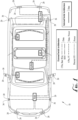
- FIG. 1 shows an overhead view of an outline of an emergency vehicle 10.
- Vehicle 10 is equipped with lightbars and data and power wiring that are the subject of U.S. Patent No. 10,773,634 by Code 3, Inc. of St. Louis, Missouri, which is an affiliate company of Electronic Controls Company (ECCO) of Boise, Idaho, the assignee of this patent application.
- FIG. 1 shows how light modules 20 are mounted about the periphery of vehicle 10.
- the present inventors have recognized that, for some applications, it would be advantageous to employ a unitary type of light module that is mountable atop flat or curved surfaces of vehicle 10 without specialized curved bezels.
- FIG. 1 shows how light module 20 may be deployed as bumper light modules 26 mounted atop flat surfaces, mirror light modules 30 conforming to curved mirror-housing surfaces, and fender light modules 36 conforming to exterior surfaces of fender flares.
- FIGS. 2 and 3 show flexible light module 20, respectively, with and without a removable flat-surface mounting bezel 40 and foam backing pad 44 for accommodating flat-surface mounting locations. Such optional components may be removed for mounting on curved surface, as shown in FIG. 5 .
- FIGS. 4 and 5 provide a comparison in which a prior art light module 48 ( FIG. 4 ) cannot be installed on a mirror housing without an additional bezel or bracket.
- FIG. 5 shows light module 20 is bendable along its longitudinal axis 50 ( FIG. 2 ). Bending is facilitated by flexible components (described later with reference to FIGS. 6 and 7 ) and multiple light segments 54 (e.g., six) defining five flex joints 60 therebetween. Flex joints 60 are oriented such that they are transverse to longitudinal axis 50 to facilitate 30° of bending per side (60° total) from axis 50. Skilled persons will now appreciate, however, that some flex joints orientations and segment locations may be varied to establish different bend radiuses across different axes.
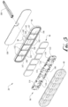
- FIGS. 6 and 7 show in detail components of light module 20.
- modules 20 include a flexible optic 80.
- optic 80 is a clear and flexible rubber, such as silicone, polyurethane, or other types of flexible material.
- a flexible backing 86 is matable with optic 80 to encase electrical components 90 and metal (e.g., aluminum) heatsink segments 94 (also referred to collectively as heatsink 94). Heatsink segments 94 are discrete components, but in other embodiments they are formed a single segmented component (e.g., kerf bendable metal).
- a wiring harness 98 is also molded onto a rear side of backing 86 for receiving wires 100.
- An optional double-sided adhesive panel 108 is also shown.
- Electrical components 90 include circuitry for controlling LEDs. Specifically, a microcontroller 110 ( FIG. 6 ) and associated circuity control optical emission from six pairs of color LEDs 114. Such circuitry is mounted atop a flexible electrical substrate, i.e., circuit board 122.
- flexible circuit board 122 is an aluminum-backed and copper clad printed circuit board (PCB) including pairs of opposing peripheral relief notches 140 ( FIG. 7 ) to facilitate flexing along flex joints.
- backing 86 includes corresponding external notches 142 ( FIG. 6 ) and internal ribs 146 ( FIG. 6 ) that facilitate bending and segmentation of components of heatsink 94. Alignment protrusions 147 on ribs 146 fit in corresponding apertures to aid in alignment of and heat dissipation from board 122.
- each segment of light module 20 includes a discrete PCB, and the discrete PCBs are electrically coupled via wires or flexible flat cables (FFCs).
- FFCs flexible flat cables
- one or more flexible printed circuits (FPC) are employed in lieu of or in addition to FFCs and PCBs. Skilled persons will appreciate that the choice of flexible circuit materials will depend on the size of the light module, the amount of desired bend and bend radius, the heat dissipation properties, and other design parameters.
- an adhesive, ultrasonic weld, or other technique is used to bond each metal segment of heatsink 94 to its corresponding confronting portion of electrical components 90.
- Electrical components 90 and heatsink 94 are assembled into backing 86, then optic 80 is bonded to backing 86 with adhesive to form a weather resistant flexible housing.
- heat is conducted from the LEDs and electronics through PCB surface 148 ( FIG. 7 ), through aluminum heatsink 94, and to backing 86.
- a thermally conductive grease or adhesive is applied between heatsink 90 and backing 86 to further facilitate heat dissipation.
- Optical elements acts upon the light passing through the clear (or colored) flexible optic 80, and may comprise such as a lens, prism, or mirror.
- an optical element provides for total internal reflection (TIR) maximizing light emission from LEDs.
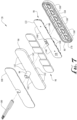
- FIGS. 7 and 8 show in greater detail features of optical elements 160 that direct light from LEDs 114.
- Each pair of LEDs 114 is centrally located in an aperture of a corresponding elliptic cylinder 170 defining an inner surface of an optical element.
- An outer wall 164 (shown in FIGS. 7 and 13 ) defining is generally frustoconical or otherwise tapered toward the LED-receiving aperture to define elliptic cylinder 170. Such taper also facilitates bending by providing spatial displacement between optical elements 160 as they are bent inwards towards each other. Additional details of optic 80 are shown and described later with reference to FIG. 13
- FIG. 8 also shows how each elliptic cylinder 170 is capped by a silicone membrane 180 extending between internal silicon sidewalls 182. Flex joints 60 are formed by depressions in an exterior surface 200 of optic 80 between optical elements 160. Accordingly, each segment 54 ( FIG. 3 ) includes a separate optic, pair of LEDs and associated circuitry, heatsink segment, and at least one flex joint.
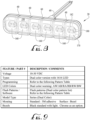
- FIG. 9 provides an overview of various features available in light module 20. For instance, it is compatible with 12- and 24-volt (V) systems, supports various color options described in connection with FIG. 10 , and includes flash patterns that are configurable based on signals applied to wires in accordance with FIGS. 11 and 12 .
- V 12- and 24-volt
- red and amber LEDs on a left-hand side are called, respectively, Color 1 and Color 2.
- red and amber LEDs on a right-hand side are called, respectively, Color 3 and Color 4.
- FIG. 11 is a table describing wiring and electrical control functions for light module 20, according to one embodiment.
- dual positive means positive can be applied to red alone, white alone, or both red and white.
- the sync function uses a signal from the microprocessor so if two lights are connected the timing of the flashes is synchronized. This allows multiple lights on the vehicle to either flash at exactly the same time or exactly opposite from each other if they are set to different phases.
- the term negative is DC ground.
- FIG. 12 shows examples of various standard flash patterns available for light module 20.
- the patterns are established by applying a voltage to one or both "Red” and “White” wires, and by sequentially grounding the "Blue” wire until the desired pattern is set.
- the patterns include options for different flash rates measured in flashes per minute (FPM), different synchronous color combinations (not shown), and different alternately flashing color combinations (not shown). Steady burn (i.e., no appearance of flash) options are also supported.
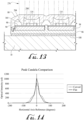
- FIG. 13 shows the directional light output 276 generated by optic 80.
- a peripheral portion of light emitted from LEDs 114 passes through a solid inner wall 280 and reflects from an inside surface 284 of outer wall 164 and outward through optic 80.
- Other light from LEDs 114 passes through the center of optic 80.
- FIG. 14 shows light module 20 emits SAE J845 Class 1 light output across a 60-degree spread when it is mounted flat. At its maximum curvature, light module 20 provides 80° of SAE J845 Class 1 light output. There is some reduction of light output at the center of light module 20 when it is mounted on a curved surface.
Landscapes
- Engineering & Computer Science (AREA)
- General Engineering & Computer Science (AREA)
- Mechanical Engineering (AREA)
- Physics & Mathematics (AREA)
- Microelectronics & Electronic Packaging (AREA)
- Optics & Photonics (AREA)
- Non-Portable Lighting Devices Or Systems Thereof (AREA)
- Led Device Packages (AREA)
- Road Signs Or Road Markings (AREA)
- Audible And Visible Signals (AREA)
- Length Measuring Devices By Optical Means (AREA)
Applications Claiming Priority (3)
| Application Number | Priority Date | Filing Date | Title |
|---|---|---|---|
| US202062959149P | 2020-01-09 | 2020-01-09 | |
| EP21738536.8A EP4088059B1 (de) | 2020-01-09 | 2021-01-08 | Flexibles direktionales fahrzeugwarnlicht |
| PCT/US2021/012815 WO2021142350A1 (en) | 2020-01-09 | 2021-01-08 | Flexible directional vehicle warning light |
Related Parent Applications (1)
| Application Number | Title | Priority Date | Filing Date |
|---|---|---|---|
| EP21738536.8A Division EP4088059B1 (de) | 2020-01-09 | 2021-01-08 | Flexibles direktionales fahrzeugwarnlicht |
Publications (2)
| Publication Number | Publication Date |
|---|---|
| EP4501706A2 true EP4501706A2 (de) | 2025-02-05 |
| EP4501706A3 EP4501706A3 (de) | 2025-06-04 |
Family
ID=76788302
Family Applications (2)
| Application Number | Title | Priority Date | Filing Date |
|---|---|---|---|
| EP24218293.9A Pending EP4501706A3 (de) | 2020-01-09 | 2021-01-08 | Flexible richtungsabhängige warnleuchte für fahrzeuge |
| EP21738536.8A Active EP4088059B1 (de) | 2020-01-09 | 2021-01-08 | Flexibles direktionales fahrzeugwarnlicht |
Family Applications After (1)
| Application Number | Title | Priority Date | Filing Date |
|---|---|---|---|
| EP21738536.8A Active EP4088059B1 (de) | 2020-01-09 | 2021-01-08 | Flexibles direktionales fahrzeugwarnlicht |
Country Status (4)
| Country | Link |
|---|---|
| US (3) | US11841123B2 (de) |
| EP (2) | EP4501706A3 (de) |
| AU (1) | AU2021205517B2 (de) |
| WO (1) | WO2021142350A1 (de) |
Families Citing this family (11)
| Publication number | Priority date | Publication date | Assignee | Title |
|---|---|---|---|---|
| USD1010179S1 (en) | 2020-01-09 | 2024-01-02 | Electronic Controls Company | Flexible directional vehicle warning light |
| EP4501706A3 (de) | 2020-01-09 | 2025-06-04 | Electronic Controls Company | Flexible richtungsabhängige warnleuchte für fahrzeuge |
| EP4265961B1 (de) * | 2022-04-22 | 2025-05-28 | Marelli Automotive Lighting Italy S.p.A. Con Socio Unico | Kfz-beleuchtungseinrichtung und zugehöriges herstellungsverfahren |
| CN115095814A (zh) * | 2022-05-17 | 2022-09-23 | 宁波瓦萨智能科技有限公司 | 一种散热性好的可弯曲警示灯 |
| US12078338B2 (en) * | 2022-07-20 | 2024-09-03 | Emergency Technology, Inc. | Optical element with different transmittances for a lighting assembly |
| US11867376B1 (en) * | 2023-02-16 | 2024-01-09 | Po-Yen Chen | Warning lamp structure |
| TWI885491B (zh) * | 2023-09-18 | 2025-06-01 | 巨輪興業股份有限公司 | 可彎警示排燈 |
| TWI890183B (zh) * | 2023-11-01 | 2025-07-11 | 巨輪興業股份有限公司 | 警示燈結構 |
| US12320493B1 (en) * | 2023-11-17 | 2025-06-03 | Juluen Enterprise Co., Ltd. | Flexible warning light |
| EP4556313A1 (de) * | 2023-11-17 | 2025-05-21 | Juluen Enterprise Co., Ltd. | Flexible warnleuchte |
| DE102024202679B3 (de) * | 2024-03-21 | 2025-08-14 | Moba Mobile Automation Aktiengesellschaft | Signalleuchte |
Citations (1)
| Publication number | Priority date | Publication date | Assignee | Title |
|---|---|---|---|---|
| US10773634B2 (en) | 2017-06-14 | 2020-09-15 | Code 3, Inc. | Nested serial network configuration for array of serially connected light heads |
Family Cites Families (41)
| Publication number | Priority date | Publication date | Assignee | Title |
|---|---|---|---|---|
| FR2697485B1 (fr) | 1992-11-02 | 1995-01-20 | Valeo Vision | Feu de signalisation à éléments lumineux modulaires, pour véhicule automobile. |
| DE19819088B4 (de) * | 1998-04-29 | 2008-06-26 | Leopold Kostal Gmbh & Co. Kg | Flexible Leiterplatte |
| USD415296S (en) | 1998-11-16 | 1999-10-12 | Gavin Dale L | Light bar for truck |
| WO2002041276A2 (en) | 2000-11-15 | 2002-05-23 | Snowy Village, Inc. | Led warning light and communication system |
| US20030147253A1 (en) * | 2002-02-06 | 2003-08-07 | Jack Shy | Curved warning light device for attaching to vehicle |
| US6860620B2 (en) | 2003-05-09 | 2005-03-01 | Agilent Technologies, Inc. | Light unit having light emitting diodes |
| JP2005142060A (ja) * | 2003-11-07 | 2005-06-02 | Ichikoh Ind Ltd | 補助信号灯具 |
| USD526430S1 (en) | 2005-09-09 | 2006-08-08 | Hernandez Rafael E | Front-mounted vehicle brake light |
| DE102006031345A1 (de) | 2006-07-06 | 2008-01-10 | Patent-Treuhand-Gesellschaft für elektrische Glühlampen mbH | Formflexibles Beleuchtungssystem |
| DE102007028097B4 (de) | 2007-06-19 | 2015-02-12 | Automotive Lighting Reutlingen Gmbh | Beleuchtungsanordnung mit Halbleiterlichtquellen auf flexiblen Leiterplatten |
| US20090175047A1 (en) | 2008-01-06 | 2009-07-09 | Keng Lien Industrial Co., Ltd. | Auxiliary luminous trim strip of a car lamp |
| USD576754S1 (en) | 2008-01-10 | 2008-09-09 | Lucidity Enterprise Co., Ltd. | Identification light bar |
| US9111778B2 (en) * | 2009-06-05 | 2015-08-18 | Cree, Inc. | Light emitting diode (LED) devices, systems, and methods |
| AU2012100168B4 (en) | 2009-07-17 | 2012-05-03 | Knog Pty Ltd | Portable light |
| USD653783S1 (en) | 2009-09-30 | 2012-02-07 | Vision Motor Sports | Vehicle lighting system |
| KR20110004594U (ko) * | 2009-11-02 | 2011-05-11 | (주)볼텍스 인터내셔널 | 차량용 섬광 스트로브 경광등 |
| US8198109B2 (en) | 2010-08-27 | 2012-06-12 | Quarkstar Llc | Manufacturing methods for solid state light sheet or strip with LEDs connected in series for general illumination |
| US9410665B2 (en) | 2012-07-16 | 2016-08-09 | The Sloan Company, Inc. | Flexible ribbon LED module |
| USD714480S1 (en) | 2012-12-31 | 2014-09-30 | Calvin Chuen Kam Law | Automobile light bar |
| US9464768B2 (en) * | 2013-03-14 | 2016-10-11 | Code 3, Inc. | Collimating light head including base with projecting dome-like lens |
| US9651206B2 (en) | 2014-03-30 | 2017-05-16 | Khatod Optoelectronics Srl | Optic for a LED chip and related LED lighting device |
| WO2015180978A1 (en) * | 2014-05-30 | 2015-12-03 | Koninklijke Philips N.V. | Leds mounted on curved lead frame |
| WO2015184458A1 (en) | 2014-05-30 | 2015-12-03 | Osram Sylvania Inc. | Integrated light engines including flexible optics and flexible light sources |
| CN104332114B (zh) | 2014-11-04 | 2017-10-31 | 深圳金立翔视效科技有限公司 | 可弯曲led模组、圆形led模组以及波浪形led模组 |
| USD759272S1 (en) | 2014-12-17 | 2016-06-14 | Guangzhou Hanma Electronic Technology Co., Ltd. | Lighting unit for a vehicle |
| US10179536B2 (en) * | 2015-08-28 | 2019-01-15 | Uber Technologies, Inc. | Illumination apparatus |
| WO2017059431A1 (en) | 2015-10-01 | 2017-04-06 | Emergency Technology, Inc. | Supplemental lighting element |
| USD788955S1 (en) | 2015-10-12 | 2017-06-06 | Ningbo Yinzhou Self Photoelectron Technology Co., Ltd. | Lighthead |
| MX394776B (es) * | 2017-02-14 | 2025-03-21 | Emergency Tech Inc | Elemento de alumbrado. |
| US20180202622A1 (en) * | 2017-02-24 | 2018-07-19 | Geoffrey Paul Arce | Flexible light bar assembly |
| US10655799B2 (en) | 2017-08-02 | 2020-05-19 | Auroralight Inc. | Optical device alignment and identification |
| US20190157527A1 (en) | 2017-11-22 | 2019-05-23 | GM Global Technology Operations LLC | Light emitting element package |
| US10883695B2 (en) * | 2018-05-30 | 2021-01-05 | Federal Signal Corporation | Modular flexible light bar |
| WO2020016076A1 (en) * | 2018-07-18 | 2020-01-23 | Lumileds Holding B.V. | Flexible light-emitting diode lighting strip with interposer |
| USD939118S1 (en) | 2019-04-03 | 2021-12-21 | Vision X Asia Co., Ltd. | Lamp for a vehicle |
| CN110578878B (zh) * | 2019-09-20 | 2025-03-07 | 深圳市彬赢光电有限公司 | 带透镜的柔性灯条及其制造方法 |
| USD939119S1 (en) | 2019-09-23 | 2021-12-21 | Vision X Asia Co., Ltd. | Lamp for a vehicle |
| US11820281B2 (en) * | 2019-11-08 | 2023-11-21 | Hiviz Lighting, Inc. | Vehicle modular accessory mounting system |
| EP4501706A3 (de) | 2020-01-09 | 2025-06-04 | Electronic Controls Company | Flexible richtungsabhängige warnleuchte für fahrzeuge |
| USD974605S1 (en) | 2020-10-02 | 2023-01-03 | GM Global Technology Operations LLC | Vehicle front center lamp |
| USD970764S1 (en) | 2021-04-20 | 2022-11-22 | Chongqing Fuwei Auto Parts Co., Ltd | Lens headlamp |
-
2021
- 2021-01-08 EP EP24218293.9A patent/EP4501706A3/de active Pending
- 2021-01-08 US US17/758,537 patent/US11841123B2/en active Active
- 2021-01-08 WO PCT/US2021/012815 patent/WO2021142350A1/en not_active Ceased
- 2021-01-08 AU AU2021205517A patent/AU2021205517B2/en active Active
- 2021-01-08 EP EP21738536.8A patent/EP4088059B1/de active Active
-
2023
- 2023-11-02 US US18/501,025 patent/US12181123B2/en active Active
-
2024
- 2024-11-23 US US18/957,734 patent/US12504142B2/en active Active
Patent Citations (1)
| Publication number | Priority date | Publication date | Assignee | Title |
|---|---|---|---|---|
| US10773634B2 (en) | 2017-06-14 | 2020-09-15 | Code 3, Inc. | Nested serial network configuration for array of serially connected light heads |
Also Published As
| Publication number | Publication date |
|---|---|
| WO2021142350A1 (en) | 2021-07-15 |
| US11841123B2 (en) | 2023-12-12 |
| EP4088059B1 (de) | 2024-12-11 |
| US20240230053A1 (en) | 2024-07-11 |
| US12181123B2 (en) | 2024-12-31 |
| US20250198589A1 (en) | 2025-06-19 |
| EP4501706A3 (de) | 2025-06-04 |
| EP4088059A4 (de) | 2024-02-07 |
| US12504142B2 (en) | 2025-12-23 |
| EP4088059C0 (de) | 2024-12-11 |
| AU2021205517B2 (en) | 2025-01-30 |
| AU2021205517A1 (en) | 2022-08-18 |
| EP4088059A1 (de) | 2022-11-16 |
| US20230036850A1 (en) | 2023-02-02 |
Similar Documents
| Publication | Publication Date | Title |
|---|---|---|
| US11841123B2 (en) | Flexible directional vehicle warning light | |
| US6963438B2 (en) | Rearview mirror constructed for efficient assembly | |
| US10247378B2 (en) | Metal PCB, headlight module having metal PCB applied thereto, and method for assembling headlight module | |
| US20040070857A1 (en) | Rearview mirror assembly construction | |
| WO2007117854A2 (en) | Light bar and method for making | |
| US20090067169A1 (en) | Luminous module and method for producing it | |
| US20090201690A1 (en) | Indicator display assembly for a vehicle rearview mirror | |
| CN106338043A (zh) | 光源单元、照明装置和车辆 | |
| EP1559614B1 (de) | Aussenrückspiegel für Fahrzeuge und Beleuchtungseinrichtung für einen solchen Aussenrückspiegel | |
| EP1712417A1 (de) | Mehrsignalvorrichtung für fahrzeug mit einem lichtabgabekern | |
| JP2002539026A (ja) | 半導体発光エミッタパッケージを使用するインジケータ及び照明器 | |
| US20250024597A1 (en) | Flexible automotive grade light source | |
| CN117677795B (zh) | 具有突出销的散热器及制造方法 | |
| EP1726480A2 (de) | Eine blinklicht emittierende vorrichtung umfassende kraftfahrzeug-rückspiegelanordnung | |
| US11655968B2 (en) | Light-emitting module | |
| US11997373B2 (en) | Camera module for a vehicle | |
| KR20160004498U (ko) | 차량용 램프 | |
| JPH0733295Y2 (ja) | 車輌用灯具 | |
| EP4606642A1 (de) | Multifunktionslichtmodul für einen aussen-rückspiegel eines kfz, aussen-rückspiegelvorrichtung und fahrzeug | |
| WO2025015249A1 (en) | Flexible automotive grade light source | |
| JP2003137028A (ja) | オーバーヘッドコンソールのルーム・マップランプ構造 | |
| JP2002343110A (ja) | 車両のランプ | |
| JP2000222933A (ja) | 照明装置 |
Legal Events
| Date | Code | Title | Description |
|---|---|---|---|
| PUAI | Public reference made under article 153(3) epc to a published international application that has entered the european phase |
Free format text: ORIGINAL CODE: 0009012 |
|
| STAA | Information on the status of an ep patent application or granted ep patent |
Free format text: STATUS: THE APPLICATION HAS BEEN PUBLISHED |
|
| AC | Divisional application: reference to earlier application |
Ref document number: 4088059 Country of ref document: EP Kind code of ref document: P |
|
| AK | Designated contracting states |
Kind code of ref document: A2 Designated state(s): AL AT BE BG CH CY CZ DE DK EE ES FI FR GB GR HR HU IE IS IT LI LT LU LV MC MK MT NL NO PL PT RO RS SE SI SK SM TR |
|
| REG | Reference to a national code |
Ref country code: DE Ref legal event code: R079 Free format text: PREVIOUS MAIN CLASS: B60Q0001260000 Ipc: F21S0004000000 |
|
| PUAL | Search report despatched |
Free format text: ORIGINAL CODE: 0009013 |
|
| AK | Designated contracting states |
Kind code of ref document: A3 Designated state(s): AL AT BE BG CH CY CZ DE DK EE ES FI FR GB GR HR HU IE IS IT LI LT LU LV MC MK MT NL NO PL PT RO RS SE SI SK SM TR |
|
| RIC1 | Information provided on ipc code assigned before grant |
Ipc: F21Y 115/10 20160101ALI20250430BHEP Ipc: B60Q 1/52 20060101ALI20250430BHEP Ipc: B60Q 1/26 20060101ALI20250430BHEP Ipc: F21V 5/04 20060101ALI20250430BHEP Ipc: F21S 4/00 20160101AFI20250430BHEP |
|
| STAA | Information on the status of an ep patent application or granted ep patent |
Free format text: STATUS: REQUEST FOR EXAMINATION WAS MADE |
|
| 17P | Request for examination filed |
Effective date: 20251204 |