EP4501485A1 - Integral forming method for axial special-shaped ring forging - Google Patents
Integral forming method for axial special-shaped ring forging Download PDFInfo
- Publication number
- EP4501485A1 EP4501485A1 EP23887611.4A EP23887611A EP4501485A1 EP 4501485 A1 EP4501485 A1 EP 4501485A1 EP 23887611 A EP23887611 A EP 23887611A EP 4501485 A1 EP4501485 A1 EP 4501485A1
- Authority
- EP
- European Patent Office
- Prior art keywords
- ring
- blank
- rolling
- special
- intermediate rigid
- Prior art date
- Legal status (The legal status is an assumption and is not a legal conclusion. Google has not performed a legal analysis and makes no representation as to the accuracy of the status listed.)
- Pending
Links
Images


Classifications
-
- B—PERFORMING OPERATIONS; TRANSPORTING
- B21—MECHANICAL METAL-WORKING WITHOUT ESSENTIALLY REMOVING MATERIAL; PUNCHING METAL
- B21H—MAKING PARTICULAR METAL OBJECTS BY ROLLING, e.g. SCREWS, WHEELS, RINGS, BARRELS, BALLS
- B21H1/00—Making articles shaped as bodies of revolution
- B21H1/06—Making articles shaped as bodies of revolution rings of restricted axial length
-
- B—PERFORMING OPERATIONS; TRANSPORTING
- B21—MECHANICAL METAL-WORKING WITHOUT ESSENTIALLY REMOVING MATERIAL; PUNCHING METAL
- B21H—MAKING PARTICULAR METAL OBJECTS BY ROLLING, e.g. SCREWS, WHEELS, RINGS, BARRELS, BALLS
- B21H1/00—Making articles shaped as bodies of revolution
- B21H1/22—Making articles shaped as bodies of revolution characterised by use of rolls having circumferentially varying profile ; Die-rolling
-
- B—PERFORMING OPERATIONS; TRANSPORTING
- B21—MECHANICAL METAL-WORKING WITHOUT ESSENTIALLY REMOVING MATERIAL; PUNCHING METAL
- B21H—MAKING PARTICULAR METAL OBJECTS BY ROLLING, e.g. SCREWS, WHEELS, RINGS, BARRELS, BALLS
- B21H5/00—Making gear wheels, racks, spline shafts or worms
- B21H5/02—Making gear wheels, racks, spline shafts or worms with cylindrical outline, e.g. by means of die rolls
-
- B—PERFORMING OPERATIONS; TRANSPORTING
- B21—MECHANICAL METAL-WORKING WITHOUT ESSENTIALLY REMOVING MATERIAL; PUNCHING METAL
- B21J—FORGING; HAMMERING; PRESSING METAL; RIVETING; FORGE FURNACES
- B21J5/00—Methods for forging, hammering, or pressing; Special equipment or accessories therefor
- B21J5/002—Hybrid process, e.g. forging following casting
-
- B—PERFORMING OPERATIONS; TRANSPORTING
- B21—MECHANICAL METAL-WORKING WITHOUT ESSENTIALLY REMOVING MATERIAL; PUNCHING METAL
- B21K—MAKING FORGED OR PRESSED METAL PRODUCTS, e.g. HORSE-SHOES, RIVETS, BOLTS OR WHEELS
- B21K1/00—Making machine elements
- B21K1/76—Making machine elements elements not mentioned in one of the preceding groups
- B21K1/761—Making machine elements elements not mentioned in one of the preceding groups rings
Definitions
- the present invention belongs to the technical field of rolling processes, and in particular to an integral forming method for an axial special-shaped ring forging.
- the existing patent CN102085549B discloses a forming method for machining an outer peripheral surface of a high cylinder forging by using a follow-up mold sleeve.
- a circumferential groove of the inner ring surface of the follow-up mold sleeve is in a circumferential direction, so only the special-shaped rolling in a circumferential direction can be achieved.
- ring rolling is characterized by the continuous deformation of metal in the circumferential direction
- the existing special-shaped ring forgings are all shaped in the circumferential direction, and the special-shaped rings are evenly distributed along the circumference, that is, the shapes of each axial section position must be the same.
- the present invention provides an integral forming method for an axial special-shaped ring forging.
- a near-net forming production and manufacturing of the axial special-shaped ring forging are achieved by introducing intermediate rigid molds with axial grooves.
- the core roller is a straight-wall core roller, or a special-shaped core roller.
- one or both ends of the special-shaped core roller are provided with flange steps for rolling special-shaped ring rolling of the inner hole of the ring blank, and an inner end frame flange is formed in an inner wall surface of the ring blank.
- a procedure for performing special-shaped ring rolling of the inner hole using the special-shaped core roller is between Step S5 of pre-rolling and Step S6 of heating for axially rolling a special-shaped ring, and comprises specific steps as follows: heating the ring blank obtained by pre-rolling in Step S5 to 440-480°C, taking the ring blank out the furnace after heat preservation for 9-12 h, and then performing special-shaped ring rolling of the inner hole of the heated ring blank by using the special-shaped core roller and the straight-wall main roller to obtain a ring blank with a special-shaped inner hole.
- Step S2 includes specific steps as follows: performing upsetting and drawing-out and upsetting in a Z-axis direction, drawing-out and upsetting in a Y-axis direction, and drawing-out and upsetting in an X-axis direction on the blank in turn by using a press, then drawing-out in the Z-axis direction, controlling the deformation amount of each pass to be 45%-55%, and controlling a forging pressing speed of the press to be 10-50 mm/s.
- Step S3 specifically includes the following steps:
- the deformation amount of the pre-rolling is controlled to be 45%-60%
- the rotating speed of the straight-wall main roller is 1.5-1.7 rad/s
- the increase of speed for ring rolling is controlled to be 8-12 mm/s
- the blank is pre-rolled to a ring blank with a rectangular section.
- the deformation amount of special-shaped ring rolling of the inner hole is controlled to be 25%-40%
- the rotating speed of the straight-wall main roller is 1.2-1.5 rad/s
- the increase of speed for ring rolling is controlled to be 5-8 mm/s.
- the intermediate rigid mold is an annular mold, at least one axially arranged axial groove is distributed on an inner wall surface of the ring mold in a circumferential direction, and the axial groove is in fit with an axial stringer of a target ring forging.
- an integral forming method for an axial special-shaped ring forming disclosed by the present invention has the following advantages:
- an axial special-shaped ring forging with an outer axial stringer and upper and lower inner end frame flanges is provided, with specific forming steps as follows:
- a special-shaped ring forging with an axial stringer is provided, with specific forming steps as follows:
- the axial special-shaped forming mechanism of the axial special-shaped ring forging is as follows:
- the arrangement of the axial groove of the intermediate rigid mold can be, but not limited to, the structure of the intermediate rigid mold in the above embodiment, and can be designed according to an outer axial special-shaped structure of the actual axial special-shaped ring forging, which is suitable for the forming of various types ring forgings with outer axial stringers.
- a special-shaped structure of the special-shaped core roller is in fit with a special-shaped structure of the inner hole of the target ring forging.
- the integral forming method for an axial special-shaped ring forging provided by the present invention can be applied to various high-temperature alloy, titanium alloy, aluminum alloy, magnesium alloy, stainless steel, steel, and other ring forgings.
- the axial shape of the excircle may be any continuous or discontinuous shape such as circle, square and triangle, which can be implemented using this method.
Landscapes
- Engineering & Computer Science (AREA)
- Mechanical Engineering (AREA)
- Forging (AREA)
Abstract
Description
- The present invention belongs to the technical field of rolling processes, and in particular to an integral forming method for an axial special-shaped ring forging.
- With the rapid development of aerospace industry, modern national defense industry and transportation industry in China and at abroad, the demand for ring forgings for aerospace vehicles and aero-engines is increasing. As the ring rolling technology becomes more and more mature, the design of ring parts is becoming more and more refined, and the near-net forming design and manufacturing application of special-shaped ring forgings also become more and more extensive. The cross section of the special-shaped ring forging is closer to the shape outline of the parts, which can greatly reduce the machining allowance, thus reducing the damage of machining to the forging streamline of the ring, saving a lot of precious metal materials, and improving the material utilization rate.
- However, at present, there is no manufacturer capable of achieving the integral forming of special-shaped ring forgings with axial stringers in outer diameter in China and at abroad. At present, the main production process of such products is as follows: firstly, the flange with end frame in the inner hole is machined after using straight-wall ring rolling, and then the outer diameter is machined by milling to achieve axial abnormity of the outer diameter. However, in such a production process, the material utilization rate is extremely low, the flow line of forgings is destroyed, the working procedure is complicated, and the comprehensive cost is high.
- In addition, the existing patent
CN102085549B discloses a forming method for machining an outer peripheral surface of a high cylinder forging by using a follow-up mold sleeve. However, in this patent, a circumferential groove of the inner ring surface of the follow-up mold sleeve is in a circumferential direction, so only the special-shaped rolling in a circumferential direction can be achieved. Because ring rolling is characterized by the continuous deformation of metal in the circumferential direction, the existing special-shaped ring forgings are all shaped in the circumferential direction, and the special-shaped rings are evenly distributed along the circumference, that is, the shapes of each axial section position must be the same. With the development of ring rolling equipment, even if this method is not adopted, the production of such ring-shaped special-shaped ring forgings can be achieved. However, there is no report about the integral forming of the axial special-shaped ring forgings in China and at abroad. - For the problems in the prior art, the present invention provides an integral forming method for an axial special-shaped ring forging. A near-net forming production and manufacturing of the axial special-shaped ring forging are achieved by introducing intermediate rigid molds with axial grooves.
- The technical objective of the present invention is achieved through the following technical solutions:
- S1: heating for forging: heating a blank to 440-480°C, and taking the blank out of a furnace after heat preservation for 18-20 h;
- S2: forging in multiple directions: forging the blank in multiple directions by using a press to improve structure properties of the blank, thus obtaining a cylindrical blank;
- S3: punching an upsetting cake: upsetting and deforming the cylindrical blank in an axial direction, and punching the cylindrical blank with a cylindrical punch after reaching a predetermined height to obtain a ring blank with a hole;
- S4: heating for pre-rolling: heating the ring blank with a hole obtained in Step S3 to 440-480°C, taking the ring blank out of the furnace after heat preservation for 9-12 h;
- S5: pre-rolling: pre-rolling the ring blank with a hole, and pre-rolling the blank to a ring blank with a rectangular axial section;
- S6: axially rolling a special-shaped ring: heating the ring blank to 440-480°C, taking the ring blank out of the furnace after heat preservation for 9-12 h, and then placing the ring blank obtained by heating into intermediate rigid molds, wherein the intermediate rigid molds are special-shaped molds provided with axial grooves, the intermediate rigid molds are in cooperation with core rollers and a straight-wall main roller, and final rolling is performed to obtain an axial special-shaped ring forging, wherein a specific cooperative rolling method of the intermediate rigid molds, the core rollers and the straight-wall main roller is as follows:
controlling the straight-wall main roller to rotate in a forward direction; driving, by the straight-wall main roller, the intermediate rigid mold to rotate in a reverse direction; driving, by the intermediate rigid mold, the ring blank to rotate accordingly in the reverse direction, controlling the core roller to make a feed motion towards a direction of the straight-wall main roller in a radial direction, and making a hold roller in contact with an outer diameter of the intermediate rigid mold, wherein when an outer diameter of the ring blank is completely attached to an inner diameter of the intermediate rigid mold, the ring blank and the intermediate rigid mold move synchronously, and have consistent angular velocity and linear velocity; and continuously controlling the straight-wall main roller to rotate in the forward direction, and controlling the core roller to make the feed motion towards a direction of the straight-wall main roller in the radial direction. - Preferably, the core roller is a straight-wall core roller, or a special-shaped core roller.
- Preferably, one or both ends of the special-shaped core roller are provided with flange steps for rolling special-shaped ring rolling of the inner hole of the ring blank, and an inner end frame flange is formed in an inner wall surface of the ring blank.
- Preferably, a procedure for performing special-shaped ring rolling of the inner hole using the special-shaped core roller is between Step S5 of pre-rolling and Step S6 of heating for axially rolling a special-shaped ring, and comprises specific steps as follows:
heating the ring blank obtained by pre-rolling in Step S5 to 440-480°C, taking the ring blank out the furnace after heat preservation for 9-12 h, and then performing special-shaped ring rolling of the inner hole of the heated ring blank by using the special-shaped core roller and the straight-wall main roller to obtain a ring blank with a special-shaped inner hole. - Preferably, Step S2 includes specific steps as follows: performing upsetting and drawing-out and upsetting in a Z-axis direction, drawing-out and upsetting in a Y-axis direction, and drawing-out and upsetting in an X-axis direction on the blank in turn by using a press, then drawing-out in the Z-axis direction, controlling the deformation amount of each pass to be 45%-55%, and controlling a forging pressing speed of the press to be 10-50 mm/s.
- Preferably, Step S3 specifically includes the following steps:
- S3-1: performing upsetting and rounding on the cylindrical blank in the Z-axis direction, and controlling the deformation amount to be 45-55%; and
- S3-2: punching the upset blank to a ring blank with a preset size.
- Preferably, in S5, the deformation amount of the pre-rolling is controlled to be 45%-60%, the rotating speed of the straight-wall main roller is 1.5-1.7 rad/s, the increase of speed for ring rolling is controlled to be 8-12 mm/s, and the blank is pre-rolled to a ring blank with a rectangular section.
- Preferably, the deformation amount of special-shaped ring rolling of the inner hole is controlled to be 25%-40%, the rotating speed of the straight-wall main roller is 1.2-1.5 rad/s, and the increase of speed for ring rolling is controlled to be 5-8 mm/s.
- Preferably, in S6, the intermediate rigid mold is an annular mold, at least one axially arranged axial groove is distributed on an inner wall surface of the ring mold in a circumferential direction, and the axial groove is in fit with an axial stringer of a target ring forging.
- Preferably, in S6, specific ring rolling steps are as follows:
- S6-1: preheating the intermediate rigid mold to 350-400°C, and placing the intermediate rigid mold on a working plane of a ring rolling machine;
- S6-2: placing the heated ring blank into the intermediate rigid mold, wherein the outer diameter of the ring blank is less than an inner diameter of the intermediate rigid mold at a moment;
- S6-3: enabling the core roller to penetrate through an inner hole of the ring blank, taking the intermediate rigid mold and the ring blank as a whole, and performing rolling by the ring rolling machine;
- S6-4: controlling the straight-wall main roller to rotate in a forward direction; driving, by the straight-wall main roller, the intermediate rigid mold to rotate in a reverse direction; driving, by the intermediate rigid mold, the ring blank to rotate accordingly in the reverse direction, controlling the core roller to make the feed motion towards a direction of the straight-wall main roller in the radial direction, and making a hold roller in contact with the outer diameter of the intermediate rigid mold, wherein an outer diameter of the ring blank is attached to an inner hole of the intermediate rigid mold after deformation amount of the ring blank reaches 5-8%, a rotating speed of the straight-wall main roller is 1.2-1.5 rad/s, the increase of speed for ring rolling is 2-5 mm/s, and a feed speed of the core roller is 0.5-0.8 mm/s; and
- S6-5: when the outer diameter of the ring blank is completely attached to the inner diameter of the intermediate rigid mold, moving the ring blank and the intermediate rigid synchronously, and making the ring blank and the intermediate rigid have consistent angular velocity and linear velocity; continuously controlling the straight-wall main roller to rotate in the forward direction, enabling the core roller to make the feed motion towards the direction of the straight-wall main roller in the radial direction, wherein the rotating speed of the straight-wall main roller is 0.8-1.2 rad/s, the increase of speed for ring rolling is 0.5-1 mm/s, and the feed speed of the core roller is 0.3-0.6 mm/s.
- The beneficial effects are as follows: an integral forming method for an axial special-shaped ring forming disclosed by the present invention has the following advantages:
- (1) By introducing the intermediate rigid mold, the near-net forming production and manufacturing of the axial special-shaped ring forging are achieved, a machining allowance is reduced, the utilization rate of the raw materials is improved, and the retained forging streamline reduces the raw material cost and machining cost.
- (2) The axial special-shaped ring forgings manufactured by the method provided by the present invention can achieve uneven distribution of abnormal sections in the circumferential direction, and the shapes of various axial section positions may be inconsistent, and are suitable for forming various types of axial special-shaped ring forgings.
-
-
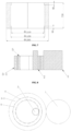
FIG. 1 is a first schematic structural diagram of a target ring forging according toEmbodiment 1; -
FIG. 2 is a second schematic structural diagram of a target ring forging according toEmbodiment 1; -
FIG. 3 is a three-dimensional diagram of a target ring forging according toEmbodiment 1; -
FIG. 4 is a first schematic diagram of special-shaped ring rolling of an inner hole inStep 6 according toEmbodiment 1; -
FIG. 5 is a second schematic diagram of special-shaped ring rolling of an inner hole inStep 6 according toEmbodiment 1; -
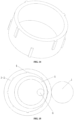
FIG. 6 is a first schematic diagram of a ring blank with a special-shaped inner hole inStep 6 according toEmbodiment 1; -
FIG. 7 is a second schematic diagram of a ring blank with a special-shaped inner hole inStep 6 according toEmbodiment 1; -
FIG. 8 is a first schematic diagram of rolling of a ring blank in Step 7-4 according toEmbodiment 1; -
FIG. 9 is a second schematic diagram of rolling of a ring blank in Step 7-4 according toEmbodiment 1; -
FIG. 10 is a first schematic diagram of rolling of a ring blank in Step 7-5 according toEmbodiment 1; -
FIG. 11 is a second schematic diagram of rolling of a ring blank in Step 7-5 according toEmbodiment 1; -
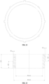
FIG. 12 is a first schematic structural diagram of a target ring forging according toEmbodiment 2; -
FIG. 13 is a second schematic structural diagram of a target ring forging according toEmbodiment 2; -
FIG. 14 is a three-dimensional diagram of a target ring forging according toEmbodiment 2; -
FIG. 15 is a first schematic diagram of rolling of a ring blank inStep 6 according toEmbodiment 2; -
FIG. 16 is a second schematic diagram of rolling of a ring blank inStep 6 according toEmbodiment 2; -
FIG. 17 is a first schematic diagram of rolling of a ring blank in Step 6-5 according toEmbodiment 2; -
FIG. 18 is a second schematic diagram of rolling of a ring blank in Step 6-5 according toEmbodiment 2. - In the drawings: 1-straight-wall main roller; 2-special-shaped core roller; 2-1-flange step; 3-1-intermediate rigid mold I; 3-2-intermediate rigid mold II; 4-axial groove; 5-ring blank; 6-straight-wall core roller.
- To make the objectives, technical solutions and advantages of the present invention more clearly and apparently, the present invention is further described in detail below in conjunction with the accompanying drawings and embodiments. It should be understood that the specific embodiments described here are only used to explain the present invention than limiting.
- As shown in
FIG. 1 to FIG. 3 , an axial special-shaped ring forging with an outer axial stringer and upper and lower inner end frame flanges is provided, with specific forming steps as follows: -
Step 1. Heating for forging: 660 kg aluminum alloy bars (Φ500×1200) ≤400°C are placed into a furnace, and then taken out the furnace after the temperature is increased to 460°C and kept at 460°C for 18 h. -
Step 2. Forging in multiple directions: the blank is forged in multiple directions by using a press to improve the structure property of the blank, thus obtaining a cylindrical blank. The specific steps are as follows:
in a Z-axis direction of the blank (the aluminum alloy bar), the blank is upset to 620×620×610 (the deformation amount in the Z-axis direction is 49.2%), drawn out to 420×420×1350 (the deformation amount in the Z-axis direction is 54.8%), and upset to 620×620×610 (the deformation amount in the Z-axis direction is 54.8%). Afterwards, in a Y-axis direction of the blank, the blank is drawn out to 420×1350×420 (the deformation amount in the Y-axis direction is 54.1%), and upset to 620×610×620 (the deformation amount in the Y-axis direction is 54.8%). Then, in an X-axis direction of the blank, the blank is drawn out to 1350×420×420 (the deformation amount in the X-axis direction is 54.1%), and upset to 610×620×620 (the deformation amount in the X-axis direction is 54.8%). Finally, in the Z-axis direction, the blank is drawn out to 420×420×1350 (the deformation amount in the Z-axis direction is 54.1%). In this embodiment, the forging pressing speed of the press is controlled to be 30 mm/s. In the present invention, the size in all embodiments is mm in unit. - Step 3. Punching an upsetting cake: the upsetting and rounding are performed in the Z-axis direction of the cylindrical blank until the size reaches Φ640×730 (the deformation amount in the Z-axis direction is 45.9%). Afterwards, the cylindrical blank is punched using a cylindrical punch (in which the size of the inner hole is Φ250) to obtain a ring blank with a hole, which has the size of Φ665 (outer diameter) ×Φ250 (inner diameter) ×730.
- Step 4. Heating for pre-rolling: the ring blank with a hole is heated to 460°C and then is taken out of the furnace after the temperature is kept at 460°C for 11 h.
-
Step 5. Pre-rolling: the ring blank with a hole is pre-rolled on a horizontal ring rolling machine to a ring blank 5 with a rectangular axial section until the size is Φ1010 (outer diameter) ×Φ800 (inner diameter) ×730 (the deformation amount of wall thickness is 49.3%). The rotating speed of the straight-wallmain roller 1 is controlled to be 1.5 rad/s, and the increase of the speed for ring rolling is 10 mm/s. - S6. Special-shaped ring rolling of an inner hole: after the
ring blank 5 is heated to 460°C, and then is taken out of the furnace after the temperature is kept at 460°C for 11 h. As shown nFIG. 4 andFIG. 5 , a special-shapedcore roller 2 and a straight-wallmain roller 1 are used to perform special-shaped ring rolling of an inner hole of the heated ring blank 5, thus obtaining the ring blank 5 (with the deformation amount of 28.6%) with upper and lower inner end frame flanges shown inFIG. 6 andFIG. 7 . InEmbodiment 1, both ends of the special-shapedcore roller 2 shown inFIG. 4 are provided with flange steps 2-1. A roller surface of the special-shapedcore roller 2 is attached to a wall surface of the inner hole of thering blank 5, the straight-wallmain roller 1 is attached to an outer wall surface of thering blank 5, the rotating speed of the straight-wallmain roller 1 is controlled to be 1.4 rad/s, and the increase of speed for ring rolling is 6 mm/s. - Step 7. Axially rolling a special-shaped ring: the
ring blank 5 is heated to 460°C, then is taken out of the furnace after the temperature is kept at 460°C for 10 h. Thering blank 5 is placed in the intermediate rigid mold I 3-1, and the intermediate rigid mold I 3-1 is in cooperation with the special-shapedcore roller 2 and the straight-wallmain roller 1 for final rolling, thus obtaining a special-shaped ring forging with an outer axial stringer and an inner end frame flange shown inFIG. 1 to FIG. 3 . The final rolling inEmbodiment 1 includes the specific steps as follows:- Step 7-1. The intermediate rigid mold I 3-1 is preheated to 350°C, and then placed on a working plane of a ring rolling machine.
- Step 7-2. The heated ring blank 5 is placed in the intermediate rigid mold I 3-1, at this time, an outer diameter of the
ring blank 5 is less than an inner diameter of the intermediate rigid mold I 3-1. - Step 7-3. The special-shaped
core roller 2 penetrates through an inner hole of thering blank 5, and the intermediate rigid mold I 3-1 and thering blank 5 are used as an integer for rolling by the ring rolling machine. - Step 7-4. The straight-wall
main roller 1 is controlled to rotate counterclockwise (in this embodiment, the counterclockwise rotation is forward rotation), the intermediate rigid mold I 3-1 is driven by the straight-wallmain roller 1 to rotate clockwise, and thering blank 5 is driven by the intermediate rigid mold I 3-1 to rotate clockwise accordingly. Meanwhile, the special-shapedcore roller 2 is controlled to make a feed motion towards a direction of the straight-wallmain roller 1 in a radial direction, making a hold roller in contact with the outer diameter of the intermediate rigid mold I 3-1. After the deformation amount of thering blank 5 reaches 6.0%, as shown inFIG. 8 andFIG. 9 , the outer diameter of thering blank 5 is attached to the inner hole of the intermediate rigid mold I 3-1. The rotating speed of the straight-wallmain roller 1 is 1.3 rad/s, the increase of speed for ring rolling is 3 mm/s, and the feed speed of the special-shapedcore roller 2 is 0.8 mm/s. - Step 7-5. When the outer diameter of the
ring blank 5 is completely attached to the inner diameter of the intermediate rigid mold I 3-1, thering blank 5 and the intermediate rigid mold I 3-1 move synchronously, and have the consistent angular velocity and linear velocity. As shown inFIG. 10 and FIG. 11 , the straight-wallmain roller 1 is continuously controlled to rotate counterclockwise, and the special-shapedcore roller 2 makes the feed motion towards a direction of the straight-wallmain roller 1 in the radial direction, thus forming an outer axial stringer in an axial groove 4 of the intermediate rigid mold I 3-1, and finally obtaining a target ring forging shown inFIG. 1 to FIG. 3 . The rotating speed of the straight-wallmain roller 1 is 1 rad/s, the increase of speed for ring rolling is 0.6 mm/s, and the feed speed of the special-shapedcore roller 2 is 0.4 mm/s.
- The special-shaped ring forging with an outer axial stringer and upper and lower inner end frame flanges manufactured in
Embodiment 1 is taken, three parallel samples are randomly selected in a chord direction of the forging to test the performance of the forging. Testing results are as follows:Table 1 Performance test results of ring forgings in Embodiment 1 Rm (MPa) Rp0.2 (MPa) A (%) Hardness (HB) Technical requirements ≥420 ≥350 4.5-16 ≥120 1 483 402 14.52 151 2 480 399 15.40 152 3 495 416 14.20 151 - As shown in
FIG. 12 to FIG. 14 , a special-shaped ring forging with an axial stringer is provided, with specific forming steps as follows: -
Step 1. Heating for forging: 1520 kg aluminum alloy bars (Φ650×1635) ≤400°C are placed into a furnace, and then taken out the furnace after the temperature is increased to 460°C and kept at 460°C for 18 h. -
Step 2. Forging in multiple directions: the blank 5 is forged in multiple directions using a press to improve the structure property of the blank and obtain a cylindrical blank. The specific steps are as follows:
in a Z-axis direction of the blank (the aluminum alloy bar), the blank is upset to 825×825×800 (the deformation amount in the Z-axis direction is 51.1%), drawn out to 580×580×1600 (the deformation amount in the Z-axis direction is 50%), and upset to 825×825×800 (the deformation amount in the Z-axis direction is 50%). Afterwards, in a Y-axis direction of the blank, the blank is drawn out to 580×1600×580 (the deformation amount in the Y-axis direction is 48.4%), and upset to 825×800×825 (the deformation amount in the Y-axis direction is 50%). Then, in an X-axis direction of the blank, the blank is drawn out to 1600×580×580 (the deformation amount in the X-axis direction is 48.4%), and upset to 800×825×825 (the deformation amount in the X-axis direction is 50%). Finally, in the Z-axis direction, the blank is drawn out to 580×580×1600 (the deformation amount in the Z-axis direction is 48.4%). In this embodiment, the forging pressing speed of the press is controlled to be 30 mm/s. In the present invention, the size in all embodiments is mm in unit. - Step 3. Punching an upsetting cake: the upsetting and rounding are performed in the Z-axis direction of the cylindrical blank until the size reaches Φ930×800 (the deformation amount in the Z-axis direction is 50%). Afterwards, the cylindrical blank is punched using a cylindrical punch (in which the size of the inner hole is Φ300) to obtain a ring blank with a hole, which has the size of Φ955 (outer diameter) ×Φ300 (inner diameter) ×800.
- Step 4. Heating for pre-rolling: the ring blank with a hole is heated to 460°C and then is taken out of the furnace after the temperature is kept at 460°C for 11 h.
-
Step 5. Pre-rolling: the ring blank with a hole is pre-rolled on a horizontal ring rolling machine to a ring blank 5 with a rectangular axial section until the size is Φ1350 (outer diameter) ×Φ1000 (inner diameter) ×800 (the deformation amount of wall thickness is 46.6%). The rotating speed of the straight-wallmain roller 1 is controlled to be 1.6 rad/s, and the increase of the speed for ring rolling is 12 mm/s. - S6. Rolling a special-shaped ring on an inner hole: after the
ring blank 5 is heated to 450°C, then is taken out of the furnace after the temperature is kept at 450°C for 11 h. Thering blank 5 is placed in an intermediate rigid mold II 3-2 shown inFIG. 15 andFIG. 16 , and the intermediate rigid mold II 3-2 is in cooperation with the straight-wall core roller 6 and the straight-wallmain roller 1 for final rolling, thus obtaining a special-shaped ring forging with an outer axial stringer shown inFIG. 12 to FIG. 14 . The final rolling inEmbodiment 1 includes the specific steps as follows:- Step 6-1. The intermediate rigid mold II 3-2 is preheated to 350°C, and then placed on a working plane of a ring rolling machine.
- Step 6-2. The heated ring blank 5 is placed in the intermediate rigid mold II 3-2, at this time, an outer diameter of the
ring blank 5 is less than an inner diameter of the intermediate rigid mold II 3-2, as shown inFIG. 15 to FIG. 16 . - Step 6-3. The straight-
wall core roller 6 penetrates through the inner hole of thering blank 5, and the intermediate rigid mold II 3-2 and thering blank 5 are used as an integer for rolling by the ring rolling machine. - Step 6-4. The straight-wall
main roller 1 is controlled to rotate counterclockwise (in this embodiment, the counterclockwise rotation is forward rotation), the intermediate rigid mold II 3-2 is driven by the straight-wallmain roller 1 to rotate clockwise, and thering blank 5 is driven by the intermediate rigid mold II 3-2 to rotate clockwise accordingly. Meanwhile, the straight-wall core roller 6 is controlled to make a feed motion towards a direction of the straight-wallmain roller 1 in a radial direction, making a hold roller in contact with the outer diameter of the intermediate rigid mold II 3-2. After the deformation amount of thering blank 5 reaches 5.7%, the outer diameter of thering blank 5 is attached to the inner hole of the intermediate rigid mold II 3-2. The rotating speed of the straight-wallmain roller 1 is 1.2 rad/s, the increase of speed for ring rolling is 2.5 mm/s, and the feed speed of the straight-wall core roller 6 is 0.5 mm/s. - Step 6-5. When the outer diameter of the
ring blank 5 is completely attached to the inner diameter of the intermediate rigid mold II 3-2, as shown inFIG. 17 andFIG. 18 , thering blank 5 and the intermediate rigid mold II 3-2 move synchronously, and have the consistent angular velocity and linear velocity. The straight-wallmain roller 1 is continuously controlled to rotate counterclockwise, and the straight-wall core roller 6 makes the feed motion towards a direction of the straight-wallmain roller 1 in the radial direction, thus forming an outer axial stringer in an axial groove 4 of the intermediate rigid mold II 3-2, and finally obtaining a target ring forging shown inFIG. 12 to FIG. 14 . The rotating speed of the straight-wallmain roller 1 is controlled to be 0.9 rad/s, the increase of speed for ring rolling is 0.8 mm/s, and the feeding speed of the straight-wall core roller 6 is 0.3 mm/s.
- The special-shaped ring forging with an outer axial stringer manufactured in
Embodiment 2 is taken, three parallel samples are randomly selected in a chord direction of the forging to test the performance of the forging. Testing results are as follows:Table 2 Performance test results of ring forgings in Embodiment 2 Rm (MPa) Rp0.2 (MPa) A (%) Hardness (HB) Technical requirements ≥420 ≥350 4.5-16 ≥120 1 491 403 12.76 154 2 486 398 14.04 155 3 488 399 13.64 155 - In the present invention, the axial special-shaped forming mechanism of the axial special-shaped ring forging is as follows:
- (1) The intermediate rigid mold is in cooperation with the core roller and the straight-wall main roller to roll the ring blank, such that the outer diameter of the ring blank can be attached to the intermediate rigid mold.
- (2) The straight-wall main roller is continuously controlled to rotate, and the feed speed of the core roller is reduced for continuous rolling. In this case, due to the constraint of the intermediate rigid mold, the outer diameter of the special-shaped ring forging no longer increases, the inner diameter of the special-shaped ring forging gradually increases, and the wall thickness decreases. According to the principle of constant volume, the outer diameter material of the ring blank will be gradually filled into the axial groove of the intermediate rigid mold, and then the outer axial stringer can be formed in an excircle of the ring blank.
- According to the present invention, the arrangement of the axial groove of the intermediate rigid mold can be, but not limited to, the structure of the intermediate rigid mold in the above embodiment, and can be designed according to an outer axial special-shaped structure of the actual axial special-shaped ring forging, which is suitable for the forming of various types ring forgings with outer axial stringers.
- In the present invention, a special-shaped structure of the special-shaped core roller is in fit with a special-shaped structure of the inner hole of the target ring forging.
- The integral forming method for an axial special-shaped ring forging provided by the present invention can be applied to various high-temperature alloy, titanium alloy, aluminum alloy, magnesium alloy, stainless steel, steel, and other ring forgings. Meanwhile, the axial shape of the excircle may be any continuous or discontinuous shape such as circle, square and triangle, which can be implemented using this method.
- This specific embodiment is not only an explanation of the present invention, and is not intended to limit the present invention. Those skilled in the art can make modifications that do not contribute to the present embodiment as needed after reading the present specification, but as long as the present invention is in the right of the present invention, all requirements are protected by the patent law.
Claims (9)
- An integral forming method for an axial special-shaped ring forging, comprising the following steps:S1: heating for forging: heating a blank to 440-480°C, and taking the blank out of a furnace after heat preservation for 18-20 h;S2: forging in multiple directions: forging the blank in multiple directions by using a press to improve structure properties of the blank, thus obtaining a cylindrical blank;S3: punching an upsetting cake: upsetting and deforming the cylindrical blank in an axial direction, and punching the cylindrical blank with a cylindrical punch after reaching a predetermined height to obtain a ring blank with a hole;S4: heating for pre-rolling: heating the ring blank with a hole obtained in Step S3 to 440-480°C, taking the ring blank out of the furnace after heat preservation for 9-12 h;S5: pre-rolling: pre-rolling the ring blank with a hole, and pre-rolling the blank to a ring blank with a rectangular axial section;S6: axially rolling a special-shaped ring: heating the ring blank to 440-480°C, taking the ring blank out of the furnace after heat preservation for 9-12 h, and then placing the ring blank obtained by heating into intermediate rigid molds, wherein the intermediate rigid molds are special-shaped molds provided with axial grooves, the intermediate rigid molds are in cooperation with core rollers and a straight-wall main roller, and final rolling is performed to obtain an axial special-shaped ring forging, wherein a specific cooperative rolling method of the intermediate rigid molds, the core rollers and the straight-wall main roller is as follows:controlling the straight-wall main roller to rotate in a forward direction; driving, by the straight-wall main roller, the intermediate rigid mold to rotate in a reverse direction; driving, by the intermediate rigid mold, the ring blank to rotate accordingly in the reverse direction, controlling the core roller to make a feed motion towards a direction of the straight-wall main roller in a radial direction, and making a hold roller in contact with an outer diameter of the intermediate rigid mold, wherein when an outer diameter of the ring blank is completely attached to an inner diameter of the intermediate rigid mold, the ring blank and the intermediate rigid mold move synchronously, and have consistent angular velocity and linear velocity; and continuously controlling the straight-wall main roller to rotate in the forward direction, and controlling the core roller to make the feed motion towards a direction of the straight-wall main roller in the radial direction;a specific ring rolling step is as follows:S6-1: preheating the intermediate rigid mold to 350-400°C, and placing the intermediate rigid mold on a working plane of a ring rolling machine;S6-2: placing the heated ring blank into the intermediate rigid mold, wherein the outer diameter of the ring blank is less than an inner diameter of the intermediate rigid mold at the moment;S6-3: enabling the core roller to penetrate through an inner hole of the ring blank, taking the intermediate rigid mold and the ring blank as a whole, and performing rolling by the ring rolling machine;S6-4: controlling the straight-wall main roller to rotate in a forward direction; driving, by the straight-wall main roller, the intermediate rigid mold to rotate in a reverse direction; driving, by the intermediate rigid mold, the ring blank to rotate accordingly in the reverse direction, controlling the core roller to make the feed motion towards a direction of the straight-wall main roller in the radial direction, and making a hold roller in contact with the outer diameter of the intermediate rigid mold, wherein an outer diameter of the ring blank is attached to an inner hole of the intermediate rigid mold after deformation amount of the ring blank reaches 5-8%, a rotating speed of the straight-wall main roller is 1.2-1.5 rad/s, the increase of speed for ring rolling is 2-5 mm/s, and a feed speed of the core roller is 0.5-0.8 mm/s; andS6-5: when the outer diameter of the ring blank is completely attached to the inner diameter of the intermediate rigid mold, moving the ring blank and the intermediate rigid synchronously, and making the ring blank and the intermediate rigid have consistent angular velocity and linear velocity; continuously controlling the straight-wall main roller to rotate in the forward direction, enabling the core roller to make the feed motion towards the direction of the straight-wall main roller in the radial direction, wherein the rotating speed of the straight-wall main roller is 0.8-1.2 rad/s, the increase of speed for ring rolling is 0.5-1 mm/s, and the feed speed of the core roller is 0.3-0.6 mm/s.
- The integral forming method for an axial special-shaped ring forging according to claim 1, wherein the core roller is a straight-wall core roller, or a special-shaped core roller.
- The integral forming method for an axial special-shaped ring forging according to claim 2, wherein one or both ends of the special-shaped core roller are provided with flange steps for rolling special-shaped ring rolling of the inner hole of the ring blank, and an inner end frame flange is formed in an inner wall surface of the ring blank.
- The integral forming method for an axial special-shaped ring forging according to any one of claims 2 to 3, wherein a procedure for performing special-shaped ring rolling of the inner hole using the special-shaped core roller is between Step S5 of pre-rolling and Step S6 of heating for axially rolling a special-shaped ring, and comprises specific steps as follows:
heating the ring blank obtained by pre-rolling in Step S5 to 440-480°C, taking the ring blank out the furnace after heat preservation for 9-12 h, and then performing special-shaped ring rolling of the inner hole of the heated ring blank by using the special-shaped core roller and the straight-wall main roller to obtain a ring blank with a special-shaped inner hole. - The integral forming method for an axial special-shaped ring forging according to claim 1, wherein Step S2 comprises specific steps as follows: performing upsetting and drawing-out and upsetting in a Z-axis direction, drawing-out and upsetting in a Y-axis direction, and drawing-out and upsetting in an X-axis direction on the blank in turn by using a press, then drawing-out in the Z-axis direction, controlling the deformation amount of each pass to be 45%-55%, and controlling a forging pressing speed of the press to be 10-50 mm/s.
- The integral forming method for an axial special-shaped ring forging according to claim 1, wherein Step S3 comprises specific steps as follows:S3-1: performing upsetting and rounding on the cylindrical blank in the Z-axis direction, and controlling the deformation amount to be 45-55%; andS3-2: punching the upset blank to a ring blank with a preset size.
- The integral forming method for an axial special-shaped ring forging according to claim 1, wherein in S5, the deformation amount of the pre-rolling is controlled to be 45%-60%, the rotating speed of the straight-wall main roller is 1.5-1.7 rad/s, the increase of speed for ring rolling is controlled to be 8-12 mm/s, and the blank is pre-rolled to a ring blank with a rectangular section.
- The integral forming method for an axial special-shaped ring forging according to claim 4, wherein the deformation amount of special-shaped ring rolling of the inner hole is controlled to be 25%-40%, the rotating speed of the straight-wall main roller is 1.2-1.5 rad/s, and the increase of speed for ring rolling is controlled to be 5-8 mm/s.
- The integral forming method for an axial special-shaped ring forging according to claim 1, wherein in S6, the intermediate rigid mold is a ring mold, at least one axially arranged axial groove is distributed on an inner wall surface of the ring mold in a circumferential direction, and the axial groove is in fit with an axial stringer of a target ring forging.
Applications Claiming Priority (2)
| Application Number | Priority Date | Filing Date | Title |
|---|---|---|---|
| CN202211398745.9A CN115430801B (en) | 2022-11-09 | 2022-11-09 | Integral forming method for axial special-shaped ring forging |
| PCT/CN2023/116748 WO2024098917A1 (en) | 2022-11-09 | 2023-09-04 | Integral forming method for axial special-shaped ring forging |
Publications (2)
| Publication Number | Publication Date |
|---|---|
| EP4501485A1 true EP4501485A1 (en) | 2025-02-05 |
| EP4501485A4 EP4501485A4 (en) | 2025-10-22 |
Family
ID=84252845
Family Applications (1)
| Application Number | Title | Priority Date | Filing Date |
|---|---|---|---|
| EP23887611.4A Pending EP4501485A4 (en) | 2022-11-09 | 2023-09-04 | INTEGRAL FORMING PROCESS FOR AXIAL SPECIAL-SHAPED RING FORGING |
Country Status (3)
| Country | Link |
|---|---|
| EP (1) | EP4501485A4 (en) |
| CN (1) | CN115430801B (en) |
| WO (1) | WO2024098917A1 (en) |
Families Citing this family (3)
| Publication number | Priority date | Publication date | Assignee | Title |
|---|---|---|---|---|
| CN115430801B (en) * | 2022-11-09 | 2023-02-10 | 无锡派克新材料科技股份有限公司 | Integral forming method for axial special-shaped ring forging |
| CN119187412A (en) * | 2024-09-19 | 2024-12-27 | 洛阳船舶材料研究所(中国船舶集团有限公司第七二五研究所) | Processing deformation control method for TA31 alloy special-shaped cylinder |
| CN119819870B (en) * | 2025-01-08 | 2025-10-10 | 武汉理工大学 | A method for rolling a tapered roller bearing with a complete conformal streamline raceway |
Family Cites Families (14)
| Publication number | Priority date | Publication date | Assignee | Title |
|---|---|---|---|---|
| JPS4826665A (en) * | 1971-08-12 | 1973-04-07 | ||
| JPS61202742A (en) * | 1985-03-07 | 1986-09-08 | Toyota Central Res & Dev Lab Inc | Mold structure for plastic processing |
| JPS6440128A (en) * | 1987-08-04 | 1989-02-10 | Mitsubishi Metal Corp | Manufacture of ring article having protrusion on peripheral part by plastic working |
| JP2643505B2 (en) * | 1989-12-26 | 1997-08-20 | 三菱マテリアル株式会社 | Ring rolling mill |
| WO1992013659A1 (en) * | 1991-02-01 | 1992-08-20 | Ladish Company, Inc. | Integrally stiffened rings |
| CN102085548B (en) * | 2010-12-10 | 2012-08-08 | 贵州安大航空锻造有限责任公司 | Roll forming method of titanium alloy high cylindrical ring forging |
| CN102085549B (en) * | 2010-12-10 | 2012-09-19 | 贵州安大航空锻造有限责任公司 | Rolling Forming Method of Aluminum Alloy High Tube Ring Forgings |
| CN102430897A (en) * | 2011-10-28 | 2012-05-02 | 江阴市恒润环锻有限公司 | Thermal deformation process of flange with special-shaped section |
| CN109351896B (en) * | 2018-11-14 | 2020-12-04 | 湖北汽车工业学院 | A kind of rolling method of super-large diameter 6061 aluminum alloy special-shaped section ring |
| CN210475363U (en) * | 2019-08-27 | 2020-05-08 | 张家港市亨通环形锻件制造有限公司 | Die for internal T-shaped gear forging |
| CN210450757U (en) * | 2019-08-27 | 2020-05-05 | 张家港市亨通环形锻件制造有限公司 | Die for manufacturing inner arc-shaped forge piece |
| CN214108649U (en) * | 2020-11-17 | 2021-09-03 | 重庆骄航科技有限公司 | A device for forming a ring |
| CN113579130B (en) * | 2021-07-29 | 2022-07-22 | 武汉理工大学 | Rolling method for special-shaped thin-wall casing ring forging with external island bosses |
| CN115430801B (en) * | 2022-11-09 | 2023-02-10 | 无锡派克新材料科技股份有限公司 | Integral forming method for axial special-shaped ring forging |
-
2022
- 2022-11-09 CN CN202211398745.9A patent/CN115430801B/en active Active
-
2023
- 2023-09-04 WO PCT/CN2023/116748 patent/WO2024098917A1/en not_active Ceased
- 2023-09-04 EP EP23887611.4A patent/EP4501485A4/en active Pending
Also Published As
| Publication number | Publication date |
|---|---|
| CN115430801A (en) | 2022-12-06 |
| CN115430801B (en) | 2023-02-10 |
| WO2024098917A1 (en) | 2024-05-16 |
| EP4501485A4 (en) | 2025-10-22 |
Similar Documents
| Publication | Publication Date | Title |
|---|---|---|
| EP4501485A1 (en) | Integral forming method for axial special-shaped ring forging | |
| CN106363352B (en) | A kind of manufacturing process of high-strength aluminum alloy ring forging | |
| CN102125972B (en) | Method for rolling and shaping structural steel high cylindrical ring forged piece | |
| CN109773094B (en) | Production process of large-tonnage super-large-diameter aluminum alloy special-shaped ring forging | |
| CN104259762A (en) | Forging and forming method for F22 flange ring pieces with non-uniform sections | |
| CN102615224A (en) | Radial-axial rolling forming method for inner step section ring pieces | |
| CN108890218A (en) | A kind of high strength heat resistant alloy forge piece manufacturing process | |
| CN111531101A (en) | Forging method for outer ring or inner ring of double-row conical bearing | |
| CN109794732B (en) | Rolling-spinning composite precision forming method for aluminum alloy thin-wall cylinder section | |
| CN109351896A (en) | A kind of rolling method of super-large diameter 6061 aluminum alloy special-shaped section ring | |
| CN114472776A (en) | Die forging blank making and die ring rolling forming process for high-neck flange forging for wind tower | |
| CN110976603A (en) | Preparation method of fine-grain titanium cylinder for cathode roller | |
| CN112719172A (en) | Forging method of GH80A alloy annular piece | |
| CN104139280A (en) | Manufacturing process for wheel hubs | |
| CN102672433B (en) | Manufacture method of cone annular spherical steel workpieces | |
| CN114043166A (en) | Manufacturing method of nickel-based superalloy asymmetric special-shaped ring forging | |
| CN104707924A (en) | Master roller and core roller active-active twist-roll forming method for bearing outer ring for aviation main shaft cylindrical roller | |
| CN113245485A (en) | Metal ring rolling process | |
| CN108746440B (en) | A kind of high cylindrical forged piece segmentation milling method of large-sized high-temperature alloy | |
| EP3885059B1 (en) | Method of and assembly for forming seamless rings by process of ring rolling | |
| CN108237197B (en) | A kind of forging method improving the flaw detection of structural steel large-sized ring part | |
| CN117358862B (en) | A forging method for low-pressure welded rotor shaft head forging of a steam turbine | |
| CN104439030A (en) | Method for forging large-caliber welding neck flanges | |
| CN105414422A (en) | Gear axial direction closed type spreading molding process | |
| CN105363980A (en) | Method for preparing forged SHSS (Semi-high Speed Steel) rolling mill roll by radial rotary precision forging |
Legal Events
| Date | Code | Title | Description |
|---|---|---|---|
| STAA | Information on the status of an ep patent application or granted ep patent |
Free format text: STATUS: THE INTERNATIONAL PUBLICATION HAS BEEN MADE |
|
| PUAI | Public reference made under article 153(3) epc to a published international application that has entered the european phase |
Free format text: ORIGINAL CODE: 0009012 |
|
| STAA | Information on the status of an ep patent application or granted ep patent |
Free format text: STATUS: REQUEST FOR EXAMINATION WAS MADE |
|
| 17P | Request for examination filed |
Effective date: 20241031 |
|
| AK | Designated contracting states |
Kind code of ref document: A1 Designated state(s): AL AT BE BG CH CY CZ DE DK EE ES FI FR GB GR HR HU IE IS IT LI LT LU LV MC ME MK MT NL NO PL PT RO RS SE SI SK SM TR |
|
| A4 | Supplementary search report drawn up and despatched |
Effective date: 20250922 |
|
| RIC1 | Information provided on ipc code assigned before grant |
Ipc: B21H 1/06 20060101AFI20250916BHEP Ipc: B21K 1/76 20060101ALI20250916BHEP Ipc: B21J 5/00 20060101ALI20250916BHEP Ipc: B21H 1/22 20060101ALI20250916BHEP Ipc: B21H 5/02 20060101ALI20250916BHEP |