EP4501302A1 - Perforationsverfahren für essbaren körper - Google Patents
Perforationsverfahren für essbaren körper Download PDFInfo
- Publication number
- EP4501302A1 EP4501302A1 EP23862782.2A EP23862782A EP4501302A1 EP 4501302 A1 EP4501302 A1 EP 4501302A1 EP 23862782 A EP23862782 A EP 23862782A EP 4501302 A1 EP4501302 A1 EP 4501302A1
- Authority
- EP
- European Patent Office
- Prior art keywords
- edible body
- drilling
- laser irradiation
- edible
- closed curves
- Prior art date
- Legal status (The legal status is an assumption and is not a legal conclusion. Google has not performed a legal analysis and makes no representation as to the accuracy of the status listed.)
- Pending
Links
Images


Classifications
-
- A—HUMAN NECESSITIES
- A61—MEDICAL OR VETERINARY SCIENCE; HYGIENE
- A61J—CONTAINERS SPECIALLY ADAPTED FOR MEDICAL OR PHARMACEUTICAL PURPOSES; DEVICES OR METHODS SPECIALLY ADAPTED FOR BRINGING PHARMACEUTICAL PRODUCTS INTO PARTICULAR PHYSICAL OR ADMINISTERING FORMS; DEVICES FOR ADMINISTERING FOOD OR MEDICINES ORALLY; BABY COMFORTERS; DEVICES FOR RECEIVING SPITTLE
- A61J3/00—Devices or methods specially adapted for bringing pharmaceutical products into particular physical or administering forms
- A61J3/07—Devices or methods specially adapted for bringing pharmaceutical products into particular physical or administering forms into the form of capsules or similar small containers for oral use
-
- A—HUMAN NECESSITIES
- A61—MEDICAL OR VETERINARY SCIENCE; HYGIENE
- A61J—CONTAINERS SPECIALLY ADAPTED FOR MEDICAL OR PHARMACEUTICAL PURPOSES; DEVICES OR METHODS SPECIALLY ADAPTED FOR BRINGING PHARMACEUTICAL PRODUCTS INTO PARTICULAR PHYSICAL OR ADMINISTERING FORMS; DEVICES FOR ADMINISTERING FOOD OR MEDICINES ORALLY; BABY COMFORTERS; DEVICES FOR RECEIVING SPITTLE
- A61J3/00—Devices or methods specially adapted for bringing pharmaceutical products into particular physical or administering forms
- A61J3/06—Devices or methods specially adapted for bringing pharmaceutical products into particular physical or administering forms into the form of pills, lozenges or dragees
-
- A—HUMAN NECESSITIES
- A61—MEDICAL OR VETERINARY SCIENCE; HYGIENE
- A61J—CONTAINERS SPECIALLY ADAPTED FOR MEDICAL OR PHARMACEUTICAL PURPOSES; DEVICES OR METHODS SPECIALLY ADAPTED FOR BRINGING PHARMACEUTICAL PRODUCTS INTO PARTICULAR PHYSICAL OR ADMINISTERING FORMS; DEVICES FOR ADMINISTERING FOOD OR MEDICINES ORALLY; BABY COMFORTERS; DEVICES FOR RECEIVING SPITTLE
- A61J3/00—Devices or methods specially adapted for bringing pharmaceutical products into particular physical or administering forms
- A61J3/10—Devices or methods specially adapted for bringing pharmaceutical products into particular physical or administering forms into the form of compressed tablets
-
- B—PERFORMING OPERATIONS; TRANSPORTING
- B23—MACHINE TOOLS; METAL-WORKING NOT OTHERWISE PROVIDED FOR
- B23K—SOLDERING OR UNSOLDERING; WELDING; CLADDING OR PLATING BY SOLDERING OR WELDING; CUTTING BY APPLYING HEAT LOCALLY, e.g. FLAME CUTTING; WORKING BY LASER BEAM
- B23K26/00—Working by laser beam, e.g. welding, cutting or boring
- B23K26/16—Removal of by-products, e.g. particles or vapours produced during treatment of a workpiece
-
- B—PERFORMING OPERATIONS; TRANSPORTING
- B23—MACHINE TOOLS; METAL-WORKING NOT OTHERWISE PROVIDED FOR
- B23K—SOLDERING OR UNSOLDERING; WELDING; CLADDING OR PLATING BY SOLDERING OR WELDING; CUTTING BY APPLYING HEAT LOCALLY, e.g. FLAME CUTTING; WORKING BY LASER BEAM
- B23K26/00—Working by laser beam, e.g. welding, cutting or boring
- B23K26/36—Removing material
- B23K26/38—Removing material by boring or cutting
- B23K26/382—Removing material by boring or cutting by boring
- B23K26/386—Removing material by boring or cutting by boring of blind holes
-
- B—PERFORMING OPERATIONS; TRANSPORTING
- B23—MACHINE TOOLS; METAL-WORKING NOT OTHERWISE PROVIDED FOR
- B23K—SOLDERING OR UNSOLDERING; WELDING; CLADDING OR PLATING BY SOLDERING OR WELDING; CUTTING BY APPLYING HEAT LOCALLY, e.g. FLAME CUTTING; WORKING BY LASER BEAM
- B23K26/00—Working by laser beam, e.g. welding, cutting or boring
- B23K26/36—Removing material
- B23K26/38—Removing material by boring or cutting
- B23K26/382—Removing material by boring or cutting by boring
- B23K26/388—Trepanning, i.e. boring by moving the beam spot about an axis
Definitions
- the present invention relates to a method for drilling an edible body, and more particularly to a method for drilling an edible body in which a release hole for releasing an active ingredient accommodated in the edible body to the outside is formed on a surface of the edible body.
- an osmotic pump type preparation in which a drug layer and an extruded layer are coated with a semipermeable membrane is known.
- a release hole is formed in the semipermeable membrane covering the drug layer, so that the drug component of the drug layer is pushed out from the release hole at a prescribed speed when the extruded layer is expanded due to ingress of moisture through the semipermeable membrane by intake into the body.
- Patent Literature 1 discloses forming a central plug surrounded by a circle by performing laser irradiation so as to draw the circle on a dispenser accommodating a drug, and then removing the central plug.
- Patent Literature 1 JP 10-510787 A
- an object of the present invention is to provide a method for drilling an edible body capable of reliably drilling the edible body at low cost.
- the object of the present invention is achieved by a method for drilling method for drilling an edible body in which a release hole for releasing an active ingredient accommodated in the edible body to the outside is formed on a surface of the edible body, the method comprising a laser irradiation step of forming multiple closed curves on the surface of the edible body by laser irradiation, wherein in the laser irradiation step, after one of the closed curves is formed, another one of the closed curves is formed along an inner side or an outer side of said one of the closed curves, and these two closed curves are thereby brought into contact with each other in a line width direction to form the release hole.
- the laser irradiation to the edible body is performed while sucking fumes generated from the edible body.
- the edible body under conveyance is subjected to laser irradiation such that a distance from a laser output position to the edible body is equal at a start time and an end time of the laser irradiation.
- an average output of the laser light to be applied is 10 to 300 W, a scanning speed is 100 to 5000 mm/s, and a spot diameter is 0.1 to 3 mm.
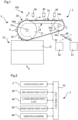
- FIG. 1 is a schematic front view illustrating one example of a drilling device to be used in the method for drilling an edible body of the present invention
- FIG. 2 is a block diagram of the drilling device illustrated in FIG. 1 .
- the drilling device 1 includes a conveying unit 2, a pre-detection unit 30, a laser irradiation unit 40, a post-detection unit 50, and a sorting damper 60.
- the pre-detection unit 30, the laser irradiation unit 40, the post-detection unit 50, and the sorting damper 60 are sequentially arranged along the conveyance direction of the conveying unit 2, and are operationally controlled by a control unit 70.
- FIG. 3 is a sectional view taken along line A-A of FIG. 1 .
- the conveying unit 2 includes a first conveying device 10 and a second conveying device 20.
- the first conveying device 10 includes a cap-like disk 11, an intermediate ring 12 that accommodates the disk 11, and a rotary ring 13 that accommodates the intermediate ring 12.
- the rotation shaft 12a of the intermediate ring 12 is disposed so as to be slightly tilted with respect to the rotation shafts 11a and 13a.
- the rotation shafts 11a, 12a, and 13a are connected to drive sources (not illustrated) such as motors individually provided via speed reducers 11b, 12b, and 13b, respectively, and can independently rotationally drive the disk 11, the intermediate ring 12, and the rotary ring 13.
- Conveying surfaces 12c and 13c are respectively formed on upper portions of the intermediate ring 12 and the rotary ring 13 along the circumferential direction.
- the radially outer side of the conveying surface 13c of the rotary ring 13 is covered with a ring-shaped protrusion 13d.
- the second conveying device 20 includes a first pulley 21 and a second pulley 22 in which rotation shafts 21a and 22a are arranged horizontally, an endless belt body 23 wrapped around the first pulley 21 and the second pulley 22, and a guide member 24 arranged along a conveyance direction of the belt body 23.
- a straight portion of the belt body 23 located between the first pulley 21 and the second pulley 22 is horizontally disposed above the first pulley 21 and the second pulley 22 to form a straight conveyance path 2a.
- the first pulley 21 is configured such that two circular plates 21b and 21c are connected by a rotation shaft 21a in a state of being spaced apart from each other.
- the second pulley 22 also includes two circular plates connected by the rotation shaft 22a with a space provided therebetween.
- the first pulley 21 or the second pulley 22 is driven by a drive motor (not illustrated).
- the encoder information of the drive motor is transmitted to the control unit 70.
- the belt body 23 includes two belt-shaped conveyance belts 23a and 23b, and the conveyance belts 23a and 23b are wrapped around the circular plates 21b and 21c of the first pulley 21, respectively. Between the two conveyance belts 23a and 23b, an opening 23c including a fine gap is formed throughout the circumference of the belt body 23.
- the conveyance belts 23a and 23b may be formed of, for example, flat belts made of a soft material such as silicone rubber.
- the guide member 24 includes a straight portion 24a disposed immediately below the vicinity of the belt body 23 extending horizontally along the conveyance path 2a between the first pulley 21 and the second pulley 22, and arcuate portions 24b and 24c provided on both sides of the straight portion 24a in the conveyance direction.
- the arcuate portions 24b and 24c are inserted between the pairs of circular plates of the first pulley 21 and the second pulley 22, respectively, and are formed to arcuately curve along the belt body 23 wrapped around the first pulley 21 and the second pulley 22.
- the guide member 24 is formed in a hollow cylindrical shape, and a slit-like suction part 25 is formed along the opening 23c in a portion where the guide member 24 faces the opening 23c of the belt body 23.
- the inside of the guide member 24 can be decompressed by the operation of a vacuum pump (not illustrated), and the edible body P can be conveyed together with the belt body 23 with the edible body P being attracted to the belt body 23 by sucking the edible body P to the suction part 25 through the opening 23c of the belt body 23.
- the opening 23c of the belt body 23 of the present embodiment is continuously formed between the two conveyance belts 23a and 23b along the longitudinal direction.
- the belt body 23 may be formed as a single band-like belt, and openings in such a shape as a circular shape, an elliptical shape, or a slit shape may be intermittently formed along the longitudinal direction of the band-like belt.
- the pre-detection unit 30 includes, for example, a CCD camera, and captures an image of the edible body conveyed by the second conveying device 20 to acquire pre-imaging data.
- the acquired pre-imaging data is used for defect inspection of the surface of the edible body, acquisition of position information of the edible body, setting of irradiation timing and laser scanning angle of the laser irradiation unit 40, and the like.
- the laser irradiation device 40 is a device that scans laser light emitted from a laser oscillator, and modifies or peels (engraves) a surface of the edible body by thermal energy to volatilize or scatter the surface, thereby drilling the surface of the edible body.
- a pulse laser device capable of controlling a pulse width can be suitably used.
- the type of the laser light is not necessarily limited, but it is preferable that the laser beam can drill the surface of the edible body accurately with a desired size and depth, and examples thereof include UV laser light and CO2 laser light.
- the post-imaging unit 50 includes, for example, a CCD camera, and captures an image of the edible body after drilling to acquire post-imaging data.
- the acquired post-imaging data is used for inspection of a drilling state, setting of a laser scanning angle of the laser irradiation unit 40, and the like.
- the sorting damper 60 is operationally controlled by the control unit 70 on the basis of the pre-imaging data of the pre-detection unit 30 and the post-imaging data of the post-imaging unit 50, and sorts edible bodies to a non-defective product box 61 and a defective product box 62.
- FIG. 4 is a sectional view schematically illustrating an osmotic pump type tablet, which is one example of such an edible body.
- a drug layer 101 containing an active ingredient and an expansion layer 102 that expands due to water absorption are covered with a semipermeable membrane 103, and the active ingredient of the drug layer 101 can be released from a release hole 104 at a desired speed by forming the release hole 104 with a prescribed dimensional accuracy in the semipermeable membrane 103 provided on the drug layer 101 side using a drilling device 1.
- the edible body P aligned and conveyed toward the second conveying device 20 by the first conveying device 10 is sequentially attracted to the belt body 23 and ascends in the vicinity of the lower portion of the first pulley 21 by the suction at the suction part 25, and is conveyed in the arrowed direction along the straight conveyance path 2a by the second conveying device 20 while maintaining the alignment state, and sequentially passes through the vicinity of the pre-detection unit 30, the laser irradiation unit 40, and the post-detection unit 50.
- control unit 70 controls the operation of the laser irradiation unit 40 at the timing when the edible body P passes near the laser irradiation unit 40, and performs desired drilling on the edible body P moving.
- the drilled edible body P is detected by the post-detection unit 50 and then conveyed toward the sorting device 60.
- the control unit 70 determines the presence or absence of a defect such as a chip or a crack of the edible body P and whether or not the position, shape, size, and the like of the drilled hole are appropriate on the basis of the detection by the pre-detection unit 30 and the post-detection unit 50, and sorts edible bodies P into non-defective products and defective products by the operation of the sorting device 60.
- a defect such as a chip or a crack of the edible body P and whether or not the position, shape, size, and the like of the drilled hole are appropriate on the basis of the detection by the pre-detection unit 30 and the post-detection unit 50, and sorts edible bodies P into non-defective products and defective products by the operation of the sorting device 60.
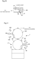
- FIG. 5 is a main part enlarged view illustrating a process of drilling an edible body P.
- the time required for the drilling can be calculated in advance from the conveyance speed of the edible body P, the scanning speed of the laser, the size and shape of a hole to be drilled, and the like.
- the distance L1 from the laser output position S to the edible body P at the start of the laser irradiation is matched with the distance L2 from the laser output position S to the edible body P at the end of the laser irradiation such that the laser irradiation direction is perpendicular to the conveyance direction at the intermediate time from the start time to the end time of the laser irradiation.
- the timing of laser irradiation on an edible body P is not necessarily limited to that of the present embodiment, and may be appropriately adjusted while viewing the state of drilling on the edible body P.
- a release hole having a desired size and depth it is possible to easily form a release hole having a desired size and depth by forming multiple closed curves on a surface of the edible body by laser scanning of a laser irradiation unit.
- a single release hole is formed on the surface of the edible body in the present embodiment, multiple release holes may be formed.
- FIG. 6 is a schematic diagram for explaining one example of a method for drilling an edible body, and illustrates a laser scanning trajectory on a surface of the edible body.
- the laser spot L is scanned so as to draw a circle from the scanning start position S1 of the surface of the edible body, and the irradiated portion is volatilized or scattered up to the scanning end position E1 illustrated in FIG. 6(b) , thereby forming a recess formed of an annular closed curve C1 as illustrated in FIG. 6(b) .
- the depth of the recess is preferably a depth at which the release hole 104 illustrated in FIG. 4 reaches the drug layer 101, and can be appropriately set according to the thickness of the semipermeable membrane 103 or the like, and is, for example, 100 to 1000 ⁇ m.
- the laser spot L is scanned along the inner circumference of the closed curve C1, and as illustrated in FIG. 6(d) , a recess formed of another closed curve C2 having the same depth as that of the closed curve C1 is formed inside the closed curve C1.
- the two closed curves C1 and C2 are formed so as to be in contact with each other in the line width direction, whereby a release hole 104 having a circular opening is formed as illustrated in FIG. 6(e) .
- the release hole 104 in a case where an undrilled portion is generated inside the closed curve C2, the release hole 104 can be reliably formed by applying laser irradiation to this portion as well.
- the diameter of the release hole 104 is appropriately set according to the release rate of the active ingredient contained in the edible body, and is, for example, 0.3 to 1 mm.
- Each of the closed curves C1 and C2 may be formed by laser irradiation so as to trace the same portion multiple times, whereby the closed curves C1 and C2 having a desired depth can be reliably obtained by gradually deepening the recess while reducing the laser energy to inhibit carbonization due to heat storage.
- the center of the laser spot may be scanned for 5 revolutions along a circumference having a diameter of 0.3 mm, and then scanned for 3 revolutions along a circumference having a diameter of 0.1 mm to form the release hole 104.
- the number of closed curves to be formed by laser irradiation may be three or more, and by forming multiple closed curves concentrically, a release hole 104 can be accurately formed at a desired position regardless of the size thereof.
- the scanning start position S2 of the other closed curve C2 is preferably a position farthest from the formation end position E1 of the closed curve C1, and in the present embodiment, the opposite side from the formation end position E1 across the center of the closed curve C1 is set as the scanning start position S2.
- the heat dissipation time may be provided during the formation of any one of the multiple closed curves C1 and C2, or may be provided between the formation of one closed curve C1 and the formation of the other closed curve C2.
- the average output of the laser light to be applied is preferably 10 to 300 W, and more preferably 30 to 60 W.
- the scanning speed of the laser light to be applied is preferably 100 to 5000 mm/s, and more preferably 500 to 3000 mm/s because when the scanning speed is excessively high, it is likely to be difficult to control the hole diameter and depth of the release hole, and when the scanning speed is excessively low, such problems as deterioration in production capacity and carbonization of fumes easily occur.
- the spot diameter of the laser light to be applied is excessively large, it is likely to be difficult to control the hole diameter and depth of the release hole. On the other hand, if the spot diameter is excessively small, production efficiency is likely to decrease. Therefore, the spot diameter is preferably 0.1 to 1 mm, and more preferably 0.3 to 0.6 mm.
- one closed curve C1 and the formation of the other closed curve C2 are not necessarily performed continuously.
- the laser spot L is scanned so as to draw a circle from the scanning start position S1 with the dot portion D1 as the center, whereby a recess formed of an annular closed curve C1 is formed as illustrated in FIG. 7(c) .
- the closed curve C1 may be formed by tracing the same portion multiple times.
- the laser spot L is scanned so as to draw a circle from the scanning start position S2 along the annular gap formed between the closed curve C1 and the dot portion D as illustrated in FIG. 7(e) .
- a recess formed of the closed curve C2 is formed between the closed curve C1 and the dot portion D, and a release hole 104 can be formed.
- the closed curve C2 may also be formed by tracing the same portion multiple times.
- a step of forming a recess formed of another pattern such as a straight pattern or a curved pattern by laser irradiation.
- another closed curve C2 is formed along the inner side of the closed curve C1.
- another closed curve C2 may be formed along the outside of the closed curve C1 as illustrated in FIG. 8(c) by scanning a laser spot L along the outer side of the closed curve C1 as illustrated in FIG. 8(b) .
- the shape of the closed curve C1 may be a shape other than an annular shape, for example, may be a rectangular shape illustrated in FIG. 9(a) , a polygonal shape illustrated in FIG. 9(b) , a cross shape illustrated in FIG. 9(c) , or the like, and the release hole can be formed by forming one or more other closed curves along the inner side or the outer side of the closed curve C1. Also in this case, a step of forming another pattern such as a dot portion may be provided between the steps of forming the multiple closed curves.
- the treatment capacity can be enhanced by performing the drilling during the conveyance of the edible body P, and the drilling can be performed while constantly moving the edible body P from the place where fumes are generated during the laser irradiation on the edible body P. Therefore, the problem that the laser irradiation of the edible body P is blocked by the fumes can be suppressed.
- a cover member 80 that covers the edible body P may be provided in the drilling device 1 illustrated in FIG. 1 as illustrated in FIG. 10 .
- FIG. 10 is a main part sectional view orthogonal to the conveyance direction of the edible body P to be subjected to laser irradiation.
- a suction path 81 connected to a suction device such as a vacuum pump and a passing hole 82 through which laser light passes are formed, and laser can be applied through the passing hole 82 to the edible body P whose upper side is covered by the suction path 81.
- the drilling device 1 illustrated in FIG. 1 is configured to apply laser irradiation to the edible body P being conveyed in a straight direction by the second conveying device 20.
- the second conveying device 20' of the conveying unit 2' is designed to be an adsorption drum capable of vacuum adsorbing the edible body P on the outer peripheral surface, so that laser can be applied to the edible body P being conveyed in a circumferential direction to perform drilling.
- the distance L1 from the laser output position to the edible body P at the start of the laser irradiation is made equal to the distance L2 from the laser output position to the edible body P at the end of the laser irradiation.
- the same components as those in FIG. 1 are denoted by the same reference signs.
- the conveying unit 2' may further include an adsorbing drum 120 that adsorbs the edible body P received from the second conveying device 20' to the outer peripheral surface on the downstream side in the conveyance direction of the second conveying device 20'.
- an adsorbing drum 120 Owing to arranging the pre-detection unit 130, the laser irradiation unit 140, and the post-detection unit 150 along the outer peripheral surface of the adsorbing drum 120, laser can be applied from the laser irradiation unit 140 to the edible body P being conveyed by the adsorbing drum 120. Owing to this configuration, it is possible to reliably form release holes in the semipermeable membrane 103 on the drug layer 101 side illustrated in FIG.
Landscapes
- Health & Medical Sciences (AREA)
- Engineering & Computer Science (AREA)
- Medicinal Chemistry (AREA)
- Chemical & Material Sciences (AREA)
- Public Health (AREA)
- Pharmacology & Pharmacy (AREA)
- Life Sciences & Earth Sciences (AREA)
- Animal Behavior & Ethology (AREA)
- General Health & Medical Sciences (AREA)
- Veterinary Medicine (AREA)
- Mechanical Engineering (AREA)
- Plasma & Fusion (AREA)
- Optics & Photonics (AREA)
- Physics & Mathematics (AREA)
- General Preparation And Processing Of Foods (AREA)
- Laser Beam Processing (AREA)
Applications Claiming Priority (2)
| Application Number | Priority Date | Filing Date | Title |
|---|---|---|---|
| JP2022142062 | 2022-09-07 | ||
| PCT/JP2023/025427 WO2024053238A1 (ja) | 2022-09-07 | 2023-07-10 | 可食体への穿孔方法 |
Publications (2)
| Publication Number | Publication Date |
|---|---|
| EP4501302A1 true EP4501302A1 (de) | 2025-02-05 |
| EP4501302A4 EP4501302A4 (de) | 2026-03-18 |
Family
ID=90192356
Family Applications (1)
| Application Number | Title | Priority Date | Filing Date |
|---|---|---|---|
| EP23862782.2A Pending EP4501302A4 (de) | 2022-09-07 | 2023-07-10 | Perforationsverfahren für essbaren körper |
Country Status (6)
| Country | Link |
|---|---|
| US (1) | US20260000579A1 (de) |
| EP (1) | EP4501302A4 (de) |
| JP (1) | JPWO2024053238A1 (de) |
| KR (1) | KR20250065549A (de) |
| CN (1) | CN119300800A (de) |
| WO (1) | WO2024053238A1 (de) |
Family Cites Families (6)
| Publication number | Priority date | Publication date | Assignee | Title |
|---|---|---|---|---|
| US4693895A (en) * | 1984-10-26 | 1987-09-15 | Alza Corporation | Colon delivery system |
| US5658474A (en) | 1994-12-16 | 1997-08-19 | Alza Corporation | Method and apparatus for forming dispenser delivery ports |
| JPH11342485A (ja) * | 1998-05-29 | 1999-12-14 | Nec Corp | レーザ加工機およびスルーホール・ブラインドビアホール用加工孔の形成方法 |
| CA2506048A1 (en) * | 2002-11-13 | 2004-05-27 | Ackley Machine Corporation | Laser unit, inspection unit, method for inspecting pellet-shaped articles and pharmaceutical article |
| CN106312333A (zh) * | 2016-10-09 | 2017-01-11 | 中国航空工业集团公司北京航空制造工程研究所 | 一种激光加工孔的方法以及系统 |
| CN112872598A (zh) * | 2021-01-19 | 2021-06-01 | 中国航空制造技术研究院 | 防止加工损伤的激光制孔方法 |
-
2023
- 2023-07-10 EP EP23862782.2A patent/EP4501302A4/de active Pending
- 2023-07-10 WO PCT/JP2023/025427 patent/WO2024053238A1/ja not_active Ceased
- 2023-07-10 US US18/869,201 patent/US20260000579A1/en active Pending
- 2023-07-10 JP JP2024545466A patent/JPWO2024053238A1/ja active Pending
- 2023-07-10 CN CN202380043907.3A patent/CN119300800A/zh active Pending
- 2023-07-10 KR KR1020247036709A patent/KR20250065549A/ko active Pending
Also Published As
| Publication number | Publication date |
|---|---|
| US20260000579A1 (en) | 2026-01-01 |
| WO2024053238A1 (ja) | 2024-03-14 |
| JPWO2024053238A1 (de) | 2024-03-14 |
| CN119300800A (zh) | 2025-01-10 |
| KR20250065549A (ko) | 2025-05-13 |
| EP4501302A4 (de) | 2026-03-18 |
Similar Documents
| Publication | Publication Date | Title |
|---|---|---|
| US7102741B2 (en) | Printing/inspection unit, method and apparatus for printing and/or inspecting and accepting/removing specified pellet-shaped articles from a conveyer mechanism | |
| KR101700113B1 (ko) | 이차전지용 전극 가공장치 | |
| CN105377501A (zh) | 可食用物的标记装置和方法 | |
| JP5281238B2 (ja) | 可食体用レーザマーキング装置 | |
| JP7330771B2 (ja) | ウエーハの生成方法およびウエーハの生成装置 | |
| JP2021133395A (ja) | レーザ加工装置 | |
| EP4501302A1 (de) | Perforationsverfahren für essbaren körper | |
| JP3908519B2 (ja) | レーザ加工システム | |
| KR101677154B1 (ko) | 단차 가공용 레이저 절단 장치 | |
| CN1176348C (zh) | 塑料膜的热封位置检测装置 | |
| TWI640038B (zh) | Processing method of laminated substrate | |
| CN113305446B (zh) | 激光加工装置 | |
| JP2013052686A (ja) | 可食体用レーザマーキング装置 | |
| KR20170000330A (ko) | 웨이퍼의 가공 방법 | |
| JP7170400B2 (ja) | 検査装置、検査方法、錠剤印刷装置および錠剤印刷方法 | |
| JP4349667B2 (ja) | バリ取り機 | |
| EP4275829B1 (de) | Kapselmarkierungsvorrichtung und -verfahren | |
| EP4070906B1 (de) | Vorrichtung und verfahren zum markieren essbarer objekte | |
| JP2017189749A (ja) | 物品選別装置 | |
| JP2010172791A (ja) | スピンコート装置およびスピンコート方法 | |
| JP3830809B2 (ja) | レーザ加工システム | |
| JP2018082109A (ja) | ガラス板の分割方法及び板状ワークの分割方法 | |
| KR102863208B1 (ko) | 로터리형 마늘 꼭지 제거 장치 | |
| EP0426069A2 (de) | Perforiergerät für zylindrische Artikel | |
| JP2000171414A (ja) | 軽量容器の内外面検査方法及び装置 |
Legal Events
| Date | Code | Title | Description |
|---|---|---|---|
| STAA | Information on the status of an ep patent application or granted ep patent |
Free format text: STATUS: THE INTERNATIONAL PUBLICATION HAS BEEN MADE |
|
| PUAI | Public reference made under article 153(3) epc to a published international application that has entered the european phase |
Free format text: ORIGINAL CODE: 0009012 |
|
| STAA | Information on the status of an ep patent application or granted ep patent |
Free format text: STATUS: REQUEST FOR EXAMINATION WAS MADE |
|
| 17P | Request for examination filed |
Effective date: 20241029 |
|
| AK | Designated contracting states |
Kind code of ref document: A1 Designated state(s): AL AT BE BG CH CY CZ DE DK EE ES FI FR GB GR HR HU IE IS IT LI LT LU LV MC ME MK MT NL NO PL PT RO RS SE SI SK SM TR |
|
| DAV | Request for validation of the european patent (deleted) | ||
| DAX | Request for extension of the european patent (deleted) | ||
| REG | Reference to a national code |
Ref country code: DE Ref legal event code: R079 Free format text: PREVIOUS MAIN CLASS: A61J0003070000 Ipc: A61J0003000000 |
|
| A4 | Supplementary search report drawn up and despatched |
Effective date: 20260217 |
|
| RIC1 | Information provided on ipc code assigned before grant |
Ipc: A61J 3/00 20060101AFI20260211BHEP Ipc: B23K 26/382 20140101ALI20260211BHEP |