EP4070906B1 - Vorrichtung und verfahren zum markieren essbarer objekte - Google Patents
Vorrichtung und verfahren zum markieren essbarer objekte Download PDFInfo
- Publication number
- EP4070906B1 EP4070906B1 EP20915470.7A EP20915470A EP4070906B1 EP 4070906 B1 EP4070906 B1 EP 4070906B1 EP 20915470 A EP20915470 A EP 20915470A EP 4070906 B1 EP4070906 B1 EP 4070906B1
- Authority
- EP
- European Patent Office
- Prior art keywords
- marking
- edible
- pattern
- orientation
- information
- Prior art date
- Legal status (The legal status is an assumption and is not a legal conclusion. Google has not performed a legal analysis and makes no representation as to the accuracy of the status listed.)
- Active
Links
Images


Classifications
-
- B—PERFORMING OPERATIONS; TRANSPORTING
- B23—MACHINE TOOLS; METAL-WORKING NOT OTHERWISE PROVIDED FOR
- B23K—SOLDERING OR UNSOLDERING; WELDING; CLADDING OR PLATING BY SOLDERING OR WELDING; CUTTING BY APPLYING HEAT LOCALLY, e.g. FLAME CUTTING; WORKING BY LASER BEAM
- B23K26/00—Working by laser beam, e.g. welding, cutting or boring
- B23K26/36—Removing material
- B23K26/362—Laser etching
-
- B—PERFORMING OPERATIONS; TRANSPORTING
- B23—MACHINE TOOLS; METAL-WORKING NOT OTHERWISE PROVIDED FOR
- B23K—SOLDERING OR UNSOLDERING; WELDING; CLADDING OR PLATING BY SOLDERING OR WELDING; CUTTING BY APPLYING HEAT LOCALLY, e.g. FLAME CUTTING; WORKING BY LASER BEAM
- B23K26/00—Working by laser beam, e.g. welding, cutting or boring
- B23K26/18—Working by laser beam, e.g. welding, cutting or boring using absorbing layers on the workpiece, e.g. for marking or protecting purposes
-
- A—HUMAN NECESSITIES
- A61—MEDICAL OR VETERINARY SCIENCE; HYGIENE
- A61J—CONTAINERS SPECIALLY ADAPTED FOR MEDICAL OR PHARMACEUTICAL PURPOSES; DEVICES OR METHODS SPECIALLY ADAPTED FOR BRINGING PHARMACEUTICAL PRODUCTS INTO PARTICULAR PHYSICAL OR ADMINISTERING FORMS; DEVICES FOR ADMINISTERING FOOD OR MEDICINES ORALLY; BABY COMFORTERS; DEVICES FOR RECEIVING SPITTLE
- A61J3/00—Devices or methods specially adapted for bringing pharmaceutical products into particular physical or administering forms
- A61J3/007—Marking tablets or the like
-
- A—HUMAN NECESSITIES
- A23—FOODS OR FOODSTUFFS; TREATMENT THEREOF, NOT COVERED BY OTHER CLASSES
- A23P—SHAPING OR WORKING OF FOODSTUFFS, NOT FULLY COVERED BY A SINGLE OTHER SUBCLASS
- A23P20/00—Coating of foodstuffs; Coatings therefor; Making laminated, multi-layered, stuffed or hollow foodstuffs
-
- B—PERFORMING OPERATIONS; TRANSPORTING
- B23—MACHINE TOOLS; METAL-WORKING NOT OTHERWISE PROVIDED FOR
- B23K—SOLDERING OR UNSOLDERING; WELDING; CLADDING OR PLATING BY SOLDERING OR WELDING; CUTTING BY APPLYING HEAT LOCALLY, e.g. FLAME CUTTING; WORKING BY LASER BEAM
- B23K26/00—Working by laser beam, e.g. welding, cutting or boring
- B23K26/02—Positioning or observing the workpiece, e.g. with respect to the point of impact; Aligning, aiming or focusing the laser beam
- B23K26/03—Observing, e.g. monitoring, the workpiece
- B23K26/032—Observing, e.g. monitoring, the workpiece using optical means
-
- B—PERFORMING OPERATIONS; TRANSPORTING
- B23—MACHINE TOOLS; METAL-WORKING NOT OTHERWISE PROVIDED FOR
- B23K—SOLDERING OR UNSOLDERING; WELDING; CLADDING OR PLATING BY SOLDERING OR WELDING; CUTTING BY APPLYING HEAT LOCALLY, e.g. FLAME CUTTING; WORKING BY LASER BEAM
- B23K26/00—Working by laser beam, e.g. welding, cutting or boring
- B23K26/08—Devices involving relative movement between laser beam and workpiece
- B23K26/082—Scanning systems, i.e. devices involving movement of the laser beam relative to the laser head
-
- B—PERFORMING OPERATIONS; TRANSPORTING
- B23—MACHINE TOOLS; METAL-WORKING NOT OTHERWISE PROVIDED FOR
- B23K—SOLDERING OR UNSOLDERING; WELDING; CLADDING OR PLATING BY SOLDERING OR WELDING; CUTTING BY APPLYING HEAT LOCALLY, e.g. FLAME CUTTING; WORKING BY LASER BEAM
- B23K26/00—Working by laser beam, e.g. welding, cutting or boring
- B23K26/08—Devices involving relative movement between laser beam and workpiece
- B23K26/0823—Devices involving rotation of the workpiece
-
- B—PERFORMING OPERATIONS; TRANSPORTING
- B23—MACHINE TOOLS; METAL-WORKING NOT OTHERWISE PROVIDED FOR
- B23K—SOLDERING OR UNSOLDERING; WELDING; CLADDING OR PLATING BY SOLDERING OR WELDING; CUTTING BY APPLYING HEAT LOCALLY, e.g. FLAME CUTTING; WORKING BY LASER BEAM
- B23K26/00—Working by laser beam, e.g. welding, cutting or boring
- B23K26/08—Devices involving relative movement between laser beam and workpiece
- B23K26/083—Devices involving movement of the workpiece in at least one axial direction
- B23K26/0838—Devices involving movement of the workpiece in at least one axial direction by using an endless conveyor belt
-
- B—PERFORMING OPERATIONS; TRANSPORTING
- B23—MACHINE TOOLS; METAL-WORKING NOT OTHERWISE PROVIDED FOR
- B23K—SOLDERING OR UNSOLDERING; WELDING; CLADDING OR PLATING BY SOLDERING OR WELDING; CUTTING BY APPLYING HEAT LOCALLY, e.g. FLAME CUTTING; WORKING BY LASER BEAM
- B23K26/00—Working by laser beam, e.g. welding, cutting or boring
- B23K26/352—Working by laser beam, e.g. welding, cutting or boring for surface treatment
- B23K26/355—Texturing
-
- B—PERFORMING OPERATIONS; TRANSPORTING
- B41—PRINTING; LINING MACHINES; TYPEWRITERS; STAMPS
- B41F—PRINTING MACHINES OR PRESSES
- B41F17/00—Printing apparatus or machines of special types or for particular purposes, not otherwise provided for
- B41F17/36—Printing apparatus or machines of special types or for particular purposes, not otherwise provided for for printing on tablets, pills, or like small articles
-
- B—PERFORMING OPERATIONS; TRANSPORTING
- B41—PRINTING; LINING MACHINES; TYPEWRITERS; STAMPS
- B41F—PRINTING MACHINES OR PRESSES
- B41F33/00—Indicating, counting, warning, control or safety devices
- B41F33/0081—Devices for scanning register marks
-
- B—PERFORMING OPERATIONS; TRANSPORTING
- B41—PRINTING; LINING MACHINES; TYPEWRITERS; STAMPS
- B41J—TYPEWRITERS; SELECTIVE PRINTING MECHANISMS, i.e. MECHANISMS PRINTING OTHERWISE THAN FROM A FORME; CORRECTION OF TYPOGRAPHICAL ERRORS
- B41J2/00—Typewriters or selective printing mechanisms characterised by the printing or marking process for which they are designed
- B41J2/435—Typewriters or selective printing mechanisms characterised by the printing or marking process for which they are designed characterised by selective application of radiation to a printing material or impression-transfer material
- B41J2/475—Typewriters or selective printing mechanisms characterised by the printing or marking process for which they are designed characterised by selective application of radiation to a printing material or impression-transfer material for heating selectively by radiation or ultrasonic waves
- B41J2/4753—Typewriters or selective printing mechanisms characterised by the printing or marking process for which they are designed characterised by selective application of radiation to a printing material or impression-transfer material for heating selectively by radiation or ultrasonic waves using thermosensitive substrates, e.g. paper
-
- B—PERFORMING OPERATIONS; TRANSPORTING
- B23—MACHINE TOOLS; METAL-WORKING NOT OTHERWISE PROVIDED FOR
- B23K—SOLDERING OR UNSOLDERING; WELDING; CLADDING OR PLATING BY SOLDERING OR WELDING; CUTTING BY APPLYING HEAT LOCALLY, e.g. FLAME CUTTING; WORKING BY LASER BEAM
- B23K2101/00—Articles made by soldering, welding or cutting
- B23K2101/007—Marks, e.g. trade marks
-
- B—PERFORMING OPERATIONS; TRANSPORTING
- B41—PRINTING; LINING MACHINES; TYPEWRITERS; STAMPS
- B41J—TYPEWRITERS; SELECTIVE PRINTING MECHANISMS, i.e. MECHANISMS PRINTING OTHERWISE THAN FROM A FORME; CORRECTION OF TYPOGRAPHICAL ERRORS
- B41J2/00—Typewriters or selective printing mechanisms characterised by the printing or marking process for which they are designed
- B41J2/435—Typewriters or selective printing mechanisms characterised by the printing or marking process for which they are designed characterised by selective application of radiation to a printing material or impression-transfer material
- B41J2/44—Typewriters or selective printing mechanisms characterised by the printing or marking process for which they are designed characterised by selective application of radiation to a printing material or impression-transfer material using single radiation source per colour, e.g. lighting beams or shutter arrangements
- B41J2/442—Typewriters or selective printing mechanisms characterised by the printing or marking process for which they are designed characterised by selective application of radiation to a printing material or impression-transfer material using single radiation source per colour, e.g. lighting beams or shutter arrangements using lasers
Definitions
- This invention relates to an edible-body marking device and a method to form a marking pattern on edible bodies such as medicine or food.
- Patent Document 1 Known as a conventional edible-body marking device is a configuration disclosed in Patent Document 1 for example.
- This marking device is provided with a carrying means to carry edible bodies, a detection means to detect edible bodies, and a marking means to form a marking pattern on edible bodies by laser light scanning, and configured so that edible bodies carried by the carrying means are imaged by the detection means to acquire orientation data of the edible bodies, and the marking means forms a preset marking pattern according to the orientations of the edible bodies according to the orientation data.
- Patent Literature 2 provides an edible object marking apparatus and method for forming a marking pattern on edible objects such as pharmaceutical products and food products.
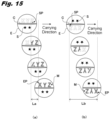
- marking start and end points are preset so as to allow an efficient formation within a short time.
- the orientation of the carried tablet E is random, as shown in Fig. 15b , if the orientation of the tablet E is vertically reversed, thereby the tablet E moves in the opposite direction of the order of "XYZ", the moving distance Lb of the tablet E while scanning is performed from the start point SP to the end point EP becomes longer, therefore the formation of the marking pattern M could take a longer time.
- the moving speed of the tablet E is increased for reducing the formation time of the marking pattern M, the scanning speed of laser light needs to be increased accordingly, causing a problem that marking quality declines.
- the objective of this invention is to offer an edible-body marking device and a method that can perform laser marking swiftly and precisely regardless of the orientations of edible bodies.
- an edible-body marking device comprises a carrier device that carries an edible body, a detection part that detects the edible body, and a laser processing part that forms a marking pattern on the edible body by using laser light, wherein the carrier device sequentially carries the edible body to the detection part and the laser processing part.
- the detection part images the edible body to acquire orientation information regarding an orientation of the edible body
- the laser processing part has a memory part that stores in advance multiple pieces of marking procedure information regarding formation procedures of the marking pattern in association with their respectively different pieces of the orientation information, and forms the marking pattern on the edible body according to the marking procedure information extracted from the memory part based on the orientation information acquired by the detection part.
- the multiple pieces of the marking procedure information preferably have mutually different marking start points in the marking patterns.
- the multiple pieces of marking procedure information each preferably have the marking start points set on a downstream side of a center of the edible body in a carrying direction.
- the detection part preferably further acquires position information regarding a position of the edible body, and the laser processing part is able to form the marking pattern on the edible body based on the orientation information and the position information.
- the laser processing part is able to form the marking pattern on the edible body that is packaged in a transparent packaging material through which the laser light is transmitted.
- an edible-body marking method comprises a detection step that detects an edible body carried by a carrier device, and a marking step that form a marking pattern on the edible body.
- the detection step images the edible body to acquire orientation information regarding an orientation of the edible body, and the marking step forms the marking pattern on the edible body according to marking procedure information extracted based on the orientation information acquired in the detection step from a memory part that memorizes multiple pieces of marking procedure information in association with respectively different pieces of the orientation information.
- the marking step is able to form the marking pattern on the edible body that is packaged in a transparent packaging material through which the laser light is transmitted.
- the edible-body marking device and method of this invention allow swift and precise laser marking regardless of the orientations of edible bodies.
- Fig. 1 is an outline configuration diagram of an edible-body marking device of an embodiment of this invention.
- the edible-body marking device 1 is provided with a supply device 10 that supplies edible bodies, a first carrier device 20 that receives edible bodies supplied from the supply device 10 and carries them, a second carrier device 30 that receives edible bodies from the first carrier device 20 and carries them, and a discharge device 40 that receives edible bodies from the second carrier device 30 and discharges them to the outside.
- the supply device 10 is provided with a hopper 11 into which thrown are edible bodies having a regular shape such as tablet, capsule, or empty capsule, a feeder 12 that aligns edible bodies inside the hopper 11, and a supply drum 13 that carries edible bodies guided by the feeder 12, and edible bodies are supplied from the supply drum 13 to the first carrier device 20 via an intermediate drum 14.
- the supply drum 13 and the intermediate drum 14 are provided with many holding parts 13a or 14a made of recesses aligned along the axial direction and the circumferential direction of their cylindrical outer circumferential faces, allowing them to suction-hold and carry edible bodies accommodated in their holding parts 13a or 14a, respectively.
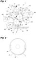
- the first carrier device 20 is formed in a drum shape in the same manner as the supply drum 13 and the intermediate drum 14, and as shown partially cut out in Fig. 2 , many holding parts 22 that hold edible bodies E are installed with equal intervals along both the circumferential direction and the axial direction.
- Each holding part 22 has a suction hole 24 formed on its bottom, and can suction-hold an edible body E accommodated in the holding part 22 through the suction hole 24 by depressurizing the interior of the first carrier device 20 and carry the edible body E along the rotational direction of the first carrier device 20 while preventing the orientation of the edible body E from changing while carrying it.
- the second carrier device 30 is configured in the same manner as the first carrier device 20, having holding parts 32 formed on its drum-shaped outer circumferential face. Edible bodies carried by the first carrier device 20 are front-back reversed when they are handed over to the second carrier device 30, and are carried to the discharge device 40.
- a first detection part 210, a first laser processing part 220, and a first marking inspection part 230 are installed in the vicinity of the first carrier device 20 sequentially along the carrying direction of the first carrier device 20.
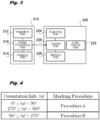
- Fig. 3 is a block diagram of the first detection part 210 and the first laser processing part 220.
- the first detection part 210 is provided with an irradiation part 212 that irradiates edible bodies carried to a detection area A1 with illumination light, an imaging part 214 such as a CCD area camera or CCD line camera that images edible bodies from a different direction from the irradiation direction of the irradiation part 212, and an image processing part 216 that processes image information of edible bodies imaged by the imaging part 214 to acquire orientation information of the edible bodies.
- an imaging part 214 such as a CCD area camera or CCD line camera that images edible bodies from a different direction from the irradiation direction of the irradiation part 212
- an image processing part 216 that processes image information of edible bodies imaged by the imaging part 214 to acquire orientation information of the edible bodies.
- the irradiation part 212 is a ring lighting for example, and can irradiate each edible body uniformly from its whole circumference.
- orientation information of the edible body can be acquired in the image processing part 216 based on an image of the dividing line of the edible body acquired by the imaging part 214.
- orientation information is not particularly limited as far as it can identify the orientation of each edible body, in this embodiment it is an angle indicating the orientation of a dividing line relative to the carrying direction and set within a range of 0-360 degrees. Distinguishing the upper and lower parts of each edible body across its dividing line (e. g., judging whether orientation information is 0 degree or 180 degrees) can utilize its characteristic such as engraving or a mark formed on the edible body, or its outer shape if the edible body has a heteromorphic outer shape (such as a tear shape).
- detecting the orientation of each edible body is not limited to the method that detects its divining line. For example, if multiple recesses are formed on the edible body, these recesses can be utilized as alignment marks to detect its orientation. Also, if the form of each edible body is non-circular such as polygonal or elliptical, the orientation of the edible body can be detected from part or the whole of its outline. Position information and orientation information regarding the position and orientation of edible bodies detected in the first detection part 210 are individually associated with the arrangement of edible bodies on the first carrier device 20 and output to the first laser processing part 220 and the first marking inspection part 230 by Ethernet communication, serial communication, or the like.
- the first laser processing part 220 is provided with a light source part 222 that emits laser light, a scanning part 224 that scans laser light emitted from the light source part 222 by a Galvano scanner, a memory part 226 that memorizes information on a marking pattern, and a control part 228 that controls the output of the light source part 222 and the scanning by the scanning part 224, and can perform marking by laser-spot scanning of edible bodies carried to a marking area A2.
- the memory part 226 is built in the first laser processing part 220, a memory device separate from the first laser processing part 220 can be utilized.
- Laser light emitted from the light source part 222 should preferably enter the surface of each edible body approximately vertically, thereby variation in laser-irradiated area on the surface of the edible body is minimized, suppressing variation in marking density, etc.
- laser light emitted from the light source part 222 are solid laser light such as YVO 4 laser light, YLF laser light, or YAG laser light, gas laser light such as excimer laser light or carbon dioxide laser light, and liquid laser light such as dye laser light.
- solid laser light such as YVO 4 laser light, YLF laser light, or YAG laser light
- gas laser light such as excimer laser light or carbon dioxide laser light
- liquid laser light such as dye laser light.
- discoloration-inducing oxide such as titanium oxide, yellow iron sesquioxide, or iron sesquioxide
- marking can also be performed by shaving part of its surface, and is not particularly limited.
- the marking pattern memorized in the memory part 226 is, for example, a character, symbol, shape, or their combination, and stored in advance as coordinate information in a reference coordinate system.
- the control part 228 converts the coordinate information in the reference coordinate system into coordinate information in a processing coordinate system based on position and orientation information of each edible body input from the first detection part 210, and controls driving the scanning part 224 in this processing coordinate system, thereby forming the marking pattern according to the orientation of the edible body.
- the memory part 226 memorizes marking procedure information in association with orientation information.
- the marking procedure information is information on the forming procedure of a marking pattern, and if the marking pattern is formed in a one-stroke drawing manner for example, it contains coordinate information in the reference coordinate system of the marking start and end points, on/off information of the light source part 222 for forming blanks between characters, etc. Multiple pieces of marking procedure information having different marking start points are memorized in association with orientation information so as to efficiently form the marking(s) according to the orientation of each edible body.
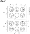
- Fig. 4 is a diagram showing an example of marking procedure information table memorized in the memory part 226.
- the marking procedure information table shown in Fig. 4 two marking procedures (procedures A and B) having different start points are associated with angle ranges of orientation information.
- the first marking inspection part 230 is provided with an irradiation part 232 that irradiates edible bodies carried to an inspection area A3 with illumination light, and an imaging part 234 such as a CCD area camera or CCD line camera that images edible bodies.
- the irradiation part 232 should preferably irradiate them so as to clarify a marking pattern formed on the surface of each edible body, and for example, diffuses irradiation light from a light source such as LEDs by a diffusing light-guiding plate to induce surface emission.
- the first marking inspection part 230 has reference pattern information corresponding to the marking pattern stored in advance in the memory part, extracts marking pattern information from information acquired by the imaging part 234 imaging edible bodies, and compares it with the reference pattern information based on orientation information input from the first detection part 210, thereby inspecting marking accuracy of edible bodies. Because the preset reference pattern information is set in the reference coordinate system, after correcting the marking pattern information (or correcting the reference pattern information) based on position information and orientation information of edible bodies input from the first detection part 210, the marking pattern information is compared with the reference pattern information to perform pattern matching etc.
- a second detection part 310 installed in the vicinity of the second carrier device 30 are a second detection part 310, a second laser processing part 320, and a second marking inspection part 330 sequentially along the carrying direction of the second carrier device 30.
- the configurations of the second detection part 310, the second laser processing part 320, and the second marking inspection part 330 are the same as the configurations of the first detection part 210, the first laser processing part 220, and the first marking inspection part 230, where the second detection part 310 is provided with an irradiation part 312 and an imaging part 314, and the second marking inspection part 330 is provided with an irradiation part 332 and an imaging part 334.
- the second carrier device 30 receives edible bodies from the first carrier device 20 and carries them, and the second laser processing part 320 performs marking on the opposite face from the face where a marking pattern was formed while being carried by the first carrier device 20.
- the discharge device 40 is provided with a sorting part 42 that sorts edible bodies based on the results of marking inspections in the first marking inspection part 230 and the second marking inspection part 330, and only good products are guided to a discharge conveyer 44 to be discharged.
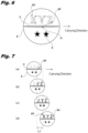
- Edible bodies E supplied from the supply device 10 to the first carrier device 20 shown in Fig. 1 are individually accommodated in the holding parts 22 so as to be aligned in the axial direction of the first carrier device 20 as shown in Fig. 5a .
- the orientations of a dividing line C and engraved marks S formed on each edible body E are random.
- the imaging part 214 images the edible bodies E in each row for their image information, and the image processing part 216 acquires orientation information of the edible bodies E based on the image information containing the dividing line C and the engraved marks S.
- the acquired orientation information is sent to the first laser processing part 220. Note that for any edible body E whose acquired image information has no dividing line C, such fact is output instead of orientation information.
- marking is performed according to the orientation of each edible body E, forming a marking pattern M1 along the dividing line C.
- the formation procedure of the marking pattern M1 is determined based on orientation information of the edible body E according to the marking procedure information table shown in Fig. 4 .
- the procedure A is selected from the marking procedure information table, and as shown in Fig. 6 , the laser irradiation point moves from its origin O that is the center of the edible body E to the start point SP as indicated with a broken arrow to start marking, and marking is performed until the end point EP intervened with marking-off periods indicated with broken arrows, thereby marking with "Z", "Y", and "X” in that order.
- marking procedure information By marking an edible body E carried as shown in Figs. 7a-d according to this marking procedure information, forming the marking pattern M1 can be completed with a short moving distance L1.
- the procedure B is selected from the marking procedure information table shown in Fig. 4 , and as shown in Fig. 8 , the start point SP and the end point EP are set so that marking is performed in the order of "X", "Y", and "Z".
- marking procedure information By marking an edible body E carried as shown in Figs. 9a-d according to this marking procedure information, forming the marking pattern M1 can be completed with a short moving distance L2 in this case as well.
- the marking pattern M1 only needs to be formed considering the orientation of the dividing line C and need not necessarily be formed along the dividing line C as far as it does not overlap with the dividing line for example.
- a marking pattern M2 that is different from the above-mentioned marking pattern M1 may be formed, or no marking pattern may be formed.
- orientation information can be set to a range of 0-180 degrees.
- marking procedure information table shown in Fig. 4 for example, two kinds of procedures can be set for the case of 0 degree or greater and smaller than 45 degrees or 135 degrees or greater and smaller than 180 degrees, and the case of 45 degrees or greater and smaller than 135 degrees.
- the imaging part 234 acquires image information of the edible bodies E in each row Afterwards, inclination of marking pattern information is corrected based on the orientation information acquired by the first detection part 210, the corrected marking pattern information is compared with the preset reference pattern information, and marking precision is inspected by a publicly-known inspection method such as pattern matching.
- the edible bodies E are handed from the first carrier device 20 over to the second carrier device 30, and sequentially carried to the second detection part 310, the second laser processing part 320, and the second marking inspection part 330, thereby marking and marking inspection are performed on the other face of the edible bodies E in the same manner as mentioned above.
- marking on edible bodies is performed according to the marking procedure information extracted based on the orientation information acquired by the second detection part 310, and in the second marking inspection part 330 a marking precision inspection is performed based on the orientation information acquired by the second detection part 310.
- marking and marking inspection can be performed based on the orientation information acquired by the first detection part 210, thereby marking directions on the front and back of edible bodies can be matched.
- the edible bodies E are carried from the second carrier device 30 to the discharge device 40.
- marking quality judgement information of each edible body E is input from the first marking inspection part 230 and the second marking inspection part 330, and edible bodies E judged as good are guided to the discharge conveyer 44 via the sorting part 42 while edible bodies E judged as bad are blown out by air in a bad product discharge part 45 and guided to a bad product discharge chute 46.
- a bad product discharge checking sensor 47 checks whether any edible body E judged as bad remains in the second carrier device 30, and if a bad edible body E remains, it is guided to a waste chute 48 in the sorting part 42.
- the marking procedure information memorized in the memory part 226 has two procedures A and B, it is not particularly limited as far as there are multiple procedures.
- the marking procedure information memorized in the memory part 226 has two procedures A and B, it is not particularly limited as far as there are multiple procedures.
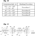
- characters "XYZ" and "ABC" are printed on both sides across the dividing line of each edible body, as in a marking procedure information table shown in Fig. 10 , four pieces of marking procedure information (procedures C-F) can be associated with orientation information at every 90 degrees.
- Figs. 1a-d correspond to the procedures C-F in Fig. 10 , having mutually different start points SP in their marking patterns.
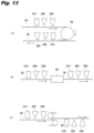
- Figs. 12a-d show edible bodies marked according to the marking procedures C-F when orientation information is 0, 90, 180, or 270 degrees, respectively.
- Each marking procedure information should preferably have the marking start point set on the downstream side of the center of each edible body (origin) in the carrying direction (e. g., the right side of the origin O in Fig. 8 ), thereby swift marking can be securely performed.
- both the first carrier device 20 and the second carrier device 30 are made carrier drums in this embodiment, another configuration can be adopted as far as the posture of each edible body held does not change while being carried.
- both the first carrier device 20 and the second carrier device 30 can be made conveyer devices such as slat conveyers or belt conveyers, and edible bodies carried horizontally by the first carrier device 20 can be front-back reversed by a reversing mechanism 60 and mounted and carried horizontally on the second carrier device 30, thereby marking can be performed on both the front and back faces of the edible bodies in the same manner as in this embodiment.
- conveyer devices such as slat conveyers or belt conveyers
- edible bodies carried horizontally by the first carrier device 20 can be front-back reversed by a reversing mechanism 60 and mounted and carried horizontally on the second carrier device 30, thereby marking can be performed on both the front and back faces of the edible bodies in the same manner as in this embodiment.
- the second carrier device 30 can be configured of a suction belt having suction holes that allow vacuum suction of edible bodies from above, the edible bodies carried horizontally from the first carrier device 20 can be suction-held by the second carrier device 30, and marking can be performed from below, thereby marking can be performed on both the front and back faces of the edible bodies.
- the same codes are given to the same components as in Fig. 1 .
- the first detection part 210, the first laser processing part 220, and the first marking inspection part 230 need not be arranged along the same carrier drum (or conveyer device). For example, in the edible-body marking device 1 shown in Fig.
- a new carrier drum or the like can be placed between the supply device 10 and the first carrier device 20, and a new detection device can be installed so as to detect one face of edible bodies carried by this carrier drum to acquire orientation information of the edible bodies.
- marking and marking inspection can be performed on the other face of the edible bodies based on the orientation information acquired from the one face of the edible bodies, thereby even if the marking target face has nothing to indicate its orientation such as a dividing line, marking can be performed according to the orientations of the edible bodies.
- Forming a marking pattern on edible bodies by the first laser processing part 220 (or the second laser processing part 320) can also be performed to edible bodies such as PTP packaged in a transparent packaging material (such as transparent plastic) that transmits laser light, where marking procedure information can be extracted based on orientation information acquired by the first detection part 210 (or the second detection part 310) through the packaging material, and a marking pattern can be formed on the edible bodies through the packaging material.
- the kind of laser light in this case can also be selected as appropriate according to the packaging material etc. from those mentioned above.
- the edible body marking device 1 can be configured so as to perform marking only while the edible bodies are being carried by the first carrier device 20 without being provided with the second carrier device 30, the second detection part 310, the second laser processing part 320, or the second marking inspection part 330 placed in its vicinity.
- the edible body marking device 1 in this embodiment has a multiple-row system where the first carrier device 20 and the second carrier device 30 are provided with multiple holding parts 22 in the rotation axis direction, it can have a configuration where edible bodies are carried one by one.
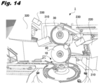
- Fig. 14 is an outline configuration diagram showing an example such single-row system marking device, and the same codes are given to the components having the same functions as those in Fig. 1 .
- the edible-body marking device 1 shown in Fig. 14 is a carrier device where a supply device 10 aligns edible bodies by the rotation of a rotating disk, and a first carrier device 20 and a second carrier device 30 each comprise a suction roller that vacuum-sucks edible bodies to their respective outer circumferential faces.
- a first carrier device 20 and a second carrier device 30 each comprise a suction roller that vacuum-sucks edible bodies to their respective outer circumferential faces.
- edible bodies aligned into a single row by the supply device 10 are carried upwards as the single row by the first carrier device 20 and the second carrier device 30, and marking is performed onto their front and back faces by a first laser processing part 220 and a second laser processing part 320.
- the carrying speed of edible bodies should preferably be as high as possible for swift and efficient marking, and preferably be set within a range of 100-2000 mm/sec (SI unit-symbol "mms -1 ”) for example.
Landscapes
- Engineering & Computer Science (AREA)
- Physics & Mathematics (AREA)
- Optics & Photonics (AREA)
- Mechanical Engineering (AREA)
- Plasma & Fusion (AREA)
- Health & Medical Sciences (AREA)
- Chemical & Material Sciences (AREA)
- Life Sciences & Earth Sciences (AREA)
- General Health & Medical Sciences (AREA)
- Polymers & Plastics (AREA)
- Food Science & Technology (AREA)
- Public Health (AREA)
- Medicinal Chemistry (AREA)
- Pharmacology & Pharmacy (AREA)
- Animal Behavior & Ethology (AREA)
- Toxicology (AREA)
- Veterinary Medicine (AREA)
- Laser Beam Processing (AREA)
- Thermal Transfer Or Thermal Recording In General (AREA)
- Medical Preparation Storing Or Oral Administration Devices (AREA)
- General Preparation And Processing Of Foods (AREA)
- Control And Other Processes For Unpacking Of Materials (AREA)
Claims (7)
- Vorrichtung (1) zum Markieren eines essbaren Körpers, umfassend:eine Trägervorrichtung (20), die dafür eingerichtet ist, einen essbaren Körper zu tragen,einen Detektionsteil (210), der dafür eingerichtet ist, den essbaren Körper zu detektieren, undeinen Laserbearbeitungsteil (220), der dafür eingerichtet ist, unter Verwendung von Laserlicht ein Markierungsmuster auf dem essbaren Körper zu bilden, wobei die Trägervorrichtung (20) dafür eingerichtet ist, den essbaren Körper nacheinander zu dem Detektionsteil (210) und dem Laserbearbeitungsteil (220) zu tragen, wobeider Detektionsteil (210) den essbaren Körper abbildet, um Ausrichtungsinformationen bezüglich einer Ausrichtung des essbaren Körpers zu erhalten, unddadurch gekennzeichnet, dassder Laserbearbeitungsteil (220)einen Speicherteil (226) aufweist, der im Voraus mehrere Markierungsverfahrensinformationen bezüglich Bildungsverfahren des Markierungsmusters in Verbindung mit ihren jeweiligen verschiedenen Ausrichtungsinformationen speichert, unddas Markierungsmuster auf dem essbaren Körper gemäß den aus dem Speicherteil (226) extrahierten Markierungsverfahrensinformationen auf der Grundlage der durch den Detektionsteil (210) erfassten Ausrichtungsinformationen bildet.
- Vorrichtung (1) zum Markieren eines essbaren Körpers nach Anspruch 1, wobei
die mehreren Markierungsverfahrensinformationen voneinander verschiedene Markierungsstartpunkte in dem Markierungsmuster aufweisen. - Vorrichtung (1) zum Markieren eines essbaren Körpers nach einem der Ansprüche 1 oder 2, wobei
die mehreren Markierungsverfahrensinformationen jeweils die Markierungsstartpunkte haben, die auf einer stromabwärtigen Seite einer Mitte des essbaren Körpers in einer Tragerichtung eingestellt sind. - Vorrichtung (1) zum Markieren eines essbaren Körpers nach einem der Ansprüche 1 bis 3, wobeider Detektionsteil (210) des Weiteren Positionsinformationen bezüglich einer Position des essbaren Körpers erfasst undder Laserbearbeitungsteil (220) das Markierungsmuster auf dem essbaren Körper auf der Grundlage der Ausrichtungsinformationen und der Positionsinformationen bildet.
- Vorrichtung (1) zum Markieren eines essbaren Körpers nach Anspruch 1, wobeider essbare Körper in ein transparentes Verpackungsmaterial verpackt ist, das das Laserlicht durchlässt undder Laserbearbeitungsteil (220) das Markierungsmuster auf dem essbaren Körper durch das Verpackungsmaterial hindurch bildet.
- Verfahren zum Markieren eines essbaren Körpers, umfassend:einen Detektionsschritt, der einen essbaren Körper detektiert, der durch eine Trägervorrichtung (20) getragen wird, undeinen Markierungsschritt, der ein Markierungsmuster auf dem essbaren Körper bildet, wobeider Detektionsschritt den essbaren Körper abbildet, um Ausrichtungsinformationen bezüglich einer Ausrichtung des essbaren Körpers zu erhalten, unddadurch gekennzeichnet, dassder Markierungsschritt das Markierungsmuster auf dem essbaren Körper gemäß Markierungsverfahrensinformationen bildet, die auf der Grundlage der Ausrichtungsinformationen extrahiert werden, die in dem Detektionsschritt aus einem Speicherteil (226) erfasst wurden, der mehrere Markierungsverfahrensinformationen in Verbindung mit jeweils verschiedenen Ausrichtungsinformationen speichert.
- Verfahren zum Markieren eines essbaren Körpers nach Anspruch 6, wobei
der essbare Körper in ein transparentes Verpackungsmaterial verpackt wird, das Laserlicht durchlässt, und der Markierungsschritt das Markierungsmuster auf dem essbaren Körper durch das Verpackungsmaterial hindurch bildet.
Priority Applications (1)
| Application Number | Priority Date | Filing Date | Title |
|---|---|---|---|
| EP24181664.4A EP4403363A3 (de) | 2020-01-21 | 2020-12-25 | Vorrichtung zur markierung eines essbaren körpers und verfahren dafür |
Applications Claiming Priority (2)
| Application Number | Priority Date | Filing Date | Title |
|---|---|---|---|
| JP2020007238 | 2020-01-21 | ||
| PCT/JP2020/048655 WO2021149454A1 (ja) | 2020-01-21 | 2020-12-25 | 可食体のマーキング装置および方法 |
Related Child Applications (2)
| Application Number | Title | Priority Date | Filing Date |
|---|---|---|---|
| EP24181664.4A Division-Into EP4403363A3 (de) | 2020-01-21 | 2020-12-25 | Vorrichtung zur markierung eines essbaren körpers und verfahren dafür |
| EP24181664.4A Division EP4403363A3 (de) | 2020-01-21 | 2020-12-25 | Vorrichtung zur markierung eines essbaren körpers und verfahren dafür |
Publications (3)
| Publication Number | Publication Date |
|---|---|
| EP4070906A1 EP4070906A1 (de) | 2022-10-12 |
| EP4070906A4 EP4070906A4 (de) | 2023-11-22 |
| EP4070906B1 true EP4070906B1 (de) | 2024-10-30 |
Family
ID=76992306
Family Applications (2)
| Application Number | Title | Priority Date | Filing Date |
|---|---|---|---|
| EP20915470.7A Active EP4070906B1 (de) | 2020-01-21 | 2020-12-25 | Vorrichtung und verfahren zum markieren essbarer objekte |
| EP24181664.4A Pending EP4403363A3 (de) | 2020-01-21 | 2020-12-25 | Vorrichtung zur markierung eines essbaren körpers und verfahren dafür |
Family Applications After (1)
| Application Number | Title | Priority Date | Filing Date |
|---|---|---|---|
| EP24181664.4A Pending EP4403363A3 (de) | 2020-01-21 | 2020-12-25 | Vorrichtung zur markierung eines essbaren körpers und verfahren dafür |
Country Status (7)
| Country | Link |
|---|---|
| US (1) | US20230038031A1 (de) |
| EP (2) | EP4070906B1 (de) |
| JP (2) | JP7515523B2 (de) |
| KR (2) | KR102592475B1 (de) |
| CN (1) | CN115003447B (de) |
| ES (1) | ES3001525T3 (de) |
| WO (1) | WO2021149454A1 (de) |
Families Citing this family (1)
| Publication number | Priority date | Publication date | Assignee | Title |
|---|---|---|---|---|
| KR102271655B1 (ko) | 2020-06-12 | 2021-07-05 | (주)엔클로니 | 정제에 대한 인쇄 및 검사를 수행하는 정제 인쇄 겸 검사 장치 및 방법 |
Family Cites Families (10)
| Publication number | Priority date | Publication date | Assignee | Title |
|---|---|---|---|---|
| JP4187472B2 (ja) * | 2002-07-15 | 2008-11-26 | 株式会社キーエンス | 光学式情報読取装置およびその操作方法 |
| JP5281238B2 (ja) * | 2006-11-24 | 2013-09-04 | エーザイ・アール・アンド・ディー・マネジメント株式会社 | 可食体用レーザマーキング装置 |
| JP5469389B2 (ja) | 2009-07-15 | 2014-04-16 | 株式会社京都製作所 | 錠剤印刷方法および錠剤印刷装置 |
| JP2011212727A (ja) | 2010-03-31 | 2011-10-27 | Panasonic Electric Works Sunx Co Ltd | レーザ加工装置 |
| JP2013122401A (ja) | 2011-12-09 | 2013-06-20 | Kyoto Seisakusho Co Ltd | 画像処理システム |
| JP5813556B2 (ja) * | 2012-03-30 | 2015-11-17 | 株式会社アドテックエンジニアリング | 露光描画装置、プログラム及び露光描画方法 |
| US9710901B2 (en) * | 2013-07-16 | 2017-07-18 | Qualicaps Co., Ltd. | Apparatus and method for marking edible object |
| JP2016175103A (ja) | 2015-03-20 | 2016-10-06 | 株式会社キーエンス | レーザマーキング装置、該レーザマーキング装置における印字方法及びコンピュータプログラム |
| JP6730559B2 (ja) | 2016-03-31 | 2020-07-29 | 株式会社松岡機械工作所 | 割線錠剤の印刷方法及び割線錠剤印刷装置 |
| CN109195739A (zh) * | 2016-06-03 | 2019-01-11 | 多佛欧洲有限公司 | 用于在金属化基材上产生激光标记的系统和方法 |
-
2020
- 2020-12-25 CN CN202080094018.6A patent/CN115003447B/zh active Active
- 2020-12-25 JP JP2021573032A patent/JP7515523B2/ja active Active
- 2020-12-25 KR KR1020227043640A patent/KR102592475B1/ko active Active
- 2020-12-25 KR KR1020227021452A patent/KR20220121812A/ko active Pending
- 2020-12-25 ES ES20915470T patent/ES3001525T3/es active Active
- 2020-12-25 WO PCT/JP2020/048655 patent/WO2021149454A1/ja not_active Ceased
- 2020-12-25 EP EP20915470.7A patent/EP4070906B1/de active Active
- 2020-12-25 EP EP24181664.4A patent/EP4403363A3/de active Pending
- 2020-12-25 US US17/790,505 patent/US20230038031A1/en active Pending
-
2022
- 2022-06-08 JP JP2022092870A patent/JP7186325B2/ja active Active
Also Published As
| Publication number | Publication date |
|---|---|
| JPWO2021149454A1 (de) | 2021-07-29 |
| KR20230003607A (ko) | 2023-01-06 |
| KR102592475B1 (ko) | 2023-10-20 |
| CN115003447B (zh) | 2025-10-24 |
| ES3001525T3 (en) | 2025-03-05 |
| EP4070906A1 (de) | 2022-10-12 |
| JP2022137025A (ja) | 2022-09-21 |
| KR20220121812A (ko) | 2022-09-01 |
| JP7515523B2 (ja) | 2024-07-12 |
| CN115003447A (zh) | 2022-09-02 |
| EP4070906A4 (de) | 2023-11-22 |
| WO2021149454A1 (ja) | 2021-07-29 |
| EP4403363A3 (de) | 2024-08-07 |
| JP7186325B2 (ja) | 2022-12-08 |
| EP4403363A2 (de) | 2024-07-24 |
| US20230038031A1 (en) | 2023-02-09 |
Similar Documents
| Publication | Publication Date | Title |
|---|---|---|
| KR102167067B1 (ko) | 가식체의 마킹장치 및 방법 | |
| US7456946B2 (en) | Laser system for pellet-shaped articles | |
| JP6245754B2 (ja) | インクジェットマーキング装置および方法 | |
| JP5281238B2 (ja) | 可食体用レーザマーキング装置 | |
| EP4070906B1 (de) | Vorrichtung und verfahren zum markieren essbarer objekte | |
| JP2013052686A (ja) | 可食体用レーザマーキング装置 | |
| EP4275829B1 (de) | Kapselmarkierungsvorrichtung und -verfahren | |
| WO2008068144A1 (en) | A sensor device for controlling pharmaceutical products |
Legal Events
| Date | Code | Title | Description |
|---|---|---|---|
| STAA | Information on the status of an ep patent application or granted ep patent |
Free format text: STATUS: THE INTERNATIONAL PUBLICATION HAS BEEN MADE |
|
| PUAI | Public reference made under article 153(3) epc to a published international application that has entered the european phase |
Free format text: ORIGINAL CODE: 0009012 |
|
| STAA | Information on the status of an ep patent application or granted ep patent |
Free format text: STATUS: REQUEST FOR EXAMINATION WAS MADE |
|
| 17P | Request for examination filed |
Effective date: 20220706 |
|
| AK | Designated contracting states |
Kind code of ref document: A1 Designated state(s): AL AT BE BG CH CY CZ DE DK EE ES FI FR GB GR HR HU IE IS IT LI LT LU LV MC MK MT NL NO PL PT RO RS SE SI SK SM TR |
|
| DAV | Request for validation of the european patent (deleted) | ||
| DAX | Request for extension of the european patent (deleted) | ||
| REG | Reference to a national code |
Ref country code: DE Free format text: PREVIOUS MAIN CLASS: B23K0026000000 Ipc: B41J0002475000 Ref country code: DE Ref legal event code: R079 Ref document number: 602020040588 Country of ref document: DE Free format text: PREVIOUS MAIN CLASS: B23K0026000000 Ipc: B41J0002475000 |
|
| A4 | Supplementary search report drawn up and despatched |
Effective date: 20231019 |
|
| RIC1 | Information provided on ipc code assigned before grant |
Ipc: B41J 2/44 20060101ALN20231013BHEP Ipc: B23K 26/08 20140101ALI20231013BHEP Ipc: B23K 26/00 20140101ALI20231013BHEP Ipc: B41M 5/26 20060101ALI20231013BHEP Ipc: B41M 5/24 20060101ALI20231013BHEP Ipc: A61J 3/00 20060101ALI20231013BHEP Ipc: B41J 2/475 20060101AFI20231013BHEP |
|
| GRAP | Despatch of communication of intention to grant a patent |
Free format text: ORIGINAL CODE: EPIDOSNIGR1 |
|
| STAA | Information on the status of an ep patent application or granted ep patent |
Free format text: STATUS: GRANT OF PATENT IS INTENDED |
|
| RIC1 | Information provided on ipc code assigned before grant |
Ipc: B41J 2/44 20060101ALN20240529BHEP Ipc: B41F 17/36 20060101ALI20240529BHEP Ipc: B41F 33/00 20060101ALI20240529BHEP Ipc: B23K 26/08 20140101ALI20240529BHEP Ipc: B23K 26/352 20140101ALI20240529BHEP Ipc: B23K 26/082 20140101ALI20240529BHEP Ipc: B23K 26/03 20060101ALI20240529BHEP Ipc: A61J 3/00 20060101ALI20240529BHEP Ipc: B41J 2/475 20060101AFI20240529BHEP |
|
| INTG | Intention to grant announced |
Effective date: 20240612 |
|
| GRAS | Grant fee paid |
Free format text: ORIGINAL CODE: EPIDOSNIGR3 |
|
| GRAA | (expected) grant |
Free format text: ORIGINAL CODE: 0009210 |
|
| STAA | Information on the status of an ep patent application or granted ep patent |
Free format text: STATUS: THE PATENT HAS BEEN GRANTED |
|
| AK | Designated contracting states |
Kind code of ref document: B1 Designated state(s): AL AT BE BG CH CY CZ DE DK EE ES FI FR GB GR HR HU IE IS IT LI LT LU LV MC MK MT NL NO PL PT RO RS SE SI SK SM TR |
|
| REG | Reference to a national code |
Ref country code: GB Ref legal event code: FG4D |
|
| REG | Reference to a national code |
Ref country code: CH Ref legal event code: EP |
|
| REG | Reference to a national code |
Ref country code: IE Ref legal event code: FG4D |
|
| REG | Reference to a national code |
Ref country code: DE Ref legal event code: R096 Ref document number: 602020040588 Country of ref document: DE |
|
| REG | Reference to a national code |
Ref country code: LT Ref legal event code: MG9D |
|
| REG | Reference to a national code |
Ref country code: NL Ref legal event code: MP Effective date: 20241030 |
|
| PG25 | Lapsed in a contracting state [announced via postgrant information from national office to epo] |
Ref country code: PT Free format text: LAPSE BECAUSE OF FAILURE TO SUBMIT A TRANSLATION OF THE DESCRIPTION OR TO PAY THE FEE WITHIN THE PRESCRIBED TIME-LIMIT Effective date: 20250228 Ref country code: HR Free format text: LAPSE BECAUSE OF FAILURE TO SUBMIT A TRANSLATION OF THE DESCRIPTION OR TO PAY THE FEE WITHIN THE PRESCRIBED TIME-LIMIT Effective date: 20241030 Ref country code: IS Free format text: LAPSE BECAUSE OF FAILURE TO SUBMIT A TRANSLATION OF THE DESCRIPTION OR TO PAY THE FEE WITHIN THE PRESCRIBED TIME-LIMIT Effective date: 20250228 |
|
| PGFP | Annual fee paid to national office [announced via postgrant information from national office to epo] |
Ref country code: DE Payment date: 20241230 Year of fee payment: 5 |
|
| PG25 | Lapsed in a contracting state [announced via postgrant information from national office to epo] |
Ref country code: NL Free format text: LAPSE BECAUSE OF FAILURE TO SUBMIT A TRANSLATION OF THE DESCRIPTION OR TO PAY THE FEE WITHIN THE PRESCRIBED TIME-LIMIT Effective date: 20241030 Ref country code: FI Free format text: LAPSE BECAUSE OF FAILURE TO SUBMIT A TRANSLATION OF THE DESCRIPTION OR TO PAY THE FEE WITHIN THE PRESCRIBED TIME-LIMIT Effective date: 20241030 |
|
| REG | Reference to a national code |
Ref country code: AT Ref legal event code: MK05 Ref document number: 1736541 Country of ref document: AT Kind code of ref document: T Effective date: 20241030 |
|
| PG25 | Lapsed in a contracting state [announced via postgrant information from national office to epo] |
Ref country code: BG Free format text: LAPSE BECAUSE OF FAILURE TO SUBMIT A TRANSLATION OF THE DESCRIPTION OR TO PAY THE FEE WITHIN THE PRESCRIBED TIME-LIMIT Effective date: 20241030 |
|
| PGFP | Annual fee paid to national office [announced via postgrant information from national office to epo] |
Ref country code: ES Payment date: 20250131 Year of fee payment: 5 |
|
| PG25 | Lapsed in a contracting state [announced via postgrant information from national office to epo] |
Ref country code: NO Free format text: LAPSE BECAUSE OF FAILURE TO SUBMIT A TRANSLATION OF THE DESCRIPTION OR TO PAY THE FEE WITHIN THE PRESCRIBED TIME-LIMIT Effective date: 20250130 |
|
| PG25 | Lapsed in a contracting state [announced via postgrant information from national office to epo] |
Ref country code: GR Free format text: LAPSE BECAUSE OF FAILURE TO SUBMIT A TRANSLATION OF THE DESCRIPTION OR TO PAY THE FEE WITHIN THE PRESCRIBED TIME-LIMIT Effective date: 20250131 Ref country code: LV Free format text: LAPSE BECAUSE OF FAILURE TO SUBMIT A TRANSLATION OF THE DESCRIPTION OR TO PAY THE FEE WITHIN THE PRESCRIBED TIME-LIMIT Effective date: 20241030 Ref country code: AT Free format text: LAPSE BECAUSE OF FAILURE TO SUBMIT A TRANSLATION OF THE DESCRIPTION OR TO PAY THE FEE WITHIN THE PRESCRIBED TIME-LIMIT Effective date: 20241030 |
|
| PGFP | Annual fee paid to national office [announced via postgrant information from national office to epo] |
Ref country code: CH Payment date: 20250101 Year of fee payment: 5 |
|
| PG25 | Lapsed in a contracting state [announced via postgrant information from national office to epo] |
Ref country code: PL Free format text: LAPSE BECAUSE OF FAILURE TO SUBMIT A TRANSLATION OF THE DESCRIPTION OR TO PAY THE FEE WITHIN THE PRESCRIBED TIME-LIMIT Effective date: 20241030 |
|
| PG25 | Lapsed in a contracting state [announced via postgrant information from national office to epo] |
Ref country code: RS Free format text: LAPSE BECAUSE OF FAILURE TO SUBMIT A TRANSLATION OF THE DESCRIPTION OR TO PAY THE FEE WITHIN THE PRESCRIBED TIME-LIMIT Effective date: 20250130 |
|
| PG25 | Lapsed in a contracting state [announced via postgrant information from national office to epo] |
Ref country code: SM Free format text: LAPSE BECAUSE OF FAILURE TO SUBMIT A TRANSLATION OF THE DESCRIPTION OR TO PAY THE FEE WITHIN THE PRESCRIBED TIME-LIMIT Effective date: 20241030 |
|
| PG25 | Lapsed in a contracting state [announced via postgrant information from national office to epo] |
Ref country code: MC Free format text: LAPSE BECAUSE OF FAILURE TO SUBMIT A TRANSLATION OF THE DESCRIPTION OR TO PAY THE FEE WITHIN THE PRESCRIBED TIME-LIMIT Effective date: 20241030 |
|
| PG25 | Lapsed in a contracting state [announced via postgrant information from national office to epo] |
Ref country code: DK Free format text: LAPSE BECAUSE OF FAILURE TO SUBMIT A TRANSLATION OF THE DESCRIPTION OR TO PAY THE FEE WITHIN THE PRESCRIBED TIME-LIMIT Effective date: 20241030 |
|
| PG25 | Lapsed in a contracting state [announced via postgrant information from national office to epo] |
Ref country code: EE Free format text: LAPSE BECAUSE OF FAILURE TO SUBMIT A TRANSLATION OF THE DESCRIPTION OR TO PAY THE FEE WITHIN THE PRESCRIBED TIME-LIMIT Effective date: 20241030 |
|
| PG25 | Lapsed in a contracting state [announced via postgrant information from national office to epo] |
Ref country code: RO Free format text: LAPSE BECAUSE OF FAILURE TO SUBMIT A TRANSLATION OF THE DESCRIPTION OR TO PAY THE FEE WITHIN THE PRESCRIBED TIME-LIMIT Effective date: 20241030 |
|
| PG25 | Lapsed in a contracting state [announced via postgrant information from national office to epo] |
Ref country code: SK Free format text: LAPSE BECAUSE OF FAILURE TO SUBMIT A TRANSLATION OF THE DESCRIPTION OR TO PAY THE FEE WITHIN THE PRESCRIBED TIME-LIMIT Effective date: 20241030 |
|
| PG25 | Lapsed in a contracting state [announced via postgrant information from national office to epo] |
Ref country code: CZ Free format text: LAPSE BECAUSE OF FAILURE TO SUBMIT A TRANSLATION OF THE DESCRIPTION OR TO PAY THE FEE WITHIN THE PRESCRIBED TIME-LIMIT Effective date: 20241030 |
|
| REG | Reference to a national code |
Ref country code: DE Ref legal event code: R097 Ref document number: 602020040588 Country of ref document: DE |
|
| PG25 | Lapsed in a contracting state [announced via postgrant information from national office to epo] |
Ref country code: LU Free format text: LAPSE BECAUSE OF NON-PAYMENT OF DUE FEES Effective date: 20241225 |
|
| PLBE | No opposition filed within time limit |
Free format text: ORIGINAL CODE: 0009261 |
|
| STAA | Information on the status of an ep patent application or granted ep patent |
Free format text: STATUS: NO OPPOSITION FILED WITHIN TIME LIMIT |
|
| PG25 | Lapsed in a contracting state [announced via postgrant information from national office to epo] |
Ref country code: SE Free format text: LAPSE BECAUSE OF FAILURE TO SUBMIT A TRANSLATION OF THE DESCRIPTION OR TO PAY THE FEE WITHIN THE PRESCRIBED TIME-LIMIT Effective date: 20241030 |
|
| 26N | No opposition filed |
Effective date: 20250731 |
|
| REG | Reference to a national code |
Ref country code: BE Ref legal event code: MM Effective date: 20241231 |
|
| PG25 | Lapsed in a contracting state [announced via postgrant information from national office to epo] |
Ref country code: BE Free format text: LAPSE BECAUSE OF NON-PAYMENT OF DUE FEES Effective date: 20241231 |
|
| PG25 | Lapsed in a contracting state [announced via postgrant information from national office to epo] |
Ref country code: IE Free format text: LAPSE BECAUSE OF NON-PAYMENT OF DUE FEES Effective date: 20241225 |
|
| REG | Reference to a national code |
Ref country code: CH Ref legal event code: U11 Free format text: ST27 STATUS EVENT CODE: U-0-0-U10-U11 (AS PROVIDED BY THE NATIONAL OFFICE) Effective date: 20260101 |
|
| PGFP | Annual fee paid to national office [announced via postgrant information from national office to epo] |
Ref country code: GB Payment date: 20251219 Year of fee payment: 6 |
|
| PGFP | Annual fee paid to national office [announced via postgrant information from national office to epo] |
Ref country code: IT Payment date: 20251223 Year of fee payment: 6 |
|
| PGFP | Annual fee paid to national office [announced via postgrant information from national office to epo] |
Ref country code: FR Payment date: 20251229 Year of fee payment: 6 |