EP4498098A1 - Wechselstromerfassungsverfahren - Google Patents
Wechselstromerfassungsverfahren Download PDFInfo
- Publication number
- EP4498098A1 EP4498098A1 EP23188241.6A EP23188241A EP4498098A1 EP 4498098 A1 EP4498098 A1 EP 4498098A1 EP 23188241 A EP23188241 A EP 23188241A EP 4498098 A1 EP4498098 A1 EP 4498098A1
- Authority
- EP
- European Patent Office
- Prior art keywords
- values
- time period
- sampled
- reference frame
- equal time
- Prior art date
- Legal status (The legal status is an assumption and is not a legal conclusion. Google has not performed a legal analysis and makes no representation as to the accuracy of the status listed.)
- Pending
Links
Images

Classifications
-
- G—PHYSICS
- G01—MEASURING; TESTING
- G01R—MEASURING ELECTRIC VARIABLES; MEASURING MAGNETIC VARIABLES
- G01R19/00—Arrangements for measuring currents or voltages or for indicating presence or sign thereof
- G01R19/003—Measuring mean values of current or voltage during a given time interval
-
- G—PHYSICS
- G01—MEASURING; TESTING
- G01R—MEASURING ELECTRIC VARIABLES; MEASURING MAGNETIC VARIABLES
- G01R19/00—Arrangements for measuring currents or voltages or for indicating presence or sign thereof
- G01R19/25—Arrangements for measuring currents or voltages or for indicating presence or sign thereof using digital measurement techniques
- G01R19/2506—Arrangements for conditioning or analysing measured signals, e.g. for indicating peak values ; Details concerning sampling, digitizing or waveform capturing
- G01R19/2509—Details concerning sampling, digitizing or waveform capturing
-
- G—PHYSICS
- G01—MEASURING; TESTING
- G01R—MEASURING ELECTRIC VARIABLES; MEASURING MAGNETIC VARIABLES
- G01R19/00—Arrangements for measuring currents or voltages or for indicating presence or sign thereof
- G01R19/0092—Measuring current only
-
- B—PERFORMING OPERATIONS; TRANSPORTING
- B60—VEHICLES IN GENERAL
- B60L—PROPULSION OF ELECTRICALLY-PROPELLED VEHICLES; SUPPLYING ELECTRIC POWER FOR AUXILIARY EQUIPMENT OF ELECTRICALLY-PROPELLED VEHICLES; ELECTRODYNAMIC BRAKE SYSTEMS FOR VEHICLES IN GENERAL; MAGNETIC SUSPENSION OR LEVITATION FOR VEHICLES; MONITORING OPERATING VARIABLES OF ELECTRICALLY-PROPELLED VEHICLES; ELECTRIC SAFETY DEVICES FOR ELECTRICALLY-PROPELLED VEHICLES
- B60L15/00—Methods, circuits, or devices for controlling the traction-motor speed of electrically-propelled vehicles
- B60L15/007—Physical arrangements or structures of drive train converters specially adapted for the propulsion motors of electric vehicles
-
- G—PHYSICS
- G01—MEASURING; TESTING
- G01R—MEASURING ELECTRIC VARIABLES; MEASURING MAGNETIC VARIABLES
- G01R31/00—Arrangements for testing electric properties; Arrangements for locating electric faults; Arrangements for electrical testing characterised by what is being tested not provided for elsewhere
- G01R31/40—Testing power supplies
- G01R31/42—AC power supplies
-
- H—ELECTRICITY
- H02—GENERATION; CONVERSION OR DISTRIBUTION OF ELECTRIC POWER
- H02M—APPARATUS FOR CONVERSION BETWEEN AC AND AC, BETWEEN AC AND DC, OR BETWEEN DC AND DC, AND FOR USE WITH MAINS OR SIMILAR POWER SUPPLY SYSTEMS; CONVERSION OF DC OR AC INPUT POWER INTO SURGE OUTPUT POWER; CONTROL OR REGULATION THEREOF
- H02M1/00—Details of apparatus for conversion
- H02M1/0003—Details of control, feedback or regulation circuits
- H02M1/0009—Devices or circuits for detecting current in a converter
-
- H—ELECTRICITY
- H02—GENERATION; CONVERSION OR DISTRIBUTION OF ELECTRIC POWER
- H02M—APPARATUS FOR CONVERSION BETWEEN AC AND AC, BETWEEN AC AND DC, OR BETWEEN DC AND DC, AND FOR USE WITH MAINS OR SIMILAR POWER SUPPLY SYSTEMS; CONVERSION OF DC OR AC INPUT POWER INTO SURGE OUTPUT POWER; CONTROL OR REGULATION THEREOF
- H02M1/00—Details of apparatus for conversion
- H02M1/12—Arrangements for reducing harmonics from AC input or output
-
- H—ELECTRICITY
- H02—GENERATION; CONVERSION OR DISTRIBUTION OF ELECTRIC POWER
- H02M—APPARATUS FOR CONVERSION BETWEEN AC AND AC, BETWEEN AC AND DC, OR BETWEEN DC AND DC, AND FOR USE WITH MAINS OR SIMILAR POWER SUPPLY SYSTEMS; CONVERSION OF DC OR AC INPUT POWER INTO SURGE OUTPUT POWER; CONTROL OR REGULATION THEREOF
- H02M7/00—Conversion of AC power input into DC power output; Conversion of DC power input into AC power output
- H02M7/42—Conversion of DC power input into AC power output without possibility of reversal
- H02M7/44—Conversion of DC power input into AC power output without possibility of reversal by static converters
- H02M7/48—Conversion of DC power input into AC power output without possibility of reversal by static converters using discharge tubes with control electrode or semiconductor devices with control electrode
- H02M7/53—Conversion of DC power input into AC power output without possibility of reversal by static converters using discharge tubes with control electrode or semiconductor devices with control electrode using devices of a triode or transistor type requiring continuous application of a control signal
- H02M7/537—Conversion of DC power input into AC power output without possibility of reversal by static converters using discharge tubes with control electrode or semiconductor devices with control electrode using devices of a triode or transistor type requiring continuous application of a control signal using semiconductor devices only, e.g. single switched pulse inverters
- H02M7/5387—Conversion of DC power input into AC power output without possibility of reversal by static converters using discharge tubes with control electrode or semiconductor devices with control electrode using devices of a triode or transistor type requiring continuous application of a control signal using semiconductor devices only, e.g. single switched pulse inverters in a bridge configuration
- H02M7/53871—Conversion of DC power input into AC power output without possibility of reversal by static converters using discharge tubes with control electrode or semiconductor devices with control electrode using devices of a triode or transistor type requiring continuous application of a control signal using semiconductor devices only, e.g. single switched pulse inverters in a bridge configuration with automatic control of output voltage or current
- H02M7/53875—Conversion of DC power input into AC power output without possibility of reversal by static converters using discharge tubes with control electrode or semiconductor devices with control electrode using devices of a triode or transistor type requiring continuous application of a control signal using semiconductor devices only, e.g. single switched pulse inverters in a bridge configuration with automatic control of output voltage or current with analogue control of three-phase output
-
- H—ELECTRICITY
- H02—GENERATION; CONVERSION OR DISTRIBUTION OF ELECTRIC POWER
- H02P—CONTROL OR REGULATION OF ELECTRIC MOTORS, ELECTRIC GENERATORS OR DYNAMO-ELECTRIC CONVERTERS; CONTROLLING TRANSFORMERS, REACTORS OR CHOKE COILS
- H02P27/00—Arrangements or methods for the control of AC motors characterised by the kind of supply voltage
- H02P27/04—Arrangements or methods for the control of AC motors characterised by the kind of supply voltage using variable-frequency supply voltage, e.g. inverter or converter supply voltage
- H02P27/06—Arrangements or methods for the control of AC motors characterised by the kind of supply voltage using variable-frequency supply voltage, e.g. inverter or converter supply voltage using DC to AC converters or inverters
- H02P27/08—Arrangements or methods for the control of AC motors characterised by the kind of supply voltage using variable-frequency supply voltage, e.g. inverter or converter supply voltage using DC to AC converters or inverters with pulse width modulation
Definitions
- the present invention relates to the fields of electronics and electrical engineering, and more particularly to the field of inverters and monitoring of such inverters.
- Inverters are power electronic devices capable of generating alternating current (AC) from direct current (DC). Inverters can be integrated into motor vehicles, in particular hybrid or electric vehicles, to convert direct current supplied by batteries into alternating current to power an electric machine of the motor vehicle. The electric machine is then used to provide torque to the wheels of the motor vehicle.
- AC alternating current
- DC direct current
- the inverter can be controlled indirectly thanks to pulse width modulation (PWM) techniques.
- PWM pulse width modulation
- the inverter is for instance operated with a six-step operation, which particularly works when the electric machine is operated in a field-weakening area, i.e. at the AC voltage boundary.
- a fundamental period is defined. This fundamental period is divided into subperiods or PWM periods, during which every power switch of the inverter is switched on and off only once in order to reduce switching losses in the inverter and to achieve the maximum possible fundamental frequency AC output voltage amplitude.
- the amplitude and phase of the fundamental frequency component of the alternating current i.e. the input current for the electric machine
- Such a control implies a sampling of the current of the electric motor, at predetermined times of the PWM period, with the target to obtain the fundamental frequency component of the AC currents.
- current ripple due to the Pulse Width Modulated (PWM) AC output voltage and higher harmonics w.r.t. to fundamental frequency component shall be suppressed/decoupled.
- the present invention fits into this context by providing a current acquisition method which eliminates unwanted harmonics by increasing the number of samples per subperiod which are transformed to the rotating coordinate system and which are averaged in the rotating coordinate system to suppress the disturbing higher harmonics.
- the present invention is directed to a method of alternating current (AC) acquisition for an electric or hybrid vehicle electric machine, the method comprising:
- the implementation of said method starts with a six-step operation of an inverter of the electric machine, which converts DC into AC.
- one fundamental period is divided into six equal time periods also called PWM periods.
- each time period corresponds to a sixth of the fundamental period.
- the six equal time periods, also called subperiods, are intervals which in steady state conditions are of an identical length timewise. As an example, with a fundamental period of 2 ⁇ , each time period is of ⁇ /3.
- a switching action of the inverter corresponds to an open switch of a given phase of the inverter being closed, i.e. switching from "on” to “off”, and to a closed switch of the same phase being opened, i.e. switching from "off” to “on”.
- values of an AC of the inverter i.e the input current of the electric motor
- values of an AC of the inverter are sampled; more precisely, at least two values are sampled for each time period. As such, there are at least twelve sampled values per fundamental period. These values are sampled from a first reference frame. Each sample value of the first reference frame is subsequently transformed into a second reference frame, which is a rotating reference frame.
- the values sampled from a same time period are averaged; in other words, an average filter is applied to the samples of each time period.
- a DC current value which corresponds to frequency components, can then be inferred from the averaged sample values.
- the steps of the method of AC acquisition occur in this order; in particular, the rotation of the values from the first reference frame to the second reference frame takes place before the averaging step.
- the number of samples is increased compared to prior art methods, which allows for a more precise reconstruction of the frequency components. More particularly, the averaging filter suppresses at least part, ideally most or all unwanted harmonics which are interferences or irrelevant results within the signal. The more samples, the more accurate the estimation of the frequency components will be.
- the values are sampled at equidistant intervals.
- the values are sampled at a same place for each time period.
- the sampling can for instance occur both in the middle and at the end of a given time period.
- Fast oversampling around the middle and/or end of the PWM period beneficially improves the signal quality.
- the difference between two values within the same period is equal to half of the period in which these two values are acquired.
- the plurality of values for each equal time period corresponds to two values.
- the two values are sampled respectively in a first ⁇ /6 interval of the equal time period and in a second ⁇ /6 interval of the equal time period.
- the plurality of values for each equal time period corresponds to four values.
- the four values are sampled respectively in a first ⁇ /12 interval of the equal time period, a second ⁇ /12 of the equal time period, a third ⁇ /12 of the equal time period, and a fourth ⁇ /12 of the equal time period.
- Such ⁇ /12 interval is the result of dividing the fundamental period of 2 ⁇ four times for each ⁇ /3 equal time period.
- one value of the plurality of values is sampled at the time at which the switching action occurs.
- the rotation of the sampled values from the first reference frame to the second reference frame depends on an angle of the electric machine.
- the passage from the first reference frame to the second reference frame, or rotating coordinate system, is obtained with a transformation angle which is consistent with the point in time when the sampling was conducted.
- the second reference frame is aligned with a flux of a rotor of the electric machine; in other words, the rotating coordinate system can be rotor flux oriented. In other cases, the second reference frame is not aligned with such flux as long as it rotates with the fundamental angular frequency.
- the electric machine angle is obtained by any angle sensing technology, resolver, tunneling magnetoresistive (TMR) device, encoder, sensorless control or other similar techniques.
- TMR tunneling magnetoresistive
- a Park transformation is used to rotate the sampled values from the first reference frame to the second reference frame.
- the Park transformation results in a reference frame change.
- the sampling within the first reference frame is carried out using a sensing method.
- the sensing method can be chosen between a 2-phase current sensor method, a 3-phase current sensor method, a single shot method or any other current sensing equivalent technique.
- FIG. 1 is a flowchart of a number of successive steps forming an alternating current (AC) acquisition method 1 according to the invention.
- AC acquisition method 1 is used in electric or hybrid vehicles which are equipped with an electric machine, for instance an electric motor.
- the electric machine is powered by alternating current which is generated by an inverter of the electric or hybrid vehicle from direct current supplied by batteries of said vehicle.
- the inverter is here a three-phase inverter.
- One of the functions of the electric machine is to provide torque to the wheels of the electric or hybrid vehicle, the amount of torque which is transmitted to the wheels being controlled by controlling an input current sent to the electric machine.
- the AC acquisition method 1 according to the invention is a way to monitor the inverter from alternate current values retrieved from this inverter.
- the AC acquisition method 1 will now be described in reference to the flowchart of Figure 1 and to the graphs of Figures 2 and 3 .
- the AC acquisition method 1 of the invention occurs during a six-step operation step 2 of the inverter, which is particularly represented on Figure 2 .
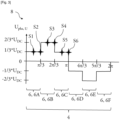
- a voltage U pha,U of the first phase of the three-phase inverter is monitored during a fundamental period 4 which corresponds to 2 ⁇ .
- the fundamental period 4 is divided into subperiods or time periods 6; more precisely, the fundamental period 4 is divided into six time periods 6 of equal lengths, here six time periods 6 of ⁇ /3.
- the inverter carries out a maximum of six switching actions during the fundamental period 4, which equates to only one switching action during the course of each time period 6. As such, a closed switch of a given phase of the inverter goes from being "on" to being opened or "off”, and an opened switch of said phase goes from being “off” to closed or "on” just once per time period 6.
- the top switch of the first phase is operated to be closed and the bottom switch of this first phase is operated to be opened so that the first phase is in a + state; the top switch of the second phase is operated to be opened and the bottom switch of this second phase is operated to be closed so that the second phase is in a - state; and the top switch of the third phase is operated to be closed and the bottom switch of this first phase is operated to be opened so that the third phase is in a + state.
- the voltage U pha,U for the first phase is equal to Uoc/3
- the voltage transmitted on the second phase is -2/3*U DC
- the voltage of the third phase equals U DC /3
- U DC being the input direct current voltage of the three-phase inverter.
- first switch of the third period is opened and the second switch of this third phase is closed.
- the voltage for the first phase is now 2/3*UDC, and the inverter is in a +-- state.
- a third time period 6C occurring from 2 ⁇ /3 to ⁇
- the top switch of the second phase of the inverter is closed and its bottom switch is opened, so that the inverter is in a ++- state.
- a fourth time period 6D occurring from ⁇ to 4 ⁇ /3
- the first switch of the first phase of the inverter is closed and its second switch is opened, resulting in the inverter being in a -+- state.
- n-1 and 6n+1 voltage harmonics appear, with a significant harmonic content of 6n-1 and 6n+1, with n being an integer.
- a 5 th harmonic and a 7 th harmonic appear as a 6 th harmonic in rotating coordinates
- a 11 th harmonic and a 13 th harmonic appear as a 12 th harmonic in rotating coordinates.
- the AC acquisition method solves this unwanted harmonic problem with a sampling step 8 in which a plurality of AC values of the inverter are sampled from each time period 6 of the fundamental period 4. In other words, there is a plurality of sampled values S for each time period 6.
- the AC values are more precisely sampled from a first reference frame of the inverter, and these AC values are sampled at equidistant intervals within a given time period 6.
- the sampling step 8 is carried out using any current sensing method.
- the sampled values S can be extracted using single-shot methods, 2-phase current sensor methods or 3-phase current sensor methods.
- the plurality of AC values which are sampled within a given time period 6 corresponds to two values.
- Only the sampled values for the first time period 6A to the third time period 6C are represented on Figure 3 , but it is understood that the sampling occurs accordingly in the fourth, fifth and sixth time periods 6D, 6E, 6F.
- the sampled values S are taken at equidistant intervals, each value is here sampled at a ⁇ /6 interval.
- one of the two sampled values S is sampled at the time at which a switching action of the inverter occurs, i.e. at the end of a given time period 6.
- the second sampled values S2, S4 and S6 for each time period 6 are extracted when the inverter goes from being “on” to being “off” or conversely from being “off” to being “on”.
- the first sampled values S1, S3, S5 for each time period 6 are extracted in the absence of a switching action, more precisely in the middle of a given time period 6.
- the number of sampled values S per time period 6 of the fundamental period 4 depends on the embodiment.
- the plurality of AC values which are sampled within a given time period 6 corresponds to four values.
- each value is sampled at a ⁇ /12 interval.
- the AC acquisition method 1 comprises a rotating step 10.
- This rotating step 10 consists in a change of reference frame.
- the first reference frame in which the sampled values S were extracted is transformed into a second reference frame.
- the reference frame change is the result of a rotation.
- a Park transformation is used to rotate each sampled value S from the first reference frame to the second reference frame.
- the Park transformation used to rotate the sampled values S from the first reference frame to the second reference frame is function of an angle of the electric machine.
- the angle of the electric machine, or transformation angle rotates with the fundamental angular frequency. It is for instance aligned with a flux of a rotor of the electric machine.
- the angle of the electric machine is detected by any angle sensing technology.
- averaging step 12 corresponds to the application of an average filter to the sampled values S in the second reference frame.
- the sampled values are averaged after they have undergone the Park transformation.
- the sampled values are more precisely averaged within each time period 6 separately. For instance, in the first embodiment of Figure 1 the average filter is applied to the two sampled values S1, S2 of the first time period 6A, then the average filter is applied to the two sampled values S3, S4 of the second time period 6B, and so on until the sixth time period 6E of the fundamental period 4.
- a higher number of sampled values S per time period 6 leads to a higher number of unwanted harmonics being suppressed.
- the number of suppressed unwanted harmonics is higher in the second embodiment compared to in the first embodiment.
- 6n-1 harmonics and 6n+1 harmonics appear as 6n harmonics.
- the 5 th harmonic and the 7 th harmonic appear as the 6 th harmonic
- the 11 th harmonic and the 13 th harmonic appear as the 12 th harmonic, etc.
- the averaging step 12 applied to the two sampled values S extracted from each time period 6 during the sampling step 8 results in the disappearance of the 6 th harmonic, a 18 th harmonic, a 30 th harmonic and other higher harmonics.
- the 6 th harmonic, the 12 th harmonic, the 18 th harmonic and other higher harmonics are suppressed.
- the AC acquisition method 1 ends with a final estimation step 14, during which a current value is estimated according to the previously averaged sampled values S.
- the present invention thus covers an alternating current acquisition method in which a number of sample values is increased in order to average them, eliminating noise in the form of unwanted harmonics in the signal by doing so and thus providing a more accurate acquisition.
Landscapes
- Engineering & Computer Science (AREA)
- Power Engineering (AREA)
- Physics & Mathematics (AREA)
- General Physics & Mathematics (AREA)
- Transportation (AREA)
- Mechanical Engineering (AREA)
- Inverter Devices (AREA)
Priority Applications (3)
| Application Number | Priority Date | Filing Date | Title |
|---|---|---|---|
| EP23188241.6A EP4498098A1 (de) | 2023-07-27 | 2023-07-27 | Wechselstromerfassungsverfahren |
| CN202411014536.9A CN119375530A (zh) | 2023-07-27 | 2024-07-26 | Ac电流采集方法 |
| US18/786,197 US20250035681A1 (en) | 2023-07-27 | 2024-07-26 | Ac current acquisition method |
Applications Claiming Priority (1)
| Application Number | Priority Date | Filing Date | Title |
|---|---|---|---|
| EP23188241.6A EP4498098A1 (de) | 2023-07-27 | 2023-07-27 | Wechselstromerfassungsverfahren |
Publications (1)
| Publication Number | Publication Date |
|---|---|
| EP4498098A1 true EP4498098A1 (de) | 2025-01-29 |
Family
ID=87517469
Family Applications (1)
| Application Number | Title | Priority Date | Filing Date |
|---|---|---|---|
| EP23188241.6A Pending EP4498098A1 (de) | 2023-07-27 | 2023-07-27 | Wechselstromerfassungsverfahren |
Country Status (3)
| Country | Link |
|---|---|
| US (1) | US20250035681A1 (de) |
| EP (1) | EP4498098A1 (de) |
| CN (1) | CN119375530A (de) |
Citations (3)
| Publication number | Priority date | Publication date | Assignee | Title |
|---|---|---|---|---|
| US20110080125A1 (en) * | 2009-10-02 | 2011-04-07 | Aisin Aw Co., Ltd. | Control device for electric motor drive apparatus |
| US20180309399A1 (en) * | 2017-04-21 | 2018-10-25 | Mitsubishi Electric Corporation | Control device for an electric motor |
| EP3654524A1 (de) * | 2018-11-14 | 2020-05-20 | Bayerische Motoren Werke Aktiengesellschaft | Verfahren und steuereinheit zum betrieb eines elektromotors |
Family Cites Families (6)
| Publication number | Priority date | Publication date | Assignee | Title |
|---|---|---|---|---|
| US6768284B2 (en) * | 2002-09-30 | 2004-07-27 | Eaton Corporation | Method and compensation modulator for dynamically controlling induction machine regenerating energy flow and direct current bus voltage for an adjustable frequency drive system |
| US7834574B2 (en) * | 2007-11-26 | 2010-11-16 | Gm Global Technology Operations, Inc. | Phase current sampling and regulating apparatus and methods, and electric motor drive systems |
| DE102016203273A1 (de) * | 2016-02-29 | 2017-08-31 | Zf Friedrichshafen Ag | Verfahren und Anordnung zur Überwachung eines Rotorpositionssensors einer PSM-Maschine |
| US10236808B2 (en) * | 2016-08-25 | 2019-03-19 | Analog Devices, Inc. | Systems and methods for determining motor parameters |
| EP3477314B1 (de) * | 2017-10-24 | 2020-09-30 | Mitsubishi Electric R & D Centre Europe B.V. | Verfahren zur online-überwachung eines zwischenkreis-kondensators |
| EP3902135B1 (de) * | 2020-04-20 | 2023-12-13 | ABB Schweiz AG | Winkelpositionsfehlerschätzung im stillstand für hochfrequenzspannungsinjektion |
-
2023
- 2023-07-27 EP EP23188241.6A patent/EP4498098A1/de active Pending
-
2024
- 2024-07-26 CN CN202411014536.9A patent/CN119375530A/zh active Pending
- 2024-07-26 US US18/786,197 patent/US20250035681A1/en active Pending
Patent Citations (3)
| Publication number | Priority date | Publication date | Assignee | Title |
|---|---|---|---|---|
| US20110080125A1 (en) * | 2009-10-02 | 2011-04-07 | Aisin Aw Co., Ltd. | Control device for electric motor drive apparatus |
| US20180309399A1 (en) * | 2017-04-21 | 2018-10-25 | Mitsubishi Electric Corporation | Control device for an electric motor |
| EP3654524A1 (de) * | 2018-11-14 | 2020-05-20 | Bayerische Motoren Werke Aktiengesellschaft | Verfahren und steuereinheit zum betrieb eines elektromotors |
Also Published As
| Publication number | Publication date |
|---|---|
| US20250035681A1 (en) | 2025-01-30 |
| CN119375530A (zh) | 2025-01-28 |
Similar Documents
| Publication | Publication Date | Title |
|---|---|---|
| JP6132948B1 (ja) | モータ制御装置およびモータ制御方法 | |
| Lu et al. | Pulsating high frequency voltage injection strategy for sensorless permanent magnet synchronous motor drives | |
| EP2180589A2 (de) | Verfahren zur Vorhersage von Phasenstrom | |
| JP6316481B1 (ja) | 電動機の制御装置 | |
| Dusmez et al. | A new SVPWM technique for DC negative rail current sensing at low speeds | |
| JP6116538B2 (ja) | モータ制御装置 | |
| Weber et al. | Increased signal-to-noise ratio of sensorless control using current oversampling | |
| Chen et al. | Fundamental PWM excitation based rotor position estimation for a dual three-phase permanent magnet synchronous machine | |
| Ma et al. | System-on-Chip sensorless control of PMSM combining signal injection and flux observer | |
| EP4498098A1 (de) | Wechselstromerfassungsverfahren | |
| US11031899B1 (en) | Method for operating an electronically commutated synchronous machine, and actuation circuit | |
| JP2017022909A (ja) | 電流センサ異常診断装置 | |
| Bossoufi et al. | Performance analysis of direct torque control (DTC) for synchronous machine permanent magnet (PMSM) | |
| Ma et al. | FPGA based signal injection sensorless control of SMPMSM using Delta-Sigma A/D conversion | |
| US20060261773A1 (en) | Method, system, and program product for feedback control of a target system utilizing imposition of a periodic modulating signal onto a command signal | |
| EP3930169A1 (de) | Leistungsumwandlungsvorrichtung und elektrische servolenkvorrichtung | |
| JP6750364B2 (ja) | 回転電機の回転角推定装置 | |
| Chou et al. | Sensorless control of PMSG based on dual two-level inverter open winding configuration for wind turbines | |
| JPH0260493A (ja) | 直流ブラシレスモータ | |
| JP2019037101A (ja) | 回転電機の制御装置 | |
| Su et al. | Model predictive torque-vector control for four-switch three-phase inverter-fed PMSM with capacitor voltage offset suppression | |
| Al-Badrani | Flux Observation of Induction Machine Based on the Enhanced Sensorless Voltage Model | |
| Piippo et al. | Sensorless PMSM drive with DC-link current measurement | |
| Yang | Initial rotor position estimation of permanent magnet synchronous machines using square-wave voltage injection with a single current sensor | |
| Miura et al. | A rotor position estimation of SR motor based on complex plane expression of phase inductance |
Legal Events
| Date | Code | Title | Description |
|---|---|---|---|
| PUAI | Public reference made under article 153(3) epc to a published international application that has entered the european phase |
Free format text: ORIGINAL CODE: 0009012 |
|
| STAA | Information on the status of an ep patent application or granted ep patent |
Free format text: STATUS: THE APPLICATION HAS BEEN PUBLISHED |
|
| AK | Designated contracting states |
Kind code of ref document: A1 Designated state(s): AL AT BE BG CH CY CZ DE DK EE ES FI FR GB GR HR HU IE IS IT LI LT LU LV MC ME MK MT NL NO PL PT RO RS SE SI SK SM TR |
|
| STAA | Information on the status of an ep patent application or granted ep patent |
Free format text: STATUS: REQUEST FOR EXAMINATION WAS MADE |
|
| 17P | Request for examination filed |
Effective date: 20250724 |