EP4497848A1 - Elektrolytmembran, elektrolytmembran mit katalysatorschicht, membranelektrodenanordnung und wasserelektrolysevorrichtung - Google Patents
Elektrolytmembran, elektrolytmembran mit katalysatorschicht, membranelektrodenanordnung und wasserelektrolysevorrichtung Download PDFInfo
- Publication number
- EP4497848A1 EP4497848A1 EP23774589.8A EP23774589A EP4497848A1 EP 4497848 A1 EP4497848 A1 EP 4497848A1 EP 23774589 A EP23774589 A EP 23774589A EP 4497848 A1 EP4497848 A1 EP 4497848A1
- Authority
- EP
- European Patent Office
- Prior art keywords
- electrolyte
- electrolyte layer
- layer
- membrane
- polymer
- Prior art date
- Legal status (The legal status is an assumption and is not a legal conclusion. Google has not performed a legal analysis and makes no representation as to the accuracy of the status listed.)
- Pending
Links
Images
Classifications
-
- H—ELECTRICITY
- H01—ELECTRIC ELEMENTS
- H01M—PROCESSES OR MEANS, e.g. BATTERIES, FOR THE DIRECT CONVERSION OF CHEMICAL ENERGY INTO ELECTRICAL ENERGY
- H01M8/00—Fuel cells; Manufacture thereof
- H01M8/10—Fuel cells with solid electrolytes
- H01M8/1016—Fuel cells with solid electrolytes characterised by the electrolyte material
- H01M8/1018—Polymeric electrolyte materials
- H01M8/1039—Polymeric electrolyte materials halogenated, e.g. sulfonated polyvinylidene fluorides
-
- C—CHEMISTRY; METALLURGY
- C25—ELECTROLYTIC OR ELECTROPHORETIC PROCESSES; APPARATUS THEREFOR
- C25B—ELECTROLYTIC OR ELECTROPHORETIC PROCESSES FOR THE PRODUCTION OF COMPOUNDS OR NON-METALS; APPARATUS THEREFOR
- C25B13/00—Diaphragms; Spacing elements
- C25B13/04—Diaphragms; Spacing elements characterised by the material
-
- C—CHEMISTRY; METALLURGY
- C25—ELECTROLYTIC OR ELECTROPHORETIC PROCESSES; APPARATUS THEREFOR
- C25B—ELECTROLYTIC OR ELECTROPHORETIC PROCESSES FOR THE PRODUCTION OF COMPOUNDS OR NON-METALS; APPARATUS THEREFOR
- C25B13/00—Diaphragms; Spacing elements
- C25B13/02—Diaphragms; Spacing elements characterised by shape or form
-
- C—CHEMISTRY; METALLURGY
- C25—ELECTROLYTIC OR ELECTROPHORETIC PROCESSES; APPARATUS THEREFOR
- C25B—ELECTROLYTIC OR ELECTROPHORETIC PROCESSES FOR THE PRODUCTION OF COMPOUNDS OR NON-METALS; APPARATUS THEREFOR
- C25B1/00—Electrolytic production of inorganic compounds or non-metals
- C25B1/01—Products
- C25B1/02—Hydrogen or oxygen
- C25B1/04—Hydrogen or oxygen by electrolysis of water
-
- C—CHEMISTRY; METALLURGY
- C25—ELECTROLYTIC OR ELECTROPHORETIC PROCESSES; APPARATUS THEREFOR
- C25B—ELECTROLYTIC OR ELECTROPHORETIC PROCESSES FOR THE PRODUCTION OF COMPOUNDS OR NON-METALS; APPARATUS THEREFOR
- C25B11/00—Electrodes; Manufacture thereof not otherwise provided for
- C25B11/04—Electrodes; Manufacture thereof not otherwise provided for characterised by the material
- C25B11/051—Electrodes formed of electrocatalysts on a substrate or carrier
- C25B11/052—Electrodes comprising one or more electrocatalytic coatings on a substrate
- C25B11/053—Electrodes comprising one or more electrocatalytic coatings on a substrate characterised by multilayer electrocatalytic coatings
-
- C—CHEMISTRY; METALLURGY
- C25—ELECTROLYTIC OR ELECTROPHORETIC PROCESSES; APPARATUS THEREFOR
- C25B—ELECTROLYTIC OR ELECTROPHORETIC PROCESSES FOR THE PRODUCTION OF COMPOUNDS OR NON-METALS; APPARATUS THEREFOR
- C25B11/00—Electrodes; Manufacture thereof not otherwise provided for
- C25B11/04—Electrodes; Manufacture thereof not otherwise provided for characterised by the material
- C25B11/051—Electrodes formed of electrocatalysts on a substrate or carrier
- C25B11/054—Electrodes comprising electrocatalysts supported on a carrier
-
- C—CHEMISTRY; METALLURGY
- C25—ELECTROLYTIC OR ELECTROPHORETIC PROCESSES; APPARATUS THEREFOR
- C25B—ELECTROLYTIC OR ELECTROPHORETIC PROCESSES FOR THE PRODUCTION OF COMPOUNDS OR NON-METALS; APPARATUS THEREFOR
- C25B11/00—Electrodes; Manufacture thereof not otherwise provided for
- C25B11/04—Electrodes; Manufacture thereof not otherwise provided for characterised by the material
- C25B11/051—Electrodes formed of electrocatalysts on a substrate or carrier
- C25B11/055—Electrodes formed of electrocatalysts on a substrate or carrier characterised by the substrate or carrier material
- C25B11/057—Electrodes formed of electrocatalysts on a substrate or carrier characterised by the substrate or carrier material consisting of a single element or compound
- C25B11/065—Carbon
-
- C—CHEMISTRY; METALLURGY
- C25—ELECTROLYTIC OR ELECTROPHORETIC PROCESSES; APPARATUS THEREFOR
- C25B—ELECTROLYTIC OR ELECTROPHORETIC PROCESSES FOR THE PRODUCTION OF COMPOUNDS OR NON-METALS; APPARATUS THEREFOR
- C25B11/00—Electrodes; Manufacture thereof not otherwise provided for
- C25B11/04—Electrodes; Manufacture thereof not otherwise provided for characterised by the material
- C25B11/051—Electrodes formed of electrocatalysts on a substrate or carrier
- C25B11/073—Electrodes formed of electrocatalysts on a substrate or carrier characterised by the electrocatalyst material
- C25B11/075—Electrodes formed of electrocatalysts on a substrate or carrier characterised by the electrocatalyst material consisting of a single catalytic element or catalytic compound
- C25B11/081—Electrodes formed of electrocatalysts on a substrate or carrier characterised by the electrocatalyst material consisting of a single catalytic element or catalytic compound the element being a noble metal
-
- C—CHEMISTRY; METALLURGY
- C25—ELECTROLYTIC OR ELECTROPHORETIC PROCESSES; APPARATUS THEREFOR
- C25B—ELECTROLYTIC OR ELECTROPHORETIC PROCESSES FOR THE PRODUCTION OF COMPOUNDS OR NON-METALS; APPARATUS THEREFOR
- C25B13/00—Diaphragms; Spacing elements
- C25B13/04—Diaphragms; Spacing elements characterised by the material
- C25B13/05—Diaphragms; Spacing elements characterised by the material based on inorganic materials
-
- C—CHEMISTRY; METALLURGY
- C25—ELECTROLYTIC OR ELECTROPHORETIC PROCESSES; APPARATUS THEREFOR
- C25B—ELECTROLYTIC OR ELECTROPHORETIC PROCESSES FOR THE PRODUCTION OF COMPOUNDS OR NON-METALS; APPARATUS THEREFOR
- C25B13/00—Diaphragms; Spacing elements
- C25B13/04—Diaphragms; Spacing elements characterised by the material
- C25B13/08—Diaphragms; Spacing elements characterised by the material based on organic materials
-
- C—CHEMISTRY; METALLURGY
- C25—ELECTROLYTIC OR ELECTROPHORETIC PROCESSES; APPARATUS THEREFOR
- C25B—ELECTROLYTIC OR ELECTROPHORETIC PROCESSES FOR THE PRODUCTION OF COMPOUNDS OR NON-METALS; APPARATUS THEREFOR
- C25B9/00—Cells or assemblies of cells; Constructional parts of cells; Assemblies of constructional parts, e.g. electrode-diaphragm assemblies; Process-related cell features
- C25B9/17—Cells comprising dimensionally-stable non-movable electrodes; Assemblies of constructional parts thereof
- C25B9/19—Cells comprising dimensionally-stable non-movable electrodes; Assemblies of constructional parts thereof with diaphragms
- C25B9/23—Cells comprising dimensionally-stable non-movable electrodes; Assemblies of constructional parts thereof with diaphragms comprising ion-exchange membranes in or on which electrode material is embedded
-
- H—ELECTRICITY
- H01—ELECTRIC ELEMENTS
- H01B—CABLES; CONDUCTORS; INSULATORS; SELECTION OF MATERIALS FOR THEIR CONDUCTIVE, INSULATING OR DIELECTRIC PROPERTIES
- H01B1/00—Conductors or conductive bodies characterised by the conductive materials; Selection of materials as conductors
- H01B1/06—Conductors or conductive bodies characterised by the conductive materials; Selection of materials as conductors mainly consisting of other non-metallic substances
-
- H—ELECTRICITY
- H01—ELECTRIC ELEMENTS
- H01M—PROCESSES OR MEANS, e.g. BATTERIES, FOR THE DIRECT CONVERSION OF CHEMICAL ENERGY INTO ELECTRICAL ENERGY
- H01M8/00—Fuel cells; Manufacture thereof
- H01M8/10—Fuel cells with solid electrolytes
-
- H—ELECTRICITY
- H01—ELECTRIC ELEMENTS
- H01M—PROCESSES OR MEANS, e.g. BATTERIES, FOR THE DIRECT CONVERSION OF CHEMICAL ENERGY INTO ELECTRICAL ENERGY
- H01M8/00—Fuel cells; Manufacture thereof
- H01M8/10—Fuel cells with solid electrolytes
- H01M8/1004—Fuel cells with solid electrolytes characterised by membrane-electrode assemblies [MEA]
-
- H—ELECTRICITY
- H01—ELECTRIC ELEMENTS
- H01M—PROCESSES OR MEANS, e.g. BATTERIES, FOR THE DIRECT CONVERSION OF CHEMICAL ENERGY INTO ELECTRICAL ENERGY
- H01M8/00—Fuel cells; Manufacture thereof
- H01M8/10—Fuel cells with solid electrolytes
- H01M8/1016—Fuel cells with solid electrolytes characterised by the electrolyte material
- H01M8/1018—Polymeric electrolyte materials
- H01M8/1041—Polymer electrolyte composites, mixtures or blends
- H01M8/1046—Mixtures of at least one polymer and at least one additive
- H01M8/1051—Non-ion-conducting additives, e.g. stabilisers, SiO2 or ZrO2
-
- H—ELECTRICITY
- H01—ELECTRIC ELEMENTS
- H01M—PROCESSES OR MEANS, e.g. BATTERIES, FOR THE DIRECT CONVERSION OF CHEMICAL ENERGY INTO ELECTRICAL ENERGY
- H01M8/00—Fuel cells; Manufacture thereof
- H01M8/10—Fuel cells with solid electrolytes
- H01M8/1016—Fuel cells with solid electrolytes characterised by the electrolyte material
- H01M8/1018—Polymeric electrolyte materials
- H01M8/1041—Polymer electrolyte composites, mixtures or blends
- H01M8/1053—Polymer electrolyte composites, mixtures or blends consisting of layers of polymers with at least one layer being ionically conductive
-
- H—ELECTRICITY
- H01—ELECTRIC ELEMENTS
- H01M—PROCESSES OR MEANS, e.g. BATTERIES, FOR THE DIRECT CONVERSION OF CHEMICAL ENERGY INTO ELECTRICAL ENERGY
- H01M8/00—Fuel cells; Manufacture thereof
- H01M8/10—Fuel cells with solid electrolytes
- H01M8/1016—Fuel cells with solid electrolytes characterised by the electrolyte material
- H01M8/1018—Polymeric electrolyte materials
- H01M8/1058—Polymeric electrolyte materials characterised by a porous support having no ion-conducting properties
-
- H—ELECTRICITY
- H01—ELECTRIC ELEMENTS
- H01M—PROCESSES OR MEANS, e.g. BATTERIES, FOR THE DIRECT CONVERSION OF CHEMICAL ENERGY INTO ELECTRICAL ENERGY
- H01M8/00—Fuel cells; Manufacture thereof
- H01M8/10—Fuel cells with solid electrolytes
- H01M8/1016—Fuel cells with solid electrolytes characterised by the electrolyte material
- H01M8/1018—Polymeric electrolyte materials
- H01M8/1067—Polymeric electrolyte materials characterised by their physical properties, e.g. porosity, ionic conductivity or thickness
-
- H—ELECTRICITY
- H01—ELECTRIC ELEMENTS
- H01M—PROCESSES OR MEANS, e.g. BATTERIES, FOR THE DIRECT CONVERSION OF CHEMICAL ENERGY INTO ELECTRICAL ENERGY
- H01M8/00—Fuel cells; Manufacture thereof
- H01M8/10—Fuel cells with solid electrolytes
- H01M2008/1095—Fuel cells with polymeric electrolytes
-
- Y—GENERAL TAGGING OF NEW TECHNOLOGICAL DEVELOPMENTS; GENERAL TAGGING OF CROSS-SECTIONAL TECHNOLOGIES SPANNING OVER SEVERAL SECTIONS OF THE IPC; TECHNICAL SUBJECTS COVERED BY FORMER USPC CROSS-REFERENCE ART COLLECTIONS [XRACs] AND DIGESTS
- Y02—TECHNOLOGIES OR APPLICATIONS FOR MITIGATION OR ADAPTATION AGAINST CLIMATE CHANGE
- Y02E—REDUCTION OF GREENHOUSE GAS [GHG] EMISSIONS, RELATED TO ENERGY GENERATION, TRANSMISSION OR DISTRIBUTION
- Y02E60/00—Enabling technologies; Technologies with a potential or indirect contribution to GHG emissions mitigation
- Y02E60/30—Hydrogen technology
- Y02E60/36—Hydrogen production from non-carbon containing sources, e.g. by water electrolysis
-
- Y—GENERAL TAGGING OF NEW TECHNOLOGICAL DEVELOPMENTS; GENERAL TAGGING OF CROSS-SECTIONAL TECHNOLOGIES SPANNING OVER SEVERAL SECTIONS OF THE IPC; TECHNICAL SUBJECTS COVERED BY FORMER USPC CROSS-REFERENCE ART COLLECTIONS [XRACs] AND DIGESTS
- Y02—TECHNOLOGIES OR APPLICATIONS FOR MITIGATION OR ADAPTATION AGAINST CLIMATE CHANGE
- Y02E—REDUCTION OF GREENHOUSE GAS [GHG] EMISSIONS, RELATED TO ENERGY GENERATION, TRANSMISSION OR DISTRIBUTION
- Y02E60/00—Enabling technologies; Technologies with a potential or indirect contribution to GHG emissions mitigation
- Y02E60/30—Hydrogen technology
- Y02E60/50—Fuel cells
Definitions
- the present invention relates to an electrolyte membrane, a catalyst coated membrane, a membrane electrode assembly, and a water electrolyzer.
- Hydrogen energy is drawing attention in recent years, as means for energy storage and transportation of the next generation.
- hydrogen can be converted to electric power at an energy efficiency theoretically higher than that of power generation using a heat engine, and also produces no harmful emissions. Therefore, hydrogen can be a highly efficient clean energy source.
- Electrolysis of water is known as one of hydrogen production methods.
- the electrolysis of water using surplus electricity generated by renewable energy enables to convert electric power to hydrogen energy without carbon dioxide emissions. Further, since hydrogen can be transported by a tanker truck or a tanker depending on the storage method, and can be supplied whenever to wherever needed, the electrolysis of water has a high potential as a tool for storing electric power.
- Examples of the hydrogen production method by the electrolysis of water include alkaline water electrolysis and polymer electrolyte membrane water electrolysis.
- the polymer electrolyte membrane water electrolysis can be operated at a high current density, and has the advantage that it is capable of flexibly responding to output fluctuations of renewable energy.
- a fluoropolymer electrolyte such as perfluorinated sulfonic acid has been conventionally and commonly known as a polymer electrolyte contained in an electrolyte membrane.
- a hydrocarbon-based polymer electrolyte instead of the fluoropolymer electrolyte, has been examined, from the viewpoints of material cost and the like (see Patent Literature 1, for example).
- Patent Literature 1 JP 2005-133146 A
- an object of the present invention is to provide an electrolyte membrane having a good durability.
- the present inventors found out that the above-described problem is due to the facts that polymer electrolytes are susceptible to degradation by the attack of hydrogen peroxide and hydrogen peroxide radicals, and that, in a water electrolyzer, hydrogen peroxide and hydrogen peroxide radicals are generated at the cathode, and this creates an environment in which the electrolyte membrane is susceptible to the attack, thereby completing the present invention.
- an electrolyte membrane including:
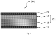
- FIG. 1 is a cross-sectional schematic diagram of one embodiment of the catalyst coated membrane according to the present invention.
- the electrolyte membrane according to an embodiment of the present invention includes: a first electrolyte layer having a thickness of 40 ⁇ m or more and 250 ⁇ m or less and containing a polymer electrolyte; and a second electrolyte layer provided on the first main surface of the first electrolyte layer and containing a polymer electrolyte and carbon particles.
- the first electrolyte layer is a layer that provides an inherent function (such as proton conduction) of the electrolyte membrane, and the second electrolyte layer has a function of protecting the first electrolyte layer. That is, the first electrolyte layer functions as a polymer electrolyte layer, and the second electrolyte layer functions as a protective layer of the first electrolyte layer. Detailed description will be given below.
- hydrogen peroxide and hydrogen peroxide radicals are collectively referred to as "hydrogen peroxides”.
- the generation of hydrogen peroxides at the cathode is due to the transfer of oxygen generated at the anode to the cathode, as described above, it is effective to increase the thickness of the electrolyte membrane from the viewpoint of reducing the transfer of oxygen. That is, when the first electrolyte layer has a thickness of 40 ⁇ m or more, the oxygen permeability is decreased, and as a result, the effect of reducing the generation of hydrogen peroxides at the cathode can be expected. Further, having a thickness of the first electrolyte layer of 40 ⁇ m or more is effective also from the viewpoint of the durability.
- the first electrolyte layer has a thickness of 40 ⁇ m or more and 250 ⁇ m or less.
- the thickness of the first electrolyte layer is preferably 50 ⁇ m or more, more preferably 60 ⁇ m or more, and particularly preferably 70 ⁇ m or more, from the viewpoint of improving the durability.
- the first electrolyte layer has a thickness of more than 250 ⁇ m, on the other hand, it leads to a decrease in water electrolysis performance, and it is disadvantageous from the viewpoints of material cost, productivity and workability.
- the thickness of the first electrolyte layer is preferably 200 ⁇ m or less, more preferably 180 ⁇ m or less, and still more preferably 150 ⁇ m or less.
- the first electrolyte layer contains a polymer electrolyte.
- the polymer electrolyte is not particularly limited, and it is possible to use any polymer electrolyte known in the art.
- polymer electrolytes are broadly classified into fluoropolymer electrolytes and hydrocarbon-based polymer electrolytes, and either type of electrolyte can be used in the present invention.
- fluoropolymer electrolyte refers to a fluoropolymer containing an ionic group.
- fluoropolymer refers to a polymer in which most or all of hydrogen atoms in the alkyl groups and/or alkylene groups in the molecule are substituted with fluorine atoms.
- fluoropolymer electrolyte examples include perfluorinated sulfonic acid-based polymers, perfluorinated phosphonic acid-based polymers, trifluorostyrene sulfonic acid-based polymers, trifluorostyrene phosphonic acid-based polymers, ethylene tetrafluoroethylene-g-styrene sulfonic acid-based polymers, ethylene-tetrafluoroethylene copolymers, and polyvinylidene fluorideperfluorinated sulfonic acid-based polymers.
- a perfluorinated sulfonic acid-based polymer is preferred from the viewpoints of heat resistance and chemical stability.
- examples of such a polymer include commercially available products such as "Nafion” (registered trademark) (manufactured by The Chemours Company TT, LLC), “FLEMION” (registered trademark) (manufactured by AGC Chemicals Company) and “Asiplex” (registered trademark) (manufactured by Asahi Kasei Corporation).
- hydrocarbon-based polymer electrolytes are suitable as a polymer electrolyte to be used, because of their good water electrolysis performance and gas barrier properties, and relatively low material cost.
- hydrocarbon-based polymer electrolytes tend to be susceptible to degradation by the attack of hydrogen peroxides, as compared to fluoropolymer electrolytes.
- the use of such a hydrocarbon-based polymer electrolyte allows for improving the durability, which is a problem to be solved, while making use of its advantages, such as good water electrolysis performance.
- hydrocarbon-based polymer electrolytes have the characteristic that the permeability of gas such as oxygen is lower as compared to that of fluoropolymer electrolytes. Therefore, when the first electrolyte layer containing a hydrocarbon-based polymer electrolyte has a thickness of 40 ⁇ m or more, the oxygen permeability is further decreased, and the effect of reducing the generation of hydrogen peroxides at the cathode is expected.
- the electrolyte membrane according to the present invention preferably has an oxygen permeability, in an atmosphere of a temperature of 80°C and a relative humidity 90%, of 2.0 ⁇ 10 -8 cm 3 (cm 2 ⁇ s ⁇ cmHg) -1 or less, more preferably 1.0 ⁇ 10 -8 cm 3 (cm 2 ⁇ s ⁇ cmHg) -1 or less, and particularly preferably 0.7 ⁇ 10 -8 cm 3 (cm 2 ⁇ s ⁇ cmHg) -1 or less. While the lower limit thereof is not particularly limited, the oxygen permeability is preferably 1.0 ⁇ 10 -11 cm 3 (cm 2 ⁇ s ⁇ cmHg) -1 or more.
- hydrocarbon-based polymer electrolyte refers to a hydrocarbon-based polymer containing an ionic group.
- the "hydrocarbon-based polymer containing an ionic group” refers to a polymer having a main chain containing a hydrocarbon as a main structural unit and containing an ionic group added to the main chain or a side chain, in which polymer the main chain or the side chain is not substantially fluorinated.
- the expression “not substantially fluorinated” as used herein is not intended to exclude a polymer having a fluorinated portion in a very small portion of the main chain or the side chain.
- the definition of the hydrocarbon-based polymer containing an ionic group includes a hydrocarbon-based polymer in which the content of fluorine atoms is less than 5% by mass per number average molecular weight of the polymer.
- the hydrocarbon-based polymer electrolyte is preferably an aromatic hydrocarbon-based polymer having an aromatic ring in the main chain.
- the definition of the aromatic ring may include not only a hydrocarbon-based aromatic ring, but also a heterocyclic ring. Further, the polymer may partially contain an aliphatic-based unit along with an aromatic ring unit.
- aromatic hydrocarbon-based polymer examples include polymers having, in the main chain, a structure selected from the group consisting of: polysulfone, polyether sulfone, polyphenylene oxide, polyarylene ether, polyphenylene sulfide, polyphenylene sulfide sulfone, polyparaphenylene, a polyarylene-based polymer, polyarylene ketone, polyether ketone, polyarylene phosphine oxide, polyether phosphine oxide, polybenzoxazole, polybenzothiazole, polybenzimidazole, polyamide, polyimide, polyetherimide and polyimidesulfone, along with the aromatic ring.
- polysulfone as described above is a generic term for a structure having a sulfone bond in the molecular chain
- polyether sulfone is a generic term for a structure having an ether bond and a sulfone bond in the molecular chain
- polyether ketone is a generic term for a structure having an ether bond and a ketone bond in the molecular chain.
- the aromatic hydrocarbon-based polymer may have a plurality of structures among these structures.
- a polyether ketone-based polymer is particularly preferred as the aromatic hydrocarbon-based polymer.
- the polyether ketone-based polymer include polyether ketone, polyether ketone ketone, polyether ether ketone, polyether ether ketone ketone and polyether ketone ether ketone ketone.
- the polyether ketone-based polymer has a relatively low oxygen permeability, and thus is suitable as a hydrocarbon-based electrolyte in the first electrolyte layer.
- the hydrocarbon-based polymer electrolyte is preferably a block copolymer having one or more of each of a segment containing an ionic group (ionic segment) and a segment containing no ionic group (non-ionic segment).
- the "segment” as used herein refers to a partial structure in the polymer chain of a copolymer composed of repeating units showing specific properties (for example, ionic or non-ionic properties), which structure has a molecular weight of 2,000 or more.
- the non-ionic segment may contain a small amount of ionic groups as long as the effects of the present invention are not adversely affected.
- the block copolymer has a better water electrolysis performance as compared to that of a random copolymer. Therefore, in cases where the electrolyte membrane according to the present invention is used in a water electrolyzer, it is preferred to use the block copolymer as the hydrocarbon-based polymer electrolyte in the first electrolyte layer.
- the ionic group to be contained in the hydrocarbon-based polymer electrolyte can be any ionic group having either a cation exchange capacity or an anion exchange capacity.
- a functional group a sulfonic acid group, a sulfonimide group, a sulfuric acid group, a phosphonic acid group, a phosphoric acid group, a carboxylic acid group, an ammonium group, a phosphonium group, an amino group, an imidazolium group or the like is preferably used.
- the polymer can contain two or more types of ionic groups.
- the polymer more preferably contains at least one selected from the group consisting of a sulfonic acid group, a sulfonimide group and a sulfuric acid group, from the viewpoint of obtaining an excellent water electrolysis performance, and most preferably contains a sulfonic acid group, from the viewpoint of the raw material cost.
- the hydrocarbon-based polymer electrolyte preferably has an ion exchange capacity (IEC) of 0.1 meq/g or more and 5.0 meq/g or less, from the viewpoint of the balance between proton conductivity and water resistance.
- IEC ion exchange capacity
- the IEC is more preferably 1.0 meq/g or more, and still more preferably 1.4 meq/g or more. Further, the IEC is more preferably 3.5 meq/g or less, and still more preferably 3.0 meq/g or less.
- the "IEC" as used herein refers to the molar amount of ionic groups introduced into the hydrocarbon-based polymer electrolyte per unit dry weight, and a higher IEC value indicates a larger amount of ionic groups introduced.
- the IEC is defined as a value determined by the neutralization titration method. The calculation of the IEC by the neutralization titration can be carried out by the method described in Examples.
- an aromatic hydrocarbon-based block copolymer and more preferably a polyether ketone-based block copolymer, as the polymer electrolyte, from the viewpoint of the water electrolysis performance in a water electrolyzer.
- a polyether ketone-based block copolymer that includes a segment including an ionic groupcontaining structural unit (S1) and a segment including an ionic group-free structural unit (S2), such as those as shown below, can be particularly preferably used.
- each of Ar 1 to Ar 4 represents an arbitrary divalent arylene group; each of Ar 1 and/or Ar 2 contains an ionic group; and each of Ar 3 and Ar 4 may but need not contain an ionic group.
- Ar 1 to Ar 4 may be optionally substituted, and two or more types of arylene groups may be used for Ar 1 to Ar 4 independently from one another.
- the symbol "*" represents a binding site to the structural unit represented by the general formula (S1) or to another structural unit.
- each of Ar 5 to Ar 8 represents an arbitrary divalent arylene group, which may be optionally substituted, but does not contain an ionic group. Two or more types of arylene groups may be used for Ar 5 to Ar 8 independently from one another.
- the symbol "*" represents a binding site to the structural unit represented by the general formula (S2) or to another structural unit.
- Examples of the divalent arylene group as used herein, which is preferred as each of Ar 1 to Ar 8 include: hydrocarbon-based arylene groups such as phenylene group, naphthylene group, biphenylene group and fluorenediyl group; and heteroarylene groups such as pyridinediyl group, quinoxalinediyl group and thiophenediyl group; but not limited thereto.
- the phenylene group as used herein can be any of three types, namely, o-phenylene group, m-phenylene group and p-phenylene group, depending on the position of the binding site between the benzene ring and another structural unit.
- each of Ar 1 to Ar 8 is preferably a phenylene group or a phenylene group containing an ionic group, and most preferably a p-phenylene group or a p-phenylene group containing an ionic group.
- each of Ar 5 to Ar 8 may be substituted with a group other than an ionic group, but is more preferably not substituted, from the viewpoints of water electrolysis performance, chemical stability and physical durability.
- the hydrocarbon-based polymer electrolyte is preferably an aromatic hydrocarbon-based polymer having a crystallinity, in order to obtain a sufficient dimensional stability, mechanical strength, physical durability, fuel barrier properties and solvent resistance.
- the expression "having a crystallinity" as used herein means that the polymer has crystallizable properties, namely, properties capable of being crystallized when heated, or that the polymer has already been crystallized.
- the confirmation of the presence or absence of crystallinity is carried out by differential scanning calorimetry (DSC) or wide-angle x-ray diffraction.
- DSC differential scanning calorimetry
- the heat of crystallization as measured by DSC after film formation be 0.1 J/g or more, or that the degree of crystallinity as measured by wide-angle x-ray diffraction be 0.5% or more.
- an aromatic hydrocarbon-based polymer having a crystallinity may sometimes results in poor workability of the resulting electrolyte layer.
- a protective group may be introduced into the aromatic hydrocarbon-based polymer, to temporarily reduce the crystallinity. Specifically, performing film formation in a state where a protective group is introduced, followed by deprotection, makes it possible to obtain an electrolyte layer containing an aromatic hydrocarbon-based polymer having a crystallinity.
- All or part of the polymer electrolyte contained in the first electrolyte layer is preferably a hydrocarbon-based polymer electrolyte.
- the first electrolyte layer preferably contains the hydrocarbon-based polymer electrolyte in an amount of 60% by mass or more, more preferably 75% by mass or more, still more preferably 90% by mass, and particularly preferably 100% by mass, with respect to the total mass of the polymer electrolyte contained in the first electrolyte layer.
- the first electrolyte layer preferably includes a laminar portion (composite portion) in which a porous substrate and the polymer electrolyte are combined, in order to enhance the strength of the layer, and the embodiment of the composite portion may be, for example, an embodiment in which the polymer electrolyte is filled (impregnated) into the pores of the porous substrate.
- the first electrolyte layer preferably includes a laminar portion (non-composite portion) which does not include the porous substrate and includes the polymer electrolyte, and which is provided on one surface or both surfaces of the composite portion. An embodiment in which the non-composite portion is provided on each of both surfaces of the composite portion is more preferred.
- the polymer electrolyte in the composite portion and the polymer electrolyte in the non-composite portion are preferably polymer electrolytes of the same type.
- the "same type" as used herein means as follows: for example, those exemplified as the above-described hydrocarbon-based polymer electrolytes are all polymer electrolytes of the same type, and those exemplified as the above-described fluoropolymer electrolyte are all polymer electrolytes of the same type.
- the thickness proportion of the composite portion in the first electrolyte layer is preferably from 10 to 90%, more preferably from 20 to 80%, and particularly preferably from 30 to 70%, when the thickness of the first electrolyte layer is taken as 100%.
- the thickness of the laminar composite portion is determined as the thickness of the porous substrate included in the first electrolyte layer. Specifically, the thickness of the laminar composite portion is preferably within the range of from 22 to 47 ⁇ m, more preferably within the range of from 25 to 45 ⁇ m, and particularly preferably within the range of from 30 to 43 ⁇ m.
- the first electrolyte layer may include two or more composite portions, and in such a case, the first electrolyte layer includes the non-composite portion between the composite portions.
- the thickness of the non-composite portion per layer when the non-composite portion is in the form of layers is preferably 3 ⁇ m or more, more preferably 5 ⁇ m or more, and particularly preferably 10 ⁇ m or more.
- the thickness of the non-composite portion per layer when the non-composite portion is in the form of layers is preferably 45 ⁇ m or less, more preferably 40 ⁇ m or less, and particularly preferably 35 ⁇ m or less.
- the form of the porous substrate may be, for example, a woven fabric, a nonnonwoven fabric, a porous film, a mesh woven fabric or the like.
- the porous substrate may be, for example, a hydrocarbon-based porous substrate containing a hydrocarbon-based polymer compound as a main component, a fluorine-based porous substrate containing a fluoropolymer compound as a main component, or the like.
- hydrocarbon-based polymer compound examples include polyethylene (PE), polypropylene (PP), polystyrene (PS), polyacrylate, polymethacrylate, polyvinyl chloride (PVC), polyvinylidene chloride (PVdC), polyester, polycarbonate (PC), polysulfone (PSU), polyether sulfone (PES), polyphenylene oxide (PPO), polyarylene ether-based polymers, polyphenylene sulfide (PPS), polyphenylene sulfide sulfone, polyparaphenylene (PPP), polyarylene-based polymers, polyarylene ketone, polyether ketone (PEK), polyarylene phosphine oxide, polyether phosphine oxide, polybenzoxazole (PBO), polybenzothiazole (PBT), polybenzimidazole (PBI), polyamide (PA), polyimide (PI), polyetherimide (PEI) and polyimidesulfone (PIS).
- PE
- fluoropolymer compound examples include polytetrafluoroethylene (PTFE), polyhexafluoropropylene, tetrafluoroethylene-hexafluoropropylene copolymers (FEP), ethylene-tetrafluoroethylene copolymers (ETFE), polyvinylidene fluoride (PVdF), polychlorotrifluoroethylene (PCTFE), perfluoroalkoxy fluororesins (PFA) and ethylene-chlorotrifluoroethylene copolymers (ECTFE).
- PTFE polytetrafluoroethylene
- FEP tetrafluoroethylene-hexafluoropropylene copolymers
- ETFE ethylene-tetrafluoroethylene copolymers
- PVdF polyvinylidene fluoride
- PCTFE polychlorotrifluoroethylene
- PFA perfluoroalkoxy fluororesins
- ECTFE ethylene-chloro
- the porous substrate has a role of reinforcing the strength of the first electrolyte layer.
- a porous substrate having a relatively high strength is preferred, and a mesh woven fabric is preferred from this point of view.
- the mesh woven fabric has a relatively larger fiber diameter and a higher strength, as compared to a porous substrate which has been conventionally and commonly used in the art.
- the material of the fibers constituting the mesh woven fabric is preferably a polyester, a liquid crystal polyester, polyphenylene sulfide, polyether ketone, polyether ether ketone or polyether ketone ketone.
- a liquid crystal polyester is particularly preferred from the viewpoint of the strength.
- an electrolyte membrane including the first electrolyte layer reinforced with a porous substrate for example, the durability in a long-term continuous operation of water electrolysis is improved. For example, a good water electrolysis performance can be maintained, even in the case of a continuous operation of more than 1,000 hours.
- the first electrolyte layer can contain any of various types of additives, such as, for example, an antioxidant, a surfactant, a radical scavenger, a hydrogen peroxide decomposer, a non-electrolyte polymer, an elastomer, a filler and/or the like, as long as the effects of the present invention are not impaired.
- additives such as, for example, an antioxidant, a surfactant, a radical scavenger, a hydrogen peroxide decomposer, a non-electrolyte polymer, an elastomer, a filler and/or the like, as long as the effects of the present invention are not impaired.
- the total mass of the polymer electrolyte and the porous substrate is preferably 80% by mass or more, more preferably 90% by mass or more, and particularly preferably 95% by mass or more, with respect to the total mass of the first electrolyte layer.
- the mass of the polymer electrolyte is preferably 80% by mass or more, more preferably 90% by mass or more, and particularly preferably 95% by mass or more, with respect to the total mass of the first electrolyte layer.
- the total mass of the other components is preferably less than 20% by mass, more preferably less than 10% by mass, and particularly preferably less than 5% by mass, with respect to the total mass of the first electrolyte layer.
- the second electrolyte layer contains a polymer electrolyte and carbon particles.
- the second electrolyte layer is provided on the first main surface of the first electrolyte layer.
- the carbon particles are not particularly limited, and any known carbon particles can be used.
- the carbon particles include carbon black, activated carbon, carbon nanotubes, carbon nanofibers and fullerene. Among these, carbon black is preferred.
- the carbon black include furnace black, acetylene black, thermal black, channel black, lamp black, gas black, oil black and Ketjen black.
- the carbon particles preferably have a specific surface area within the range of from 30 to 2,000 m 2 /g. Carbon particles having such a specific surface area can be expected to effectively contribute to scavenging and decomposing hydrogen peroxides.
- the carbon particles preferably have, as a surface functional group, an acidic group such as a phenolic hydroxyl group, a carboxy group, a quinone group or a lactone group. Carbon particles having such a surface functional group can be expected to effectively contribute to scavenging and decomposing hydrogen peroxides.
- the carbon particles are preferably carbon particles on which a catalyst metal is not supported.
- carbon particles (carbon) on which a catalyst metal such as platinum is supported have been commonly used in a catalyst layer.
- carbon particles on which such a catalyst metal is supported may fail to sufficiently provide the function of scavenging or decomposing hydrogen peroxides.
- the carbon particles are preferably carbon particles on which a catalyst metal is not supported, as described above, the second electrolyte layer may contain a small amount of carbon particles on which a catalyst metal is supported, as long as the effects of the present invention are not impaired.
- the content of the carbon particles on which a catalyst metal is supported in such a case, is preferably 20% by mass or less, more preferably 10% by mass or less, and particularly preferably 5% by mass or less, with respect to 100% by mass of the total amount of the carbon particles.
- the carbon particles are expected to provide the effect of adhering the second electrolyte layer to the first electrolyte layer by an anchoring effect, in addition to contributing to scavenging and decomposing hydrogen peroxides.
- the carbon particles preferably have an average primary particle size of 5 nm or more, more preferably 10 nm or more, and particularly preferably 20 nm or more, and at the same time, preferably 500 nm or less, more preferably 200 nm or less, and particularly preferably 100 nm or less, from the viewpoints of the function of scavenging and decomposing hydrogen peroxides, dispersibility, film forming properties, adhesive function and the like.
- the polymer electrolyte to be contained in the second electrolyte layer examples include the hydrocarbon-based polymer electrolytes and fluoropolymer electrolytes described above.
- the second electrolyte layer preferably contains a fluoropolymer electrolyte, which is relatively less susceptible to degradation due to hydrogen peroxides. Since a fluoropolymer electrolyte is commonly used as an electrolyte in a catalyst layer, the second electrolyte layer preferably contains a fluoropolymer electrolyte, also from the viewpoint of improving the adhesion between the catalyst layer and the second electrolyte layer.
- the ratio (I/C) of the mass (I) of the polymer electrolyte contained in the second electrolyte layer to the mass (C) of the carbon particles has an impact on the durability of the electrolyte membrane, the water electrolysis performance, the adhesion between the first electrolyte layer and the second electrolyte layer (referred to as “adhesion 1" for convenience), and the adhesion between the second electrolyte layer and the catalyst layer (referred to as "adhesion 2" for convenience).
- an increase in the ratio (I/C) improves the water electrolysis performance and the adhesion 2, but it tends to result in a decrease in the durability of the electrolyte membrane and adhesion 1.
- a decrease in the ratio (I/C) improves the durability of the electrolyte membrane and the adhesion 1, but it tends to result in a decrease in the water electrolysis performance and the adhesion 2.
- the adhesion 1 and the adhesion 2 have an impact on the durability in a long-term continuous operation of water electrolysis. That is, decreases in the adhesion 1 and the adhesion 2 lead to a decrease in the durability, as well.
- the range of the ratio (I/C) is preferably 0.4 or more, more preferably 0.5 or more, and particularly preferably 0.6 or more, and at the same time, preferably 2.0 or less, more preferably 1.6 or less, and particularly preferably 1.4 or less.
- the second electrolyte layer can further contain a known hydrogen peroxide decomposer and/or a radical scavenger.
- the hydrogen peroxide decomposer include phosphorus compounds such as polyphosphoric acid, trimethylphosphine and alkyl phosphites.
- the radical scavenger include: phenol-based derivatives such as 2,6-di-tert-butyl-methylphenol, 2,4-dimethyl and 2,4-di-t-butyl-6-methyl; aromatic amine derivatives such as N,N'-diphenyl-p-phenylenediamine and phenyl- ⁇ -naphthylamine; and metal compounds of metals such as Ce, Ru, Mn, Co and Fe.
- a Ce compound is preferred, and Ce oxide is particularly preferred.
- the second electrolyte layer can contain any of various types of additives, such as, for example, a surfactant, a non-electrolyte polymer, an elastomer and/or the like, as long as the effects of the present invention are not impaired.
- additives such as, for example, a surfactant, a non-electrolyte polymer, an elastomer and/or the like, as long as the effects of the present invention are not impaired.
- the content mass of the carbon particles in the second electrolyte layer is preferably 30% by mass or more, more preferably 35% by mass or more, and particularly preferably 40% by mass or more, with respect to the total mass of the second electrolyte layer. Further, the above-described proportion is preferably 75% by mass or less, more preferably 70% by mass or less, and particularly preferably 65% by mass or less.
- the thickness of the second electrolyte layer is preferably 3 ⁇ m or more, more preferably 5 ⁇ m or more, and particularly preferably 7 ⁇ m or more, from the viewpoint of reducing the transfer of the hydrogen peroxides. From the viewpoints of ensuring a good water electrolysis performance and reducing the occurrence of cracks, on the other hand, the thickness of the second electrolyte layer is preferably 30 ⁇ m or less, more preferably 20 ⁇ m or less, still more preferably 17 ⁇ m or less, and particularly preferably 15 ⁇ m or less, because an increase in the thickness of the second electrolyte layer may lead to a decrease in the water electrolysis performance, or to the occurrence of cracks, possibly resulting in a decrease in the durability.
- the ratio (T2/T1) of the thickness (T2) of the second electrolyte membrane to the thickness (T1) of the first electrolyte layer is preferably 0.25 or less, more preferably 0.20 or less, and particularly preferably 0.15 or less, from the viewpoint of ensuring a good water electrolysis performance.
- the ratio (T2/T1) is preferably 0.05 or more, more preferably 0.06 or more, and particularly preferably 0.07 or more.
- both the first electrolyte layer and the second electrolyte layer contain a polymer electrolyte.
- the first electrolyte layer and the second electrolyte layer may contain the same type of polymer electrolyte, or different types of polymer electrolytes.
- Embodiment (I) in which both the first electrolyte layer and the second electrolyte layer contain a hydrocarbon-based polymer electrolyte
- Embodiment (II) in which both the first electrolyte layer and the second electrolyte layer contain a fluoropolymer electrolyte
- Embodiment (III) in which the first electrolyte layer contains a hydrocarbon-based polymer electrolyte, and the second electrolyte layer contains a fluoropolymer electrolyte
- Embodiment (IV) in which the first electrolyte layer contains a fluoropolymer electrolyte, and the second electrolyte layer contains a hydrocarbon-based polymer electrolyte.
- Embodiment (II) and Embodiment (III) are preferred from the viewpoint of the durability, and Embodiment (III) is particularly preferred from the viewpoints of the water electrolysis performance and the durability.
- the electrolyte membrane according to the embodiment of the present invention is preferably a proton exchange membrane, as described above, but may be an anion exchange membrane.
- each of the polymer electrolyte contained in the first electrolyte layer and the polymer electrolyte contained in the second electrolyte layer may be a mixture of two or more types polymer electrolytes.
- the description of each of the Embodiment (I) to Embodiment (IV) above is understood based on the polymer electrolyte which is contained in the largest amount.
- the catalyst coated membrane can be formed by laminating respective catalyst layers on both surfaces of the electrolyte membrane according to the embodiment of the present invention. That is, the catalyst coated membrane includes a catalyst layer on each of both surfaces of the electrolyte membrane according to the present invention (such the electrolyte membrane may be simply referred to as the "electrolyte membrane", hereafter).
- the catalyst coated membrane includes: a cathode catalyst layer on the side of the first main surface of the first electrolyte layer of the electrolyte membrane; and an anode catalyst layer on the side of the second main surface of the first electrolyte layer of the electrolyte membrane.
- FIG. 1 is a cross-sectional schematic diagram of one embodiment of the catalyst coated membrane according to the present invention.
- a cathode catalyst layer 21 is laminated on the side of the first main surface of a first electrolyte layer 11 in an electrolyte membrane 101, namely, on the side of a second electrolyte layer 12, and an anode catalyst layer 22 is laminated on the side of the second main surface.
- Another layer can be interposed between the first electrolyte layer 11 and the second electrolyte layer 12, and between the second electrolyte layer 12 and the cathode catalyst layer 21.
- the first electrolyte layer 11, the second electrolyte layer 12 and the cathode catalyst layer 21 are laminated so as to be in contact with one another in the order mentioned, without interposing other layers between the respective layers.
- the second electrolyte layer 12 and the cathode catalyst layer 21 are preferably arranged in abutment with each other.
- catalyst layers are layers containing catalyst particles and a polymer electrolyte.
- Each catalyst layer is formed by laminating a layer on the electrolyte membrane according to the present invention, using a coating solution for forming a catalyst layer obtained by further adding catalyst particles to a polymer electrolyte solution, by a coating method or a transfer method.
- a fluoropolymer electrolyte such as one described above is commonly used as the polymer electrolyte.
- a perfluorinated sulfonic acid-based polymer is preferably used from the viewpoints of gas diffusivity and durability.
- particles of a metal such as a platinum group element (platinum, ruthenium, rhodium, palladium, osmium or iridium), iron, lead, gold, silver, copper, chromium, cobalt, nickel, manganese, vanadium, molybdenum, gallium or aluminum, or an alloy, an oxide or a complex oxide thereof or the like, are used as the catalyst particles.
- a metal such as a platinum group element (platinum, ruthenium, rhodium, palladium, osmium or iridium), iron, lead, gold, silver, copper, chromium, cobalt, nickel, manganese, vanadium, molybdenum, gallium or aluminum, or an alloy, an oxide or a complex oxide thereof or the like.
- carbon particles supporting any of the above-described catalyst metals are also commonly used.
- the carbon particles of the catalyst metal-supported carbon particles described above are not particularly limited, as long as they are in the form of fine particles having an electrical conductivity, and do not corrode or degrade by the reaction with a catalyst. Any of carbon black, graphite, activated carbon, carbon fibers, carbon nanotubes and fullerene particles can be preferably used as the carbon particles.
- the mass ratio (catalyst particles/polymer electrolyte) of the content of the catalyst particles to the content of the polymer electrolyte, in each catalyst layer is generally within the range of from 1 to 15, and preferably within the range of from 1.5 to 13.
- each catalyst layer is preferably 0.1 ⁇ m or more, more preferably 0.5 ⁇ m or more, and particularly preferably 1 ⁇ m or more, from the viewpoints of the gas diffusivity and the durability. Further, the thickness of each catalyst layer is preferably 500 ⁇ m or less, more preferably 100 ⁇ m or less, and particularly preferably 30 ⁇ m or less.
- the cathode catalyst layer and the anode catalyst layer may be made of the same material or different materials.
- any catalyst that generates hydrogen from protons or water as the raw material can be used as the catalyst particles, in the cathode catalyst layer, and it is preferred to use platinum-supported carbon particles.
- any catalyst that generates oxygen from water or a hydroxide as the raw material can be used as the catalyst particles, and it is preferred to use the particles of a noble metal such as iridium, ruthenium, rhodium or palladium, or an oxide thereof.
- the catalyst particles by themselves alone can be mixed with ionomers to form the catalyst layer, or alternatively, the catalyst particles can be supported on titanium oxide or the like, and then mixed with ionomers to form the catalyst layer.
- a membrane electrode assembly includes the catalyst coated membrane described above, and electrodes (gas diffusion electrodes) provided on both surfaces of the catalyst coated membrane.
- electrodes gas diffusion electrodes
- a specific example thereof is one in which a cathode gas diffusion electrode is provided on the side of the cathode catalyst layer of the catalyst coated membrane, and an anode gas diffusion electrode is provided on the side of the anode catalyst layer of the catalyst coated membrane.
- each gas diffusion electrode is made of a member having gas permeability and electronic conductivity, such as, for example, a porous carbon or a porous metal.
- the porous carbon may be, for example, a carbon paper, a carbon cloth, a carbon mesh or a carbon nonwoven fabric.
- the porous metal may be, for example, a metal mesh, a foamed metal, a metal woven fabric, a metal sintered product or a metal nonwoven fabric.
- the metal constituting the porous metal include titanium, aluminum, copper, nickel, nickel-chromium alloys, copper and alloys thereof, silver, aluminum alloys, zinc alloys, lead alloys, titanium, niobium, tantalum, iron, stainless steel, gold and platinum.
- Each gas diffusion electrode can also be subjected to a hydrophobic treatment for preventing decreases in the gas diffusivity and the permeability due to water retention, a partial hydrophobic treatment and a partial hydrophilic treatment for forming a water discharge path, the addition of a carbon powder for decreasing the resistance, and/or the like. Further, each gas diffusion electrode can be provided with an electrically conductive intermediate layer containing at least an electrically conductive inorganic substance and a hydrophobic polymer, on the side of the catalyst coated membrane.
- a gas diffusion electrode including a gas diffusion layer made of a carbon fiber woven fabric or a nonwoven fabric having a high porosity
- providing the electrically conductive intermediate layer makes it possible to reduce a decrease in performance due to the penetration of the catalyst solution into the gas diffusion layer.
- each gas diffusion layer is preferably 50 ⁇ m or more, more preferably 100 ⁇ m or more, and particularly preferably 200 ⁇ m or more. Further, the thickness of each gas diffusion layer is preferably 2,000 ⁇ m or less, more preferably 1,500 ⁇ m or less, and particularly preferably 1,000 ⁇ m or less.
- the cathode gas diffusion electrode and the anode gas diffusion electrode may be made of the same material or different materials.
- the cathode gas diffusion electrode and the anode gas diffusion electrode are preferably made of different materials.
- the cathode gas diffusion electrode is preferably made of a porous carbon
- the anode gas diffusion electrode is preferably made of a porous metal.
- the method of producing the electrolyte membrane will be described below. First, the method of producing the first electrolyte layer will be described.
- the first electrolyte layer can be obtained, for example, by coating a polymer electrolyte solution on a base material (the base material used for forming the first electrolyte layer is hereinafter sometimes referred to as "base material for membrane formation" for convenience), followed by drying.
- the base material for membrane formation is not particularly limited, but is preferably a polyester, and particularly preferably polyethylene terephthalate.
- the base material for membrane formation is eventually peeled off and removed, and thus may be subjected to a mold release treatment, if necessary.
- the first electrolyte layer may also have a form in which a polymer electrolyte layer is provided on one surface or both surfaces of the laminar composite portion including a porous substrate and a polymer electrolyte.
- Examples of the method of producing the first electrolyte layer having the above-described form include: a method in which a polymer electrolyte solution is coated on a base material for membrane formation, and a porous substrate is pasted on the coated solution, to impregnate the porous substrate with the polymer electrolyte solution; and a method in which the polymer electrolyte solution is further coated on the porous substrate which has been impregnated with the polymer electrolyte solution by the above-described method, followed by drying.
- the polymer electrolyte a polymer electrolyte in a state where a salt of an ionic group and a cation of an alkali metal or an alkaline earth metal is formed.
- the acid treatment can be performed by a known method.
- the electrolyte membrane according to the embodiment of the present invention can be produced by laminating the second electrolyte layer on the first electrolyte layer produced as described above.
- the second electrolyte layer can be laminated by the coating method or the transfer method.
- the coating method is a method in which a coating solution for forming a second electrolyte layer is coated on the first electrolyte layer formed on the base material for membrane formation, followed by drying, to laminate the second electrolyte layer.
- the transfer method is a method in which a transfer sheet obtained by laminating the second electrolyte layer on a base material for transfer (the base material used as a support for transfer is hereinafter sometimes referred to as "base material for transfer" for convenience), and the first electrolyte layer formed on the base material for membrane formation, are heat-pressed, to transfer the second electrolyte layer on the first electrolyte layer.
- the base material for transfer a plastic film, a polytetrafluoroethylene film, a polyimide film or the like, which is the same as that for the base material for membrane formation described above.
- a base material for transfer is peeled off at an appropriate timing, after laminating the second electrolyte layer on the first electrolyte layer.
- the catalyst layers can be laminated on the electrolyte membrane according to the embodiment of the present invention, for example, by a method such as the coating method, the transfer method, or a combination of the coating method and the transfer method.
- a method such as the coating method, the transfer method, or a combination of the coating method and the transfer method.
- Such a method is not particularly limited, and any known method can be used.
- the coating method can be performed by coating a coating solution for forming a catalyst layer on the electrolyte membrane, using the coating method described above.
- the coating method may be, for example, a method in which a coating solution for forming a cathode catalyst layer is coated on the side of the second electrolyte layer of the electrolyte membrane, followed by drying, to form a cathode catalyst layer, and a coating solution for forming an anode catalyst layer is coated on the opposite surface of the electrolyte membrane, followed by drying, to form an anode catalyst layer.
- the cathode catalyst layer and the anode catalyst layer may be laminated in the order opposite to that described above.
- it is preferred that the base material for membrane formation be laminated in advance, on the surface of the electrolyte membrane opposite to the surface to be coated with the coating solution for forming a catalyst layer.
- the transfer method may be, for example, a method in which: a cathode catalyst layer transfer sheet obtained by laminating a cathode catalyst layer on a base material for transfer, and an anode catalyst layer transfer sheet obtained by laminating an anode catalyst layer on a base material for transfer are separately prepared; the cathode catalyst layer transfer sheet is pasted on the side of the second electrolyte layer of the electrolyte membrane, and the anode catalyst layer transfer sheet is pasted on the opposite surface (the surface on the side of the first electrolyte layer) of the electrolyte membrane; and the resulting laminate is heat-pressed, to transfer each of the anode catalyst layer and the cathode catalyst layer.
- each base material for transfer a plastic film, a polytetrafluoroethylene film, a polyimide film or the like, which is the same as that for the base material for membrane formation described above.
- These base materials for transfer are peeled off at an appropriate timing, after laminating the respective catalyst layers on the electrolyte membrane.
- the combination of the coating method and the transfer method may be, for example, a method in which: a coating solution for forming a cathode catalyst layer is first coated on the side of the second electrolyte layer of the electrolyte membrane, followed by drying, to form a cathode catalyst layer; then an anode catalyst layer transfer sheet is pasted on the opposite surface of the electrolyte membrane; and the resulting laminate is heat-pressed, to transfer the anode catalyst layer.
- the combination of the methods may be a method in which a coating solution for forming an anode catalyst layer is coated, and the cathode catalyst layer is transferred.
- the term "combined production method” refers to a production method in which the electrolyte membrane is completed in the production process of the catalyst coated membrane.
- the combined production method may be, for example, a method in which the first electrolyte layer formed on a base material for membrane formation, and a transfer sheet obtained by sequentially laminating the cathode catalyst layer and the second electrolyte layer on a base material for transfer, are heat-pressed, to simultaneously laminate the second electrolyte layer and the cathode catalyst layer on the first electrolyte layer.
- the anode catalyst layer can be laminated on the electrolyte membrane by the coating method or the transfer method, but the transfer method is preferred from the viewpoint of productivity.
- the adhesion between the second electrolyte layer and the cathode catalyst layer is improved to achieve a decrease in interface resistance, and as a result, improvements in initial water electrolysis performance and durability can be expected.
- the method of producing the catalyst coated membrane described above includes the following steps (1) to (5) in the order mentioned:
- each of the electrolyte membrane, the catalyst coated membrane and the membrane electrode assembly according to the present invention can be used in various applications.
- each of the above can be used in medical applications such as extracorporeal circulation columns and artificial skins, filtration applications, ion exchange resin applications, various structural material applications, and electrochemical applications.
- each of the above can be more preferably used in various types of electrochemical applications.
- the electrochemical applications include fuel cells, redox flow batteries, water electrolyzers and electrochemical hydrogen compressors.
- each of the above is preferably used in a water electrolyzer, and particularly preferably in a water electrolysis hydrogen generator.
- the water electrolyzer or the water electrolysis hydrogen generator in which any of the electrolyte membrane, the catalyst coated membrane and the membrane electrode assembly according to the present invention is used is preferably a proton exchange-type device.
- the number average molecular weight and the weight average molecular weight of each polymer were measured by GPC.
- HLC-8022 GPC manufactured by Tosoh Corporation was used as a gel permeation chromatograph apparatus. Further, two TSK gel Super HM-H columns (inner diameter: 6.0 mm, length: 15 cm) manufactured by Tosoh Corporation were used as GPC columns.
- the measurement was carried out using N-methyl-2-pyrrolidone solvent (a N-methyl-2-pyrrolidone solvent containing 10 mmol/L of lithium bromide), at a flow rate of 0.2 mL/min, and the number average molecular weight and the weight average molecular weight in terms of standard polystyrene were determined.
- N-methyl-2-pyrrolidone solvent a N-methyl-2-pyrrolidone solvent containing 10 mmol/L of lithium bromide
- the ion exchange capacity was measured by the neutralization titration method including the following procedures 1) to 4). The measurement was repeated three times, and the mean value of the measured values was taken as the ion exchange capacity.
- a catalyst coated membrane and a membrane electrode assembly were prepared in the following manner, in order to evaluate the water electrolysis performance and the durability of the electrolyte membrane.
- the following cathode catalyst layer was laminated on the side of the first main surface (on the side of the second electrolyte layer) of the first electrolyte layer of the electrolyte membrane, and the following anode catalyst layer was laminated on the side of the second main surface of the electrolyte membrane, to prepare a catalyst coated membrane.
- the cathode catalyst layer and the anode catalyst layer each had a dry thickness of 10 ⁇ m.
- the cathode catalyst layer contains 10 parts by mass of catalyst particles (TEC10E50E, platinum catalyst supported carbon particles (platinum supporting rate: 50% by mass) manufactured by Tanaka Kikinzoku Kogyo K.K.), and 5 parts by mass in terms of solid content of a fluoropolymer electrolyte ("Nafion” (registered trademark), product number: D2020, manufactured by The Chemours Company TT, LLC).
- the anode catalyst layer contains 10 parts by mass of catalyst particles (Elyst Ir 75 0480, an IrO 2 catalyst (Ir content: 75%) manufactured by Umicore S.A.), and 1.5 parts by mass in terms of solid content of a fluoropolymer electrolyte ("Nafion” (registered trademark), product number: D2020, manufactured by The Chemours Company TT, LLC).
- the membrane electrode assembly prepared as described above was set to a JARI standard cell "Ex-1" (electrode surface area: 25 cm 2 ) manufactured by Eiwa Corporation.
- the cell was closed so as to achieve an average CCM pressure of 4 MPa, and the cell temperature was controlled to 80°C.
- Deionized water having an electrical conductivity of 1 ⁇ S/cm or less was supplied to both the cathode electrode and the anode electrode at a flow rate of 0.2 L/min and at an atmospheric pressure, and a current of 2 A/cm 2 was applied to the electrodes, to produce hydrogen gas and oxygen gas by the water electrolysis reaction.
- the initial applied voltage to the cell at this time was defined as the water electrolysis performance. A lower initial applied voltage indicates a better water electrolysis performance.
- Rate of voltage increase % V 1 ⁇ V 0 / V 0 ⁇ 100 .
- the rate of voltage increase described above is preferably 4.0% or less, more preferably 3.0% or less, still more preferably 2.0% or less, and particularly preferably 1.0% or less.
- reaction liquid was diluted with ethyl acetate, and the organic layer was washed with 100 mL of a 5% aqueous solution of potassium carbonate, and separated. Thereafter, the solvent was removed by distillation. A quantity of 80 mL of dichloromethane was added to the residue to allow crystals to precipitate, the resulting crystals were filtered and dried, to obtain 52.0 g of 2,2-bis(4-hydroxyphenyl)-1,3-dioxolane represented by the following chemical formula (G1).
- G1 2,2-bis(4-hydroxyphenyl)-1,3-dioxolane represented by the following chemical formula (G1).
- a quantity of 109.1 g of 4,4'-difluorobenzophenone (a reagent manufactured by Sigma-Aldrich Co. LLC.) was allowed to react in 150 mL of fuming sulfuric acid (50% SO 3 ) (a reagent manufactured by FUJIFILM Wako Pure Chemical Corporation) at 100°C for 10 hours. Thereafter, the resulting reaction liquid was introduced into a large amount of water little by little, neutralized with NaOH, and then 200 g of salt (NaCl) was added to allow the synthesized product to precipitate.
- fuming sulfuric acid 50% SO 3
- FUJIFILM Wako Pure Chemical Corporation a reagent manufactured by FUJIFILM Wako Pure Chemical Corporation
- disodium-3,3'-disulfonate-4,4'-difluorobenzophenone represented by the following chemical formula (G2).
- the resulting disodium-3,3'-disulfonate-4,4'-difluorobenzophenone had a purity of 99.3%.
- NMP N-methylpyrrolidone
- toluene 100 mL
- polymerization was carried out at 170°C for three hours.
- the polymerization solution was purified by reprecipitation with a large amount of methanol, to obtain a hydroxy-terminated non-ionic oligomer a1.
- the resulting hydroxy-terminated non-ionic oligomer a1 had a number average molecular weight of 10,000.
- the resulting non-ionic oligomer a1 had a number average molecular weight of 11,000.
- the polymerization solution was purified by reprecipitation with a large amount of isopropyl alcohol, to obtain an ionic oligomer a2 (terminal: hydroxy group) represented by the following general formula (G4).
- the resulting ionic oligomer a2 had a number average molecular weight of 16,000.
- M represents a hydrogen atom, Na or K.
- the flask was dipped in an oil bath, and the mixture was heated to reflux at 150°C.
- the reaction was allowed to proceed while azeotropically distilling the water produced by the reaction with toluene and removing the water outside the system through the Dean-Stark tube, the production of water was barely observed after about three hours.
- the reaction was allowed to continue at 200°C for three hours.
- 12.3 g (0.072 mol) of 2,6-dichlorobenzonitrile was added to the flask, and the reaction was allowed to continue for another 5 hours.
- the resulting reaction liquid was left to cool, and then 100 mL of toluene was added to dilute the reaction liquid.
- the precipitates of inorganic compounds produced as by-products were removed by filtration, and the resulting filtrate was introduced into 2 1 of methanol.
- the precipitated product was separated by filtration, collected and dried, and then dissolved in 250 mL of tetrahydrofuran.
- the resulting solution was subjected to reprecipitation in 2 L of methanol, to obtain 107 g of a non-ionic oligomer of interest represented by the following general formula (G6).
- the non-ionic oligomer had a number average molecular weight of 11,000.
- a quantity of 1.62 g of anhydrous nickel chloride and 15 mL of dimethyl sulfoxide were mixed, and adjusted to 70°C.
- 2.15 g of 2,2'-bipyridyl was added, and the resulting mixture was stirred for 10 minutes at the same temperature, to prepare a nickel-containing solution.
- the reaction mixture was introduced into 60 mL of methanol, and then 60 mL of 6 mol/L hydrochloric acid was added thereto, followed by stirring for one hour.
- the precipitated solid was separated by filtration and dried, to obtain a grayish white block copolymer precursor b1 including segments represented by the following general formula (G8) and the following general formula (G9).
- the block copolymer precursor b1 had a weight average molecular weight of 230,000.
- Solutions P1 to P4 containing various types of hydrocarbon-based polymer electrolytes were prepared in the following manner. Further, a commercially available product was prepared as Solution P5 containing a fluoropolymer electrolyte.
- the reaction liquid was subjected to reprecipitation in a large amount of a mixed liquid of isopropyl alcohol/NMP (mass ratio 2/1), and the resulting precipitates were collected by filtration and washed with a large amount of isopropyl alcohol blocks, to obtain a block copolymer C1.
- the thus obtained polyether ketone-based block copolymer C1 had a weight average molecular weight of 340,000, and an ion exchange capacity (IEC) of 2.1 meq/g.
- the block copolymer C1 was dissolved in NMP, and the resulting solution was filtered under pressure using a 1 ⁇ m polypropylene filter, to obtain Solution P1 (concentration: 13% by mass).
- the resulting Solution P1 had a viscosity of 1,300 mPa ⁇ s.
- the resulting polyether ketone-based random copolymer C2 had a weight average molecular weight of 320,000, and an ion exchange capacity (IEC) of 2.1.
- NMP was added to dilute the polymerization stock solution to a viscosity of 500 mPa ⁇ s.
- An angle rotor, RA-800 was set to an inverter/compact high-speed refrigerated centrifuge (model number: 6930) manufactured by Kubota Seisakusho, K. K., and the direct centrifugation of the polymerization stock solution was carried out at 25°C for 30 minutes, at a centrifugal force of 20,000 G.
- the precipitated solid (cake) and the supernatant (coating solution) were clearly and successfully separated, and thus, the supernatant was collected.
- Solution P2 had a viscosity of 1,000 mPa ⁇ s.
- a quantity of 540 mL of dry N,N-dimethylacetamide (DMAc) was added under nitrogen, to a mixture of: 135.0 g (0.336 mol) of neopentyl 3-(2,5-dichlorobenzoyl) benzenesulfonate; 40.7 g (5.6 mmol) of the non-ionic oligomer synthesized in Synthesis Example 6 and represented by general formula (G6); 6.71 g (16.8 mmol) of 2,5-dichloro-4'-(1-imidazolyl)benzophenone; 6.71 g (10.3 mmol) of bis (triphenylphosphine)nickel dichloride; 35.9 g (0.137 mol) of triphenylphosphine; 1.54 g (10.3 mmol) of sodium iodide; and 53.7 g (0.821 mol) of zinc.
- DMAc dry N,N-dimethylacetamide
- the reaction system was heated under stirring (heated finally to 79°C), and allowed to react for three hours. An increase in the viscosity was observed in the system during the reaction.
- the polymerization reaction solution was diluted with 730 mL of DMAc, stirred for 30 minutes, and filtered using Celite as a filtration aid.
- the resulting filtrate was concentrated using an evaporator, 43.8 g (0.505 mol) of lithium bromide was added thereto, and the reaction was allowed to proceed at an internal temperature of 110°C for 7 hours under a nitrogen atmosphere. After the completion of the reaction, the reaction liquid was cooled to room temperature, and poured into 4 L of acetone to allow solidification. The solidified product was collected by filtration, dried in air, then crushed with a mixer, and washed with 1,500 mL of 1 N hydrochloric acid with stirring.
- the resulting product was washed with ion exchanged water until the pH of the washing liquid reached 5 or more, and then dried overnight at 80°C, to obtain 23.0 g of a polyarylene-based block copolymer C3.
- the thus obtained polyarylene-based block copolymer C3 after deprotection had a weight average molecular weight of 190,000, and an ion exchange capacity (IEC) of 2.0.
- the resulting polyarylene-based block copolymer C3 was dissolved in a mixed organic solvent of N-methyl-2-pyrrolidone and methanol at a ratio of 30/70 (% by mass) so as to achieve a concentration of 0.1 g/g, to obtain Solution P3.
- the resulting Solution P3 had a viscosity of 1,200 mPa ⁇ s.
- a quantity of 0.23 g of the block copolymer precursor b1 obtained in Synthesis Example 7 was weighed, and added to a mixed solution of 0.16 g of lithium bromide monohydrate and 8 mL of NMP, and the resulting mixture was allowed to react at 120°C for 24 hours.
- the reaction mixture was poured into 80 mL of 6 mol/L hydrochloric acid, and stirred for one hour.
- the precipitated solid was separated by filtration.
- the separated solid was dried, to obtain a grayish white block copolymer C4 including a segment represented by the above-described general formula (G9) and a segment represented by following chemical formula (G11).
- the thus obtained polyether sulfone-based block copolymer C4 had a weight average molecular weight of 190,000, and an ion exchange capacity (IEC) of 2.0.
- the resulting polyether sulfone-based block copolymer C4 was dissolved in an organic solvent of N-methyl-2-pyrrolidone and methanol at a ratio of 30/70 (% by mass) so as to achieve a concentration of 0.1 g/g, to obtain Solution P4.
- the resulting Solution P4 had a viscosity of 1,300 mPa ⁇ s.
- the carbon particles and the polymer electrolyte described above were dispersed in the above-described solvent using a bead mill, to prepare Solution A1 having a solid content concentration of 10% by mass.
- the ratio (I/C) of the mass (I) of the polymer electrolyte to the mass (C) of the carbon particles in Solution A1 is 0.8.
- Solution A2 was prepared in the same manner as Solution A1, except that the amount of the fluoropolymer electrolyte added was changed to 5 parts by mass.
- the ratio (I/C) of the mass (I) of the polymer electrolyte to the mass (C) of the carbon particles in Solution A2 is 0.5.
- Solution A3 was prepared in the same manner as Solution A1, except that the amount of the fluoropolymer electrolyte added was changed to 12 parts by mass.
- the ratio (I/C) of the mass (I) of the polymer electrolyte to the mass (C) of the carbon particles in Solution A3 is 1.2.
- Solution A4 was prepared in the same manner as Solution A1, except that the amount of the fluoropolymer electrolyte added was changed to 16 parts by mass.
- the ratio (I/C) of the mass (I) of the polymer electrolyte to the mass (C) of the carbon particles in Solution A3 is 1.6.
- An electrolyte membrane was prepared in the following manner, by laminating a second electrolyte layer on the first main surface of a first electrolyte layer.
- Solution A1 was cast and coated onto the first electrolyte layer and dried, to laminate a second electrolyte layer on the first electrolyte layer.
- the thus obtained second electrolyte layer had a thickness of 10 ⁇ m.
- an electrolyte membrane was produced in the same manner as in Example 1, except that the type of the solution for forming a first electrolyte layer and the thickness of the resulting layer as well as the type of the solution for forming a second electrolyte layer and the thickness of the resulting layer were changed as shown in Table 1.
- Comparative Example 3 the lamination of the second electrolyte layer was not performed.
- Solution P1 was cast and coated onto the PET film using a knife coater, and the following porous substrate (mesh woven fabric) was pasted thereon so as to be impregnated with Solution P1.
- Solution A1 was further coated on the porous substrate and dried.
- the resultant was immersed in a 10% by mass aqueous solution of sulfuric acid at 80°C for 24 hours to allow proton exchange and deprotection reactions to proceed, and then sufficiently washed by being immersed in a large excess amount of pure water for 24 hours, to obtain a first electrolyte layer.
- the thus obtained electrolyte membrane is an electrolyte membrane having a three-layer configuration, which membrane has a hydrocarbon-based polymer electrolyte layer on each of both surfaces of the composite portion including the porous substrate and the hydrocarbon-based polymer electrolyte.
- the thicknesses of the respective layers were as follows, in the order from the side of the PET film: non-composite portion (thickness: 33 ⁇ m)/ composite portion (thickness: 35 ⁇ m)/ non-composite portion (thickness: 32 ⁇ m).
- the total thickness of the electrolyte membrane was 100 ⁇ m.
- a mesh woven fabric composed of liquid crystal polyester fibers produced in Production Example 1 of WO 2019/188960 was used.
- the second electrolyte layer was laminated on the first electrolyte layer prepared as described above, in the same manner as in Example 1, to prepare an electrolyte membrane.
- the first electrolyte layer was formed on the PET film, in the same manner as in Example 1. Subsequently, the cathode catalyst layer (dry thickness: 10 ⁇ m) and the second electrolyte layer (Solution A1) described above were laminated on a commercially available polytetrafluoroethylene film, in the order mentioned, to prepare a cathode catalyst layer transfer sheet. In the same manner, the anode catalyst layer (dry thickness: 10 ⁇ m) described above was laminated on a commercially available polytetrafluoroethylene film, to prepare an anode catalyst layer transfer sheet.
- the PET film was peeled off from the first electrolyte layer prepared as described above.
- the cathode catalyst layer transfer sheet was laminated on one surface of the first electrolyte layer, the anode catalyst layer transfer sheet was laminated on the other surface thereof, and the resulting laminate was heat-pressed at 150°C and 5 MPa for 3 minutes, to bond with one another. Thereafter, the polytetrafluoroethylene films were peeled off from the respective catalyst layer transfer sheets, to obtain a catalyst coated membrane.
- Example 1 Electrolyte Membrane Evaluation First Electrolyte Layer Second Electrolyte Layer T2/T1 Water Electrolysis Performance Durability Solution Polymer Thickness (T1) ( ⁇ m) Porous Substrate Solution I/C Thickness (T2) ( ⁇ m) Initial Applied Voltage (V) Rate of Voltage Increase (%)
- Example 1 P1 C1 80 - A1 0.8 10 0.13 1.75 0.6
- Example 2 P1 C1 80 - A2 0.5 10 0.13 1.78 2.2
- Example 3 P1 C1 80 - A3 1.2 10 0.13 1.73 1.7
- Example 4 P1 C1 80 - A4 1.6 10 0.13 1.72 2.3
- Example 5 P1 C1 80 - A1 0.8 4 0.05 1.73 2.9
- Example 6 P1 C1 80 - A1 0.8 6 0.08 1.74 1.7
- Example 7 P1 C1 80 - A1 0.8 12 0.15 1.77 0.6
- Example 8 P1 C1 40 - A1 0.8 10 0.25 1.69
Landscapes
- Chemical & Material Sciences (AREA)
- Engineering & Computer Science (AREA)
- Chemical Kinetics & Catalysis (AREA)
- Electrochemistry (AREA)
- Materials Engineering (AREA)
- Metallurgy (AREA)
- Organic Chemistry (AREA)
- Life Sciences & Earth Sciences (AREA)
- Manufacturing & Machinery (AREA)
- Sustainable Development (AREA)
- Sustainable Energy (AREA)
- General Chemical & Material Sciences (AREA)
- Composite Materials (AREA)
- Inorganic Chemistry (AREA)
- Electrolytic Production Of Non-Metals, Compounds, Apparatuses Therefor (AREA)
- Electrodes For Compound Or Non-Metal Manufacture (AREA)
Applications Claiming Priority (5)
| Application Number | Priority Date | Filing Date | Title |
|---|---|---|---|
| JP2022046356 | 2022-03-23 | ||
| JP2022111594 | 2022-07-12 | ||
| JP2022181574 | 2022-11-14 | ||
| JP2022181573 | 2022-11-14 | ||
| PCT/JP2023/009286 WO2023181990A1 (ja) | 2022-03-23 | 2023-03-10 | 電解質膜、触媒層付電解質膜、膜電極接合体、および水電解装置 |
Publications (2)
| Publication Number | Publication Date |
|---|---|
| EP4497848A1 true EP4497848A1 (de) | 2025-01-29 |
| EP4497848A4 EP4497848A4 (de) | 2026-03-25 |
Family
ID=88101305
Family Applications (2)
| Application Number | Title | Priority Date | Filing Date |
|---|---|---|---|
| EP23774589.8A Pending EP4497848A4 (de) | 2022-03-23 | 2023-03-10 | Elektrolytmembran, elektrolytmembran mit katalysatorschicht, membranelektrodenanordnung und wasserelektrolysevorrichtung |
| EP23774588.0A Pending EP4497847A4 (de) | 2022-03-23 | 2023-03-10 | Wasserelektrolyseverfahren, wasserelektrolysezelle und wasserelektrolysesystem |
Family Applications After (1)
| Application Number | Title | Priority Date | Filing Date |
|---|---|---|---|
| EP23774588.0A Pending EP4497847A4 (de) | 2022-03-23 | 2023-03-10 | Wasserelektrolyseverfahren, wasserelektrolysezelle und wasserelektrolysesystem |
Country Status (7)
| Country | Link |
|---|---|
| US (2) | US20250207278A1 (de) |
| EP (2) | EP4497848A4 (de) |
| JP (2) | JPWO2023181990A1 (de) |
| KR (2) | KR20240168293A (de) |
| AU (2) | AU2023239124A1 (de) |
| CA (1) | CA3254310A1 (de) |
| WO (2) | WO2023181990A1 (de) |
Families Citing this family (2)
| Publication number | Priority date | Publication date | Assignee | Title |
|---|---|---|---|---|
| WO2025169754A1 (ja) * | 2024-02-05 | 2025-08-14 | 日本化薬株式会社 | 電解質膜および触媒被覆型電解質膜 |
| WO2026070655A1 (ja) * | 2024-09-25 | 2026-04-02 | 東レ株式会社 | 水電解用膜・触媒層構成体、水電解用膜・電極接合体、水電解セル、水電解装置および水電解方法 |
Family Cites Families (15)
| Publication number | Priority date | Publication date | Assignee | Title |
|---|---|---|---|---|
| JP2005133146A (ja) | 2003-10-30 | 2005-05-26 | Toyobo Co Ltd | 固体高分子型電解膜 |
| US20060068268A1 (en) * | 2004-09-08 | 2006-03-30 | David Olmeijer | Membrane and membrane electrode assembly with adhesion promotion layer |
| US8652705B2 (en) * | 2005-09-26 | 2014-02-18 | W.L. Gore & Associates, Inc. | Solid polymer electrolyte and process for making same |
| EP2008333B1 (de) * | 2006-04-07 | 2011-04-06 | UTC Power Corporation | Zusammengsetzte wassermanagement-elektrolytmembran für eine brennstoffzelle |
| EP2161770A1 (de) * | 2007-06-15 | 2010-03-10 | Sumitomo Chemical Company, Limited | Filmelektrodenbaugruppe, filmelektrodengasdiffusionsschichtbaugruppe damit, festpolymer-brennstoffzelle und filmelektrodenbaugruppenherstellungsverfahren |
| US20120129079A1 (en) * | 2009-02-16 | 2012-05-24 | Hyet Holding B.V. | High differential pressure electrochemical cell comprising a specific membrane |
| JP6685961B2 (ja) * | 2017-03-23 | 2020-04-22 | 株式会社東芝 | 水電解用の積層電解質膜、膜電極複合体、水電解用セル、スタックおよび水電解装置 |
| KR102543281B1 (ko) * | 2017-04-03 | 2023-06-16 | 쓰리엠 이노베이티브 프로퍼티즈 캄파니 | 물 전해 장치 |
| NO343985B1 (en) | 2017-07-03 | 2019-08-05 | Sintef Tto As | Polymer electrolyte membrane (PEM) water electrolyser cell, stack and system and a method for producing hydrogen in said PEM water electrolyser system |
| JP7006085B2 (ja) * | 2017-09-27 | 2022-02-10 | 東レ株式会社 | 触媒層付き電解質膜、中間層インク、中間層デカールおよび固体高分子形燃料電池 |
| EP3778697B1 (de) | 2018-03-29 | 2026-04-29 | Toray Industries, Inc. | Kompositelektrolytmembran |
| CN113454270B (zh) * | 2019-03-28 | 2024-11-12 | 东丽株式会社 | 层叠电解质膜、膜电极复合体、水电解式氢产生装置、以及层叠电解质膜的制造方法 |
| JP7293034B2 (ja) | 2019-08-08 | 2023-06-19 | 株式会社東芝 | 水電解装置及び水電解装置の制御方法 |
| JP7429919B2 (ja) | 2019-12-26 | 2024-02-09 | Eneos株式会社 | 水素発生システム、水素発生システムの制御装置および水素発生システムの制御方法 |
| KR102321252B1 (ko) * | 2021-04-07 | 2021-11-04 | (주)상아프론테크 | 복합 전해질막, 이의 제조방법 및 이를 포함하는 막-전극 접합체 |
-
2023
- 2023-03-10 KR KR1020247022208A patent/KR20240168293A/ko active Pending
- 2023-03-10 JP JP2023517867A patent/JPWO2023181990A1/ja active Pending
- 2023-03-10 CA CA3254310A patent/CA3254310A1/en active Pending
- 2023-03-10 EP EP23774589.8A patent/EP4497848A4/de active Pending
- 2023-03-10 WO PCT/JP2023/009286 patent/WO2023181990A1/ja not_active Ceased
- 2023-03-10 AU AU2023239124A patent/AU2023239124A1/en active Pending
- 2023-03-10 AU AU2023239123A patent/AU2023239123A1/en active Pending
- 2023-03-10 US US18/848,783 patent/US20250207278A1/en active Pending
- 2023-03-10 KR KR1020247022388A patent/KR20240165328A/ko active Pending
- 2023-03-10 WO PCT/JP2023/009285 patent/WO2023181989A1/ja not_active Ceased
- 2023-03-10 JP JP2023517865A patent/JPWO2023181989A1/ja active Pending
- 2023-03-10 EP EP23774588.0A patent/EP4497847A4/de active Pending
- 2023-03-10 US US18/848,623 patent/US20250215590A1/en active Pending
Also Published As
| Publication number | Publication date |
|---|---|
| KR20240168293A (ko) | 2024-11-29 |
| WO2023181989A1 (ja) | 2023-09-28 |
| JPWO2023181990A1 (de) | 2023-09-28 |
| US20250207278A1 (en) | 2025-06-26 |
| CA3254310A1 (en) | 2025-07-03 |
| EP4497848A4 (de) | 2026-03-25 |
| US20250215590A1 (en) | 2025-07-03 |
| WO2023181990A1 (ja) | 2023-09-28 |
| KR20240165328A (ko) | 2024-11-22 |
| JPWO2023181989A1 (de) | 2023-09-28 |
| EP4497847A1 (de) | 2025-01-29 |
| EP4497847A4 (de) | 2026-03-25 |
| AU2023239124A1 (en) | 2024-09-12 |
| AU2023239123A1 (en) | 2024-09-19 |
Similar Documents
| Publication | Publication Date | Title |
|---|---|---|
| EP3270449B1 (de) | Polymerelektrolytverbundmembran sowie elektrolytmembran mit einer katalysatorschicht, membranelektrodenanordnung und festpolymerbrennstoffzelle, in der die polymerelektrolytverbundmembran verwendet wird | |
| JP7359139B2 (ja) | 積層電解質膜、膜電極複合体、および、水電解式水素発生装置、ならびに、積層電解質膜の製造方法 | |
| EP4421212A1 (de) | Membranelektrodenanordnung und wasserelektrolysevorrichtung | |
| US20210005912A1 (en) | Electrolyte membrane | |
| EP4497848A1 (de) | Elektrolytmembran, elektrolytmembran mit katalysatorschicht, membranelektrodenanordnung und wasserelektrolysevorrichtung | |
| EP4343037A1 (de) | Elektrolytmembranlaminat, elektrolytmembran mit katalysatorschicht, membranelektrodenkonjugat, hydrolysewasserstofferzeugungsvorrichtung und verfahren zur herstellung einer elektrolytmembran mit katalysatorschicht | |
| JP7838229B2 (ja) | 触媒層付き電解質膜の製造方法 | |
| EP4545688A1 (de) | Elektrolytmembran, elektrolytmembran mit katalysatorschicht, transferfolie dafür, membran-elektroden-einheit, wasserelektrolyse-einheit und verfahren zur herstellung | |
| JP2024072400A (ja) | 触媒層付電解質膜、膜電極接合体および水電解装置 | |
| EP4593129A1 (de) | Elektrolytmembran mit katalysatorschicht, membranelektrodenanordnung, brennstoffzelle und verfahren zum betrieb einer brennstoffzelle | |
| EP4545687A1 (de) | Elektrolytmembran, elektrolytmembran mit katalysatorschicht, transferfolie dafür, membran-elektroden-einheit, wasserelektrolyse-einheit und verfahren zur herstellung | |
| CN118696150A (zh) | 电解质膜、带有催化剂层的电解质膜、膜电极接合体和水电解装置 | |
| JP2025086434A (ja) | 触媒層付電解質膜、膜電極接合体および燃料電池 |
Legal Events
| Date | Code | Title | Description |
|---|---|---|---|
| STAA | Information on the status of an ep patent application or granted ep patent |
Free format text: STATUS: THE INTERNATIONAL PUBLICATION HAS BEEN MADE |
|
| PUAI | Public reference made under article 153(3) epc to a published international application that has entered the european phase |
Free format text: ORIGINAL CODE: 0009012 |
|
| STAA | Information on the status of an ep patent application or granted ep patent |
Free format text: STATUS: REQUEST FOR EXAMINATION WAS MADE |
|
| 17P | Request for examination filed |
Effective date: 20240829 |
|
| AK | Designated contracting states |
Kind code of ref document: A1 Designated state(s): AL AT BE BG CH CY CZ DE DK EE ES FI FR GB GR HR HU IE IS IT LI LT LU LV MC ME MK MT NL NO PL PT RO RS SE SI SK SM TR |
|
| DAV | Request for validation of the european patent (deleted) | ||
| DAX | Request for extension of the european patent (deleted) | ||
| A4 | Supplementary search report drawn up and despatched |
Effective date: 20260219 |