EP4495210A2 - Verfahren und vorrichtung zur behandlung von flüssigen kohlenwasserstoffen - Google Patents
Verfahren und vorrichtung zur behandlung von flüssigen kohlenwasserstoffen Download PDFInfo
- Publication number
- EP4495210A2 EP4495210A2 EP24216322.8A EP24216322A EP4495210A2 EP 4495210 A2 EP4495210 A2 EP 4495210A2 EP 24216322 A EP24216322 A EP 24216322A EP 4495210 A2 EP4495210 A2 EP 4495210A2
- Authority
- EP
- European Patent Office
- Prior art keywords
- sodium
- vessel
- dispersing
- liquid hydrocarbons
- pump
- Prior art date
- Legal status (The legal status is an assumption and is not a legal conclusion. Google has not performed a legal analysis and makes no representation as to the accuracy of the status listed.)
- Pending
Links
Images


Classifications
-
- B—PERFORMING OPERATIONS; TRANSPORTING
- B01—PHYSICAL OR CHEMICAL PROCESSES OR APPARATUS IN GENERAL
- B01F—MIXING, e.g. DISSOLVING, EMULSIFYING OR DISPERSING
- B01F27/00—Mixers with rotary stirring devices in fixed receptacles; Kneaders
- B01F27/27—Mixers with stator-rotor systems, e.g. with intermeshing teeth or cylinders or having orifices
- B01F27/271—Mixers with stator-rotor systems, e.g. with intermeshing teeth or cylinders or having orifices with means for moving the materials to be mixed radially between the surfaces of the rotor and the stator
- B01F27/2711—Mixers with stator-rotor systems, e.g. with intermeshing teeth or cylinders or having orifices with means for moving the materials to be mixed radially between the surfaces of the rotor and the stator provided with intermeshing elements
-
- B—PERFORMING OPERATIONS; TRANSPORTING
- B01—PHYSICAL OR CHEMICAL PROCESSES OR APPARATUS IN GENERAL
- B01F—MIXING, e.g. DISSOLVING, EMULSIFYING OR DISPERSING
- B01F33/00—Other mixers; Mixing plants; Combinations of mixers
- B01F33/80—Mixing plants; Combinations of mixers
- B01F33/81—Combinations of similar mixers, e.g. with rotary stirring devices in two or more receptacles
- B01F33/811—Combinations of similar mixers, e.g. with rotary stirring devices in two or more receptacles in two or more consecutive, i.e. successive, mixing receptacles or being consecutively arranged
-
- B—PERFORMING OPERATIONS; TRANSPORTING
- B01—PHYSICAL OR CHEMICAL PROCESSES OR APPARATUS IN GENERAL
- B01J—CHEMICAL OR PHYSICAL PROCESSES, e.g. CATALYSIS OR COLLOID CHEMISTRY; THEIR RELEVANT APPARATUS
- B01J19/00—Chemical, physical or physico-chemical processes in general; Their relevant apparatus
- B01J19/24—Stationary reactors without moving elements inside
- B01J19/2415—Tubular reactors
- B01J19/243—Tubular reactors spirally, concentrically or zigzag wound
-
- B—PERFORMING OPERATIONS; TRANSPORTING
- B01—PHYSICAL OR CHEMICAL PROCESSES OR APPARATUS IN GENERAL
- B01J—CHEMICAL OR PHYSICAL PROCESSES, e.g. CATALYSIS OR COLLOID CHEMISTRY; THEIR RELEVANT APPARATUS
- B01J19/00—Chemical, physical or physico-chemical processes in general; Their relevant apparatus
- B01J19/24—Stationary reactors without moving elements inside
- B01J19/2455—Stationary reactors without moving elements inside provoking a loop type movement of the reactants
- B01J19/2465—Stationary reactors without moving elements inside provoking a loop type movement of the reactants externally, i.e. the mixture leaving the vessel and subsequently re-entering it
-
- B—PERFORMING OPERATIONS; TRANSPORTING
- B01—PHYSICAL OR CHEMICAL PROCESSES OR APPARATUS IN GENERAL
- B01J—CHEMICAL OR PHYSICAL PROCESSES, e.g. CATALYSIS OR COLLOID CHEMISTRY; THEIR RELEVANT APPARATUS
- B01J4/00—Feed or outlet devices; Feed or outlet control devices
- B01J4/001—Feed or outlet devices as such, e.g. feeding tubes
-
- C—CHEMISTRY; METALLURGY
- C10—PETROLEUM, GAS OR COKE INDUSTRIES; TECHNICAL GASES CONTAINING CARBON MONOXIDE; FUELS; LUBRICANTS; PEAT
- C10G—CRACKING HYDROCARBON OILS; PRODUCTION OF LIQUID HYDROCARBON MIXTURES, e.g. BY DESTRUCTIVE HYDROGENATION, OLIGOMERISATION, POLYMERISATION; RECOVERY OF HYDROCARBON OILS FROM OIL-SHALE, OIL-SAND, OR GASES; REFINING MIXTURES MAINLY CONSISTING OF HYDROCARBONS; REFORMING OF NAPHTHA; MINERAL WAXES
- C10G29/00—Refining of hydrocarbon oils, in the absence of hydrogen, with other chemicals
- C10G29/04—Metals, or metals deposited on a carrier
-
- B—PERFORMING OPERATIONS; TRANSPORTING
- B01—PHYSICAL OR CHEMICAL PROCESSES OR APPARATUS IN GENERAL
- B01J—CHEMICAL OR PHYSICAL PROCESSES, e.g. CATALYSIS OR COLLOID CHEMISTRY; THEIR RELEVANT APPARATUS
- B01J2219/00—Chemical, physical or physico-chemical processes in general; Their relevant apparatus
- B01J2219/00049—Controlling or regulating processes
- B01J2219/00164—Controlling or regulating processes controlling the flow
- B01J2219/00166—Controlling or regulating processes controlling the flow controlling the residence time inside the reactor vessel
-
- B—PERFORMING OPERATIONS; TRANSPORTING
- B01—PHYSICAL OR CHEMICAL PROCESSES OR APPARATUS IN GENERAL
- B01J—CHEMICAL OR PHYSICAL PROCESSES, e.g. CATALYSIS OR COLLOID CHEMISTRY; THEIR RELEVANT APPARATUS
- B01J2219/00—Chemical, physical or physico-chemical processes in general; Their relevant apparatus
- B01J2219/19—Details relating to the geometry of the reactor
- B01J2219/194—Details relating to the geometry of the reactor round
- B01J2219/1941—Details relating to the geometry of the reactor round circular or disk-shaped
- B01J2219/1946—Details relating to the geometry of the reactor round circular or disk-shaped conical
-
- C—CHEMISTRY; METALLURGY
- C10—PETROLEUM, GAS OR COKE INDUSTRIES; TECHNICAL GASES CONTAINING CARBON MONOXIDE; FUELS; LUBRICANTS; PEAT
- C10G—CRACKING HYDROCARBON OILS; PRODUCTION OF LIQUID HYDROCARBON MIXTURES, e.g. BY DESTRUCTIVE HYDROGENATION, OLIGOMERISATION, POLYMERISATION; RECOVERY OF HYDROCARBON OILS FROM OIL-SHALE, OIL-SAND, OR GASES; REFINING MIXTURES MAINLY CONSISTING OF HYDROCARBONS; REFORMING OF NAPHTHA; MINERAL WAXES
- C10G2300/00—Aspects relating to hydrocarbon processing covered by groups C10G1/00 - C10G99/00
- C10G2300/20—Characteristics of the feedstock or the products
- C10G2300/201—Impurities
- C10G2300/202—Heteroatoms content, i.e. S, N, O, P
-
- C—CHEMISTRY; METALLURGY
- C10—PETROLEUM, GAS OR COKE INDUSTRIES; TECHNICAL GASES CONTAINING CARBON MONOXIDE; FUELS; LUBRICANTS; PEAT
- C10G—CRACKING HYDROCARBON OILS; PRODUCTION OF LIQUID HYDROCARBON MIXTURES, e.g. BY DESTRUCTIVE HYDROGENATION, OLIGOMERISATION, POLYMERISATION; RECOVERY OF HYDROCARBON OILS FROM OIL-SHALE, OIL-SAND, OR GASES; REFINING MIXTURES MAINLY CONSISTING OF HYDROCARBONS; REFORMING OF NAPHTHA; MINERAL WAXES
- C10G2300/00—Aspects relating to hydrocarbon processing covered by groups C10G1/00 - C10G99/00
- C10G2300/40—Characteristics of the process deviating from typical ways of processing
- C10G2300/4081—Recycling aspects
Definitions
- the invention relates to a method and a device for treatment of liquid hydrocarbons including purification and desulfurization of liquid hydrocarbons using metallic sodium.
- HDS Hydrogen-Desulfurization-Processes
- HDS processes are based on addition of hydrogen, use of Ni-Mo or Co-Mo catalysts and are carried out in high-pressure reactors.
- size or throughput capacity of SDD plants can be adapted to the volume requirements of smaller fuel production plants, which makes economically feasible on site cleaning and desulphurisation of products possible even for small decentralized located fuel production plants.
- the SDD-Process removes only a portion (predominantly mercaptans and sulfides) of the different sulphur components present in fuels.
- sodium particles are subject to an agglomerating effect, from which, refered to exploitability, even significantly greater disadvantages arise than from the demixing effect.
- the smallest particles are particularly affected by the agglomeration effect.
- the degree of effectiveness and exploitability of the sodium content for the treatment process is particularly determined by the amount of the finest particles.
- the agglomeration effect starts immediately when finishing the dispersion preparation process and also concerns finest particles that have not settled but are in the flow of liquid.
- the device is composed of a vessel, having attached a pressurizable pump- and dispersing circuit comprising of a pumping unit and a dispersing unit and a flow pipe and a throttle valve.
- liquid hydrocarbons can circulate constantly through the pressurizable pump- and dispersing circuit at adjustable temperatures, adjustable pressure rates and adjustable residence time, which has shown unexpected effects in addition to the expectable effects like process simplification and energy savings.
- reaction products formed during the treatment process in which highly reactive ultra fine sodium particles may be locked in, will repeatedly torn open.
- 0056 Sodium can be introduced via pressure lock sluice directly into the device.
- 0057 Sodium may be introduced into the device in solid form or in molten form.
- liquid sodium metal is dispersed directly in the stream of the hydrocarbons to be treated.
- the device disclosed in this application is based on the use of the SDD method, which is the state of the art since many years, but provides a plant technology showing significantly increased economic efficiency, significantly shorter treatment times, and new additional fields of application.
- this device is simply scalable and therewith can provide a basis for use of the SDD-Process method in industrial dimensions.
- a device for sodium treatment of liquid hydrocarbons for the purpose of purification, desulfurization and reducing of aromatic compounds comprises a heatable vessel, having in an upper part pressure-lock inlets for liquid hydrocarbons and pressure lock inlets for solid or molten metallic sodium, and in a lower region pressure lock outlets for liquids and reaction products, and having attached a pressurizable pump and dispersion circuit comprising of at least one pumping unit and at least one dispersing unit, a flow pipe connecting the dispersion unit with a re-entry into the vessel and a throttle valve located short before the re-entry into the vessel, whereby circulation of liquids through the pump and dispersing circuit can proceed in a way, that liquids first flow from the lower part of the vessel into the at least one pumping unit to be pressurized, and then flow into the at least one dispersing unit to be dispersed under pressure, and having passed the at least one dispersing unit, flows back into the vessel through the flow pipe, in which through adjusting the
- the pump and dispersing circuit attached to the vessel includes a pumping unit, an afterwards attached dispersion unit and an afterwards attached flow pipe, that connects the dispersion unit with a re-entry into the vessel and whose diameter and length is chosen so, that, through adjusting the throttle valve located before the point where liquid return into the vessel a residence time for liquids in the flow pipe between 2 and 300 seconds, preferably between 10 and 120 seconds, most preferably between 40 and 80 seconds is setable.
- the pumping unit is electronically adjustable by a frequency converter and is able to pressurize fluids before flowing into the dispersion unit to pressure rates between 2 bar and 100 bar, preferably between 10 bar and 40 bar, most preferably between 25-35 bar.
- the pump and dispersing circuit attached to the vessel includes a combined pumping and dispersing unit comprising of at least one pumping impeller and at least one rotor-stator-disperger-module mounted on the same shaft and located in the same casing and an afterwards attached flow pipe connecting this combined pump- and dispersion unit with a re-entry into the vessel, whose diameter and length is chosen so, that, through setting of the throttle valve located short before the point where liquids return into the vessel a residence time for the through flowing liquid between 2 and 300 seconds, preferably between 10 and 120 seconds, most preferably between 40 and 80 seconds is adjustable.
- a combined pumping and dispersing unit comprising of at least one pumping impeller and at least one rotor-stator-disperger-module mounted on the same shaft and located in the same casing and an afterwards attached flow pipe connecting this combined pump- and dispersion unit with a re-entry into the vessel, whose diameter and length is chosen so, that, through setting of the throttle valve located short before the
- a diameter and size of the pumping impeller and diameter and size of the rotor-stator-disperger-combination of the combined pump- and dispersion units located in the same casing are chosen so, that at a disperger rotor rotating speed necessary for optimal dispersion effect, then the pumping-element provides pressure between 2 and 100 bar, preferably between 10 and 40 bar, most preferably between 25 and 35 bar.
- pump-drive-e-motors and disperger-drive-e-motors are equipped with frequency converters which are connected to an electronic monitoring system, which is also monitoring the pressure in the pump and dispersing circuit and the adjustments of the throttle valve, and therewith is able to obtain, control and maintain adjustable pressure and flow rates within the pump and dispersing circuit.
- 0077g Preferably, in the moment of introducing metalic sodium, inside the pump and dispersing circuit pressure is higher than 3 bar, preferably higher 15 bar, most preferably higher 20 bar, temperatures are above 100°C, preferably higher 240°C, most preferably higher 280°C, and residence time for the through flowing liquid is adjusted to be longer than 2 seconds, preferably longer than 15 seconds, most preferably longer than 30 seconds, to achieve purification, desulfurization and/or reduction of aromatic compounds of liquid hydrocarbons.
- 0077h Preferably, in the moment of introducing metalic sodium, inside the pump and dispersing circuit pressure is higher 3 bar, preferably higher 15 bar, most preferably higher 30 bar, temperatures are above 100°C, preferably higher 240°C, most preferably higher 320°C and residence time for the through flowing liquid is adjusted to be longer than 10 seconds, preferably longer than 30 seconds, most preferably longer than 60 seconds, to achieve splitting and shortening of hydrocarbon molecular chains of oil with boiling point higher than middle destillates to turn them into those of oil in the range of middle distillates.
- a purification, desulfurization and reduction of aromatic compounds of liquid hydrocarbons is achieved by circulating the liquid hydrocarbons in a device that includes a vessel having in an upper part pressure-lock inlets for liquid hydrocarbons and pressure lock inlets for solid or molten metallic sodium, and in a lower region pressure lock outlets for liquids and reaction products, and having attached a pressurizable pump- and dispersion circuit comprising of at least one pumping unit and at least one dispersing unit, a flow pipe connecting the dispersion unit with a re-entry into the vessel and a throttle valve located short before the re-entry into the vessel and adding metallic sodium at temperatures higher 100°C, preferably higher 240°C, most preferably higher 280°C, then passing the sodium containing liquid through a pumping unit to be pressurized to values between 1-100 bar, preferably 5-50 bar most preferably 25-35 bar, then passing the sodium containig pressurized liquid through a
- FIG. 1 there is shown a device for sodium treatment of liquid hydrocarbons for the purpose of purification, desulfurization and reducing of aromatic compounds.
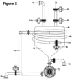
- Liquid hydrocarbons which should be anhydrous and preferably purified from coarse impurities and non-molecularly bound impurities, have to be introduced through entry 1) in liquid state into the vessel 4).
- the liquids should be heated in the vessel 4) to the desired treatment temperature before the sodium input.
- the hot fluid in the device then continuously flows from the lower part of the vessel 4) through pumping unit 7) through dispersing unit 8) through flow pipe 10) and through throttle valve 5), and is subjected to strong mechanical forces, high shear and adjustable pressure before returning at entry point 12) into vessel 4).
- the minimal, stoichiometric sodium amount required in ppm is equivalent to 1,5 times the ppm of the sulphur contained in the hydrocarbon liquid, but also depends on the treatment objective and possible other ingredients that could react with sodium.
- 0086 Sodium may be introduced into the device in solid or liquid state via the sodium input sluice 2), located at the upper part of the vessel 4).
- vessel 4 If oils in the range of middle distillate, boiling on from 160°C, are treated, vessel 4) has only to be kept under pressure of 4-6 bar, what is usually enough to maintain the oils in liquid state at treatment temperature, at 280°C.
- the necessary treatment time of liquid hydrocarbons in the device can amount, from the moment of sodium input, between 2 and 120 minutes, but using optimal sodium amounts and optimal pressure adjustments a treatment time between 5 and 20 minutes is sufficient.
- the oil and reaction products can leave the device through outlet 6), located at the lower part of the vessel 4), or through outlet 9), located after dispersing unit 8) in the pump- and dispersion circuit.
- the liquids can be decompressed through valve 6) or valve 9) into a settling tank, into a centrifuge, or preferably into a distillation device, whereby heat previously supplied to the treatment process, can also be used for the distillation.
Landscapes
- Chemical & Material Sciences (AREA)
- Chemical Kinetics & Catalysis (AREA)
- Organic Chemistry (AREA)
- Oil, Petroleum & Natural Gas (AREA)
- Engineering & Computer Science (AREA)
- General Chemical & Material Sciences (AREA)
- Production Of Liquid Hydrocarbon Mixture For Refining Petroleum (AREA)
Applications Claiming Priority (3)
| Application Number | Priority Date | Filing Date | Title |
|---|---|---|---|
| AU2018201581A AU2018201581B2 (en) | 2018-03-05 | 2018-03-05 | Method and Device for Treatment of of Liquid Hydrocarbons |
| PCT/EP2018/064235 WO2019170263A1 (en) | 2018-03-05 | 2018-05-30 | Method and device for treatment of liquid hydrocarbons |
| EP18731749.0A EP3762474B8 (de) | 2018-03-05 | 2018-05-30 | Verfahren zur behandlung von flüssigen kohlenwasserstoffen |
Related Parent Applications (2)
| Application Number | Title | Priority Date | Filing Date |
|---|---|---|---|
| EP18731749.0A Division-Into EP3762474B8 (de) | 2018-03-05 | 2018-05-30 | Verfahren zur behandlung von flüssigen kohlenwasserstoffen |
| EP18731749.0A Division EP3762474B8 (de) | 2018-03-05 | 2018-05-30 | Verfahren zur behandlung von flüssigen kohlenwasserstoffen |
Publications (2)
| Publication Number | Publication Date |
|---|---|
| EP4495210A2 true EP4495210A2 (de) | 2025-01-22 |
| EP4495210A3 EP4495210A3 (de) | 2025-04-09 |
Family
ID=62631049
Family Applications (2)
| Application Number | Title | Priority Date | Filing Date |
|---|---|---|---|
| EP24216322.8A Pending EP4495210A3 (de) | 2018-03-05 | 2018-05-30 | Verfahren und vorrichtung zur behandlung von flüssigen kohlenwasserstoffen |
| EP18731749.0A Active EP3762474B8 (de) | 2018-03-05 | 2018-05-30 | Verfahren zur behandlung von flüssigen kohlenwasserstoffen |
Family Applications After (1)
| Application Number | Title | Priority Date | Filing Date |
|---|---|---|---|
| EP18731749.0A Active EP3762474B8 (de) | 2018-03-05 | 2018-05-30 | Verfahren zur behandlung von flüssigen kohlenwasserstoffen |
Country Status (6)
| Country | Link |
|---|---|
| US (4) | US20200399545A1 (de) |
| EP (2) | EP4495210A3 (de) |
| AU (2) | AU2018201581B2 (de) |
| CA (1) | CA3093178A1 (de) |
| ES (1) | ES3013907T3 (de) |
| WO (1) | WO2019170263A1 (de) |
Families Citing this family (2)
| Publication number | Priority date | Publication date | Assignee | Title |
|---|---|---|---|---|
| AU2018201581B2 (en) * | 2018-03-05 | 2024-12-12 | Ecofuel Technologies Ltd | Method and Device for Treatment of of Liquid Hydrocarbons |
| CN112098261B (zh) * | 2020-08-03 | 2022-03-11 | 中国原子能科学研究院 | 一种用于高温高压下液体金属钠蒸发的装置及操作方法 |
Citations (2)
| Publication number | Priority date | Publication date | Assignee | Title |
|---|---|---|---|---|
| GB759283A (en) | 1952-12-24 | 1956-10-17 | British Petroleum Co | Improvements relating to the refining of petroleum hydrocarbons |
| US3166492A (en) | 1960-12-13 | 1965-01-19 | Degussa | Desulfurization of hydrocarbons |
Family Cites Families (4)
| Publication number | Priority date | Publication date | Assignee | Title |
|---|---|---|---|---|
| CA774540A (en) * | 1967-12-26 | National Distillers And Chemical Corporation | Continuous process for sodium dispersions | |
| CH595432A5 (en) * | 1974-09-13 | 1978-02-15 | Frank Barry Haskett | Removal of sulphur cpds. from oil fractions |
| WO2013142513A2 (en) * | 2012-03-21 | 2013-09-26 | H R D Corporation | Apparatus, system, and method for converting a first substance into a second substance |
| AU2018201581B2 (en) * | 2018-03-05 | 2024-12-12 | Ecofuel Technologies Ltd | Method and Device for Treatment of of Liquid Hydrocarbons |
-
2018
- 2018-03-05 AU AU2018201581A patent/AU2018201581B2/en active Active
- 2018-05-30 EP EP24216322.8A patent/EP4495210A3/de active Pending
- 2018-05-30 CA CA3093178A patent/CA3093178A1/en active Pending
- 2018-05-30 US US16/977,024 patent/US20200399545A1/en not_active Abandoned
- 2018-05-30 WO PCT/EP2018/064235 patent/WO2019170263A1/en not_active Ceased
- 2018-05-30 EP EP18731749.0A patent/EP3762474B8/de active Active
- 2018-05-30 ES ES18731749T patent/ES3013907T3/es active Active
-
2023
- 2023-08-16 US US18/450,972 patent/US12043805B2/en active Active
-
2024
- 2024-06-20 US US18/749,322 patent/US12281264B2/en active Active
-
2025
- 2025-03-11 AU AU2025201757A patent/AU2025201757A1/en active Pending
- 2025-03-31 US US19/096,377 patent/US20250230367A1/en active Pending
Patent Citations (2)
| Publication number | Priority date | Publication date | Assignee | Title |
|---|---|---|---|---|
| GB759283A (en) | 1952-12-24 | 1956-10-17 | British Petroleum Co | Improvements relating to the refining of petroleum hydrocarbons |
| US3166492A (en) | 1960-12-13 | 1965-01-19 | Degussa | Desulfurization of hydrocarbons |
Also Published As
| Publication number | Publication date |
|---|---|
| WO2019170263A1 (en) | 2019-09-12 |
| US12281264B2 (en) | 2025-04-22 |
| EP3762474C0 (de) | 2024-12-25 |
| CA3093178A1 (en) | 2019-09-12 |
| ES3013907T3 (en) | 2025-04-15 |
| AU2018201581B2 (en) | 2024-12-12 |
| US20250230367A1 (en) | 2025-07-17 |
| US20200399545A1 (en) | 2020-12-24 |
| AU2018201581A1 (en) | 2019-09-19 |
| EP3762474B8 (de) | 2025-02-19 |
| US20240417630A1 (en) | 2024-12-19 |
| US12043805B2 (en) | 2024-07-23 |
| EP3762474A1 (de) | 2021-01-13 |
| AU2025201757A1 (en) | 2025-04-03 |
| EP4495210A3 (de) | 2025-04-09 |
| US20230392081A1 (en) | 2023-12-07 |
| EP3762474B1 (de) | 2024-12-25 |
Similar Documents
| Publication | Publication Date | Title |
|---|---|---|
| US20250230367A1 (en) | Method and device for treatment of liquid hydrocarbons | |
| KR102105575B1 (ko) | 석유로부터 금속을 제거하는 방법 | |
| AU746498B2 (en) | Process to upgrade crude oils by destruction of naphthenic acids, removal of sulfur and removal of salts | |
| US10041005B2 (en) | Process and system for solvent addition to bitumen froth | |
| CA2707688C (en) | Process for the desulfurization of heavy oils and bitumens | |
| CN1839194B (zh) | 原油馏分、化石燃料及其产品的处理 | |
| US10577546B2 (en) | Systems and processes for deasphalting oil | |
| WO2011123383A1 (en) | Integrated hydrotreating and oxidative desulfurization process | |
| CN104204145B (zh) | 用己内酰铵离子液体从燃料料流中除去氮的方法 | |
| JP6117203B2 (ja) | 中間留分の選択的水素化処理方法 | |
| KR20000065147A (ko) | 오일/물/생촉매삼상의분리방법 | |
| US20100155298A1 (en) | Process for producing a high stability desulfurized heavy oils stream | |
| JP2019527615A (ja) | 超臨界水分離プロセス | |
| HK40119343A (en) | Method and device for treatment of liquid hydrocarbons | |
| RU2744853C1 (ru) | Способ физического разделения отходящих потоков нефтепереработки | |
| RU2685550C1 (ru) | Способ получения дизельных топлив с улучшенными низкотемпературными свойствами и уменьшенным содержанием серы и устройство для его реализации | |
| Noori et al. | Desulfurization of Light Distillate by Catalytic Oxidation Integrated with Emulsification | |
| WO2024168194A1 (en) | System and method for arsenic removal from hydrocarbon liquids | |
| EA011223B1 (ru) | Способ очищения жидких углеводородов и устройство для его осуществления | |
| HK1135427B (en) | Treatment of crude oil fractions, fossil fuels, and prodcuts thereof | |
| HK1097566B (en) | Treatment of crude oil fractions, fossil fuels, and products thereof |
Legal Events
| Date | Code | Title | Description |
|---|---|---|---|
| PUAI | Public reference made under article 153(3) epc to a published international application that has entered the european phase |
Free format text: ORIGINAL CODE: 0009012 |
|
| STAA | Information on the status of an ep patent application or granted ep patent |
Free format text: STATUS: THE APPLICATION HAS BEEN PUBLISHED |
|
| AC | Divisional application: reference to earlier application |
Ref document number: 3762474 Country of ref document: EP Kind code of ref document: P |
|
| AK | Designated contracting states |
Kind code of ref document: A2 Designated state(s): AL AT BE BG CH CY CZ DE DK EE ES FI FR GB GR HR HU IE IS IT LI LT LU LV MC MK MT NL NO PL PT RO RS SE SI SK SM TR |
|
| PUAL | Search report despatched |
Free format text: ORIGINAL CODE: 0009013 |
|
| AK | Designated contracting states |
Kind code of ref document: A3 Designated state(s): AL AT BE BG CH CY CZ DE DK EE ES FI FR GB GR HR HU IE IS IT LI LT LU LV MC MK MT NL NO PL PT RO RS SE SI SK SM TR |
|
| RIC1 | Information provided on ipc code assigned before grant |
Ipc: B01J 8/22 20060101ALI20250304BHEP Ipc: C10G 29/04 20060101AFI20250304BHEP |
|
| REG | Reference to a national code |
Ref country code: HK Ref legal event code: DE Ref document number: 40119343 Country of ref document: HK |
|
| STAA | Information on the status of an ep patent application or granted ep patent |
Free format text: STATUS: REQUEST FOR EXAMINATION WAS MADE |
|
| 17P | Request for examination filed |
Effective date: 20251008 |