EP4494533A1 - Kochgerät - Google Patents
Kochgerät Download PDFInfo
- Publication number
- EP4494533A1 EP4494533A1 EP22939418.4A EP22939418A EP4494533A1 EP 4494533 A1 EP4494533 A1 EP 4494533A1 EP 22939418 A EP22939418 A EP 22939418A EP 4494533 A1 EP4494533 A1 EP 4494533A1
- Authority
- EP
- European Patent Office
- Prior art keywords
- heat
- housing
- inner cavity
- fan blade
- cooking appliance
- Prior art date
- Legal status (The legal status is an assumption and is not a legal conclusion. Google has not performed a legal analysis and makes no representation as to the accuracy of the status listed.)
- Pending
Links
Images

Classifications
-
- A—HUMAN NECESSITIES
- A47—FURNITURE; DOMESTIC ARTICLES OR APPLIANCES; COFFEE MILLS; SPICE MILLS; SUCTION CLEANERS IN GENERAL
- A47J—KITCHEN EQUIPMENT; COFFEE MILLS; SPICE MILLS; APPARATUS FOR MAKING BEVERAGES
- A47J37/00—Baking; Roasting; Grilling; Frying
- A47J37/06—Roasters; Grills; Sandwich grills
- A47J37/0623—Small-size cooking ovens, i.e. defining an at least partially closed cooking cavity
- A47J37/0629—Small-size cooking ovens, i.e. defining an at least partially closed cooking cavity with electric heating elements
- A47J37/0641—Small-size cooking ovens, i.e. defining an at least partially closed cooking cavity with electric heating elements with forced air circulation, e.g. air fryers
-
- F—MECHANICAL ENGINEERING; LIGHTING; HEATING; WEAPONS; BLASTING
- F24—HEATING; RANGES; VENTILATING
- F24C—DOMESTIC STOVES OR RANGES ; DETAILS OF DOMESTIC STOVES OR RANGES, OF GENERAL APPLICATION
- F24C15/00—Details
- F24C15/006—Arrangements for circulation of cooling air
Definitions
- the present application belongs to the technical field of household electrical appliances, and in particular, relates to a cooking appliance.
- An air fryer is a machine that may use air to "fry", and mainly uses the air to replace an originally hot oil in a frying pan to cook food. Meanwhile, the hot air also blows away moisture on a surface of the food, making a food material achieve an approximate effect of being fried.
- the cooking appliance includes a housing, an air inlet, an air outlet, a heat-dissipation channel, and a heat-dissipation assembly.
- the housing has a rear side, and a first side and a second side that are adjacent to the rear side. The first side and the second side are located at two opposite sides of the housing.
- the air inlet is formed at the first side.
- the air outlet is formed at the second side.
- the heat-dissipation channel is disposed in the housing and in communication with the air inlet and the air outlet.
- the heat-dissipation assembly is disposed in the heat-dissipation channel.
- the heat-dissipation assembly is configured to discharge a gas outside the housing out of the air outlet from the air inlet via the heat-dissipation channel.
- the housing has the rear side, and the first side and the second side that are adjacent to the rear side.
- the air inlet of the housing is formed at the first side of the housing, and the air outlet of the housing may be formed at the second side of the housing.
- the housing of the cooking appliance may abut against a wall surface. Since the air inlet and air outlet of the housing are respectively disposed at the first side and the second side of the housing, the air inlet and air outlet of the housing are not blocked by the wall surface.
- the heat-dissipation assembly may sufficiently suck a normal-temperature gas or a cold gas outside the housing into the heat-dissipation channel of the housing from the air inlet of the housing, and sufficiently discharge a hot gas in the heat-dissipation channel out of the housing from the air outlet of the housing, to cause the cooking appliance to have good heat-dissipation performance.
- each of an angle between an orientation of the air inlet and the rear side and an angle between the orientation of the air inlet and the first side is smaller than 90 degrees.
- Each of an angle between an orientation of the air outlet and the rear side and an angle between the orientation of the air outlet and the second side is smaller than 90 degrees.
- the first side includes a first side section and a first transition section.
- the first side section is connected to the rear side through the first transition section.
- the first transition section includes at least one of a fillet transition and a chamfer transition.
- the air inlet is at least partially disposed at the first transition section.
- the second side includes a second side section and a second transition section.
- the second side section is connected to the rear side through the second transition section.
- the second transition section includes at least one of the fillet transition and the chamfer transition.
- the air outlet is at least partially disposed at the second transition section.
- the first transition section is spaced apart from the second transition section by a first spacing.
- the first side is spaced apart from the second side by a second spacing.
- the first spacing is smaller than the second spacing.
- the cooking appliance further includes a heating assembly and an inner casing.
- the inner casing is disposed in the housing.
- a gap is formed between the inner casing and the housing.
- the heat-dissipation channel is located in the gap.
- the inner casing has a cooking cavity for accommodating a food material.
- the heating assembly is disposed in the housing to heat the food material in the cooking cavity.
- the heat-dissipation assembly includes a driver and a first fan blade connected to the driver.
- the heat-dissipation channel is located between the inner casing and an inner wall of the rear side.
- the first fan blade is a centrifugal fan blade, and an axial direction of the first fan blade is perpendicular to the rear side.
- the cooking appliance further includes a partition.
- the partition is disposed in the cooking cavity to divide the cooking cavity into a first inner cavity and a second inner cavity.
- the first inner cavity is superposed on the second inner cavity.
- the heating assembly includes a first heating portion and a second heating portion.
- the first heating portion is configured to heat the first cavity.
- the second heating portion is configured to heat the second cavity.
- Two heat-dissipation assemblies are provided. The two heat-dissipation assemblies cooperate with the first heating portion and the second heating portion, respectively.
- the two heat-dissipation assemblies, two air inlets, and two air outlets are provided.
- the two heat-dissipation assemblies correspond to the first inner cavity and the second inner cavity, respectively.
- the two air inlets correspond to the two heat-dissipation assemblies, respectively.
- the two air outlets correspond to the two heat-dissipation assemblies, respectively.
- the first heating portion includes a second fan blade and a first heat producing element.
- the driver of the heat-dissipation assembly of the two heat-dissipation assemblies corresponding to the first inner cavity is connected to the second fan blade.
- the second fan blade is located in the first inner cavity, and the first heat producing element is disposed in the first inner cavity.
- the second heating portion includes a third fan blade and a second heat producing element.
- the driver of the heat-dissipation assembly of the two heat-dissipation assemblies corresponding to the second inner cavity is connected to the third fan blade.
- the third fan blade is located in the second inner cavity, and the second heat producing element is disposed in the first inner cavity.
- the cooking appliance further includes a heat insulation portion.
- the partition has a cavity, and the heat insulation portion is disposed in the cavity.
- connection In the present application, unless otherwise clearly specified and limited, terms such as “connect”, “connect to”, “fix” and the like should be understood in a broad sense. For example, it may be a fixed connection or a detachable connection or connection as one piece; a mechanical connection or an electrical connection; a direct connection or an indirect connection through an intermediate; internal communication of two components or an interaction relationship between two components.
- connect In the present application, unless otherwise clearly specified and limited, terms such as “connect”, “connect to”, “fix” and the like should be understood in a broad sense. For example, it may be a fixed connection or a detachable connection or connection as one piece; a mechanical connection or an electrical connection; a direct connection or an indirect connection through an intermediate; internal communication of two components or an interaction relationship between two components.
- the embodiments of the present application disclose a cooking appliance, including a housing 100 and a heat-dissipation assembly 400.
- the cooking appliance may be applied in cooking devices such as an air fryer, an oven, and a microwave oven.
- the housing 100 is a basic component of the cooking appliance of the present application.
- the housing 100 may provide a mounting base for at least some of the other components of the cooking appliance, and may also achieve a purpose of protecting at least some of the other components in the housing 100.
- the housing 100 may also provide a cooking cavity for a food material to be cooked.
- the housing 100 is provided with an air inlet 142a and an air outlet 152a, and is internally provided with a heat-dissipation channel 160.
- the heat-dissipation channel 160 in the housing 100 is in communication with both the air inlet 142a and the air outlet 152a of the housing 100.
- a normal-temperature gas or a cold gas outside the housing 100 may enter the heat-dissipation channel 160 in the housing 100 from the air inlet 142a of the housing 100, and may absorb heat in the housing 100 and is discharged to outside of the housing 100 from the air outlet 152a of the housing 100, to achieve a heat dissipation purpose in the housing 100, preventing a temperature of a part of the housing 100 except for the cooking cavity from being too high.
- the heat-dissipation assembly 400 is disposed in the heat-dissipation channel 160 of the housing 100.
- the heat-dissipation assembly 400 may suck the normal-temperature gas or the cold gas outside the housing 100 into the heat-dissipation channel 160 from the air inlet 142a of the housing 100.
- the normal-temperature gas or the cold gas in the heat-dissipation channel 160 may become a hot gas after absorbing the heat in the housing 100, and the heat-dissipation assembly 400 may discharge the hot gas to the outside of the housing 100 from the air outlet 152a of the housing 100.
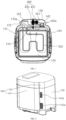
- the housing 100 has a rear side 130.
- the rear side 130 of the cooking appliance may abut with an indoor wall surface. In this way, waste of the indoor space can be prevented. Meanwhile, the wall surface may support the cooking appliance by abutting with the rear side 130 of the cooking appliance, making the cooking appliance be kept stable.
- the housing 100 also has a first side 140 and a second side 150. Both the first side 140 and the second side 150 of the housing 100 are adjacent to the rear side 130 of the housing 100. Moreover, the first side 140 and the second side 150 are located at two opposite sides of the housing 100. In this way, neither the first side 140 of the housing 100 nor the second side 150 of the housing 100 are blocked by the wall surface when the rear side 130 of the housing 100 abuts with the wall surface.
- the air inlet 142a and the air outlet 152a of the housing 100 may be disposed at the first side 140 and the second side 150 of the housing 100, respectively.
- the air inlet 142a and the air outlet 152a of the housing 100 are not blocked by the wall surface, enabling the normal-temperature gas or the cold gas outside the housing 100 to sufficiently enter the heat-dissipation channel 160 in the housing 100 from the air inlet 142a of the housing 100, and enabling the hot gas in the heat-dissipation channel 160 to be sufficiently discharged to the outside of the housing 100 from the air outlet 152a of the housing 100.
- the heat-dissipation assembly 400 may sufficiently suck the normal-temperature gas or the cold gas outside the housing 100 into the heat-dissipation channel 160 of the housing 100 from the air inlet 142a of the housing 100, and sufficiently discharge the hot gas inside the heat-dissipation channel 160 out of the housing 100 from the air outlet 152a of the housing 100. In this way, the cooking appliance can still have a good heat-dissipation effect in a case where the cooking appliance is mounted and arranged compactly and reasonably.
- the housing 100 has the rear side 130, and the first side 140 and the second side 150 that are adjacent to the rear side 130.
- the air inlet 142a of the housing 100 is formed at the first side 140 of the housing 100
- the air outlet 152a of the housing 100 is formed at the second side 150 of the housing 100.
- the heat-dissipation assembly 400 may sufficiently suck the normal-temperature gas or the cold gas outside the housing 100 into the heat-dissipation channel 160 of the housing 100 from the air inlet 142a of the housing 100, and sufficiently discharge the hot gas in the heat-dissipation channel 160 out of the housing 100 from the air outlet 152a of the housing 100, to cause the cooking appliance to have good heat-dissipation performance.
- the cooking appliance in order to make full use of the indoor space when the cooking appliance of the present application is placed in an indoor environment, the cooking appliance may be placed at an indoor wall corner. In this way, a space at the indoor wall corner can be fully utilized, and two wall surfaces of the wall corner may abut with the housing 100 simultaneously, making the housing 100 more stable.
- the housing 100 When the cooking appliance is placed at the wall corner, at least two sides of the housing 100 abut with the wall surface.
- the rear side 130 and the first side 140 of the housing 100 may abut with the wall surface. Therefore, in order to prevent the air inlet 142a formed at the first side 140 of the housing 100 from being blocked by the wall surface, in the present application, an angle between an opening direction of the air inlet 142a and the rear side 130 is smaller than 90 degrees. In this way, when the rear side 130 of the housing 100 abuts with the wall surface, the air inlet 142a does not directly face towards the wall surface, enabling the air inlet 142a not to be blocked by the wall surface.
- An angle between the opening direction of the air inlet 142a and the first side 140 is also set to be smaller than 90 degrees. In this way, when the first side 140 of the housing 100 abuts with the wall surface, the air inlet 142a does not directly face towards the wall surface, enabling the air inlet 142a not to be blocked by the wall surface either.
- the first side 140 of the housing 100 of the present application may be configured to include a first side section 141 and a first transition section 142.
- the first side section 141 of the first side 140 is connected to the rear side 130 of the housing 100 through the first transition section 142.
- the first transition section 142 may be provided as a fillet transition, a chamfer transition, or a combination structure of the fillet transition and the chamfer transition. In this way, when the cooking appliance is placed at the wall corner, the rear side 130 and the first side section 141 of the housing 100 may abut with two adjacent wall surfaces, respectively.
- the first transition section 142 may be spaced apart from the wall corner by a predetermined gap, enabling the first transition section 142 not to be completely blocked by the wall surface.
- At least part of the air inlet 142a of the housing 100 may be formed at the first transition section 142, to ensure that the normal-temperature gas or the cold gas outside the housing 100 may enter the heat-dissipation channel 160 of the housing 100 from at least the part of the air inlet 142a located at the first transition section 142. In this way, when the cooking appliance of the present application is placed at the wall corner, the heat-dissipation assembly 400 may still allow the normal-temperature gas or the cold gas outside the housing 100 to enter the heat-dissipation channel 160 of the housing 100.
- the at least two sides of the housing 100 abut with the wall surface.
- the rear side 130 and the second side 150 of the housing 100 may also abut with the wall surface. Therefore, in order to prevent the air outlet 152a formed at the second side 150 of the housing 100 from being blocked by the wall surface, in the present application, an angle between an opening direction of the air outlet 152a and the rear side 130 is smaller than 90 degrees. In this way, when the rear side 130 of the housing 100 abuts with the wall surface, the air outlet 152a does not directly face towards the wall surface, enabling the air outlet 152a not to be blocked by the wall surface.
- An angle between the opening direction of the air outlet 152a and the second side 150 is also set to be smaller than 90 degrees. In this way, when the second side 150 of the housing 100 abuts with the wall surface, the air outlet 152a does not directly face towards the wall surface, enabling the air outlet 152a not to be blocked by the wall surface either.
- the second side 150 of the housing 100 of the present application may be configured to include a second side section 151 and a second transition section 152.
- the second side section 151 of the second side 150 is connected to the rear side 130 of the housing 100 through the second transition section 152.
- the second transition section 152 may be provided as the fillet transition, the chamfer transition, or the combination structure of the fillet transition and the chamfer transition. In this way, when the cooking appliance is placed at the wall corner, the rear side 130 and the second side section 151 of the housing 100 may abut with two adjacent wall surfaces, respectively.
- the second transition section 152 may be spaced apart from the wall corner by a predetermined gap, enabling the second transition section 152 not to be completely blocked by the wall surface.
- At least part of the air outlet 152a of the housing 100 may be formed at the second transition section 152, to ensure that the hot gas in the heat-dissipation channel 160 of the housing 100 may be discharged to the outside of the housing 100 from at least the part of the air outlet 152a located at the second transition section 152.
- the heat-dissipation assembly 400 may allow the hot gas in the heat-dissipation channel 160 of the housing 100 to be discharged to the outside of the housing 100.
- the first side 140 of the housing 100 of the present application may be provided with the first transition section 142
- the second side 150 of the housing 100 of the present application may be provided with the second transition section 152.
- the air inlet 142a and the air outlet 152a of the housing 100 may be at least partially formed at the first transition section 142 and the second transition section 152, respectively.
- each of the rear side 130, the first side 140, and the second side 150 of the cooking appliance may abut with the wall surface. In this way, the cooking appliance can be made more stable when placed in the indoor space, and the groove-shaped space can also achieve a purpose of protecting the cooking appliance.
- the air inlet 142a and the air outlet 152a of the housing 100 may be formed at the first transition section 142 and the second transition section 152, respectively. In this way, the air inlet 142a and the air outlet 152a of the housing 100 are both not completely blocked by the wall surface, enabling the normal-temperature gas or the cold gas outside the housing 100 to be sucked by the heat-dissipation assembly 400 into the heat-dissipation channel 160 of the housing 100 from the air inlet 142a of the housing 100, and enabling the hot gas in the heat-dissipation channel 160 to be discharged by the heat-dissipation assembly 400 to the outside of the housing 100 from the air outlet 152a of the housing 100.
- first chamfer section 142 and the second chamfer section 152 are at least one of the fillet transition and the chamfer transition, or one of the first chamfer section 142 and the second chamfer section 152 is at least one of the fillet transition and the chamfer transition, the first chamfer section 142 is spaced apart from the second chamfer section 152 by a first spacing, and the first side section 141 is spaced apart from the second side section 151 by a second spacing.
- the first spacing is smaller than the second spacing.
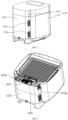
- the heat-dissipation assembly 400 of the present application may be configured to include a driver 410 and a first fan blade 420.
- the first fan blade 420 is connected to the driver 410.
- the driver 410 may drive the first fan blade 420 to rotate.
- the first fan blade 420 rotates to generate wind power to suck the normal-temperature gas or the cold gas outside the housing 100 into the heat-dissipation channel 160 of the housing 100 from the air inlet 142a of the housing 100, and to discharge the hot gas in the heat-dissipation channel 160 to the outside of the housing 100 from the air outlet 152a of the housing 100.
- the driver 410 also generates heat when driving the first fan blade 420 to rotate. Since the driver 410 is disposed in the heat-dissipation channel 160, the heat generated by the driver 410 is diffused into the heat-dissipation channel 160. When the first fan blade 420 rotates, the heat generated by the driver 410 may be discharged to the outside of the housing 100 from the air outlet 152a of the housing 100, to achieve a purpose of dissipating the heat of the driver 410. In this way, the heat-dissipation assembly 400 of the present application can be made more stable and reliable.
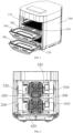
- the cooking appliance of the present application may further be provided with a partition 300.
- the partition 300 may be disposed in the housing 100, and specifically disposed inside the inner casing 200.
- the partition 300 may divide the cooking cavity in the inner casing 200 into a first inner cavity 110 and a second inner cavity 120.
- the first inner cavity 110 and the second inner cavity 120 may be configured to accommodate the food material to be cooked.
- different types of food material may be placed in the first inner cavity 110 and the second inner cavity 120. Therefore, such different types of food material can be cooked in the first inner cavity 110 and the second inner cavity 120, respectively, which can prevent the different types of food material from affecting each other during cooking.
- the first inner cavity 110 may be superposed on the second inner cavity 120, which makes a width of the cooking appliance of the present application relatively small, and further makes the structure of the cooking appliance more compact.
- the housing 100 provides a mounting base for the first heating portion and the second heating portion, making both the first heating portion and the second heating portion disposed in the housing 100.
- the first heating portion may heat the first inner cavity 110, and thus may heat the food material accommodated in the first inner cavity 110, to achieve a purpose of cooking the food material in the first inner cavity 110.
- the second heating portion may heat the second inner cavity 120, and thus may heat the food material accommodated in the second inner cavity 120, to achieve a purpose of cooking the food material in the second inner cavity 120.
- the first heating portion may control a temperature in the first inner cavity 110, making the temperature in the first inner cavity 110 variable.
- the first heating portion may control the temperature in the first inner cavity 110 to reach a temperature most suitable for cooking the food materials, making cooking effects of the food materials better.
- the second heating portion may control a temperature in the second inner cavity 120, making the temperature in the second inner cavity 120 variable.
- the different types of food materials may have different cooking temperature requirements, and the second heating portion may control the temperature in the second inner cavity 120 to reach the temperature most suitable for cooking the food materials, making the cooking effects of the food materials better.
- the first heating portion and the second heating portion control the temperature of the first inner cavity 110 and the temperature of the second inner cavity 120, respectively.
- the first inner cavity 110 and the second inner cavity 120 are separated from and independent of each other.
- the first heating portion and the second heating portion may heat the food material in the first inner cavity 110 and the food material in the second inner cavity 120, respectively.
- the temperature of the first inner cavity 110 and the temperature of the second inner cavity 120 can be respectively adjusted to temperatures suitable for cooking different food materials.
- different types of food materials may be respectively placed in the first inner cavity 110 and the second inner cavity 120 for simultaneous cooking, to improve the cooking efficiency of the cooking appliance of the present application.
- Wind power generated by the second fan blade 510 as it rotates may dry the moisture and oil on surface of the food material, to achieve a purpose of air-frying the food material.
- the second fan blade 510 and the first heat producing element 520 may be arranged relatively close to each other. In this way, the second fan blade 510 can quickly blow the hot gas generated by the first heat producing element 520 to the food material to be cooked in the first inner cavity 110.
- two first heat producing elements 520 may also be provided.
- the two first heat producing elements 520 may be disposed at a bottom and a top of the first inner cavity 110, respectively. In this way, when the food material are placed in the first inner cavity 110, the two first heat producing elements 520 may respectively heat a bottom side and a top side of the food material, to achieve a purpose of sufficiently heating the food material.
- the second heating portion of the present application may be configured to include a third fan blade 610 and a second heat producing element 620.
- the second heat producing element 620 may be disposed at a top of the second inner cavity 120, and the third fan blade 610 may be disposed at a side of the second inner cavity 120.
- the third fan blade 610 and the second heat producing element 620 may be distributed at different positions of the second inner cavity 120, to prevent the third fan blade 610 and the second heat producing element 620 from being concentrated at a predetermined position in the second inner cavity 120, making mounting of the third fan blade 610 and the second heat producing element 620 be facilitated.
- the second heat producing element 620 may heat air in the second inner cavity 120, which makes an increase in the temperature of the second inner cavity 120, and further makes the food material accommodated in the second inner cavity 120 to be heated. Moisture and oil inside the food material accommodated in the second inner cavity 120 after the food material being heated may seep from the food material, and an air outlet direction of the third fan blade 610 may be directed towards the food material accommodated in the second inner cavity 120. In this way, wind power generated by the third fan blade 610 may blow off the oil and moisture seeping from the food material accommodated in the second inner cavity 120, enabling the oil and moisture seeping from the food material to be separated from the food material, to achieve a purpose of cooking the food material by air-frying.
- the second inner cavity 120 has a second containing portion for accommodating the food material, and the food material may be stacked at a predetermined height after being placed in the second containing portion.
- a direction of the wind power generated by the third fan blade 610 may be parallel to a bottom of the second inner cavity 120. In this way, the third fan blade 610 can blow wind towards a side of the food material accommodated on the second containing portion, and a purpose of separating the oil and moisture seeping from the surface of the food material from the food material can also be achieved.
- the second heat producing element 620 and the third fan blade 610 may also be disposed at the same side of the second inner cavity 120. In this way, a purpose of heating the food material and separating the oil and moisture of the food material from the food material can also be achieved.
- the second heating portion may be further configured to include two second heat producing elements 620.
- the two second heat producing elements 620 may be respectively disposed at a bottom and a top of the second inner cavity 120, and arranged opposite to each other.
- the two second heat producing elements 620 may heat the bottom and top of the food material, respectively. In this way, the food material can be heated in multiple directions.
- the temperature in the second inner cavity 120 can reach a temperature required for cooking the food material more efficiently.
- two heat-dissipation assemblies 400 of the present application may be provided, and the two heat-dissipation assemblies 400 may be provided corresponding to the first inner cavity 110 and the second inner cavity 120, respectively.
- a driver 410 of the heat-dissipation assembly 400 corresponding to the first inner cavity 110 may be configured to be connected to the second fan blade 510, and the second fan blade 510 is located in the first inner cavity 110. In this way, the driver 410 can drive the first fan blade 420 and the second fan blade 510 to rotate simultaneously as it rotates.
- the driver 410 of the heat-dissipation assembly 400 may adopt the motor.
- a rotary shaft of one of drivers 410 may be configured to pass through the inner casing 200 and extend to the first inner cavity 110, and the second fan blade 510 is connected to the rotary shaft of the driver 410.
- the driver 410 can simultaneously drive the first fan blade 420 and the second fan blade 510 to rotate.
- the first fan blade 420 can achieve the purpose of dissipating the heat of the cooking appliance
- the second fan blade 510 can play a role in enabling the hot gas in the first inner cavity 110 to be flowable, enabling the hot gas to act on the food material in the first inner cavity 110.
- the first fan blade 420 and the second fan blade 510 are simultaneously driven by one driver 410 to rotate, which can reduce the quantity of parts of the cooking appliance of the present application, enabling the structure of the cooking appliance to become simpler and more compact.
- a rotary shaft of another one of drivers 410 410 may be configured to pass through the inner casing 200 and extend to the second inner cavity 120, and the third fan blade 610 is connected to the rotary shaft of the driver 410.
- the driver 410 can simultaneously drive the first fan blade 420 and the third fan blade 610 to rotate.
- the first fan blade 420 can achieve the purpose of dissipating the heat of the cooking appliance, and the third fan blade 610 can play a role in enabling the hot gas in the second inner cavity 120 to be flowable, enabling the hot gas to act on the food material in the second inner cavity 120.
- the first fan blade 420 and the third fan blade 610 are simultaneously driven by one driver 410 to rotate, which can reduce the quantity of parts of the cooking appliance of the present application, enabling the structure of the cooking appliance to become simpler and more compact.
- the heat inside the housing 100 may be more efficiently discharged to the outside of the housing 100.
- two air inlets 142a and two air outlets 152a of the housing 100 may also be provided, the two air inlets 142a may correspond to the two heat-dissipation assemblies 400 respectively, and the two air outlets 152a may correspond to the two heat-dissipation assemblies 400 respectively.
- the housing in order to facilitate access to a food material in each of the first inner cavity 110 and the second inner cavity 120, may be provided with an opening corresponding to each of the first inner cavity 110 and the second inner cavity 120 and a door sheet 700.
- the door sheet 700 may enable a first opening and a second opening to be openable or closable.
- the partition 200 may also be provided as a heat insulation member.
- the partition 200 may be internally provided with a heat insulation cavity.
- the heat insulation cavity may be internally filled with heat insulation portions 210, and the heat insulation portions 210 may specifically use mica sheets, enabling the partition 200 to have good heat insulation performance.
- the first inner cavity 110 can be separated independently from the second inner cavity 120, and the heat in the first inner cavity 110 and the heat in the second inner cavity 120 can be prevented from affecting each other.
- a tray 170 may also be disposed in each of the first inner cavity 110 and the second inner cavity 120 of the present application.
- the food material heated in each of the first inner cavity 110 and the second inner cavity 120 may be placed on the tray 170.
- the oil and moisture seeping from the food material in each of the first inner cavity 110 and the second inner cavity 120 after being air-fried fall onto the tray 170, to prevent the oil and moisture from being scattered to components in each of the first inner cavity 110 and the second inner cavity 120, making it more convenient for the user to clean the first inner cavity 110 and the second inner cavity 120.
Landscapes
- Engineering & Computer Science (AREA)
- Food Science & Technology (AREA)
- Chemical & Material Sciences (AREA)
- Combustion & Propulsion (AREA)
- Mechanical Engineering (AREA)
- General Engineering & Computer Science (AREA)
- Cookers (AREA)
Applications Claiming Priority (2)
| Application Number | Priority Date | Filing Date | Title |
|---|---|---|---|
| CN202210435162.2A CN116965692A (zh) | 2022-04-24 | 2022-04-24 | 一种烹饪器具 |
| PCT/CN2022/090788 WO2023206574A1 (zh) | 2022-04-24 | 2022-04-29 | 烹饪器具 |
Publications (2)
| Publication Number | Publication Date |
|---|---|
| EP4494533A1 true EP4494533A1 (de) | 2025-01-22 |
| EP4494533A4 EP4494533A4 (de) | 2025-06-11 |
Family
ID=88481911
Family Applications (1)
| Application Number | Title | Priority Date | Filing Date |
|---|---|---|---|
| EP22939418.4A Pending EP4494533A4 (de) | 2022-04-24 | 2022-04-29 | Kochgerät |
Country Status (4)
| Country | Link |
|---|---|
| US (1) | US20250251137A1 (de) |
| EP (1) | EP4494533A4 (de) |
| CN (1) | CN116965692A (de) |
| WO (1) | WO2023206574A1 (de) |
Family Cites Families (20)
| Publication number | Priority date | Publication date | Assignee | Title |
|---|---|---|---|---|
| GB0714365D0 (en) * | 2007-07-21 | 2007-09-05 | Aga Consumer Products Ltd | A cooking appliance |
| US9027470B1 (en) * | 2011-03-18 | 2015-05-12 | Meister Cook Llc | Food condition maintaining device |
| CN106247521A (zh) * | 2016-09-30 | 2016-12-21 | 美的集团武汉制冷设备有限公司 | 竖式壁挂空调室内机及空调器 |
| CN108771489B (zh) * | 2018-08-14 | 2024-01-09 | 佛山市顺德区酷福电器有限公司 | 一种高效散热的电烹饪器具 |
| CN108852029B (zh) * | 2018-08-20 | 2024-08-02 | 广东格兰仕集团有限公司 | 电烤箱的双重散热结构 |
| CN109645847A (zh) * | 2019-02-15 | 2019-04-19 | 广东美的厨房电器制造有限公司 | 烹饪装置 |
| CN210121081U (zh) * | 2019-03-01 | 2020-03-03 | 广东美的厨房电器制造有限公司 | 热风装置和具有其的烹饪设备 |
| CN210227877U (zh) * | 2019-05-22 | 2020-04-03 | 广东美的生活电器制造有限公司 | 烹饪器具 |
| CN110547694A (zh) * | 2019-08-07 | 2019-12-10 | 浙江柯蓝工贸有限公司 | 一种多功能空气炸锅 |
| CN211582688U (zh) * | 2019-09-29 | 2020-09-29 | 浙江苏泊尔家电制造有限公司 | 煲体及具有其的烹饪器具 |
| CN211796000U (zh) * | 2020-01-17 | 2020-10-30 | 广东美的生活电器制造有限公司 | 空气炸锅 |
| CN113133684B (zh) * | 2020-01-17 | 2023-10-24 | 广东美的生活电器制造有限公司 | 空气炸锅 |
| CN112168006A (zh) * | 2020-09-25 | 2021-01-05 | 中山市格福美电器有限公司 | 一种新型的空气烤箱 |
| CN112167955B (zh) * | 2020-10-10 | 2022-09-20 | 广东美的厨房电器制造有限公司 | 烹饪器具的散热组件和具有其的烹饪器具 |
| CN213850212U (zh) * | 2020-11-24 | 2021-08-03 | 宁波市嘉乐电器有限公司 | 一种新型空气炸锅冷却系统 |
| CN214804239U (zh) * | 2020-12-31 | 2021-11-23 | 广东美的生活电器制造有限公司 | 上盖组件和煎烤机 |
| CN214259080U (zh) * | 2020-12-31 | 2021-09-24 | 广东美的生活电器制造有限公司 | 煎烤机 |
| CN215738494U (zh) * | 2021-01-08 | 2022-02-08 | 杨振巧 | 一种空气炸锅 |
| CN113143043A (zh) * | 2021-02-04 | 2021-07-23 | 宁波嘉乐智能科技股份有限公司 | 一种空气炸锅的散热系统 |
| CN215226913U (zh) * | 2021-04-20 | 2021-12-21 | 广东英为拓科技有限公司 | 一种空气烤箱 |
-
2022
- 2022-04-24 CN CN202210435162.2A patent/CN116965692A/zh active Pending
- 2022-04-29 EP EP22939418.4A patent/EP4494533A4/de active Pending
- 2022-04-29 WO PCT/CN2022/090788 patent/WO2023206574A1/zh not_active Ceased
- 2022-04-29 US US18/856,872 patent/US20250251137A1/en active Pending
Also Published As
| Publication number | Publication date |
|---|---|
| CN116965692A (zh) | 2023-10-31 |
| WO2023206574A1 (zh) | 2023-11-02 |
| US20250251137A1 (en) | 2025-08-07 |
| EP4494533A4 (de) | 2025-06-11 |
Similar Documents
| Publication | Publication Date | Title |
|---|---|---|
| CN110179324A (zh) | 烹饪装置 | |
| CN210673107U (zh) | 烤箱 | |
| CN118452710A (zh) | 烹饪器具 | |
| EP4494533A1 (de) | Kochgerät | |
| CN217744064U (zh) | 一种烹饪器具 | |
| CN217792630U (zh) | 多室烤箱 | |
| CN217090412U (zh) | 烹饪设备 | |
| WO2023207075A1 (zh) | 一种烹饪器具 | |
| US20250134304A1 (en) | Upper core device and cooking appliance | |
| CN215533738U (zh) | 一种烘烤效果好的食物烹饪器具 | |
| JP2000332474A (ja) | 電気部品の冷却構造 | |
| CN118557083A (zh) | 烹饪器具 | |
| CN219166206U (zh) | 一种空气炸锅 | |
| CN217744065U (zh) | 一种烹饪器具 | |
| EP4336969B1 (de) | Mikrowellenerzeugungssystem für kochgerät und kochgerät | |
| US12527430B2 (en) | Multi-chamber oven | |
| CN211559755U (zh) | 换热组件、烹饪设备 | |
| CN111053452B (zh) | 换热组件、烹饪设备 | |
| CN216358502U (zh) | 加热组件、加热装置和烹饪器具 | |
| CN221205143U (zh) | 空气炸锅的炉头和空气炸锅 | |
| CN223287037U (zh) | 一种易于散热的厨师机 | |
| CN223929993U (zh) | 空气炸锅 | |
| CN221903342U (zh) | 空气炸锅 | |
| CN114831581A (zh) | 热风装置和洗碗机 | |
| CN216554536U (zh) | 一种用于空炸烤箱的风机组件 |
Legal Events
| Date | Code | Title | Description |
|---|---|---|---|
| STAA | Information on the status of an ep patent application or granted ep patent |
Free format text: STATUS: THE INTERNATIONAL PUBLICATION HAS BEEN MADE |
|
| PUAI | Public reference made under article 153(3) epc to a published international application that has entered the european phase |
Free format text: ORIGINAL CODE: 0009012 |
|
| STAA | Information on the status of an ep patent application or granted ep patent |
Free format text: STATUS: REQUEST FOR EXAMINATION WAS MADE |
|
| 17P | Request for examination filed |
Effective date: 20241018 |
|
| AK | Designated contracting states |
Kind code of ref document: A1 Designated state(s): AL AT BE BG CH CY CZ DE DK EE ES FI FR GB GR HR HU IE IS IT LI LT LU LV MC MK MT NL NO PL PT RO RS SE SI SK SM TR |
|
| A4 | Supplementary search report drawn up and despatched |
Effective date: 20250512 |
|
| RIC1 | Information provided on ipc code assigned before grant |
Ipc: A47J 37/06 20060101AFI20250506BHEP |
|
| DAV | Request for validation of the european patent (deleted) | ||
| DAX | Request for extension of the european patent (deleted) |