EP4494513B1 - Wickelvorrichtung - Google Patents
Wickelvorrichtung Download PDFInfo
- Publication number
- EP4494513B1 EP4494513B1 EP24150153.5A EP24150153A EP4494513B1 EP 4494513 B1 EP4494513 B1 EP 4494513B1 EP 24150153 A EP24150153 A EP 24150153A EP 4494513 B1 EP4494513 B1 EP 4494513B1
- Authority
- EP
- European Patent Office
- Prior art keywords
- clamping
- knob
- reel
- housing
- guide
- Prior art date
- Legal status (The legal status is an assumption and is not a legal conclusion. Google has not performed a legal analysis and makes no representation as to the accuracy of the status listed.)
- Active
Links
Images


Classifications
-
- A—HUMAN NECESSITIES
- A43—FOOTWEAR
- A43C—FASTENINGS OR ATTACHMENTS OF FOOTWEAR; LACES IN GENERAL
- A43C11/00—Other fastenings specially adapted for shoes
- A43C11/16—Fastenings secured by wire, bolts, or the like
- A43C11/165—Fastenings secured by wire, bolts, or the like characterised by a spool, reel or pulley for winding up cables, laces or straps by rotation
-
- A—HUMAN NECESSITIES
- A44—HABERDASHERY; JEWELLERY
- A44B—BUTTONS, PINS, BUCKLES, SLIDE FASTENERS, OR THE LIKE
- A44B11/00—Buckles; Similar fasteners for interconnecting straps or the like, e.g. for safety belts
- A44B11/02—Buckles; Similar fasteners for interconnecting straps or the like, e.g. for safety belts frictionally engaging surface of straps
- A44B11/06—Buckles; Similar fasteners for interconnecting straps or the like, e.g. for safety belts frictionally engaging surface of straps with clamping devices
- A44B11/065—Buckles; Similar fasteners for interconnecting straps or the like, e.g. for safety belts frictionally engaging surface of straps with clamping devices with strap tightening means
-
- B—PERFORMING OPERATIONS; TRANSPORTING
- B65—CONVEYING; PACKING; STORING; HANDLING THIN OR FILAMENTARY MATERIAL
- B65H—HANDLING THIN OR FILAMENTARY MATERIAL, e.g. SHEETS, WEBS, CABLES
- B65H75/00—Storing webs, tapes, or filamentary material, e.g. on reels
- B65H75/02—Cores, formers, supports, or holders for coiled, wound, or folded material, e.g. reels, spindles, bobbins, cop tubes, cans, mandrels or chucks
- B65H75/34—Cores, formers, supports, or holders for coiled, wound, or folded material, e.g. reels, spindles, bobbins, cop tubes, cans, mandrels or chucks specially adapted or mounted for storing and repeatedly paying-out and re-storing lengths of material provided for particular purposes, e.g. anchored hoses, power cables
- B65H75/38—Cores, formers, supports, or holders for coiled, wound, or folded material, e.g. reels, spindles, bobbins, cop tubes, cans, mandrels or chucks specially adapted or mounted for storing and repeatedly paying-out and re-storing lengths of material provided for particular purposes, e.g. anchored hoses, power cables involving the use of a core or former internal to, and supporting, a stored package of material
- B65H75/44—Constructional details
- B65H75/4418—Arrangements for stopping winding or unwinding; Arrangements for releasing the stop means
- B65H75/4428—Arrangements for stopping winding or unwinding; Arrangements for releasing the stop means acting on the reel or on a reel blocking mechanism
- B65H75/4431—Manual stop or release button
Definitions
- the present disclosure relates to the technical field of winding device, and in particular to a winding device (or a cord receiver).
- a winding device is a device that has the function of winding and unwinding cords, and is generally used in shoes, hats, and other scenarios that require tightening and loosening by means of cords and the like. For example, when it is used on shoes, it is generally mounted on the tongue or the side of the shoe and the shoelace passes through the winding device, which makes the shoelace tightened and released through the winding and unwinding function of the winding device, thereby realizing tightening or loosening of the shoelace.
- Existing winding devices generally include a reel for winding cord, a knob device transmissively connected to the reel, and a limiting device and a check disk placed between the reel and the knob device.
- the knob device When in use, the knob device needs to be pulled up to realize that both the reel and the check disk are unlocked from the knob device. This makes it hard for children, the elderly, or operators wearing gloves to pull up the knob device, making it difficult to operate and not easy to use.
- CN 114 735 548 A discloses a winding device according to the preamble of claim 1.
- the invention is defined by a winding device as in claim 1. Preferred embodiments are disclosed in the dependent claims.
- the purpose of the present disclosure is to overcome the deficiencies in the prior art and to provide a winding device.
- a winding device including:
- multiple oblique teeth are provided at intervals along the circumferential direction of the guide member, wherein the multiple oblique teeth form the clamping slider, and the toggle portion is provided with a first toothed edge, wherein the cooperation portion is provided with a second toothed edge that mates with the first toothed edge.
- the guide clamping structure is a step-like structure
- the step-like structure comprises a first step surface and a second step surface, wherein the first step surface and the second step surface are inclined surfaces respectively, and are inclined in the same direction as the oblique teeth respectively.
- the first toothed edge and the reel are made by integral injection molding.
- the reel is provided with a first clamping part at an end of the reel away from the housing, and the connecting member is provided with a second clamping part that is snapped with the first clamping part at the end of the connecting member close to the housing.
- the fixing member is provided with a third clamping part at the end close to the housing, and the housing is provided with a fourth clamping part that is snapped with the third clamping part.
- the elastic arm and the fixing member are made by integral injection molding.
- the side of knob close to the housing is protrudingly provided with a mounting column, wherein the mounting column is provided with a first mounting hole, the guide member is provided with a second mounting hole, and the fastener is sequentially passed through the second mounting hole and the first mounting hole, so as to make the guide member tightly connect to the knob.
- the inner circumference of the end of knob close to the housing is provided with a first limiting portion, and the second limiting portion that cooperates with the first limiting portion is disposed on the outer circumference of one end of the fixing member away from the housing.
- the reel comprises a reel and a disk body provided at two ends of the reel, wherein a diameter of the disk body is greater than the diameter of the reel.
- the reel is respectively provided with a first threading hole and a second threading hole along an axis direction perpendicular to the reel, and the fixing member is provided with a first avoiding hole and a second avoiding hole, wherein the first avoiding hole is provided correspondingly to the first threading hole, and the second avoiding hole is provided correspondingly to the second threading hole.
- Embodiments of the present disclosure have the following advantages.
- the present disclosure proposes a winding device, wherein the winding device comprises a housing, a fixing member, a reel for winding the cord, a knob, a connecting member, a limiting component, and a fastener.
- the limiting component includes a guide member and an elastic member, wherein the fixing member is connected to the housing and is provided with a through cavity with openings at both ends, and the side of fixing member away from the housing is provided with an elastic arm, wherein a check portion is provided at the circumferential edge of the elastic arm.
- the reel can be rotatably provided around the axial direction in the through cavity, a toggle portion is provided at the end of the reel away from the housing, and a first clamping member and a linkage portion that cooperates with the check portion are provided on the side of knob toward the fixing member.
- the connecting member is connected to an end of the reel away from the housing, a second clamping member matching with the first clamping member is provided in an outer circumference of the connecting member, the connecting member is provided with a stepped hole in the inner circumference, and the end of guide member close to the housing is provided with a cooperation portion matching with the toggle portion.
- Multiple guide grooves are circumferentially defined and formed along the inner wall of the hole with the largest aperture of the stepped hole, wherein a guide clamping structure is formed between two adjacent guide grooves.
- An elastic member abuts between the fixed member and the knob, the guide member is movably passed through the stepped hole, a clamping slider is disposed along the circumferential direction of the guide member, and a fastener is passed through the guide member and connected to the knob.
- the knob can only be rotated in a clockwise direction, in this way, the knob can drive the reel to rotate to tighten the cord. If it is necessary to release the cord, on the basis of pressing the knob for the first time, the knob is pressed again, and the cooperation portion abuts against the toggle portion, so as to rotate the guide member in the stepped hole under the action of the toggle portion, and at the same time, by utilizing the reset elasticity generated by the elastic member being compressed, the clamping slider slides from the clamping structure to the guide groove, such that the first clamping member and the second clamping member separate from each other.
- the elastic member is reset, the linkage portion and the check portion are snapped together, the reel can rotate freely in the clockwise or counterclockwise direction, and the cord can be loosened from the reel.
- the loosening and tightening of the cord can be realized by pressing the knob cyclically in sequence, that is to say, the rotational loosening and tightening of the cord can be realized through pressing the knob, which is easy and convenient to operate, thereby avoiding the technical problem of the prior art in which operation is difficult through the knob being pulled up.
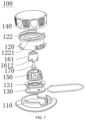
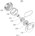
- 100-winding device 110-housing; 111-fourth clamping part; 120-fixing member; 121-through cavity; 122-elastic arm; 1221-check portion; 123-third clamping part; 124-second limiting portion; 125-first avoiding hole; 126-second avoiding hole; 130-reel; 131-toggle portion; 1311-first toothed edge; 132-first clamping part; 133-reel; 1331-first threading hole; 1332-second threading hole; 134-disk body; 140-knob; 141-linkage portion; 142-first clamping member; 143-mounting column; 1431-first mounting hole; 144-first limiting portion; 150-connecting member; 151-second clamping member; 152-stepped hole; 1521-guide groove; 1522-guide clamping structure; 15221-step-like structure; 152211-first step surface; 152212-second step surface; 153-second clamping part; 160-limiting component; 16
- the terms “mount”, “communicate”, “connect”, “fixe”, etc. are to be understood in a broad sense.
- it can be a fixed connection, a removable connection, or an integration; it can be a mechanical connection, an electrical connection, a direct connection, an indirect connection through an intermediate medium; and it can be a communication within two elements, or an interaction between two elements.
- the specific meaning of the above terms in the present disclosure can be understood on a case-by-case basis.
- first and second are used for descriptive purposes only and are cannot be understood as indicating or implying relative importance or implicitly specifying the number of technical features indicated.
- a feature defined as “first” or “second” can expressly or implicitly include one or more such features.
- “multiple” means two or more, unless otherwise expressly and specifically limited exist.
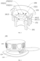
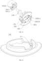
- embodiments of the present disclosure provide a winding device 100, which is mainly used in household items such as shoes, bags, and clothes that have cords that need to be wound or released, wherein the winding device 100 comprises a housing 110, a fixing member 120, a reel 130 for winding the cords, a knob 140, a connecting member 150, a limiting component 160, and a fastener 170.
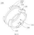
- the fixing member 120 is connected to the housing 110, wherein the way of connection can be snapping connection, the fixing member 120 is provided with through cavity 121 with openings at both ends, the elastic arm 122 is provided at one end of the fixing member 120 away from the housing 110, and the check portion 1221 is provided on the circumferential edge of the elastic arm 122.
- the reel 130 is rotatable in the through cavity 121 and disposed in the axial direction, and a toggle portion 131 is provided at the end of the reel 130 away from the housing 110.
- a linkage portion 141 and a first clamping part 142 are provided on the side of the knob 140 facing the fixing part 120, wherein the linkage portion 141 cooperates with the check portion 1221.
- the connecting member 150 is connected to the end of the reel 130 away from the housing 110, wherein the way of connection can be a snapping connection, such that the reel 130 and the connecting member 150 can rotate synchronously.
- the outer circumference of the connecting member 150 is provided with the second clamping member 151 cooperating with the first clamping member 142.
- the check portion 1221 can be a pawl
- the linkage portion 141 can be an oblique tooth groove 16121 that is capable of engaging with the pawl.
- the housing 110 can be secured to the tongue of the shoe by rivets and can also be attached to a bag or clothing.
- the first clamping member 142 is of a protruding structure and the second clamping member 151 is of a slot structure. When the first clamping member 142 is engaged with the second clamping member 151, the knob 140 rotates to drive the connecting member 150 and the reel 130 to synchronously rotate, and the knob 140 can be rotated in one of a counterclockwise or a clockwise direction, but cannot be bi-directionally rotated in a clockwise or a counterclockwise direction.
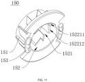
- the limiting component 160 comprises a guide member 161 and an elastic member, a stepped hole 152 is provided at the inner periphery of the connecting member 150, and the end of the guide member 161 close to the housing 110 is provided with a cooperation portion 1611 that matches the toggle portion 131.
- Multiple guide grooves 1521 are circumferentially defined and formed along the inner wall of the hole with the largest aperture of the stepped hole 152, wherein a guide clamping structure 1522 is formed between two adjacent guide grooves 1521 respectively.
- the elastic member abuts between the fixing member 120 and the knob 140, and the guide member 161 is movably disposed through the stepped hole 152.
- a clamping slider 1612 is provided along the circumferential direction of the guide member 161, wherein the clamping slider 1612 is capable of sliding inside the guide grooves 1521 and is capable of snapping with the guide clamping structure 1522.
- the fastener 170 passes through the guide member 161 to connect to the knob 140, such that guide member 161 is axially fixed to knob 140 and can be rotated circumferentially.
- the clamping slider 1612 slides out of the guide groove 1521 and the cooperation portion 1611 abuts against the toggle portion 131 to rotate the guide member 161 within the stepped hole 152 under the action of the toggle portion 131, such that the clamping slider 1612 is snapped with the guide clamping structure 1522 and the first clamping member 142 is snapped with the second clamping member 151, at which point the elastic member is compressed.
- the knob 140 is pressed again to rotate the guide member 161 within the stepped hole 152 under the action of the toggle portion 131.
- the initial position is the elastic state of the elastic member before the knob 140 is pressed for the first time.
- the embodiment of the present disclosure provides a winding device 100, in the course of use, for example, when tightening a cord, it only needs to press the knob 140 once to squeeze and drive the guide member 161 to move synchronously to make the clamping slider 1612 slide out of the guide groove 1521, and to make the cooperation portion 1611 to be engaged with the toggle portion 131 to rotate the guide member 161 inside the stepped hole 152 by the action of the toggle portion 131, so as to make the clamping slider 1612 to snap with the guide clamping structure 1522.
- the first clamping member 142 is snapped with the second clamping member 151, at which time, the elastic member is compressed, such that the linkage portion 141 is snapped with the check portion 1221 to enable the knob 140 to be rotated only in one of a clockwise direction or a counterclockwise direction, such as enabling the knob 140 to be rotated only in a clockwise direction, in this way, the knob 140 can drive the reel 130 to rotate to realize tightening of the cord.
- the knob 140 When the cord needs to be released, on the basis of the first pressing of the knob 140, the knob 140 is pressed again, the cooperation portion 1611 abuts against the toggle portion 131 in order to rotate the guide member 161 in the stepped hole 152 under the action of the toggle portion 131, and at the same time, by utilizing the reset elasticity generated by the elastic member being compressed, the clamping slider 1612 slides from the clamping structure to the guide groove 1521, and the first clamping member 142 is separated from the second clamping member 151, at which time the elastic member will be reset, and the linkage portion 141 abuts against the check portion 1221.
- the linkage portion 141 and the check portion 1221 can also be separated from each other.
- the reel 130 can be freely rotated in the clockwise or counterclockwise direction, and the cord can be released from the reel 130.
- the loosening and tightening of the cord can be realized by sequentially cyclically operating the knob 140, that is, the rotation and tightening of the cord can be realized by pressing the knob 140.
- the operation is simple and convenient, and the technical problem of difficult operation caused by pulling up the knob in the prior art is avoided.
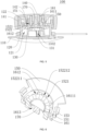
- a plurality of oblique teeth 16121 are provided at intervals along the circumferential direction of the guide member 161, the plurality of oblique teeth 16121 form the clamping slider 1612, the toggle portion 131 is provided with a first toothed edge 1311, and the cooperation portion 1611 is provided with a second toothed edge 16111 that mates with the first toothed edge 1311.
- the first clamping member 142 is snapped with the second clamping member 151, at which time the elastic member is compressed, and the linkage portion 141 is snapped to the check portion 1221, such that the knob 140 can drive the reel 130 to rotate to realize tightening of the cord.
- the knob 140 When the cord needs to be released, on the basis of the first pressing of the knob 140, the knob 140 is pressed again, and the second toothed edge 16111 abuts against the first toothed edge 1311 so as to rotate the guide member 161 within the stepped hole 152 under the action of the first toothed edge 1311, and at the same time, by using the reset elasticity generated by the compression of the elastic member, the oblique teeth 16121 slide from the clamping structure to the guide groove 1521.
- the first clamping member 142 is separated from the second clamping member 151, at which time the elastic member is reset, and the linkage portion 141 is snapped with the check portion 1221.
- the linkage portion 141 and the check portion 1221 can also be separated, and the reel 130 can freely rotate in either a clockwise or a counterclockwise direction, and the cord can be released from the reel 130.
- the guide clamping structure 1522 is a step-like structure 15221, and the step-like structure 15221 comprises a first step surface 152211 and a second step surface 152212, wherein the first step surface 152211 and the second step surface 152212 are inclined surfaces and are in the same inclined direction, respectively, as the inclined teeth 16121.
- the knob 140 when the knob 140 is pressed, the knob 140 pushes the oblique teeth 16121 down along the guide groove 1521 to the junction of the guide groove 1521 and the second step surface 152212, at which time the elastic member is compressed to generate an elastic force.
- the oblique teeth 16121 move from the junction of the guide groove 1521 and the second step surface 152212 to a position where the second step surface 152212 is close to the first step surface 152211, and is snapped to the position of the second step surface 152212 close to the first step surface 152211, with the elastic member still in a compressed state.
- the knob 140 pushes the oblique teeth 16121 downwardly along the interface between the second step surface 152212 and the first step surface 152211 to the junction of the first step surface 152211 and the second step surface 152212, and the elastic member is still in the state of compression.
- the oblique teeth 16121 move from the junction of the first step surface 152211 and the second step surface 152212 to the first step surface 152211, and move along the first step surface 152211 to the guide groove 1521 to return to the initial position.
- the first toothed edge 1311 and the reel 130 are made by integral injection molding.
- integral injection molding of the first toothed edge 1311 and the reel 130 this not only improves the stability of the connection between the toggle portion 131 and the reel 130, but also makes the structure compact, thereby improving the utilization of space, and being conducive to reducing the overall thickness of the winding device 100.
- integral injection molding further eliminates the installation step of mounting the toggle portion 131 to the reel 130, thereby improving the overall installation efficiency of the winding device 100.
- the reel 130 is provided with a first clamping part 132 at the end of the reel away from the housing 110, and the end of the connecting member 150 close to the housing 110 is provided with a second clamping part 153 that engages with the first clamping part 132.
- the reel 130 and the connecting member 150 are fixedly connected as a whole. Therefore, the reel 130 and the connecting member 150 can be synchronously and stably rotated.
- the first clamping part 132 can be a snap-fit
- the second clamping part 153 can be a groove that fits to the snap-fit
- the first clamping part 132 can be a groove
- the second clamping part 153 can be a snap-fit that fits to the groove.
- the fixing member 120 is provided with a third clamping part 123 at an end close to the housing 110, and the housing 110 is provided with a fourth clamping part 111 that is snapped to the third clamping part 123.
- the fixing member 120 is mounted stably on the housing 110, thereby realizing the function of solidly mounting the fixing member 120.
- the third clamping part 123 can be a snap-fit
- the fourth clamping part 111 can be a groove that fits to the snap-fit
- the third clamping part 123 can be a groove and the fourth clamping part 111 can be a snap-fit that fits to the groove.
- the elastic arm 122 and the fixing member 120 are made by integral injection molding.
- integral injection molding of the elastic arm 122 and the fixing member 120 this not only can improve the stability of the connection between the elastic arm 122 and the fixing member 120, but also makes the structure compact, thereby improving the utilization of space, and being conducive to reducing the overall thickness of the winding device 100.
- integral injection molding can eliminate the installation step of mounting the elastic arm 122 on the fixing member 120, thereby improving the overall installation efficiency of the winding device 100.
- the knob 140 is provided with a mounting column 143 protruding from the side of the knob 140 close to the housing 110, wherein the mounting column 143 is provided with a first mounting hole 1431, and the guide member 161 is provided with a second mounting hole 1613, and the fastener 170 is sequentially passed through the second mounting hole 1613 and the first mounting hole 1431, so as to tightly connect the guide member 161 to the knob 140.
- the mounting column 143 is provided by protruding from the side of the knob 140 near the housing 110, a first mounting hole 1431 is provided on the mounting column 143, and a second mounting hole 1613 is provided on the guide member 161, such that the fastener 170 can be passed through the second mounting hole 1613 and the first mounting hole 1431 in sequence, so that the guide member 161 is tightly connected to the knob 140, and thereby the guide member 161 is axially fixed to the knob 140 and can be rotated circumferentially.
- the fastener 170 can be screws
- the first mounting hole 1431 can be screw hole that fits to the screw
- the second mounting hole 1613 can be stepped mounting hole.
- the knob 140 is provided with a first limiting portion 144 on the inner circumference of one end close to the housing 110, and the second limiting portion 124 matched with the first limiting portion 144 is provided at the outer circumference of one end of the fixing member 120 away from the housing 110.
- the first limiting portion 144 is provided on the inner circumference of the end of the knob 140 close to the housing 110, and the second limiting portion 124 cooperating with the first limiting portion 144 is provided on the outer circumference of the end of the fixing member 120 away from the housing 110, so as to play a role in limiting the position of the knob 140, thereby preventing the knob 140 from falling off from the fixing member 120.
- the first limiting portion 144 can be a limiting clasp
- the second limiting portion 124 can be an annular projection that cooperates with the limiting clasp.
- the reel 130 comprises a reel 133 and a disk body 134 disposed at both ends of the reel 133, wherein the disk body 134 has a diameter greater than the diameter of the reel 133.
- the reel 133 is respectively provided with a first threading hole 1331 and a second threading hole 1332 along the direction perpendicular to the axis of reel 133.
- the fixing member 120 is provided with a first avoidance hole 125 and a second avoidance hole 126, wherein the first avoidance hole 125 is provided correspondingly to the first threading hole 1331, and the second avoidance hole 126 is provided correspondingly to the second threading hole 1332.
- one end of the cord can be sequentially passed through the first avoidance hole 125 and the first threading hole 1331 to be knotted and fixed within the reel 130, and the other end of the cord can be sequentially passed through the second avoidance hole 126 and the second threading hole 1332 to be knotted and fixed within the reel 130.
- the present disclosure proposes a winding device 100, wherein the winding device 100 comprises a housing 110, a fixing member 120, a reel 130 for winding the cord, a knob 140, a connecting member 150, a limiting component 160 and a fastener 170, wherein the limiting component 160 comprises a guide member 161 and an elastic member, and the fixing member 120 is connected to the housing 110 and is provided with a through cavity 121 with openings at both ends.
- An elastic arm 122 is provided at one end of the fixing member 120 away from the housing 110, and a check portion 1221 is provided at the circumferential edge of the elastic arm 122.
- the reel 130 is rotatable in the axial direction and disposed in the through cavity 121, and a toggle portion 131 is provided at one end of the reel 130 away from the housing 110.
- the side of the knob 140 facing the fixing member 120 is provided with a first clamping member 142 and a linkage portion 141 that cooperates with the check portion 1221.
- the connecting member 150 is connected to the end of the reel 130 away from the housing 110, wherein the outer periphery of the connecting member 150 is provided with a second clamping member 151 matching with the first clamping member 142, and a stepped hole 152 is provided in the inner periphery of the connecting member 150.
- An end of the guide member 161 close to the housing 110 is provided with a cooperation portion 1611 that matches with the toggle portion 131, and multiple guide grooves 1521 are circumferentially defined and formed along the inner wall of the hole with the largest aperture of the stepped hole 152.
- a guide clamping structure 1522 is formed between two adjacent guide grooves 1521.
- the elastic member abuts between the fixing member 120 and the knob 140.
- the guide member 161 is movably passed through the stepped hole 152, clamping slider 1612 is provided along the circumferential direction of the guide member 161, and the fastener 170 is passed through the guide member 161 to connect to the knob 140.
- the elastic member is compressed, and the linkage portion 141 is snapped with the check portion 1221, such that the knob 140 can only rotate in one of the clockwise direction or the counterclockwise direction, for example, the knob 140 can only rotate in the clockwise direction.
- the knob 140 can drive the reel 130 to rotate to tighten the cord. If it is necessary to release the cord, on the basis of the first pressing of the knob 140, the knob 140 is pressed again, and the cooperation portion 1611 abuts against the toggle portion 131, so as to rotate the guide member 161 in the stepped hole 152 under the action of the toggle portion 131.
- the clamping slider 1612 is slid from the clamping structure into the guide groove 1521, and the first clamping member 142 is separated from the second clamping member 151.
- the elastic member is reset, the linkage portion 141 is engaged with the check portion 1221, the reel 130 can rotate freely in the clockwise or counterclockwise direction, and the cord can be loosened from the reel 130.
- the cord can be tightened or loosened by sequentially cyclically operating and pressing the knob 140, that is, by pressing the knob 140, the cord can be rotated and tightened.
- the operation is simple and convenient, and avoids the technical difficulty in operation caused by pulling up the knob in the prior art.
Landscapes
- Storing, Repeated Paying-Out, And Re-Storing Of Elongated Articles (AREA)
- Footwear And Its Accessory, Manufacturing Method And Apparatuses (AREA)
- Clamps And Clips (AREA)
Claims (10)
- Eine Wickelvorrichtung (100), die Folgendes umfasst:ein Gehäuse (110);ein Befestigungselement (120), das mit dem Gehäuse (110) verbunden ist, wobei das Befestigungselement (120) mit einem durchgehenden Hohlraum (121) mit zwei Öffnungen an beiden Enden versehen ist, wobei ein elastischer Arm (122) an einem vom Gehäuse (110) entfernten Ende des Befestigungselements (120) vorgesehen ist, und ein Umfangsrand des elastischen Arms (122) mit einem Sperrabschnitt (1221) versehen ist;eine Spule (130) zum Aufwickeln einer Schnur, wobei die Spule (130) in einer axialen Richtung drehbar ist und in dem durchgehenden Hohlraum (121) vorgesehen ist, und ein Knebelteil (131) an einem Ende der Spule (130) weg von dem Gehäuse (110) vorgesehen ist;einen Knopf (140), wobei ein Verbindungsabschnitt (141) und ein erstes Klemmelement (142) auf einer Seite des Knopfes (140) in Richtung des Befestigungselements (120) vorgesehen ist, und der Verbindungsabschnitt (141) mit dem Prüfabschnitt (1221) zusammenwirkt;ein Verbindungselement (150), das mit dem vom Gehäuse (110) abgewandten Ende der Spule (130) verbunden ist, wobei ein Außenumfang des Verbindungselements (150) mit einem zweiten Klemmelement (151) versehen ist, das zu dem ersten Klemmelement (142) passt; dadurch gekennzeichnet, dass es ferner Folgendes umfassteine Begrenzungskomponente (160), wobei die Begrenzungskomponente (160) ein Führungselement (161) und ein elastisches Element umfasst; ein abgestuftes Loch (152) an einem Innenumfang des Verbindungselements (150) vorgesehen ist; ein Ende des Führungselements (161) nahe dem Gehäuse (110) mit einem Kooperationsabschnitt (1611) versehen ist, der zu dem Knebelteil (131) passt; mehrere Führungsnuten (1521) entlang einer Umfangsrichtung einer Innenwand eines Lochs mit einer größten Öffnung des abgestuften Lochs (152) definiert und ausgebildet sind und eine Führungsklemmstruktur (1522) zwischen zwei benachbarten Führungsnuten (1521) ausgebildet ist, wobei das elastische Element zwischen dem Befestigungselement (120) und dem Knopf (140) anliegt, das Führungselement (161) beweglich durch das gestufte Loch (152) geführt wird und ein Klemmschieber (1612) entlang einer Umfangsrichtung des Führungselements (161) vorgesehen ist; undein Befestigungselement (170), wobei das Befestigungselement (170) durch das Führungselement (161) geführt wird, um mit dem Knopf (140) verbunden zu werden, wobeiwenn der Knopf (140) gedrückt wird, gleitet der Klemmschieber (1612) aus der Führungsnut (1521) heraus, und der Kooperationsabschnitt (1611) stößt gegen das Knebelteil (131), um das Führungselement (161) innerhalb des gestuften Lochs (152) unter der Wirkung des Knebelteils (131) zu drehen, so dass der Klemmschieber (1612) mit der Führungsklemmstruktur (1522) in Eingriff kommt und das erste Klemmelement (142) mit dem zweiten Klemmelement (151) in Eingriff kommt; und der Knopf (140) erneut gedrückt wird, um das Führungselement (161) innerhalb des gestuften Lochs (152) unter der Wirkung des Knebelteils (131) zu drehen, so dass der Klemmschieber (1612) von der Klemmstruktur in die Führungsnut (1521) gleitet und das erste Klemmelement (142) von dem zweiten Klemmelement (151) getrennt wird.
- . Wickelvorrichtung (100) nach Anspruch 1, wobei mehrere schräge Zähne in Abständen entlang der Umfangsrichtung des Führungselements (161) vorgesehen sind, die mehreren schrägen Zähne den Klemmschieber (1612) bilden, der Knebelteil (131) mit einer ersten gezahnten Kante (1311) versehen ist, und der Kooperationsabschnitt (1611) mit einer zweiten gezahnten Kante (16111) versehen ist, die mit der ersten gezahnten Kante (1311) zusammenpasst.
- . Wickelvorrichtung (100) nach Anspruch 2, wobei die Führungsklemmstruktur (1522) eine stufenartige Struktur (15221) ist, die stufenartige Struktur (15221) eine erste gestufte Oberfläche und eine zweite gestufte Oberfläche umfasst und die erste gestufte Oberfläche und die zweite gestufte Oberfläche geneigte Oberflächen sind und jeweils in der gleichen geneigten Richtung wie die schrägen Zähne liegen.
- . Wickelvorrichtung (100) nach Anspruch 2, wobei die erste Zahnkante (1311) und die Spule (130) durch integrales Spritzgießen hergestellt sind.
- . Wickelvorrichtung (100) nach Anspruch 1, wobei die Spule (130) an dem dem Gehäuse (110) abgewandten Ende mit einem ersten Klemmteil (132) versehen ist und ein dem Gehäuse (110) nahes Ende des Verbindungselements (150) mit einem zweiten Klemmteil (153) versehen ist, das mit dem ersten Klemmteil (132) verrastet ist.
- . Wickelvorrichtung (100) nach Anspruch 1, wobei das Befestigungselement (120) an einem Ende nahe dem Gehäuse (110) mit einem dritten Klemmteil (123) versehen ist und das Gehäuse (110) mit einem vierten Klemmteil (111) versehen ist, das mit dem dritten Klemmteil (123) verrastet ist.
- . Wickelvorrichtung (100) nach Anspruch 1, wobei der elastische Arm (122) und das Befestigungselement (120) durch integrales Spritzgießen hergestellt sind.
- . Wickelvorrichtung (100) nach Anspruch 1, wobei der Knopf (140) mit einer Befestigungssäule (143) versehen ist, die von einer Seite des Knopfes (140) nahe dem Gehäuse (110) vorsteht, wobei die Befestigungssäule (143) mit einem ersten Befestigungsloch (1431) versehen ist, das Führungselement (161) mit einem zweiten Montageloch (1613) versehen ist, und das Befestigungselement (170) nacheinander durch das zweite Montageloch (1613) und das erste Montageloch (1431) geführt wird, um das Führungselement (161) fest mit dem Knopf (140) zu verbinden.
- . Wickelvorrichtung (100) nach Anspruch 1, wobei ein erster Begrenzungsabschnitt (144) an einem Innenumfang eines Endes des Knopfes (140) nahe dem Gehäuse (110) vorgesehen ist, ein zweiter Begrenzungsabschnitt (124), der mit dem ersten Begrenzungsabschnitt (144) zusammenwirkt, an einem Außenumfang eines Endes des Befestigungselements (120) entfernt vom Gehäuse (110) vorgesehen ist.
- . Wickelvorrichtung (100) nach einem der Ansprüche 1 bis 9, wobei die Spule (130) eine Rolle (133) und einen Scheibenkörper (134) umfasst, der an beiden Enden der Rolle (133) vorgesehen ist, ein Durchmesser des Scheibenkörpers (134) größer ist als ein Durchmesser der Rolle (133), die Rolle (133) jeweils mit einem ersten Einfädelloch (1331) und einem zweiten Einfädelloch (1332) entlang einer Richtung senkrecht zu einer Achse der Rolle (133) versehen ist, und das Befestigungselement (120) mit einem ersten Umgehungsloch und einem zweiten Umgehungsloch versehen ist, wobei das erste Umgehungsloch entsprechend dem ersten Gewindeloch (1331) vorgesehen ist und das zweite Umgehungsloch entsprechend dem zweiten Gewindeloch (1332) vorgesehen ist.
Applications Claiming Priority (2)
| Application Number | Priority Date | Filing Date | Title |
|---|---|---|---|
| CN202321926390.6U CN220364187U (zh) | 2023-07-21 | 2023-07-21 | 一种收线器 |
| CN202310898727.5A CN116924162A (zh) | 2023-07-21 | 2023-07-21 | 一种收线器 |
Publications (3)
| Publication Number | Publication Date |
|---|---|
| EP4494513A1 EP4494513A1 (de) | 2025-01-22 |
| EP4494513C0 EP4494513C0 (de) | 2025-05-28 |
| EP4494513B1 true EP4494513B1 (de) | 2025-05-28 |
Family
ID=89474265
Family Applications (1)
| Application Number | Title | Priority Date | Filing Date |
|---|---|---|---|
| EP24150153.5A Active EP4494513B1 (de) | 2023-07-21 | 2024-01-03 | Wickelvorrichtung |
Country Status (3)
| Country | Link |
|---|---|
| US (1) | US20250024919A1 (de) |
| EP (1) | EP4494513B1 (de) |
| WO (1) | WO2025020336A1 (de) |
Families Citing this family (1)
| Publication number | Priority date | Publication date | Assignee | Title |
|---|---|---|---|---|
| CN116965617A (zh) * | 2023-07-13 | 2023-10-31 | 泉州振科技术服务有限公司 | 一种防掰爪绳物收放装置及鞋 |
Family Cites Families (7)
| Publication number | Priority date | Publication date | Assignee | Title |
|---|---|---|---|---|
| US7584528B2 (en) * | 2007-02-20 | 2009-09-08 | Meng Hann Plastic Co., Ltd. | Shoelace reel operated easily and conveniently |
| JP7303277B2 (ja) * | 2019-10-15 | 2023-07-04 | 金柱 陳 | ひも締緩装置 |
| CN112789233A (zh) * | 2021-01-08 | 2021-05-11 | 叶世峰 | 绳线收放装置、鞋子、帽子、手套及收纳装置 |
| CN114291666B (zh) * | 2021-12-30 | 2024-06-07 | 深圳市悠宁科技有限公司 | 一种收放线装置 |
| CN114735548B (zh) * | 2022-04-25 | 2025-07-25 | 深圳市悠宁科技有限公司 | 一种收线器及具有其的物品 |
| CN218960176U (zh) * | 2022-12-22 | 2023-05-05 | 深圳市悠宁科技有限公司 | 绳索收放装置及具有绳索收放装置的物品 |
| CN116924162A (zh) * | 2023-07-21 | 2023-10-24 | 深圳市悠宁科技有限公司 | 一种收线器 |
-
2023
- 2023-10-31 WO PCT/CN2023/128629 patent/WO2025020336A1/zh active Pending
-
2024
- 2024-01-03 EP EP24150153.5A patent/EP4494513B1/de active Active
- 2024-01-18 US US18/416,272 patent/US20250024919A1/en active Pending
Also Published As
| Publication number | Publication date |
|---|---|
| US20250024919A1 (en) | 2025-01-23 |
| EP4494513A1 (de) | 2025-01-22 |
| WO2025020336A1 (zh) | 2025-01-30 |
| EP4494513C0 (de) | 2025-05-28 |
Similar Documents
| Publication | Publication Date | Title |
|---|---|---|
| US11457698B2 (en) | Integrated closure device components and methods | |
| CN114735548A (zh) | 一种收线器及具有其的物品 | |
| US11849810B2 (en) | Fastening device | |
| US11751634B2 (en) | Fastening device and lace assembling method | |
| US20230337787A1 (en) | Fastening device | |
| US6564671B2 (en) | Switch style bicycle shift control device | |
| EP4494513B1 (de) | Wickelvorrichtung | |
| US20190150569A1 (en) | Fastening device and lace assembling method thereof | |
| KR102385710B1 (ko) | 끈 조임 장치 및 끈을 구비한 제품 | |
| CN218960176U (zh) | 绳索收放装置及具有绳索收放装置的物品 | |
| CN217051142U (zh) | 一种收线器及具有其的物品 | |
| US12336597B2 (en) | Fastening device | |
| US12108843B2 (en) | Fastening device | |
| CN116924162A (zh) | 一种收线器 | |
| CN218978168U (zh) | 线绳调节装置及具有线绳调节装置的物品 | |
| CN220364187U (zh) | 一种收线器 | |
| CN221343447U (zh) | 一种收线器及具有其的物品 | |
| WO2023206908A1 (zh) | 一种收线器及具有其的物品 | |
| CN116715100A (zh) | 一种收放线装置 | |
| CN116831358B (zh) | 线绳调节装置及具有线绳调节装置的物品 | |
| CN116509107A (zh) | 绳带调节装置、碳棒鞋、绑带鞋以及背包 | |
| CN108685270B (zh) | 一种基于转子和定子的系带系统及其使用方法 | |
| CN117509332A (zh) | 一种收线器及具有其的物品 | |
| JP2639894B2 (ja) | 紐調節用固定具 | |
| EP4144250A1 (de) | Rotierende zug-druck-seilaufroller und schuhe |
Legal Events
| Date | Code | Title | Description |
|---|---|---|---|
| PUAI | Public reference made under article 153(3) epc to a published international application that has entered the european phase |
Free format text: ORIGINAL CODE: 0009012 |
|
| STAA | Information on the status of an ep patent application or granted ep patent |
Free format text: STATUS: REQUEST FOR EXAMINATION WAS MADE |
|
| 17P | Request for examination filed |
Effective date: 20240103 |
|
| AK | Designated contracting states |
Kind code of ref document: A1 Designated state(s): AL AT BE BG CH CY CZ DE DK EE ES FI FR GB GR HR HU IE IS IT LI LT LU LV MC ME MK MT NL NO PL PT RO RS SE SI SK SM TR |
|
| GRAP | Despatch of communication of intention to grant a patent |
Free format text: ORIGINAL CODE: EPIDOSNIGR1 |
|
| STAA | Information on the status of an ep patent application or granted ep patent |
Free format text: STATUS: GRANT OF PATENT IS INTENDED |
|
| INTG | Intention to grant announced |
Effective date: 20250218 |
|
| GRAS | Grant fee paid |
Free format text: ORIGINAL CODE: EPIDOSNIGR3 |
|
| GRAA | (expected) grant |
Free format text: ORIGINAL CODE: 0009210 |
|
| STAA | Information on the status of an ep patent application or granted ep patent |
Free format text: STATUS: THE PATENT HAS BEEN GRANTED |
|
| AK | Designated contracting states |
Kind code of ref document: B1 Designated state(s): AL AT BE BG CH CY CZ DE DK EE ES FI FR GB GR HR HU IE IS IT LI LT LU LV MC ME MK MT NL NO PL PT RO RS SE SI SK SM TR |
|
| REG | Reference to a national code |
Ref country code: GB Ref legal event code: FG4D |
|
| REG | Reference to a national code |
Ref country code: CH Ref legal event code: EP |
|
| REG | Reference to a national code |
Ref country code: IE Ref legal event code: FG4D Ref country code: DE Ref legal event code: R096 Ref document number: 602024000147 Country of ref document: DE |
|
| U01 | Request for unitary effect filed |
Effective date: 20250616 |
|
| U07 | Unitary effect registered |
Designated state(s): AT BE BG DE DK EE FI FR IT LT LU LV MT NL PT RO SE SI Effective date: 20250626 |
|
| PG25 | Lapsed in a contracting state [announced via postgrant information from national office to epo] |
Ref country code: ES Free format text: LAPSE BECAUSE OF FAILURE TO SUBMIT A TRANSLATION OF THE DESCRIPTION OR TO PAY THE FEE WITHIN THE PRESCRIBED TIME-LIMIT Effective date: 20250528 |
|
| PG25 | Lapsed in a contracting state [announced via postgrant information from national office to epo] |
Ref country code: NO Free format text: LAPSE BECAUSE OF FAILURE TO SUBMIT A TRANSLATION OF THE DESCRIPTION OR TO PAY THE FEE WITHIN THE PRESCRIBED TIME-LIMIT Effective date: 20250828 Ref country code: GR Free format text: LAPSE BECAUSE OF FAILURE TO SUBMIT A TRANSLATION OF THE DESCRIPTION OR TO PAY THE FEE WITHIN THE PRESCRIBED TIME-LIMIT Effective date: 20250829 |
|
| PG25 | Lapsed in a contracting state [announced via postgrant information from national office to epo] |
Ref country code: PL Free format text: LAPSE BECAUSE OF FAILURE TO SUBMIT A TRANSLATION OF THE DESCRIPTION OR TO PAY THE FEE WITHIN THE PRESCRIBED TIME-LIMIT Effective date: 20250528 |
|
| PG25 | Lapsed in a contracting state [announced via postgrant information from national office to epo] |
Ref country code: HR Free format text: LAPSE BECAUSE OF FAILURE TO SUBMIT A TRANSLATION OF THE DESCRIPTION OR TO PAY THE FEE WITHIN THE PRESCRIBED TIME-LIMIT Effective date: 20250528 |
|
| PG25 | Lapsed in a contracting state [announced via postgrant information from national office to epo] |
Ref country code: RS Free format text: LAPSE BECAUSE OF FAILURE TO SUBMIT A TRANSLATION OF THE DESCRIPTION OR TO PAY THE FEE WITHIN THE PRESCRIBED TIME-LIMIT Effective date: 20250828 |
|
| PG25 | Lapsed in a contracting state [announced via postgrant information from national office to epo] |
Ref country code: IS Free format text: LAPSE BECAUSE OF FAILURE TO SUBMIT A TRANSLATION OF THE DESCRIPTION OR TO PAY THE FEE WITHIN THE PRESCRIBED TIME-LIMIT Effective date: 20250928 |
|
| PG25 | Lapsed in a contracting state [announced via postgrant information from national office to epo] |
Ref country code: SM Free format text: LAPSE BECAUSE OF FAILURE TO SUBMIT A TRANSLATION OF THE DESCRIPTION OR TO PAY THE FEE WITHIN THE PRESCRIBED TIME-LIMIT Effective date: 20250528 |
|
| PG25 | Lapsed in a contracting state [announced via postgrant information from national office to epo] |
Ref country code: CZ Free format text: LAPSE BECAUSE OF FAILURE TO SUBMIT A TRANSLATION OF THE DESCRIPTION OR TO PAY THE FEE WITHIN THE PRESCRIBED TIME-LIMIT Effective date: 20250528 |
|
| PG25 | Lapsed in a contracting state [announced via postgrant information from national office to epo] |
Ref country code: SK Free format text: LAPSE BECAUSE OF FAILURE TO SUBMIT A TRANSLATION OF THE DESCRIPTION OR TO PAY THE FEE WITHIN THE PRESCRIBED TIME-LIMIT Effective date: 20250528 |
|
| U20 | Renewal fee for the european patent with unitary effect paid |
Year of fee payment: 3 Effective date: 20260129 |