EP4492012A1 - Magnetische jochanordnung und sensorvorrichtung - Google Patents
Magnetische jochanordnung und sensorvorrichtung Download PDFInfo
- Publication number
- EP4492012A1 EP4492012A1 EP22930937.2A EP22930937A EP4492012A1 EP 4492012 A1 EP4492012 A1 EP 4492012A1 EP 22930937 A EP22930937 A EP 22930937A EP 4492012 A1 EP4492012 A1 EP 4492012A1
- Authority
- EP
- European Patent Office
- Prior art keywords
- collar
- holder
- shaft
- yoke assembly
- magnetic yoke
- Prior art date
- Legal status (The legal status is an assumption and is not a legal conclusion. Google has not performed a legal analysis and makes no representation as to the accuracy of the status listed.)
- Pending
Links
Images


Classifications
-
- G—PHYSICS
- G01—MEASURING; TESTING
- G01L—MEASURING FORCE, STRESS, TORQUE, WORK, MECHANICAL POWER, MECHANICAL EFFICIENCY, OR FLUID PRESSURE
- G01L3/00—Measuring torque, work, mechanical power, or mechanical efficiency, in general
- G01L3/02—Rotary-transmission dynamometers
- G01L3/04—Rotary-transmission dynamometers wherein the torque-transmitting element comprises a torsionally-flexible shaft
- G01L3/10—Rotary-transmission dynamometers wherein the torque-transmitting element comprises a torsionally-flexible shaft involving electric or magnetic means for indicating
- G01L3/101—Rotary-transmission dynamometers wherein the torque-transmitting element comprises a torsionally-flexible shaft involving electric or magnetic means for indicating involving magnetic or electromagnetic means
-
- B—PERFORMING OPERATIONS; TRANSPORTING
- B62—LAND VEHICLES FOR TRAVELLING OTHERWISE THAN ON RAILS
- B62D—MOTOR VEHICLES; TRAILERS
- B62D6/00—Arrangements for automatically controlling steering depending on driving conditions sensed and responded to, e.g. control circuits
- B62D6/08—Arrangements for automatically controlling steering depending on driving conditions sensed and responded to, e.g. control circuits responsive only to driver input torque
- B62D6/10—Arrangements for automatically controlling steering depending on driving conditions sensed and responded to, e.g. control circuits responsive only to driver input torque characterised by means for sensing or determining torque
-
- B—PERFORMING OPERATIONS; TRANSPORTING
- B62—LAND VEHICLES FOR TRAVELLING OTHERWISE THAN ON RAILS
- B62D—MOTOR VEHICLES; TRAILERS
- B62D15/00—Steering not otherwise provided for
- B62D15/02—Steering position indicators ; Steering position determination; Steering aids
- B62D15/021—Determination of steering angle
- B62D15/0215—Determination of steering angle by measuring on the steering column
-
- G—PHYSICS
- G01—MEASURING; TESTING
- G01D—MEASURING NOT SPECIALLY ADAPTED FOR A SPECIFIC VARIABLE; ARRANGEMENTS FOR MEASURING TWO OR MORE VARIABLES NOT COVERED IN A SINGLE OTHER SUBCLASS; TARIFF METERING APPARATUS; MEASURING OR TESTING NOT OTHERWISE PROVIDED FOR
- G01D5/00—Mechanical means for transferring the output of a sensing member; Means for converting the output of a sensing member to another variable where the form or nature of the sensing member does not constrain the means for converting; Transducers not specially adapted for a specific variable
- G01D5/12—Mechanical means for transferring the output of a sensing member; Means for converting the output of a sensing member to another variable where the form or nature of the sensing member does not constrain the means for converting; Transducers not specially adapted for a specific variable using electric or magnetic means
- G01D5/14—Mechanical means for transferring the output of a sensing member; Means for converting the output of a sensing member to another variable where the form or nature of the sensing member does not constrain the means for converting; Transducers not specially adapted for a specific variable using electric or magnetic means influencing the magnitude of a current or voltage
- G01D5/142—Mechanical means for transferring the output of a sensing member; Means for converting the output of a sensing member to another variable where the form or nature of the sensing member does not constrain the means for converting; Transducers not specially adapted for a specific variable using electric or magnetic means influencing the magnitude of a current or voltage using Hall-effect devices
- G01D5/145—Mechanical means for transferring the output of a sensing member; Means for converting the output of a sensing member to another variable where the form or nature of the sensing member does not constrain the means for converting; Transducers not specially adapted for a specific variable using electric or magnetic means influencing the magnitude of a current or voltage using Hall-effect devices influenced by the relative movement between the Hall device and magnetic fields
-
- G—PHYSICS
- G01—MEASURING; TESTING
- G01L—MEASURING FORCE, STRESS, TORQUE, WORK, MECHANICAL POWER, MECHANICAL EFFICIENCY, OR FLUID PRESSURE
- G01L3/00—Measuring torque, work, mechanical power, or mechanical efficiency, in general
- G01L3/02—Rotary-transmission dynamometers
- G01L3/04—Rotary-transmission dynamometers wherein the torque-transmitting element comprises a torsionally-flexible shaft
- G01L3/10—Rotary-transmission dynamometers wherein the torque-transmitting element comprises a torsionally-flexible shaft involving electric or magnetic means for indicating
- G01L3/101—Rotary-transmission dynamometers wherein the torque-transmitting element comprises a torsionally-flexible shaft involving electric or magnetic means for indicating involving magnetic or electromagnetic means
- G01L3/104—Rotary-transmission dynamometers wherein the torque-transmitting element comprises a torsionally-flexible shaft involving electric or magnetic means for indicating involving magnetic or electromagnetic means involving permanent magnets
-
- G—PHYSICS
- G01—MEASURING; TESTING
- G01L—MEASURING FORCE, STRESS, TORQUE, WORK, MECHANICAL POWER, MECHANICAL EFFICIENCY, OR FLUID PRESSURE
- G01L5/00—Apparatus for, or methods of, measuring force, work, mechanical power, or torque, specially adapted for specific purposes
- G01L5/22—Apparatus for, or methods of, measuring force, work, mechanical power, or torque, specially adapted for specific purposes for measuring the force applied to control members, e.g. control members of vehicles, triggers
- G01L5/221—Apparatus for, or methods of, measuring force, work, mechanical power, or torque, specially adapted for specific purposes for measuring the force applied to control members, e.g. control members of vehicles, triggers to steering wheels, e.g. for power assisted steering
-
- G—PHYSICS
- G01—MEASURING; TESTING
- G01D—MEASURING NOT SPECIALLY ADAPTED FOR A SPECIFIC VARIABLE; ARRANGEMENTS FOR MEASURING TWO OR MORE VARIABLES NOT COVERED IN A SINGLE OTHER SUBCLASS; TARIFF METERING APPARATUS; MEASURING OR TESTING NOT OTHERWISE PROVIDED FOR
- G01D2205/00—Indexing scheme relating to details of means for transferring or converting the output of a sensing member
- G01D2205/20—Detecting rotary movement
- G01D2205/26—Details of encoders or position sensors specially adapted to detect rotation beyond a full turn of 360°, e.g. multi-rotation
-
- G—PHYSICS
- G01—MEASURING; TESTING
- G01D—MEASURING NOT SPECIALLY ADAPTED FOR A SPECIFIC VARIABLE; ARRANGEMENTS FOR MEASURING TWO OR MORE VARIABLES NOT COVERED IN A SINGLE OTHER SUBCLASS; TARIFF METERING APPARATUS; MEASURING OR TESTING NOT OTHERWISE PROVIDED FOR
- G01D2205/00—Indexing scheme relating to details of means for transferring or converting the output of a sensing member
- G01D2205/20—Detecting rotary movement
- G01D2205/28—The target being driven in rotation by additional gears
-
- G—PHYSICS
- G01—MEASURING; TESTING
- G01D—MEASURING NOT SPECIALLY ADAPTED FOR A SPECIFIC VARIABLE; ARRANGEMENTS FOR MEASURING TWO OR MORE VARIABLES NOT COVERED IN A SINGLE OTHER SUBCLASS; TARIFF METERING APPARATUS; MEASURING OR TESTING NOT OTHERWISE PROVIDED FOR
- G01D2205/00—Indexing scheme relating to details of means for transferring or converting the output of a sensing member
- G01D2205/40—Position sensors comprising arrangements for concentrating or redirecting magnetic flux
-
- H—ELECTRICITY
- H01—ELECTRIC ELEMENTS
- H01F—MAGNETS; INDUCTANCES; TRANSFORMERS; SELECTION OF MATERIALS FOR THEIR MAGNETIC PROPERTIES
- H01F3/00—Cores, Yokes, or armatures
Definitions
- the present disclosure relates to magnetic yoke assemblies and sensor devices.
- Patent Document 1 a sensor device that is used in a steering device is conventionally known in the art.
- This sensor device is provided on the outer periphery of a steering shaft to which a steering wheel is connected, and detects both steering torque input by a driver and a steering angle that is a rotation angle of the steering shaft.
- the steering shaft includes an input shaft, an output shaft, and a torsion bar that connects the input shaft and the output shaft to each other.
- the sensor device includes a sensor magnet fixed to the input shaft, a magnetic yoke assembly fixed to the output shaft, and driven gears that rotate in response to rotation of the magnetic yoke assembly. The sensor device detects the steering torque based on the magnetic flux flowing through the magnetic yoke assembly, and detects the steering angle based on the rotation angles of the driven gears.
- such a magnetic yoke assembly includes a pair of yoke cores, an annular collar, and a tubular resin holder that holds the yoke cores and the collar.
- the collar is held at one axial end of the resin holder, and a gear portion that meshes with the driven gears is provided on the outer peripheral surface of the other axial end thereof.
- the magnetic yoke assembly includes a pair of yoke cores, an annular collar, and a tubular holder that holds the pair of yoke cores and the collar.
- the holder includes a gear portion that includes a plurality of external teeth protruding radially outward from the holder.
- the collar is disposed at an inner periphery of the gear portion. An axial range in which the collar is present in the holder overlaps an axial range in which the gear portion is provided in the holder.
- the sensor device includes: a sensor magnet configured to rotate with a first shaft; the above magnetic yoke assembly configured to rotate with a second shaft connected to the first shaft via a torsion bar; a pair of magnetic flux collecting members disposed around an outer periphery of the magnetic yoke assembly with a space between the pair of magnetic flux collecting members and the outer periphery of the magnetic yoke assembly; a magnetic sensor that generates a signal according to magnetic flux flowing through the pair of magnetic flux collecting members; a driven gear that rotates in response to rotation of the magnetic yoke assembly; and a rotation sensor that generates a signal according to a rotation angle of the driven gear.
- the column shaft 2 includes an upper shaft 11 and a lower shaft 12.
- the upper shaft 11 has an elongated tubular shape.
- the steering wheel 6 is connected to a rear end of the upper shaft 11.
- tubular as used in the present specification can refer to any shape that is generally tubular, and includes a tubular shape formed by combining a plurality of parts and a tubular shape having a cut in its portion such as a C-shape.
- the "tubular" shape includes, but is not limited to, shapes that are circular, elliptical, and polygonal with sharp or rounded corners as viewed in the axial direction.
- the upper shaft 11 has a circular shape as viewed in the axial direction.
- the lower shaft 12 includes an input shaft 13 that is a first shaft, an output shaft 14 that is a second shaft, and a torsion bar 15 that connects the input shaft 13 and the output shaft 14 to each other.
- the input shaft 13 has, for example, an elongated cylindrical shape.
- the input shaft 13 is fitted to an inner peripheral portion of the upper shaft 11 by spline engagement.
- the input shaft 13 is thus connected to the upper shaft 11 so as to be rotatable with the upper shaft 11 and to be movable relative to the upper shaft 11 in the axial direction.
- the input shaft 13 has a fixing hole 16 that opens at its front end.
- the torsion bar 15 has, for example, an elongated cylindrical shape. A rear end of the torsion bar 15 is fitted in the fixing hole 16. The torsion bar 15 is connected to the input shaft 13 so as to be rotatable with the input shaft 13. A front end of the torsion bar 15 is fitted to the inner periphery of a front end of the output shaft 14. The torsion bar 15 is thus connected to the output shaft 14 so as to be rotatable with the output shaft 14. Twisting of the torsion bar 15 thus causes the input shaft 13 and the output shaft 14 to rotate relative to each other.
- the steering column 3 includes an outer tube 21, an inner tube 22, and a housing 23.
- the outer tube 21 has a tubular shape.
- the outer tube 21 rotatably supports the upper shaft 11 via a bearing 24.
- the inner tube 22 has a tubular shape thinner than the outer tube 21.
- the outer tube 21 and the inner tube 22 have a circular shape as viewed in the axial direction.
- a rear end of the inner tube 22 is fitted to the inner periphery of the outer tube 21.
- a front end of the inner tube 22 is fixed to a housing 23.
- the steering column 3 of the present embodiment further includes a sleeve 25 disposed between the outer tube 21 and the inner tube 22.
- a sleeve 25 disposed between the outer tube 21 and the inner tube 22.
- the outer tube 21 moves relative to the inner tube 22 in the axial direction while deforming the sleeve 25.
- the steering column 3 contracts in this manner, whereby the impact load is absorbed.
- the front end of the inner tube may be fitted directly to the inner periphery of the outer tube.
- the length by which the steering column 3 contracts when an impact load is applied to the steering wheel 6 is sometimes called an EA stroke.
- the housing 23 includes a housing body 31, a cover 32, and a partition plate 33.
- the housing body 31 has a tubular shape. In the present embodiment, the housing body 31 has a circular shape as viewed in the axial direction.
- the housing body 31 has an end wall at its one axial end. In the illustrated example, the end wall is provided at a front end of the housing body 31.
- the end wall of the housing body 31 has a through hole 34 extending therethrough in the axial direction.
- the cover 32 has a disc shape.
- the cover 32 is fixed to a rear end of the housing body 31 so as to cover the opening of the housing body 31.
- the cover 32 has a through hole 35 extending therethrough in the axial direction.
- the partition plate 33 has a disc shape.
- the partition plate 33 is fixed to an inner peripheral surface of the housing body 31.
- the space inside the housing body 31 is thus divided into a gear housing space S1 located on the front side and a sensor housing space S2 located on the rear side.
- the speed reducer 7 is housed in the gear housing space S1
- the sensor device 4 is housed in the sensor housing space S2.
- the partition plate 33 has a through hole 36 extending therethrough in the axial direction.
- the through holes 34 to 36 are all provided on the axis L.
- the housing 23 of the present embodiment rotatably supports the output shaft 14 via bearings 37, 38 provided in the through holes 34, 36.
- the input shaft 13 may be rotatably supported via a bearing provided in the through hole 35.
- the manner in which the housing 23 supports the column shaft 2 can be changed as appropriate.
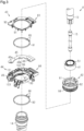
- the sensor device 4 includes a sensor magnet 41, a magnetic yoke assembly 42, a magnetic flux collecting unit 43, a gear unit 44, and a circuit board 45.
- the gear unit 44 includes two driven gears 46, 47 that rotate in response to rotation of the magnetic yoke assembly 42.
- the circuit board 45 includes: a magnetic sensor 48 that generates a signal according to the magnetic flux flowing through the magnetic flux collecting unit 43; and rotation sensors 49a, 49b that generate signals according to the rotation angles of the driven gears 46, 47.
- the signal output from the magnetic sensor 48 corresponds to the steering torque
- the signals output from the rotation sensors 49a, 49b correspond to the steering angle.
- the sensor device 4 may output the signal output from the magnetic sensor 48 itself and/or the signals output from the rotation sensors 49a, 49b themselves to the control device for the motor. Alternatively, the sensor device 4 may output, to the control device for the motor, the steering torque detected based on the signal output from the magnetic sensor 48 and/or the steering angle detected based on the signals output from the rotation sensors 49a, 49b.
- the sensor magnet 41 is a tubular ring magnet that has a circular shape as viewed in the axial direction.
- the sensor magnet 41 is magnetized in the radial direction such that magnetic poles of different polarities are arranged alternately in the circumferential direction.
- the sensor device 4 of the present embodiment includes a magnet holder 51, and the sensor magnet 41 is fixed to the outer peripheral surface of the input shaft 13 via the magnet holder 51.
- the sensor magnet 41 may be fixed directly to the outer circumferential surface of the input shaft 13.
- the sensor magnet 41 may be a plurality of plate-shaped magnets.
- Each of the yoke cores 61, 62 is made of a magnetic material and has an annular shape.
- the yoke cores 61, 62 are disposed spaced apart from each other in the axial direction.
- Each of the yoke cores 61, 62 has a ring portion 65, 66 and a plurality of claw portions 67, 68, respectively.
- the claw portions 67, 68 protrude in directions toward each other from their corresponding ring portions 65, 66.
- the claw portions 67, 68 are provided at equal intervals in the circumferential direction, and the claw portions 67 and the claw portions 68 are arranged alternately in the circumferential direction.
- annular as used in the present specification can refer to any shape that is generally annular, and includes an annular shape formed by combining a plurality of parts and an annular shape having a cut in its portion such as a C-shape.
- the "annular" shape includes, but is not limited to, shapes that are circular, elliptical, and polygonal with sharp or rounded corners as viewed in the axial direction.
- each of the yoke cores 61, 62 has a circular shape as viewed in the axial direction.
- the flange portion 72 is provided at the rear end of the body portion 71. In other words, the flange portion 72 is provided at the end of the body portion 71 that is located closer to the yoke cores 61, 62. Therefore, when assembling the sensor device 4, the collar 63 is fitted onto the output shaft 14 from the rear. In other words, the collar 63 is moved forward relative to the output shaft 14 to fit onto the output shaft 14. That is, the direction in which the collar 63 is fitted onto the output shaft 14 is a forward direction along the axis of the holder 64. The direction in which the collar 63 is fitted onto the output shaft 14 is also referred to as first direction.
- the holder 64 is made of, for example, a resin material and has a tubular shape. In the present embodiment, the holder 64 has a circular shape as viewed in the axial direction. The axial direction of the holder 64 coincides with the direction along the axis L.
- the holder 64 of the present embodiment is formed integral with the pair of yoke cores 61, 62 and the collar 63 by insert molding. In another embodiment, the holder 64 may be molded alone, and then the yoke cores 61, 62 and the collar 63 may be attached to the holder 64. The holder 64 holds the pair of yoke cores 61, 62 and the collar 63 on the axis L.
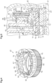
- the holder 64 includes: a yoke core holding portion 73 that holds the pair of yoke cores 61, 62; a collar holding portion 74 that holds the collar 63; a gear portion 75; and a positioning portion 76.
- the yoke core holding portion 73 holds the yoke cores 61, 62 such that inner surfaces of the claw portions 67, 68 are exposed on the inner peripheral side of the holder 64.
- the yoke core holding portion 73 also holds the yoke cores 61, 62 such that outer peripheral edges of the ring portions 65, 66 protrude radially outward from the holder 64.
- the gear portion 75 is provided next to the yoke core holding portion 73 in the axial direction of the holder 64.
- the gear portion 75 is continuous with the front of the yoke core holding portion 73.
- the gear portion 75 includes a plurality of external teeth 77 protruding radially outward from the holder 64, and tooth spaces 78 between the plurality of external teeth 77.
- the depth and thickness in an axial front end region of each external tooth 77 both decrease toward the front.
- the depth and thickness of each external tooth 77 may be constant in the axial direction.
- each tooth space 78 is open to the front in the axial direction, and a rear end of each tooth space 78 is closed by the ring portion 66 of the yoke core 62.
- the tooth spaces 78 are open in the direction in which the collar 63 is fitted onto the output shaft 14.
- the collar holding portion 74 holds the collar 63 such that an inner peripheral surface of the collar 63 is exposed on the inner peripheral side of the holder 64.
- the collar holding portion 74 of the present embodiment also holds the collar 63 such that the front end of the body portion 71 is exposed in the axial direction. In another embodiment, the front end of the body portion 71 may be covered by the collar holding portion 74.
- the collar holding portion 74 is provided at the inner periphery of the gear portion 75. That is, the collar 63 is provided at the inner periphery of the gear portion 75.
- the axial range in which the collar 63 is present in the holder 64 overlaps the axial range in which the gear portion 75 is provided in the holder 64. Specifically, the entire axial range in which the collar 63 is present in the holder 64 is included in the axial range in which the gear portion 75 is provided in the holder 64.
- the positioning portion 76 is provided so as to protrude axially rearward from the yoke core holding portion 73.
- the positioning portion 76 has, for example, a sector shape as viewed in the axial direction.
- the positioning portion 76 has, in its middle in the circumferential direction, a positioning groove 79 extending therethrough in the radial direction.
- the holder 64 includes two positioning portions 76.
- the present disclosure is not limited to this, and the holder 64 may have one positioning portion 76 or three or more positioning portions 76.
- the collar 63 is press-fitted on the rear end of the output shaft 14.
- the magnetic yoke assembly 42 is thus fixed to the output shaft 14 so as to be rotatable with the output shaft 14. With the magnetic yoke assembly 42 fixed to the output shaft 14, the magnetic yoke assembly 42 is disposed around the outer periphery of the sensor magnet 41 with a space therebetween. The end face of the rear end of the output shaft 14 abuts on the flange portion 72.
- the magnetic flux collecting unit 43 includes a pair of magnetic flux collecting members 81, 82, a first support frame 83, and a second support frame 84.
- Each of the magnetic flux collecting members 81, 82 is made of a magnetic material and has a C-shape.
- the magnetic flux collecting member 81 has two protrusions 85 that protrude in the radial direction, and the magnetic flux collecting member 82 has two protrusions 86 that protrude in the radial direction.
- the magnetic flux collecting member 81 is disposed around the outer periphery of the yoke core 61 with a space therebetween, and the magnetic flux collecting member 82 is disposed around the outer periphery of the yoke core 62 with a space therebetween. In other words, the magnetic flux collecting members 81, 82 are disposed spaced apart from each other in the axial direction.
- the magnetic flux flowing through the yoke core 61 is induced to the magnetic flux collecting member 81, and the magnetic flux flowing through the yoke core 62 is induced to the magnetic flux collecting member 82.
- the protrusions 85, 86 face each other in the axial direction.
- face refers to surfaces or members being positioned in front of each other, and includes not only when they are positioned completely in front of each other, but also when they are positioned partially in front of each other.
- face as used in the present specification includes both when a member that is different from two portions is interposed between the two portions, and when nothing is interposed between the two portions.
- the first support frame 83 includes an annular first frame portion 91 and a cover portion 92 provided radially outward of the first frame portion 91.
- the first frame portion 91 holds the magnetic flux collecting member 81 such that an inner peripheral surface of the magnetic flux collecting member 81 is exposed on the inner peripheral side of the first support frame 83.
- the second support frame 84 includes an annular second frame portion 93 and a support portion 94 provided radially outward of the second frame portion 93.
- the second frame portion 93 holds the magnetic flux collecting member 82 such that an inner peripheral surface of the magnetic flux collecting member 82 is exposed on the inner peripheral side of the second support frame 84.
- the support portion 94 supports the gear unit 44 and the circuit board 45.
- the cover portion 92 covers the circuit board 45 supported by the support portion 94 from the rear.
- the gear unit 44 includes sensor magnets 101, 102 that rotate with the driven gears 46, 47, and a support plate 103 in addition to the driven gears 46, 47.
- the sensor magnet 101 is fixed to the driven gear 46 so as to be rotatable with the driven gear 46.
- the sensor magnet 102 is fixed to the driven gear 47 so as to be rotatable with the driven gear 47.
- Peripheral configurations of the driven gear 47 are similar to those of the driven gear 46. Therefore, the meshing portion between the driven gear 46 and the gear portion 75 is shown in FIG. 5 , but the meshing portion between the driven gear 47 and the gear portion 75 is not shown in FIG. 5 .
- the support plate 103 has the shape of a flat plate.
- the support plate 103 rotatably supports the driven gears 46, 47.
- the support plate 103 is fixed to the second support frame 84 such that the driven gears 46, 47 are sandwiched between the support plate 103 and the support portion 94 of the second support frame 84.
- Each of the driven gears 46, 47 meshes with the gear portion 75 of the magnetic yoke assembly 42.
- the driven gears 46, 47 are disposed rearward of the rear end face of the output shaft 14. In other words, the driven gears 46, 47 are disposed in the direction opposite to the direction in which the collar 63 is fitted onto the output shaft 14, with respect to the rear end of the output shaft 14.
- the driven gears 46, 47 have different numbers of teeth. Therefore, when the output shaft 14, i.e., the gear portion 75, rotates, the rotation angle of the driven gear 46 and the rotation angle of the driven gear 47 are different from each other.
- the external teeth of the driven gears 46, 47 the depth and thickness in a rear end region of each external tooth in the present embodiment both decrease toward the rear. In another embodiment, the depth and thickness of each external tooth may be constant in the axial direction.
- the circuit board 45 has the shape of a flat plate. Various circuit elements including the magnetic sensor 48 and the rotation sensors 49a, 49b are mounted on the circuit board 45. The circuit board 45 is supported by the support portion 94 of the second support frame 84.
- the magnetic sensor 48 is, for example, a Hall sensor or a magnetoresistive sensor. As shown in FIG. 2 , the magnetic sensor 48 is mounted on a region of the circuit board 45 that is sandwiched between the protrusions 85, 86.
- the circuit board of another embodiment may include a redundant magnetic sensor different from the magnetic sensor 48, and this magnetic sensor may be mounted in a region of the circuit board 45 that is sandwiched between the other pair of protrusions 85, 86.
- the sensor magnet 41 rotates with the input shaft 13, and the magnetic yoke assembly 42 rotates with the output shaft 14.
- the relative positions of the sensor magnet 41 and the magnetic yoke assembly 42 in the circumferential direction change accordingly. Therefore, the magnetic flux flowing through the magnetic yoke assembly 42 changes according to the amount of twisting of the torsion bar 15, i.e., the magnitude of the steering torque input by the driver.
- the magnetic flux flowing through the magnetic flux collecting unit 43 also changes according to the change in magnetic flux flowing through the magnetic yoke assembly 42.
- the magnetic sensor 48 detects the magnetic flux flowing through the magnetic flux collecting unit 43, and generates a signal according to this magnetic flux, that is, a signal indicating the steering torque.
- the rotation sensors 49a, 49b are, for example, Hall sensors or magnetoresistive sensors. As shown in FIG. 5 , the rotation sensor 49a is mounted on a region of the circuit board 45 that faces the sensor magnet 101, and the rotation sensor 49b is mounted on a region of the circuit board 45 that faces the sensor magnet 102.
- the driven gears 46, 47 rotate in response to rotation of the magnetic yoke assembly 42.
- the rotation sensors 49a, 49b generate signals indicating the rotation angles of the driven gears 46, 47, i.e., the steering angle. Since the rotation angle of the driven gear 46 and the rotation angle of the driven gear 47 are different from each other as described above, the phases of the signals generated by the rotation sensors 49a, 49b are different from each other. Therefore, the sensor device 4 of the present embodiment can detect the steering angle as an absolute angle exceeding 360°, based on the signals output from the rotation sensors 49a, 49b.
- the sensor device 4 is assembled by attaching the components of the sensor device 4 to the output shaft 14 in order from the rear. Of these components, the magnetic yoke assembly 42 is attached after the gear unit 44 is fixed inside the housing 23.
- part of a jig is inserted into the positioning groove 79 to position the magnetic yoke assembly 42 with respect to the output shaft 14 in the circumferential direction.
- the magnetic yoke assembly 42 is attached to the output shaft 14 from the rear.
- the magnetic yoke assembly 42 is attached to the output shaft 14 and the magnetic yoke assembly 42 is meshed with the driven gears 46, 47.
- the sensor device 4 includes: the sensor magnet 41 that rotates with the input shaft 13; and the magnetic yoke assembly 42 that rotates with the output shaft 14.
- the sensor device 4 further includes: the pair of magnetic flux collecting members 81, 82 disposed around the outer periphery of the magnetic yoke assembly 42 with a space between the pair of magnetic flux collecting members 81, 82 and the outer periphery of the magnetic yoke assembly 42; and the magnetic sensor 48 that generates a signal according to the magnetic flux flowing through the pair of magnetic flux collecting members 81, 82.
- the sensor device 4 further includes: the driven gears 46, 47 that rotate in response to rotation of the magnetic yoke assembly 42; and the rotation sensors 49a, 49b that generate signals according to the rotation angles of the driven gears 46, 47.
- the magnetic yoke assembly 42 includes the pair of yoke cores 61, 62, the collar 63, and the holder 64 that holds the pair of yoke cores 61, 62 and the collar 63.
- the holder 64 includes the gear portion 75 having the plurality of external teeth 77 that protrude radially outward from the holder 64.
- the collar 63 is disposed at the inner periphery of the gear portion 75.
- the axial range in which the collar 63 is present in the holder 64 overlaps the axial range in which the gear portion 75 is provided in the holder 64. Therefore, the axial length of the holder 64 can be reduced and thus the size of the sensor device 4 can be reduced, as compared to the case where these axial ranges do not overlap each other.
- the steering column device 1 can thus be reduced in size while ensuring the EA stroke.
- the collar 63 includes the annular body portion 71 that is fitted on the output shaft 14, and the flange portion 72 that protrudes radially inward from the inner peripheral surface of the body portion 71 and that abuts on the end of the output shaft 14. Since the end of the output shaft 14 abuts on the flange portion 72, this facilitates axial positioning of the collar 63 with respect to the output shaft 14, i.e., axial positioning of the magnetic yoke assembly 42 with respect to the output shaft 14.
- the holder 64 further includes the positioning portion 76 for positioning the holder 64 with respect to the output shaft 14 in the circumferential direction. This facilitates circumferential positioning of the holder 64 with respect to the output shaft 14.
- the collar 63 is fitted to the rear end of the output shaft 14.
- the driven gears 46, 47 are disposed in the direction opposite to the first direction with respect to the rear end of the output shaft 14. Therefore, when attaching the magnetic yoke assembly 42, the collar 63 begins to fit onto the outer periphery of the output shaft 14 after at least part of the gear portion 75 meshes with the driven gears 46, 47. It is thus possible to fit the collar 63 onto the output shaft 14 after meshing the gear portion 75 with the driven gears 46, 47 in a state where the circumferential position of the magnetic yoke assembly 42 can be easily changed.
- the present embodiment can be modified as follows.
- the present embodiment and the following modifications can be combined as long as no technical contradiction arises.
Landscapes
- Physics & Mathematics (AREA)
- General Physics & Mathematics (AREA)
- Engineering & Computer Science (AREA)
- Electromagnetism (AREA)
- Chemical & Material Sciences (AREA)
- Combustion & Propulsion (AREA)
- Transportation (AREA)
- Mechanical Engineering (AREA)
- Power Steering Mechanism (AREA)
- Power Engineering (AREA)
Applications Claiming Priority (1)
| Application Number | Priority Date | Filing Date | Title |
|---|---|---|---|
| PCT/JP2022/011021 WO2023170956A1 (ja) | 2022-03-11 | 2022-03-11 | 磁気ヨークアセンブリ及びセンサ装置 |
Publications (2)
| Publication Number | Publication Date |
|---|---|
| EP4492012A1 true EP4492012A1 (de) | 2025-01-15 |
| EP4492012A4 EP4492012A4 (de) | 2025-04-16 |
Family
ID=87936396
Family Applications (1)
| Application Number | Title | Priority Date | Filing Date |
|---|---|---|---|
| EP22930937.2A Pending EP4492012A4 (de) | 2022-03-11 | 2022-03-11 | Magnetische jochanordnung und sensorvorrichtung |
Country Status (5)
| Country | Link |
|---|---|
| US (1) | US20250137816A1 (de) |
| EP (1) | EP4492012A4 (de) |
| JP (1) | JP7689242B2 (de) |
| CN (1) | CN118843779A (de) |
| WO (1) | WO2023170956A1 (de) |
Family Cites Families (7)
| Publication number | Priority date | Publication date | Assignee | Title |
|---|---|---|---|---|
| WO2005068962A1 (de) * | 2004-01-20 | 2005-07-28 | Valeo Schalter Und Sensoren Gmbh | Vorrichtung zum bestimmen eines lenkwinkels und eines an einer lenkwelle ausgeübten drehmoments |
| JP2014065367A (ja) * | 2012-09-25 | 2014-04-17 | Panasonic Corp | 回転角度・トルク検出装置 |
| DE102012024383A1 (de) * | 2012-12-13 | 2014-06-18 | Valeo Schalter Und Sensoren Gmbh | Vorrichtung mit einer Drehmomentsensoreinrichtung und einer Lenkwinkelsensoreinrichtung für ein Kraftfahrzeug, Kraftfahrzeug und Verfahren zum Herstellen einer Vorrichtung |
| KR102068187B1 (ko) * | 2013-08-09 | 2020-01-20 | 엘지이노텍 주식회사 | 토크앵글센서 |
| EP3660479B1 (de) * | 2017-07-24 | 2025-11-26 | LG Innotek Co., Ltd. | Drehmomentsensor |
| JP7099263B2 (ja) | 2018-11-08 | 2022-07-12 | 株式会社ジェイテクト | ヨーク組立体、及びトルク検出装置、並びにヨーク組立体の製造方法 |
| JP7268510B2 (ja) | 2019-07-09 | 2023-05-08 | 株式会社ジェイテクト | センサ装置 |
-
2022
- 2022-03-11 EP EP22930937.2A patent/EP4492012A4/de active Pending
- 2022-03-11 WO PCT/JP2022/011021 patent/WO2023170956A1/ja not_active Ceased
- 2022-03-11 CN CN202280093223.XA patent/CN118843779A/zh active Pending
- 2022-03-11 US US18/836,631 patent/US20250137816A1/en active Pending
- 2022-03-11 JP JP2024505837A patent/JP7689242B2/ja active Active
Also Published As
| Publication number | Publication date |
|---|---|
| JPWO2023170956A1 (de) | 2023-09-14 |
| WO2023170956A1 (ja) | 2023-09-14 |
| CN118843779A (zh) | 2024-10-25 |
| US20250137816A1 (en) | 2025-05-01 |
| JP7689242B2 (ja) | 2025-06-05 |
| EP4492012A4 (de) | 2025-04-16 |
Similar Documents
| Publication | Publication Date | Title |
|---|---|---|
| EP1535825B1 (de) | Elektrische Servolenkung und Herstellungsverfahren dafür | |
| JP4955737B2 (ja) | 操舵制御装置 | |
| JP5978079B2 (ja) | トルクセンサ | |
| JP2904329B2 (ja) | ステアリング装置 | |
| EP3715221B1 (de) | Sensorvorrichtung | |
| WO2013146425A1 (ja) | 電動パワーステアリング装置 | |
| JP2016013821A (ja) | 電動パワーステアリング装置 | |
| JP2007269281A (ja) | ステアリング装置 | |
| JP2008017549A (ja) | 車両用操舵装置 | |
| US8066094B2 (en) | Electric power steering device | |
| JP2023132532A (ja) | 電動パワーステアリング装置 | |
| US20250137816A1 (en) | Magnetic yoke assembly and sensor device | |
| JP2002116098A (ja) | トルクセンサ | |
| EP3680636B1 (de) | Drehmomentsensor und drehwinkelsensor integriert | |
| JP2008298531A (ja) | 角度センサおよび電動パワーステアリング装置 | |
| WO2024150834A1 (ja) | トルクセンサ | |
| JP2018128387A (ja) | 電動パワーステアリング装置、及び車両 | |
| JP5945743B2 (ja) | 電動パワーステアリング装置用モータ及びこれを用いた電動パワーステアリング装置 | |
| JP4235894B2 (ja) | 電動パワーステアリング装置 | |
| WO2025186868A1 (ja) | 操舵装置 | |
| JP6390904B2 (ja) | ステアリング装置 | |
| KR102178637B1 (ko) | 토크앵글센서 | |
| JP2022070693A (ja) | トルクセンサ | |
| WO2026058750A1 (ja) | トルクセンサ | |
| JP2024041101A (ja) | 操舵装置 |
Legal Events
| Date | Code | Title | Description |
|---|---|---|---|
| STAA | Information on the status of an ep patent application or granted ep patent |
Free format text: STATUS: THE INTERNATIONAL PUBLICATION HAS BEEN MADE |
|
| PUAI | Public reference made under article 153(3) epc to a published international application that has entered the european phase |
Free format text: ORIGINAL CODE: 0009012 |
|
| STAA | Information on the status of an ep patent application or granted ep patent |
Free format text: STATUS: REQUEST FOR EXAMINATION WAS MADE |
|
| 17P | Request for examination filed |
Effective date: 20240829 |
|
| AK | Designated contracting states |
Kind code of ref document: A1 Designated state(s): AL AT BE BG CH CY CZ DE DK EE ES FI FR GB GR HR HU IE IS IT LI LT LU LV MC MK MT NL NO PL PT RO RS SE SI SK SM TR |
|
| A4 | Supplementary search report drawn up and despatched |
Effective date: 20250314 |
|
| RIC1 | Information provided on ipc code assigned before grant |
Ipc: G01L 5/22 20060101ALI20250311BHEP Ipc: G01L 3/10 20060101ALI20250311BHEP Ipc: G01D 5/14 20060101ALI20250311BHEP Ipc: B62D 15/02 20060101ALI20250311BHEP Ipc: B62D 6/10 20060101ALI20250311BHEP Ipc: G01D 5/245 20060101AFI20250311BHEP |
|
| RAP1 | Party data changed (applicant data changed or rights of an application transferred) |
Owner name: JTEKT CORPORATION |
|
| DAV | Request for validation of the european patent (deleted) | ||
| DAX | Request for extension of the european patent (deleted) |