EP4491937A2 - Netzwerkkantendetektion und meldung einer gasdrucksituation - Google Patents
Netzwerkkantendetektion und meldung einer gasdrucksituation Download PDFInfo
- Publication number
- EP4491937A2 EP4491937A2 EP24217214.6A EP24217214A EP4491937A2 EP 4491937 A2 EP4491937 A2 EP 4491937A2 EP 24217214 A EP24217214 A EP 24217214A EP 4491937 A2 EP4491937 A2 EP 4491937A2
- Authority
- EP
- European Patent Office
- Prior art keywords
- gas
- pressure
- devices
- over
- gas pressure
- Prior art date
- Legal status (The legal status is an assumption and is not a legal conclusion. Google has not performed a legal analysis and makes no representation as to the accuracy of the status listed.)
- Pending
Links
Images




Classifications
-
- F—MECHANICAL ENGINEERING; LIGHTING; HEATING; WEAPONS; BLASTING
- F17—STORING OR DISTRIBUTING GASES OR LIQUIDS
- F17D—PIPE-LINE SYSTEMS; PIPE-LINES
- F17D1/00—Pipe-line systems
- F17D1/02—Pipe-line systems for gases or vapours
- F17D1/04—Pipe-line systems for gases or vapours for distribution of gas
-
- G—PHYSICS
- G08—SIGNALLING
- G08B—SIGNALLING SYSTEMS, e.g. PERSONAL CALLING SYSTEMS; ORDER TELEGRAPHS; ALARM SYSTEMS
- G08B21/00—Alarms responsive to a single specified undesired or abnormal condition and not otherwise provided for
- G08B21/02—Alarms for ensuring the safety of persons
- G08B21/12—Alarms for ensuring the safety of persons responsive to undesired emission of substances, e.g. pollution alarms
- G08B21/16—Combustible gas alarms
-
- G—PHYSICS
- G01—MEASURING; TESTING
- G01M—TESTING STATIC OR DYNAMIC BALANCE OF MACHINES OR STRUCTURES; TESTING OF STRUCTURES OR APPARATUS, NOT OTHERWISE PROVIDED FOR
- G01M3/00—Investigating fluid-tightness of structures
- G01M3/02—Investigating fluid-tightness of structures by using fluid or vacuum
- G01M3/04—Investigating fluid-tightness of structures by using fluid or vacuum by detecting the presence of fluid at the leakage point
- G01M3/20—Investigating fluid-tightness of structures by using fluid or vacuum by detecting the presence of fluid at the leakage point using special tracer materials, e.g. dye, fluorescent material, radioactive material
- G01M3/22—Investigating fluid-tightness of structures by using fluid or vacuum by detecting the presence of fluid at the leakage point using special tracer materials, e.g. dye, fluorescent material, radioactive material for pipes, cables or tubes; for pipe joints or seals; for valves; for welds; for containers, e.g. radiators
- G01M3/224—Investigating fluid-tightness of structures by using fluid or vacuum by detecting the presence of fluid at the leakage point using special tracer materials, e.g. dye, fluorescent material, radioactive material for pipes, cables or tubes; for pipe joints or seals; for valves; for welds; for containers, e.g. radiators for valves
-
- G—PHYSICS
- G08—SIGNALLING
- G08B—SIGNALLING SYSTEMS, e.g. PERSONAL CALLING SYSTEMS; ORDER TELEGRAPHS; ALARM SYSTEMS
- G08B27/00—Alarm systems in which the alarm condition is signalled from a central station to a plurality of substations
- G08B27/005—Alarm systems in which the alarm condition is signalled from a central station to a plurality of substations with transmission via computer network
-
- G—PHYSICS
- G08—SIGNALLING
- G08B—SIGNALLING SYSTEMS, e.g. PERSONAL CALLING SYSTEMS; ORDER TELEGRAPHS; ALARM SYSTEMS
- G08B27/00—Alarm systems in which the alarm condition is signalled from a central station to a plurality of substations
- G08B27/006—Alarm systems in which the alarm condition is signalled from a central station to a plurality of substations with transmission via telephone network
-
- F—MECHANICAL ENGINEERING; LIGHTING; HEATING; WEAPONS; BLASTING
- F17—STORING OR DISTRIBUTING GASES OR LIQUIDS
- F17C—VESSELS FOR CONTAINING OR STORING COMPRESSED, LIQUEFIED OR SOLIDIFIED GASES; FIXED-CAPACITY GAS-HOLDERS; FILLING VESSELS WITH, OR DISCHARGING FROM VESSELS, COMPRESSED, LIQUEFIED, OR SOLIDIFIED GASES
- F17C2265/00—Effects achieved by gas storage or gas handling
- F17C2265/06—Fluid distribution
- F17C2265/068—Distribution pipeline networks
Definitions
- gas pressure within a portion of a gas distribution system gets too high, it can cause pipes to burst, the venting of gas, dangerous pilot lights, damage to appliances and/or buildings, and even fires and explosions.
- Monitoring gas pressure is a complex matter, in part because pressure can vary due to many factors, including gas supply, user gas demand, pipe lengths, bends, joints, and gas friction with pipe interiors and other gas.
- known systems tend to respond slowly to over-pressure events, in part because of latencies within communication networks, headend application latencies, and human delays. Accordingly, substantial gas pressure increases can result in damage before the increases are detected, reversed and/or mitigated.
- a first device measures gas pressure. If a gas pressure that is over a threshold value is detected, the first device sends a message to a second device, which may be near the first device (e.g., both devices may be on a same gas delivery pipeline). The second device may respond by indicating its own gas over-pressure condition, thereby suggesting that the gas over-pressure condition is not localized at the first device (e.g., a first smart gas meter). Alternatively, the second device may not detect and/or report an over-pressure condition, thereby suggesting that the over-pressure condition may be localized to the first device.
- the first device may share information about its over-pressure condition with devices within a group defined to include the first and the second devices and other devices.
- Members of the group may share information with devices in any group(s) in which they are members and/or with devices that are within a threshold physical (geographic) distance.
- An appropriate response may be made within the gas delivery system depending on if the over-pressure condition is localized to the first device, or more widely present within the group of devices.
- protective measures may be taken, such as closing valves providing gas to appropriate service sites, and such as sending warning notices to a headend device (e.g., to the utility company), to users' devices including users' cellphones and in-home devices, and to any other device(s) that may assist in mitigating damage and/or injury.
- a headend device e.g., to the utility company
- users' devices including users' cellphones and in-home devices, and to any other device(s) that may assist in mitigating damage and/or injury.
- FIG. 1 shows an example gas delivery system 100. If pressure in an area of the gas distribution system 100 is too high, the pressure may cause damage.
- the gas delivery system 100 is configured having devices and techniques of operation that detect, notify and mitigate or resolve overly high gas pressure conditions.
- a major gas main 102 supplies gas to several local gas mains 104, 106.
- the local gas main 104 supplies gas to large gas volume customer(s) 108 having associated gas pressure regulators and metering devices 110.
- the local gas main 106 supplies gas to commercial customer(s) 112 having associated gas pressure regulators and metering devices 114.
- the local gas main 106 also supplies gas to residential customer(s) 116, 118 having associated gas pressure regulators and metering devices 120, 122.
- the local gas main 104 and the devices attached to it may constitute a group of devices for purposes of an algorithm (discussed at FIGS. 5-9 and other locations) that detects, notifies and/or mitigates/resolves a situation wherein devices within the logical group detect gas pressure over a threshold value.
- the group may be based at least in part on knowledge of the topology of the gas delivery system.
- a topological description of the gas delivery system may be configured within a database or other data structure. In an example, the topological description may include a listing of devices in the system, their characteristics, and how, when, where, and/or to what they are connected.
- the topology may include "states" of devices, such as a valve being open or closed, or a gas main having a certain pressure, a battery having a certain charge, etc.
- the local gas main 106 and devices attached to it may constitute a second group.
- Each device in the system 100 may be considered to be in one or more groups.
- the groups may be formed in a manner that logically groups devices so that data from one device may be synergistically interpreted using data from other device(s) in the group. For example, if one device recognizes a gas pressure over a threshold pressure value, that event is reported to other devices in a group. A confirmation of high pressure by other devices in the group tends to indicate a region of high gas pressure rather than an area of localized high gas pressure.
- a liquid natural gas (LNG) plant 124 provides gas to the delivery system 100 at local gas main 126.
- Compressor stations 128 create, regulate and/or maintain the gas pressure within gas mains and local delivery pipes within the system 100.
- An underground gas storage reservoir 130 and regulator 132 provide additional gas through a gas pipe 134 to the system 100.
- locations having higher gas pressures upstream e.g., the LNG plant 124, the compressor stations 128, and the underground storage 130
- areas having lower pressures downstream e.g., the customers 108, 112, 116 and 118.
- gas pressure within the gas delivery system 100 can vary from city gate regulators/meters 136 in the system to the downstream service point gas pressure regulators and meters.
- Example factors resulting in pressure drop include pipe length, pipe bends and joints, and internal gas-against-gas and gas-against-pipe friction.
- the example system 100 is configured to monitor pressure at a plurality of points, thereby providing control systems and techniques of operation that anticipate, detect and/or mitigate unsafe situations, and avoid unsafe situations resulting from network latencies, headend application latencies, and/or human delays.
- the gas meter/gas pressure regulator 114 is configured to include edge detection and gas pressure notification systems and techniques 138.
- the techniques 138 are enabled by execution of software, which may be defined in memory and executed by a processor.
- Other devices shown in the system 100 may contain the same or similar edge detection and gas pressure notification systems and techniques 138.
- the edge detection and gas pressure notification systems and techniques 138 are configured and operate according to one or more of the examples shown, discussed and/or suggested by the examples of FIGS. 2-9 .
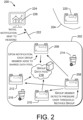
- FIG. 2 shows an example gas delivery system 200 illustrating example functionality of groups of devices, particularly showing a data-gathering functionality.
- a first example group 202 of devices includes four gas meters 206-212.
- the first group 202 additionally includes two valves 214, 216.
- the valves may be associated with segment pipelines or "stub pipelines" off a main gas pipeline (e.g., pipes 104, 106 of FIG. 1 ).
- the valves 214, 216 may allow gas to be turned on/off to more than one gas service site (i.e., more than one gas metering device).
- the first group 202 may also include a group data pool 218, which may be located in any desired location, such as a remote server, one or more of the gas metering devices, or a dedicated device, etc.
- the data pool 218 may include information regarding a topology of some or all of the gas delivery system 200, and time-stamped pressure measurements and/or pressure thresholds of gas pressure measuring devices in one or more groups of devices.
- the data pool 218 may also identify groups of devices according to geography and/or connectivity within the gas delivery system topology.
- a group may include devices on a segment of gas pipeline serving a related group of gas customers (e.g., related by use of a same gas main and/or related by physical distance between any two devices of less than a threshold value).
- the example gas delivery system 200 may also include other group(s), represented for drawing simplicity by group 204 and gas meter 220.
- group 204 and gas meter 220 The number of groups and the number of devices in each group may be based on the needs, conditions and design specification of a particular system, and are shown in FIG. 2 only to illustrate general concepts and not as requirements.
- devices with pressure sensors can periodically compare their pressure readings to one or more high gas-pressure threshold values.
- the comparison may be made at prescribed intervals, random times, etc., as indicated by system design requirements, including available battery power, time since detection of an over-pressure event, and/or other considerations. If a device (e.g., a smart gas meter) detects that pressure has passed a relevant threshold value, the device can increase the rate of its gas-pressure sampling. Conversely, if the device detects normal gas pressure values for over a relevant threshold time value, it can decrease the rate of its gas-pressure sampling.
- the device can send its latest pressure reading(s)-and in some examples, its relevant threshold values(s)-to its neighboring devices (e.g., devices within the group of devices) that also have gas pressure sensors.
- its neighboring devices e.g., devices within the group of devices
- a group member e.g., smart gas metering device 208
- other pressure sensing devices in the group e.g., smart gas metering devices 206, 210, 212
- the other pressure sensing devices can add their own data set to the data pool 218 (e.g., a data pool associated with sensing devices in a geographic area and/or devices within a logical group).
- the data pool 218 may be used to determine if an over-pressure event is area-wide (e.g., caused by events on the distribution side) or if it is localized to the single service point and/or device.
- Such a collaboration between devices distributed on (or near) the edge of a gas distribution system reduces the chance that decisions will be made based on false positives.
- Data from group 202 may be sent (e.g., by cellular or internet connection 222) to a headend device.
- the data sent to the headend device 224 may include an initial notification by one of the gas pressure-measuring devices that a high gas pressure event (e.g., gas pressure over a threshold) has been detected.
- the measured gas pressure and the threshold may be sent to the headend device.
- the threshold is relevant at least in that it puts into perspective what the preferred gas pressure is at the location at which the measurement was made.
- the headend device 224 may be a server of a utility company, a third-party contractor of the utility company, or may be another device.
- the data 226 received from gas pressure-measuring devices and/or groups of such devices may be displayed for the situational-awareness of human operator(s) and/or used in algorithms that are involved in data-gathering, data-processing, and response(s) to gas over-pressure events.
- Example responses may include damage prevention procedures, such as shutting valves to prevent increases in gas pressure.
- FIG. 3 shows an example gas delivery system 300 containing enhancements to the gas delivery system 200 seen in FIG. 2 .
- the gas delivery system 300 performs data-processing functions that formulate response(s) to gas over-pressure events, and send appropriate commands to initiate the response(s).
- the responses may address local gas over-pressure events (e.g., detected by a single smart gas metering device) or area-wide gas over-pressure events (e.g., detected by plural smart gas metering devices within a group of devices).
- an algorithm 302 may utilize data from the group data pool 218 of FIG. 2 to determine a response to an over-pressure event seen by: a gas pressure-measuring device from among those in a group; and/or a group of smart gas pressure-measuring devices.
- the algorithm 302 may be based at least in part on the techniques and methods presented in FIGS. 5 through 9 .
- the group is typically based on a topology of the gas delivery system, and may include pipelines, smart gas meters (e.g., meters with gas pressure-measuring capabilities), other gas pressure gauges, valves, and other devices.
- the group algorithm 302 can consider the rate of pressure increase so that severity and urgency of the issue can be evaluated. If the rate of gas pressure increase is "slower" (e.g., a rate of change that is less than a threshold value), then the devices may provide instructions for an initial mitigating action that includes a service technician dispatched by the utility company.
- the group of devices determines that the situation is "faster” (e.g., a rate of change that is greater than the threshold value), then immediate mitigating action should be taken.
- the algorithm may direct the group of devices to perform automatic shutoffs of their own valves, send shutoff commands to valves in other devices around them, send alarms with pressure sampling data to the headend system for utility notification, and send alerting information to customers' cellular phones 304 and/or in-home devices 306 to warn the end-customer of the safety situation.
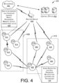
- FIG. 4 shows an example gas delivery system 400 illustrating data collection, data transmission, and data utilization.
- a central office 402 may be operated by a utility company, a third-party contractor or other entity.
- the central office may be in communications with networks 404, such as the internet and/or cellular telephone networks, or proprietary networks.
- a router device 406 may (optionally) be in communication with a plurality of devices in one or more groups 408, 410 of devices of the gas delivery system 400.
- the first group of devices includes smart gas metering devices 412-418 and the second group of devices 420-426.
- Each smart gas metering device may include hardware devices 428.
- the hardware devices 428 may include one or more of a gas metering device, a gas pressure sensor, a radio, a processor, a memory device, and/or a gas valve, etc.
- the devices 428 may be configured (e.g., with software) to perform some or all of the edge detection and gas pressure recognition, notification, and mitigation/repair systems and techniques 138.
- the methods of operation may be performed by one or more application specific integrated circuits (ASIC) or may be performed by a general-purpose processor utilizing software defined in computer readable media.
- the memory e.g., the memory device(s) of hardware 428) may comprise computer-readable media and may take the form of volatile memory, such as random-access memory (RAM) and/or non-volatile memory, such as read only memory (ROM) or flash RAM.
- RAM random-access memory
- ROM read only memory
- Computer-readable media devices include volatile and non-volatile, removable and non-removable media implemented in any method or technology for storage of information such as computer-readable instructions, data structures, program modules, or other data for execution by one or more processors of a computing device.
- Examples of computer-readable media include, but are not limited to, phase change memory (PRAM), static random-access memory (SRAM), dynamic random-access memory (DRAM), other types of random access memory (RAM), read-only memory (ROM), electrically erasable programmable read-only memory (EEPROM), flash memory or other memory technology, compact disk read-only memory (CD-ROM), digital versatile disks (DVD) or other optical storage, magnetic cassettes, magnetic tape, magnetic disk storage or other magnetic storage devices, or any other non-transitory medium that can be used to store information for access by a computing device.
- PRAM phase change memory
- SRAM static random-access memory
- DRAM dynamic random-access memory
- RAM random access memory
- ROM read-only memory
- EEPROM electrically erasable programmable read-only memory
- flash memory or other memory technology
- CD-ROM compact disk read-only memory
- DVD digital versatile disks
- computer-readable media does not include transitory media, such as modulated data signals and carrier waves, and/or signals.
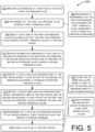
- FIG. 5 shows an example method 500 of detecting a high gas pressure condition.
- the method detects high gas pressure situation(s) within a gas delivery system.
- a first device e.g., smart gas metering device
- the message is sent to device(s) within a group of devices based on gas system topography (e.g., the group of devices are smart metering devices having a common gas supply line).
- the receiving devices may respond by indicating if they are experiencing a gas over-pressure condition. If so, the gas over-pressure condition is not localized at the first device.
- the second device(s) may indicate that it/they is/are not in an over-pressure condition, thereby suggesting that the over-pressure condition may be localized to the first device.
- An appropriate response may be made within the gas delivery system depending on if the over-pressure condition is localized to the first device, or more widely present within the group of devices.
- protective measures may be taken, such as closing valves providing gas to appropriate service sites.
- gas pressure is measured at a device to obtain a first gas pressure value.
- the first device may be the smart metering device 206, and may measure gas pressure at a customer's site.
- the smart metering device 206 may perform the calculation with respect to the first threshold value. In other examples, the calculation may be performed at a headend device or other location. In the example of block 506, in response to determining that the first gas pressure value exceeds the first threshold value, a rate at which gas pressure is measured is increased.
- At block 508 at least one of the first gas pressure value, a threshold value, and an indication that the first gas pressure value exceeds the first threshold value is sent from the first device to second device(s).
- the second device(s) to which data is sent are selected from among devices in a group also including the first device.
- the gas pressure information of one or more group members can be used synergistically to anticipate gas over-pressure events at other group members.
- the data is sent from the first device to devices selected based on a topology of the gas delivery system (e.g., the device(s) may be selected based on connection to a same gas main), possibly without formally defining groups of devices.
- the data is sent from the first device to device(s) less than a threshold distance from the first device.
- the data is sent from the first device to device(s) based on one or more of the above examples.
- information comprising at least one of a second gas pressure value indicating gas pressure at the second device or an indication of whether the second gas pressure value exceeds a second threshold value is received.
- the first device receives the information.
- the information could be received at a headend server or other device at any location.
- "local" high gas-pressure event may be reported, if high gas pressure was detected only at the first device.
- a high gas-pressure event at the device may be based at least in part on the second gas pressure value being at or below the second threshold value. In the example, if the second gas pressure of the second device does not exceed that device's threshold value then only a local high gas-pressure event at the first device is reported.
- a "group-wide" high gas-pressure event may be reported, if high gas pressure was detected at the first device and at the second device(s).
- a high gas-pressure event within a distribution area of the device and the second device is reported (e.g., to a headend device and/or to all devices within the group) based at least in part on the second gas pressure value (at the second device) exceeding the second threshold value (which may or may not be the same as the first threshold value).
- a high gas-pressure event may be anticipated because the rate of gas pressure increase is high at any device, even if the gas pressure has not yet exceeded a threshold value.
- a rate of gas pressure increase e.g., at the first device or second device
- a third threshold value e.g., if the actual gas pressure has not yet exceeded a threshold value
- a first gas valve of the first device is closed based at least in part on the high gas-pressure event at the first device.
- the first gas valve may be closed in response to a local high gas-pressure event.
- gas valves at additional devices may be closed based on gas pressure exceeding respective thresholds of the additional devices.
- the second gas valve of the second device (e.g., the device discussed at block 510) may be closed in response to a high gas-pressure event at that device.
- devices within a group of devices are notified and/or directed to close their respective gas valves. In an example, this direction may be in response to high gas-pressure events at the first and second devices. Because the group of devices is based at least in part on the topology of the gas delivery system, all devices in the group may be under a high gas-pressure condition, and closing some or all of the gas valves within the group may be indicated.
- FIG. 6 shows example techniques 600 for selecting a second device to which to send a message.
- information was sent from the first device (which recognized a gas over-pressure event at its location) to one or more other devices.
- the device sensing an over-pressure event attempts to determine if the over gas-pressure condition is limited in extent (e.g., limited to itself), or more broadly includes other devices.
- the techniques 600 include two examples, which may be used singly or in combination, to determine to which device(s) a first device that senses an over-pressure event should send over-pressure information and send a request (explicit or implied) for the receiving device to perform tasks, such as measuring gas pressure, increasing a frequency or rate of such measurements, comparing measurements to thresholds, and/or taking actions to lessen/prevent damage from a high gas pressure event.
- a first device if the first device sends its gas pressure information to one or more other devices, those device(s) may assume that the first device is experiencing an over-pressure event (i.e., the over-pressure event at the first device is why the message was sent).
- the second device(s) may readily determine the amount by which measured gas pressure at the first device exceeded a threshold of the first device.
- second device(s)-to which the first device may send gas pressure and/or threshold value information- may be selected from among a plurality of devices.
- the selecting is based at least in part on data describing aspects of a topology of a gas delivery system to which the first device and the second device are connected, and wherein the selecting is performed prior to the sending.
- the selecting is based at least in part on a distance between the first and second devices. If the distance between the first device and other devices is less than a threshold distance, the first device may send gas pressure and/or threshold value information to those devices.
- an RF signal strength of a signal sent by the second device is measured.
- the signal strength of the second device, measured at the first device helps the first device determine a distance to the second device.
- the second device may be selected from among a plurality of devices based at least in part on the measured RF signal strength of each respective device from among the plurality of devices. In an example, a device is selected based on which device(s) appear to be closer to the first device, or which device(s) are less than a threshold distance from the first device.
- FIG. 7 shows example techniques 700 for responding to a high gas pressure condition.
- the techniques 700 include two examples, which may be used singly or in combination, to mitigate or prevent damage to the gas supply system and/or customers' appliances and infrastructure that might otherwise result in an over-pressure event.
- a valve is closed on a single device to prevent additional gas from entering a part of the gas delivery system, which would further increase the gas pressure.
- valves are closed on multiple devices to prevent such damage.
- a shutdown command is sent to a group of devices.
- each device in the group of devices is connected to a gas main to which the device is connected or is within a threshold distance of the device.
- the region includes the device and the second device.
- the region includes all devices (e.g., smart gas meters) attached to a same gas delivery pipe.
- the region includes all devices within a group of devices, and the group is defined based at least on a database containing a topological description of the gas delivery system.
- the topological description of the gas delivery system may include a listing of devices in the system, their characteristics, and how, when, where, and/or to what they are connected.
- FIG. 8 shows additional example techniques 800 for responding to a high gas pressure condition.
- the techniques 800 include three examples 802-806, which may be used singly or in one or more combinations, to send messages to devices (e.g., cellular devices, in-home devices, headend devices, etc.).
- the messages may be sent in response to a first device detecting over-pressure gas conditions or a second device that checked gas pressure conditions responsive to message(s) from the first device.
- a message may be sent to a first cellular phone or to a first in-home device associated with the first device (e.g., a smart gas meter).
- the message may warn the recipient of an over-pressure event, and may suggest a course of action (such as evacuation of the property).
- the message may be sent to authorities (e.g., 911, emergency, the fire department, etc.).
- authorities e.g., 911, emergency, the fire department, etc.
- the message may include the nature of the over-pressure event, the address(es) of the event, a suggested course of action, etc.
- the message (or a similar message) may be sent to a second cellular telephone or to a second in-home device associated with a service site within a threshold distance of the first device.
- Messages e.g., warnings
- the message (or a similar message) may be sent to a headend device, based at least in part on at least one condition being true, the conditions including: the first gas pressure value exceeds the first threshold value; and the second gas pressure value exceeds the second threshold value.
- FIG. 9 shows example techniques 900 for defining and using groups of devices, detection of a gas over-pressure condition, and reporting the over-pressure event affecting the group of devices.
- the techniques 900 include grouping devices based at least in part on gas system topography, determining that gas-pressure threshold(s) have been exceeded at one or more devices in a group of devices, and reporting gas over-pressure events in messages and/or warnings to users and/or authorities (e.g., 911).
- the reporting may be based at least in part on the group associated with the device(s) found to have over-pressure events.
- the reporting can include devices that are in danger of an over-pressure event but may not have even realized the situation. The failure to realize the situation may result from a frequency of gas pressure measurement. Accordingly, the use of groups leverages the measurements of one device (e.g., smart gas meter) to protect the service site of another device.
- a group of devices is defined based at least in part on a topology of a gas delivery system.
- the topology may be used to organize the group based on some or all devices related to, or attached to, a gas pipeline serving a number of customer sites.
- each device of the group may be within a threshold distance of all other devices of the group.
- the devices may include a gas source (e.g., an LNG plant), a pipeline, a number of smart gas meters, gas valves, in-home devices, etc.
- gas pressure measurements exceed respective thresholds at one or more devices within the group of devices.
- the number of devices with gas pressure that is over-pressure may be compared to a third threshold, such as to reduce false positives.
- one device measures gas pressure over a threshold and alerts other device(s) to measure their gas pressure and/or increase a frequency of gas pressure measurements.
- an over-pressure event that affects the group of devices is reported.
- the over-pressure event may be reported by one or more smart gas meters or other devices.
- the over-pressure event may be reported to the customer(s) at affected sites, including reports made to in-home devices, cellular telephones, etc. Reports may be sent to customer(s) at sites that are geographically near the affected sites. Alternatively, or additionally, reports may be sent to customer(s) at sites that are related to site(s) detecting the over-pressure event by aspects of the topology of the gas delivery system.
- the aspects of the topology may include sites served by a same gas main, sites served by a same gas supply facility, sites having gas flow affected by same valve(s), etc.
- gas pressure in an area of a gas distribution system gets too high, it can cause pipe bursting, gas venting, enlarged and unsafe pilot lights, and possibly fires and explosions. Gas flows from higher pressures upstream to lower pressures downstream. Additionally, the gas pressure within a gas delivery system can vary from city gate regulators and meters in the system to the end service point regulators and meters. Example factors governing pressure drop include the length of runs (e.g., the length of gas mains), number of pipe bends and joints, and internal gas against pipe friction. By monitoring pressure at a plurality of points, the system increases the ability for utility companies to anticipate, detect and/or mitigate unsafe situations, and avoid unsafe situations with network latencies, headend application latencies, and human delays.
- the systems and techniques e.g., smarter gas metering devices
- the systems and techniques also monitor not only at the single point at which the equipment is installed, but also an area surrounding the location of the equipment. In the example, such monitoring is performed by exchanging information with smart metering devices at nearby service sites.
- the gas delivery system performs actions that automatically mitigate unsafe situation(s).
- Devices with pressure sensors can periodically compare their pressure readings to one or more high gas-pressure threshold values. If a device detects that pressure has passed one of the thresholds it can increase the rate of its pressure sampling and can send its latest pressure readings and thresholds to its neighboring devices that also have pressure sensors.
- the other pressure sensing devices can likewise increase their rate of pressure sampling and add their own data set to a group data pool (e.g., a data pool associated with sensing devices in a logical group defined according to a geographic area, according to pipelines, and/or according to a gas supply topology).
- the data pool may be used to determine if an over-pressure event is area-wide (e.g., caused by events on the distribution side) or if it is localized to the single service point and/or device. Such a collaboration between devices distributed on (or near) the edge of a gas distribution system reduces the chance that decisions will be made based on false positives.
- the group algorithm can consider the rate of pressure increase so that severity and urgency of the issue can be evaluated. If the rate of gas pressure increase is "slow," the devices may provide instructions for an initial mitigating action that includes a service technician dispatched by the utility company. In contrast, if the group of devices determines that the situation is real, urgent, and that immediate mitigating action needs to take place, the group of devices can perform automatic shutoffs of their own valves, send shutoff commands to valves in other devices around them, send alarms with pressure sampling data to the headend system for utility notification, and send information to in-home devices to warn the end-customer of the safety situation.
- the logic that controls actions of the gas delivery system relies on knowledge of the distribution system service point connections and location of regulators and/or gate valves that "segment" portions of that distribution system. Additionally, the physical distance between service points may be considered even if they are not on the same distribution line.
- Devices can know their group (or groups) via pre-programming (e.g., programming at time of manufacture), programming at install time, self-discovery, and/or by hearing network radio frequency (RF) messages. In other examples, devices can be configured to be within one or more groups via network or local communication based on distribution topology.
- the logic that controls actions of the gas delivery system can be based at least in part on a topology of the gas delivery system.
- the topology may include all the gas supply facilities, gas pipes, valves, gas meters and other devices used in gas supply.
- An augmented topology may include communications devices, such as radios that allows control circuits to operate the gas delivery devices (e.g., valves).
- the topology of the gas delivery system (with or without augmentation to include communications devices) may be instantiated in a database or other data structure.
- the techniques discussed herein could additionally and/or alternatively be applied to low-pressure situations in a gas distribution system.
- the low-pressure conditions are not as urgent as high-pressure conditions, but can help mitigate loss of pressure in a system which can lead to pilot lights going out and costly re-lighting processes.
Landscapes
- Engineering & Computer Science (AREA)
- General Physics & Mathematics (AREA)
- Physics & Mathematics (AREA)
- Business, Economics & Management (AREA)
- Emergency Management (AREA)
- General Engineering & Computer Science (AREA)
- Chemical & Material Sciences (AREA)
- General Health & Medical Sciences (AREA)
- Environmental & Geological Engineering (AREA)
- Health & Medical Sciences (AREA)
- Combustion & Propulsion (AREA)
- Computer Hardware Design (AREA)
- Toxicology (AREA)
- Mechanical Engineering (AREA)
- Measuring Volume Flow (AREA)
- Filling Or Discharging Of Gas Storage Vessels (AREA)
- Arrangements For Transmission Of Measured Signals (AREA)
- Emergency Alarm Devices (AREA)
- Pipeline Systems (AREA)
Applications Claiming Priority (3)
| Application Number | Priority Date | Filing Date | Title |
|---|---|---|---|
| US17/127,896 US11594117B2 (en) | 2020-12-18 | 2020-12-18 | Network edge detection and notification of gas pressure situation |
| PCT/US2021/053007 WO2022132284A1 (en) | 2020-12-18 | 2021-09-30 | Network edge detection and notification of gas pressure situation |
| EP21807327.8A EP4264115B1 (de) | 2020-12-18 | 2021-09-30 | Netzwerkkantendetektion und meldung einer gasdrucksituation |
Related Parent Applications (1)
| Application Number | Title | Priority Date | Filing Date |
|---|---|---|---|
| EP21807327.8A Division EP4264115B1 (de) | 2020-12-18 | 2021-09-30 | Netzwerkkantendetektion und meldung einer gasdrucksituation |
Publications (2)
| Publication Number | Publication Date |
|---|---|
| EP4491937A2 true EP4491937A2 (de) | 2025-01-15 |
| EP4491937A3 EP4491937A3 (de) | 2025-03-26 |
Family
ID=78621981
Family Applications (2)
| Application Number | Title | Priority Date | Filing Date |
|---|---|---|---|
| EP21807327.8A Active EP4264115B1 (de) | 2020-12-18 | 2021-09-30 | Netzwerkkantendetektion und meldung einer gasdrucksituation |
| EP24217214.6A Pending EP4491937A3 (de) | 2020-12-18 | 2021-09-30 | Netzwerkkantendetektion und meldung einer gasdrucksituation |
Family Applications Before (1)
| Application Number | Title | Priority Date | Filing Date |
|---|---|---|---|
| EP21807327.8A Active EP4264115B1 (de) | 2020-12-18 | 2021-09-30 | Netzwerkkantendetektion und meldung einer gasdrucksituation |
Country Status (5)
| Country | Link |
|---|---|
| US (3) | US11594117B2 (de) |
| EP (2) | EP4264115B1 (de) |
| AU (1) | AU2021400300A1 (de) |
| CA (1) | CA3193725A1 (de) |
| WO (1) | WO2022132284A1 (de) |
Families Citing this family (10)
| Publication number | Priority date | Publication date | Assignee | Title |
|---|---|---|---|---|
| FR3109824B1 (fr) * | 2020-04-30 | 2022-05-13 | Chauvin Arnoux | Procédé de désagrégation de charges utilisant une signature électrique |
| US11971291B2 (en) | 2020-12-18 | 2024-04-30 | Itron, Inc. | Gas regulator pressure-relief monitor |
| US11982373B2 (en) | 2020-12-18 | 2024-05-14 | Itron, Inc. | Gas regulator diaphragm-position and pressure-relief detection |
| US11971285B2 (en) | 2020-12-18 | 2024-04-30 | Itron, Inc. | Detection of low gas pressure without pressure sensors |
| US12196593B2 (en) | 2020-12-18 | 2025-01-14 | Itron, Inc. | Network edge detection and notification of gas pressure situation |
| US11594117B2 (en) | 2020-12-18 | 2023-02-28 | Itron, Inc. | Network edge detection and notification of gas pressure situation |
| US11733075B2 (en) | 2020-12-18 | 2023-08-22 | Itron, Inc. | Disaggregation of gas load to determine meter or service under-sizing |
| US11601506B2 (en) | 2020-12-18 | 2023-03-07 | Itron, Inc. | Disaggregation of gas load to determine gas appliance performance |
| US12424073B2 (en) | 2023-07-20 | 2025-09-23 | Honeywell International Inc. | Gas pressure regulator valve |
| US20260016842A1 (en) * | 2024-07-15 | 2026-01-15 | Xylem Vue Inc. | Systems and methods for controlling fluid-flow network transport infrastructure using connected field devices |
Family Cites Families (87)
| Publication number | Priority date | Publication date | Assignee | Title |
|---|---|---|---|---|
| US2302284A (en) | 1940-02-20 | 1942-11-17 | Pittsburgh Equitable Meter Co | Safety gas pressure regulator |
| US5878779A (en) | 1996-08-29 | 1999-03-09 | General Motors Corporation | Actuator housing |
| US7458387B2 (en) | 1997-02-21 | 2008-12-02 | Mcgill James C | Emergency gas and electricity shutoff apparatus and control system |
| GB9805556D0 (en) | 1998-03-17 | 1998-05-13 | Crimewatch Scotland Limited | Alarm systems |
| SE0300353D0 (sv) | 2003-02-07 | 2003-02-07 | Abb Research Ltd | Method and system for managing energy information |
| US6968857B2 (en) | 2003-03-27 | 2005-11-29 | Emerson Process Control | Pressure reducing fluid regulators |
| TWI386629B (zh) | 2005-05-09 | 2013-02-21 | 松下電器產業股份有限公司 | Flow measurement device |
| ITBO20060403A1 (it) | 2006-05-25 | 2007-11-26 | Alfa Centauri S P A | Metodo per l'azionamento di una elettrovalvola associata ad un contatore del gas ed apparato destinato ad attuarlo |
| JP4935334B2 (ja) | 2006-12-11 | 2012-05-23 | パナソニック株式会社 | 流量計測装置とこの装置を用いたガス供給システム |
| CN101583854B (zh) | 2007-01-17 | 2012-04-18 | 松下电器产业株式会社 | 流量测量设备及其程序,流量测量方法以及流体供应系统 |
| US8305231B2 (en) | 2007-03-23 | 2012-11-06 | Panasonic Corporation | Gas appliance monitoring apparatus |
| JP4976940B2 (ja) | 2007-07-09 | 2012-07-18 | 東光東芝メーターシステムズ株式会社 | ガス器具判別装置 |
| JP4492648B2 (ja) | 2007-07-12 | 2010-06-30 | パナソニック株式会社 | ガス遮断装置 |
| US7759948B2 (en) | 2007-10-05 | 2010-07-20 | Pentair Filtration Solutions, Llc | Disposable total dissolved solids meter and methods of use thereof |
| JP5194754B2 (ja) | 2007-12-10 | 2013-05-08 | パナソニック株式会社 | ガスメータ装置及びこの装置を用いたガス供給システム |
| KR100960503B1 (ko) | 2008-02-05 | 2010-06-01 | 엘에스산전 주식회사 | 에너지 수요관리가 가능한 지능형 전자식 미터 및 이를이용한 수요관리 방법 |
| US20110129905A1 (en) | 2008-07-21 | 2011-06-02 | Karin Lindkvist | Modified pichia strain |
| US7980136B2 (en) | 2008-09-16 | 2011-07-19 | King Fahd University Of Petroleum And Minerals | Leak and contamination detection micro-submarine |
| AU2009308949B2 (en) | 2008-10-27 | 2014-10-23 | Mueller International Llc | Infrastructure monitoring system and method |
| US8485213B2 (en) | 2008-12-17 | 2013-07-16 | Emerson Process Management Regulator Technologies, Inc. | Internal relief valve apparatus for use with loading regulators |
| FR2943696B1 (fr) | 2009-03-24 | 2016-08-26 | Veolia Eau - Cie Generale Des Eaux | Installation et procede de controle de la qualite de l'eau dans un reseau d'eau potable |
| CA2756944A1 (en) | 2009-03-27 | 2010-09-30 | The Research Foundation Of State University Of New York | Automated meter reading system and energy conservation method using same |
| DE102009033981A1 (de) | 2009-07-16 | 2011-01-20 | Siemens Aktiengesellschaft | Drehgestellquerkopplung |
| GB2472251B8 (en) | 2009-07-30 | 2013-02-20 | Intelligent Sustainable Energy Ltd | Identifying the operation of a specified type of appliance |
| US8054199B2 (en) | 2009-08-31 | 2011-11-08 | Honeywell International Inc. | Alarm reporting through utility meter reading infrastructure |
| GB2476456B (en) | 2009-12-18 | 2013-06-19 | Onzo Ltd | Utility data processing system |
| KR101115522B1 (ko) | 2009-12-02 | 2012-02-27 | 중앙대학교 산학협력단 | 건물 내 무선통신을 이용한 가스 안전 관리 시스템 |
| US9322694B2 (en) | 2009-12-09 | 2016-04-26 | Master Meter, Inc. | Apparatus to confirm correct meter sizing |
| US20110288793A1 (en) | 2010-02-19 | 2011-11-24 | Jose Manuel Sanchez-Loureda | Event identification |
| US8269650B2 (en) | 2010-04-14 | 2012-09-18 | Itron, Inc. | Meter right sizing |
| GB2478166B (en) | 2010-06-01 | 2013-03-20 | Intelligent Sustainable Energy Ltd | Determining an indication of a background level of utility consumption |
| CA3116787C (en) | 2010-06-16 | 2023-07-11 | Mueller International, Llc | Infrastructure monitoring devices, systems, and methods |
| EP2410548A1 (de) | 2010-07-23 | 2012-01-25 | Eaton Industries GmbH | Schaltschloss für ein elektrisches Schaltgerät |
| US8444260B2 (en) | 2010-07-27 | 2013-05-21 | Eastman Kodak Company | Liquid film moving over solid catcher surface |
| JP2013533286A (ja) | 2010-07-30 | 2013-08-22 | セントルイス ユニバーシティ | 疼痛を治療する方法 |
| US8701703B2 (en) | 2010-08-09 | 2014-04-22 | Sensus Usa Inc. | Method and apparatus for controlling gas flow via a gas shut-off valve assembly |
| US8624730B2 (en) | 2010-11-09 | 2014-01-07 | Landis+Gyr Innovations, Inc. | Systems for detecting, collecting, communicating, and using information about environmental conditions and occurrences |
| US10714935B2 (en) | 2011-01-04 | 2020-07-14 | International Business Machines Corporation | Subscriber-driven system for managing events in an electrical grid |
| US20120174655A1 (en) | 2011-01-12 | 2012-07-12 | Eberhard Essich | Contaminated water detecting and monitoring and warning device and system and method using single sensors in tandem or cascade |
| US8583386B2 (en) | 2011-01-18 | 2013-11-12 | TaKaDu Ltd. | System and method for identifying likely geographical locations of anomalies in a water utility network |
| US9612286B2 (en) | 2011-02-04 | 2017-04-04 | Bidgely Inc. | Systems and methods for improving the accuracy of appliance level disaggregation in non-intrusive appliance load monitoring techniques |
| NL2006387C2 (en) * | 2011-03-14 | 2012-09-17 | R P Van Der Donk Beheer B V | Arrangement comprising a gas delivery control system and a central heating installation and gas delivery control method. |
| GB2491109B (en) | 2011-05-18 | 2014-02-26 | Onzo Ltd | Identification of a utility consumption event |
| US8949051B2 (en) | 2011-08-04 | 2015-02-03 | General Electric Company | Apparatus and method for sub-metering of household devices |
| US8949052B2 (en) | 2011-10-17 | 2015-02-03 | Vineel Chakradhar | Method to determine utility consumption of individual appliances in a household from periodic measurements of aggregate utility consumption |
| US9798298B2 (en) | 2012-04-02 | 2017-10-24 | Accenture Global Services Limited | Community energy management system |
| US20140130878A1 (en) | 2012-10-11 | 2014-05-15 | Luis Marinez | Intelligent valve network |
| US20140207392A1 (en) | 2013-01-22 | 2014-07-24 | Itron, Inc. | System to Identify Gas Usage by Appliance |
| GB201319105D0 (en) | 2013-10-29 | 2013-12-11 | Wellstream Int Ltd | Detection apparatus and method |
| JP2016032257A (ja) | 2014-07-30 | 2016-03-07 | 株式会社デンソー | ドライバ監視装置 |
| CN104314520B (zh) | 2014-08-25 | 2016-08-17 | 西南石油大学 | 一种滑套式井下安全阀 |
| US9653605B2 (en) | 2014-10-17 | 2017-05-16 | Taiwan Semiconductor Manufacturing Company, Ltd. | Fin field effect transistor (FinFET) device and method for forming the same |
| CN104314527B (zh) | 2014-10-29 | 2017-10-20 | 胜利油田高原石油装备有限责任公司 | 一种采用助力油缸的液压抽油机的采油方法 |
| JP6258254B2 (ja) | 2015-04-23 | 2018-01-10 | 東京瓦斯株式会社 | ガスメーターシステムおよび発熱量推定方法 |
| US10338017B2 (en) | 2015-05-04 | 2019-07-02 | Itron, Inc. | Electric grid high impedance condition detection |
| US20160334029A1 (en) | 2015-05-12 | 2016-11-17 | Heather French | Valve tracker |
| CA2991180C (en) | 2015-07-03 | 2019-04-23 | Dorf Ketal Chemicals (India) Private Limited | Hydrogen sulfide scavenging additive compositions, and medium comprising the same |
| CA2997617C (en) | 2015-10-06 | 2020-10-27 | Halliburton Energy Services, Inc. | Dynamic gas optimization system |
| US10876646B2 (en) * | 2015-11-03 | 2020-12-29 | Monk Intellectual Properties, Llc | Leak detection and prevention device |
| JP6366021B2 (ja) | 2015-12-24 | 2018-08-01 | パナソニックIpマネジメント株式会社 | 流量計測装置 |
| US9928720B2 (en) * | 2015-12-30 | 2018-03-27 | Itron, Inc. | Gas leak detection and location determination |
| US11549837B2 (en) | 2016-02-04 | 2023-01-10 | Michael Edward Klicpera | Water meter and leak detection system |
| JP6654522B2 (ja) | 2016-07-27 | 2020-02-26 | 愛三工業株式会社 | 蒸発燃料処理装置 |
| IT201600114194A1 (it) | 2016-11-11 | 2018-05-11 | Tera Srl | Sistema intelligente per monitoraggio di un ambiente di riferimento idoneo all’interazione multisensoriale con l’utente. |
| WO2018125740A1 (en) | 2016-12-28 | 2018-07-05 | Itron, Inc. | Measuring contamination to determine leak location |
| US10712720B2 (en) | 2017-05-11 | 2020-07-14 | E-Seismic Solutions, Llc | Seismic event responsive alert and utilities control system having a utilities control unit |
| EP3655742B1 (de) | 2017-07-21 | 2023-12-27 | Alarm.com Incorporated | System und verfahren zur erkennung von wasserlecks |
| US11047496B1 (en) * | 2017-10-31 | 2021-06-29 | Alarm.Com Incorporated | Monitoring system for detecting leaks using a system of flow rate sensors and smart valves |
| US11703492B2 (en) * | 2018-01-10 | 2023-07-18 | Honeywell International Inc. | Gas-detecting apparatus |
| US10890480B2 (en) | 2018-02-07 | 2021-01-12 | Saudi Arabian Oil Company | Systems and methods for finding and solving wet gas venturi meter problems in real-time |
| CN108444578B (zh) | 2018-07-02 | 2021-02-26 | 山东拙诚智能科技有限公司 | 一种膜式燃气表计量性能的在线监测方法 |
| US20200132219A1 (en) | 2018-10-31 | 2020-04-30 | Norriseal-Wellmark, Inc. | Smart Valve Position Sensor |
| US10928219B2 (en) | 2018-11-30 | 2021-02-23 | Itron, Inc. | Metering system response based on incident-related notification from third party system |
| IT201900006012A1 (it) | 2019-04-18 | 2020-10-18 | Hera S P A | Dispositivo per la lettura ed il controllo dell’erogazione di gas, provvisto di funzioni di sicurezza. |
| US11473933B2 (en) | 2019-07-24 | 2022-10-18 | Sensus Spectrum, Llc | Meters having integrated pressure regulators and related methods and systems |
| US11333540B2 (en) | 2019-12-23 | 2022-05-17 | Itron Global Sarl | Sensor bypass for gas meters |
| US11553447B2 (en) | 2020-06-16 | 2023-01-10 | Landis+Gyr Innovations, Inc. | Registering an endpoint with multiple headend systems |
| US10948131B1 (en) | 2020-09-24 | 2021-03-16 | Trinity Bay Equipment Holdings, LLC | Bore and annulus monitoring pipe breach detection systems and methods |
| US11656145B2 (en) | 2020-10-26 | 2023-05-23 | Alarm.Com Incorporated | Consumable gas leak detection |
| US11815388B2 (en) | 2020-12-01 | 2023-11-14 | Honeywell International Inc. | Method and system for timely detecting gas pressure irregularities using a gas meter in a power efficient manner |
| US11971285B2 (en) | 2020-12-18 | 2024-04-30 | Itron, Inc. | Detection of low gas pressure without pressure sensors |
| US11601506B2 (en) | 2020-12-18 | 2023-03-07 | Itron, Inc. | Disaggregation of gas load to determine gas appliance performance |
| US11733075B2 (en) | 2020-12-18 | 2023-08-22 | Itron, Inc. | Disaggregation of gas load to determine meter or service under-sizing |
| US11982373B2 (en) | 2020-12-18 | 2024-05-14 | Itron, Inc. | Gas regulator diaphragm-position and pressure-relief detection |
| US11594117B2 (en) | 2020-12-18 | 2023-02-28 | Itron, Inc. | Network edge detection and notification of gas pressure situation |
| US11971291B2 (en) | 2020-12-18 | 2024-04-30 | Itron, Inc. | Gas regulator pressure-relief monitor |
| US12196593B2 (en) | 2020-12-18 | 2025-01-14 | Itron, Inc. | Network edge detection and notification of gas pressure situation |
-
2020
- 2020-12-18 US US17/127,896 patent/US11594117B2/en active Active
-
2021
- 2021-09-30 EP EP21807327.8A patent/EP4264115B1/de active Active
- 2021-09-30 EP EP24217214.6A patent/EP4491937A3/de active Pending
- 2021-09-30 AU AU2021400300A patent/AU2021400300A1/en active Pending
- 2021-09-30 WO PCT/US2021/053007 patent/WO2022132284A1/en not_active Ceased
- 2021-09-30 CA CA3193725A patent/CA3193725A1/en active Pending
-
2022
- 2022-09-07 US US17/939,856 patent/US12002342B2/en active Active
-
2024
- 2024-04-12 US US18/634,648 patent/US12602982B2/en active Active
Also Published As
| Publication number | Publication date |
|---|---|
| AU2021400300A1 (en) | 2023-05-04 |
| EP4264115A1 (de) | 2023-10-25 |
| US12002342B2 (en) | 2024-06-04 |
| EP4264115B1 (de) | 2024-12-04 |
| EP4491937A3 (de) | 2025-03-26 |
| US20220198904A1 (en) | 2022-06-23 |
| US11594117B2 (en) | 2023-02-28 |
| WO2022132284A1 (en) | 2022-06-23 |
| US20230005353A1 (en) | 2023-01-05 |
| US12602982B2 (en) | 2026-04-14 |
| US20240257626A1 (en) | 2024-08-01 |
| CA3193725A1 (en) | 2022-06-23 |
Similar Documents
| Publication | Publication Date | Title |
|---|---|---|
| US12002342B2 (en) | Network edge detection and notification of gas pressure situation | |
| US12196593B2 (en) | Network edge detection and notification of gas pressure situation | |
| US10928219B2 (en) | Metering system response based on incident-related notification from third party system | |
| US9441987B2 (en) | Alarming based on resource consumption data | |
| US11971291B2 (en) | Gas regulator pressure-relief monitor | |
| WO2022205403A1 (zh) | 一种可监控家用燃气泄漏状态的智能燃气表、系统及方法 | |
| US11982373B2 (en) | Gas regulator diaphragm-position and pressure-relief detection | |
| WO2009107367A1 (ja) | ガス遮断装置及び警報器対応システムメータ | |
| CN113075899A (zh) | 一种基于物联网智能燃气表的燃气泄漏监控系统及方法 | |
| AU2021402908B2 (en) | Determining alternative outcome or event based on aggregated data | |
| WO2023157788A1 (ja) | ガスメータおよびガス遮断復帰判断システム | |
| CN111699609B (zh) | 用于对资源分配网络的分布式核实和控制的方法和系统 | |
| CN214702672U (zh) | 计算机机房的漏水检测设备 | |
| KR102251174B1 (ko) | 스카다(skada) 프로그램을 이용한 화재감지 제어 방법 | |
| AU2023334502A1 (en) | Network edge detection and notification of gas pressure situation | |
| CA3193724C (en) | Gas regulator diaphragm-position and pressure-relief detection | |
| JP2015014562A (ja) | メータシステム、および、異常診断方法 | |
| HK40006893A (en) | Gas leakage detection system | |
| CN120375559A (zh) | 装置内多报警器关联分析的气体泄漏监测预警方法 | |
| CN119289299A (zh) | 一种燃气安全检测与切断系统 |
Legal Events
| Date | Code | Title | Description |
|---|---|---|---|
| PUAI | Public reference made under article 153(3) epc to a published international application that has entered the european phase |
Free format text: ORIGINAL CODE: 0009012 |
|
| STAA | Information on the status of an ep patent application or granted ep patent |
Free format text: STATUS: THE APPLICATION HAS BEEN PUBLISHED |
|
| AC | Divisional application: reference to earlier application |
Ref document number: 4264115 Country of ref document: EP Kind code of ref document: P |
|
| AK | Designated contracting states |
Kind code of ref document: A2 Designated state(s): AL AT BE BG CH CY CZ DE DK EE ES FI FR GB GR HR HU IE IS IT LI LT LU LV MC MK MT NL NO PL PT RO RS SE SI SK SM TR |
|
| PUAL | Search report despatched |
Free format text: ORIGINAL CODE: 0009013 |
|
| AK | Designated contracting states |
Kind code of ref document: A3 Designated state(s): AL AT BE BG CH CY CZ DE DK EE ES FI FR GB GR HR HU IE IS IT LI LT LU LV MC MK MT NL NO PL PT RO RS SE SI SK SM TR |
|
| RIC1 | Information provided on ipc code assigned before grant |
Ipc: F17D 1/04 20060101AFI20250218BHEP |
|
| STAA | Information on the status of an ep patent application or granted ep patent |
Free format text: STATUS: REQUEST FOR EXAMINATION WAS MADE |
|
| 17P | Request for examination filed |
Effective date: 20250926 |
|
| GRAP | Despatch of communication of intention to grant a patent |
Free format text: ORIGINAL CODE: EPIDOSNIGR1 |
|
| STAA | Information on the status of an ep patent application or granted ep patent |
Free format text: STATUS: GRANT OF PATENT IS INTENDED |
|
| INTG | Intention to grant announced |
Effective date: 20251219 |
|
| GRAS | Grant fee paid |
Free format text: ORIGINAL CODE: EPIDOSNIGR3 |
|
| GRAA | (expected) grant |
Free format text: ORIGINAL CODE: 0009210 |
|
| STAA | Information on the status of an ep patent application or granted ep patent |
Free format text: STATUS: THE PATENT HAS BEEN GRANTED |