EP4491010A1 - Wachstumsstatusschätzverfahren und kultivierungsvorrichtung - Google Patents
Wachstumsstatusschätzverfahren und kultivierungsvorrichtung Download PDFInfo
- Publication number
- EP4491010A1 EP4491010A1 EP23766849.6A EP23766849A EP4491010A1 EP 4491010 A1 EP4491010 A1 EP 4491010A1 EP 23766849 A EP23766849 A EP 23766849A EP 4491010 A1 EP4491010 A1 EP 4491010A1
- Authority
- EP
- European Patent Office
- Prior art keywords
- mass
- plant
- time
- model
- setting
- Prior art date
- Legal status (The legal status is an assumption and is not a legal conclusion. Google has not performed a legal analysis and makes no representation as to the accuracy of the status listed.)
- Pending
Links
Images







Classifications
-
- A—HUMAN NECESSITIES
- A01—AGRICULTURE; FORESTRY; ANIMAL HUSBANDRY; HUNTING; TRAPPING; FISHING
- A01G—HORTICULTURE; CULTIVATION OF VEGETABLES, FLOWERS, RICE, FRUIT, VINES, HOPS OR SEAWEED; FORESTRY; WATERING
- A01G7/00—Botany in general
- A01G7/04—Electric or magnetic or acoustic treatment of plants for promoting growth
- A01G7/045—Electric or magnetic or acoustic treatment of plants for promoting growth with electric lighting
-
- A—HUMAN NECESSITIES
- A01—AGRICULTURE; FORESTRY; ANIMAL HUSBANDRY; HUNTING; TRAPPING; FISHING
- A01G—HORTICULTURE; CULTIVATION OF VEGETABLES, FLOWERS, RICE, FRUIT, VINES, HOPS OR SEAWEED; FORESTRY; WATERING
- A01G31/00—Soilless cultivation, e.g. hydroponics
- A01G31/02—Special apparatus therefor
-
- A—HUMAN NECESSITIES
- A01—AGRICULTURE; FORESTRY; ANIMAL HUSBANDRY; HUNTING; TRAPPING; FISHING
- A01G—HORTICULTURE; CULTIVATION OF VEGETABLES, FLOWERS, RICE, FRUIT, VINES, HOPS OR SEAWEED; FORESTRY; WATERING
- A01G9/00—Cultivation in receptacles, forcing-frames or greenhouses; Edging for beds, lawn or the like
- A01G9/24—Devices or systems for heating, ventilating, regulating temperature, illuminating, or watering, in greenhouses, forcing-frames, or the like
- A01G9/26—Electric devices
Definitions
- the present invention relates to a growth state estimation method for estimating a growth state of a plant in a cultivation device.
- Patent Documents 1 and 2 disclose a device for optically measuring a growth state of a plant.
- This device includes a light source that emits light toward the plant, an illuminometer that measures an intensity of reflected light reflected by the plant to be measured, and a calculation unit that calculates the growth state of the plant based on the intensity of light detected by the illuminometer. This device makes it possible to quickly acquire the growth state of the plant without contact.
- the device according to Patent Documents 1 and 2 can acquire the growth state of the plant at the present time, the device cannot estimate the growth state of the plant at any time in the future. If the growth state of the plant in the future can be acquired, the harvest time can be predicted and the cultivation conditions can be adjusted.
- an object of the present invention is to provide a growth state estimation method and a cultivation device that can estimate a growth state of a plant in the future.
- one aspect of the present invention provides a growth state estimation method for estimating a growth state of a plant in a cultivation device (1), the cultivation device comprising: a case (2); a setting plate (3) that is arranged in the case and on which the plant is set; a light source (4) configured to emit light toward the setting plate; and an illuminometer (5) arranged to face the setting plate, the growth state estimation method comprising: a first step (S1) of acquiring a first state quantity based on a light intensity acquired by the illuminometer, the first state quantity corresponding to light energy absorbed by the plant from a start of setting thereof to a first time; a second step (S2) of estimating, as first mass, mass of the plant at the first time based on the first state quantity using a first model that defines a relationship between the first state quantity and the mass of the plant; a third step (S3) of estimating, as second mass, the mass of the plant at the first time based on an elapsed time from the start of
- the mass of the plant is correlated with the quantity of absorbed light energy, it is possible to estimate, as the first mass, the mass of the plant at the first time based on the first state quantity using the first model. Further, since the mass of the plant is correlated with the elapsed time from the setting, that is, the total irradiation time of light from setting, it is possible to estimate, as the second mass, the mass of the plant at the first time using the second model.
- the first model is created based on the mass of the plant at each time and a state quantity corresponding to the light energy absorbed by the plant, the mass of the plant at each time and the state quantity being acquired by preliminary cultivation of the plant using the cultivation device.
- the mass of the plant is edible portion mass that is mass of an edible portion of the plant
- the edible portion mass is estimated based on total mass of the plant using a third model that defines a relationship between the total mass that is mass of a whole of the plant and the edible portion mass.
- plants are set on the setting plate at a prescribed pitch, and the first model is corrected according to the pitch.
- a cultivation device (1) of a plant comprising: a case (2); a setting plate (3) that is arranged in the case and on which the plant is set; a light source (4) configured to emit light toward the setting plate; an illuminometer (5) arranged to face the setting plate; and a controller connected to the light source and the illuminometer, wherein the controller (6) is configured to acquire a first state quantity based on a light intensity acquired by the illuminometer, the first state quantity corresponding to light energy absorbed by the plant from a start of setting thereof to a first time; estimate, as first mass, mass of the plant at the first time based on the first state quantity using a first model that defines a relationship between the first state quantity and the mass of the plant; estimate, as second mass, the mass of the plant at the first time based on an elapsed time from the start of setting to the first time using a second model that defines a relationship between the elapsed time from the start of setting and the mass of
- a cultivation device 1 includes a case 2, a setting plate 3 that is arranged in the case 2 and on which plants C are set, a light source 4 configured to emit light toward the setting plate 3, an illuminometer 5 arranged to face the setting plate 3, and a controller 6 connected to the light source 4 and the illuminometer 5.
- the case 2 includes a nutritious liquid pool 11 that forms the bottom thereof, a ceiling panel 12 arranged above and spaced apart from the nutritious liquid pool 11, and a plurality of sidewall panels 13 arranged around the nutritious liquid pool 11 and the ceiling panel 12.
- the setting plate 3 is arranged in an upper portion of the nutritious liquid pool 11.
- the setting plate 3 is formed in a flat plate shape, and surfaces thereof face upward and downward.
- a plurality of beams may be stretched across the upper portion of the nutritious liquid pool 11, and the setting plate 3 may be supported by the plurality of beams.
- the plurality of sidewall panels 13 is arranged to close a gap between the nutritious liquid pool 11 and the ceiling panel 12.
- the plurality of sidewall panels 13 is removably attached to the nutritious liquid pool 11 and the ceiling panel 12.
- the ceiling panel 12, the sidewall panels 13, and the setting plate 3 define a cultivation chamber 14.
- the surfaces of the ceiling panel 12, the sidewall panels 13, and the setting plate 3 facing the cultivation chamber 14 are made of highly reflective materials.
- the surfaces of the ceiling panel 12, the sidewall panels 13, and the setting plate 3 facing the cultivation chamber 14 may be white.
- the ceiling panel 12, the sidewall panels 13, and the setting plate 3 may be made of a white material. Further, the ceiling panel 12, the sidewall panels 13, and the setting plate 3 may be painted with white paint. Furthermore, reflectors may be provided on the surfaces of the ceiling panel 12, the sidewall panels 13, and the setting plate 3.
- the setting plate 3 may be formed, for example, of polystyrene foam.
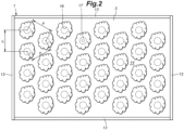
- the setting plate 3 has a plurality of holes 16 penetrating therethrough in the thickness direction.
- Each hole 16 may be formed in a circular shape.
- the holes 16 are spaced apart from each other at a prescribed pitch P.
- the pitch P may be set, for example, to 50 mm to 300 mm.
- the holes 16 may be arranged at the vertices of equilateral triangles when viewed from above.
- the holes 16 may be arranged at the vertices of squares when viewed from above.
- a holding material 17 for holding the plant C may be fitted into each hole 16.
- the holding material 17 may be made of a material that is flexible and permeable.
- the holding material 17 may be made of, for example, urethane foam or rock wool.
- the holding material 17 has a through hole for the plant C to pass through. The plant C may be held in the hole 16 via the holding material 17.
- the light source 4 is provided on a lower surface of the ceiling panel 12.
- the light source 4 may be composed of LEDs.
- the LEDs may have a far-red to blue wavelength range.
- the LEDs may include red LEDs and blue LEDs.
- the light source 4 may also be composed of other artificial light sources such as laser diodes (LDs), cold cathode fluorescent lamps (CCFLs), fluorescent lights, and the like.
- the light source 4 emits light downward, that is, toward the setting plate 3.
- the illuminometer 5 may be composed of a photon sensor that measures a light intensity (photon flux density) [ ⁇ mol/m 2 /s] in the cultivation chamber 14. Further, the illuminometer 5 may be composed of a general illuminometer such as a lux meter for which correlation with the photon sensor has been confirmed.
- the illuminometer 5 includes a plurality of first illuminometers 5A provided on the lower surface of the ceiling panel 12 and a plurality of second illuminometers 5B provided on at least one of the ceiling panel 12 and the sidewall panels 13. Each first illuminometer 5A is arranged so as to face vertically downward.
- Each second illuminometer 5B is arranged so as to be inclined at an angle of 5 to 85 degrees with respect to the vertical downward direction.
- the illuminometer 5 measures reflected light emitted from the light source 4 and reflected by the setting plate 3, the sidewall panels 13, the ceiling panel 12, and the plants C set on the setting plate 3.
- the nutritious liquid pool 11 is connected to a nutritious liquid tank 21 via a circulation path 22.
- a nutritious liquid is stored in the nutritious liquid tank 21.
- the nutritious liquid is a solution containing nutrients necessary for the growth of the plants C.
- the circulation path 22 is provided with a pump 23 that transports the nutritious liquid, and a nutritious liquid adjustment device 24 for adjusting the nutritious liquid.
- the nutritious liquid adjustment device 24 adjusts the values of electrical conductivity (EC) and pH of the nutritious liquid.
- the cultivation device 1 further includes a CO 2 supply device 26 and an air conditioner 27.
- the CO 2 supply device 26 is connected to the case 2 and supplies carbon dioxide to the cultivation chamber 14.
- the air conditioner 27 is connected to the case 2 and regulates the temperature, humidity, and airflow (wind speed) of the cultivation chamber 14.
- the cultivation device 1 may also include a camera 28 that captures images in the cultivation chamber 14.
- the camera 28 may be provided, for example, on the ceiling panel 12, and may capture images of the plants C on the setting plate 3.
- the controller 6 is an arithmetic operation device including a microprocessor (MPU), non-volatile memory, volatile memory, and an interface.
- the controller 6 realizes various applications as the microprocessor executes programs stored in the non-volatile memory.
- the controller 6 controls the power supply to the light source 4 and controls the light intensity of the light source 4.
- the controller 6 acquires the light intensity of the reflected light based on a signal from the illuminometer 5.
- the controller 6 also controls the pump 23, the nutritious liquid adjustment device 24, the CO 2 supply device 26, and the air conditioner 27.
- the controller 6 may be connected to the light source 4, the illuminometer 5, the pump 23, the nutritious liquid adjustment device 24, the CO 2 supply device 26, the air conditioner 27, and the camera 28 via a network such as the Internet.
- the controller 6 may acquire the images captured by the camera 28 and control each device based on the images.
- the plants C cultivated in the cultivation device 1 may be any plants that have leaves and can be cultivated hydroponically, and may be crops such as leafy vegetables, for example.
- the leafy vegetables are vegetables the leaves of which are edible. Examples of the plants C include lettuce, spinach, komatsuna, bok choy, nozawana, and potherb mustard.
- the plants C may be leaf lettuce such as frill lettuce, sunny lettuce, wine dress, and green leaf.
- the plants C may also be aromatic herbs, medicinal herbs, tobacco, wasabi, and hemp.
- the present invention can be applied to crude drugs made from root vegetables such as Panax ginseng.
- the plants C are set in the respective holes 16 of the setting plate 3 in a state where the plants C have grown to seedlings by a seeding process, a greening process, and a raising seedling process.
- Each plant C is held in the corresponding hole 16 such that the stem and leaves thereof are arranged in the cultivation chamber 14 and the roots thereof are arranged below the setting plate 3.
- the roots of each plant C extend into the nutritious liquid in the pool.
- the plants C absorb the nutrients from the nutritious liquid in the pool and grow by absorbing light emitted from the light source 4. As the plants C grow, the leaves thereof extend and the mass thereof increases in the cultivation chamber 14.
- the controller 6 controls the light source 4, the pump 23, the nutritious liquid adjustment device 24, the CO 2 supply device 26, and the air conditioner 27, thereby maintaining the light intensity, the temperature, humidity, wind speed, air volume, and CO 2 concentration in the cultivation chamber 14, the values of EC and pH of the nutritious liquid, and the nutritious liquid circulation flow to satisfy prescribed cultivation conditions.
- the plants C may be harvested after a prescribed period from the setting thereof.
- the conditions of the cultivation device 1 are, for example, as shown in the following Table 1.
- Table 1 Item unit condition emission photosynthetic effective photon flux density ⁇ mol/m 2 /sec 150-250 temperature of cultivation shelf °C 20-25 humidity of cultivation shelf % 70-90 CO 2 concentration of cultivation shelf ppm 1000-1500 EC of nutritious liquid mS/cm 0.8-2.2 pH of nutritious liquid 6.0-6.5 wind speed of cultivation shelf m/sec 0.2-1.0 nutritious liquid circulation flow L/min 2.0-9.0
- the controller 6 estimates the mass of the plant C at any time in the future by executing a growth state estimation process of the plant C.
- the growth state estimation process of the plant C is based on a growth state estimation method of the plant C.
- the growth state estimation process of the plant C includes a first step (S1) of acquiring a first state quantity based on a light intensity acquired by the illuminometer 5, the first state quantity corresponding to light energy absorbed by the plant C from a start of setting thereof to a first time; a second step (S2) of estimating, as first mass, mass of the plant C at the first time based on the first state quantity using a first model that defines a relationship between the first state quantity and the mass of the plant C; a third step (S3) of estimating, as second mass, the mass of the plant C at the first time based on an elapsed time from the start of setting to the first time using a second model that defines a relationship between the elapsed time from the start of setting and the mass of the plant C; a fourth step (S4) of correcting a fitting parameter of the second model such that a difference between the second mass and the first mass is equal to or less than a prescribed first threshold and thereby creating a corrected second model;
- the first state quantity S h1 is a first state quantity calculated based on the first illuminometers 5A
- the first state quantity S y1 is a first state quantity calculated based on the second illuminometers 5B.
- only one of S h1 and S y1 may be used as the first state quantity.
- the controller 6 receives the light intensity measured by the first illuminometers 5A and the second illuminometers 5B at prescribed time intervals.
- the time intervals may be, for example, 1 hour, 12 hours, 24 hours, and the like.
- the first state quantity S ht at any time t after the setting can be expressed by the following Formula (1) using a light intensity P h [ ⁇ mol/m 2 /sec] acquired by the first illuminometers 5A at time t.
- S ht ⁇ 0 t 1 ⁇ P h P h 0 dt
- P h0 [ ⁇ mol/m 2 /sec] represents a light intensity acquired by the first illuminometers 5A in a blank state where no plant C is set on the setting plate 3.
- the first state quantity S yt can be expressed by the following Formula (2) using a light intensity P y [ ⁇ mol/m 2 /sec] acquired by the second illuminometers 5B at any time t after the setting.
- S yt ⁇ 0 t 1 ⁇ P y P y 0 dt
- P y0 [ ⁇ mol/m 2 /sec] represents a light intensity acquired by the second illuminometers 5B in the blank state where no plant C is set on the setting plate 3.
- the controller 6 acquires the first state quantities S h1 , S y1 corresponding to the light energy absorbed by the plant C from the start of setting to the first time t 1 by substituting the first time t 1 for time t in Formulae (1) and (2).
- the above Formulae (1) and (2) are created based on the following concept.
- the plants C have a lower optical reflectance than the ceiling panel 12, the sidewall panels 13, and the setting plate 3 that define the cultivation chamber 14. Accordingly, when the plants C are set on the setting plate 3, the light intensity measured by the illuminometer 5 decreases. Furthermore, as the plants C grow, the area of the setting plate 3 covered with the plants C increases, so that the light intensity measured by the illuminometer 5 further decreases. Accordingly, the difference between the light intensity in the blank state where no plant C is set on the setting plate 3 and the light intensity at a certain time after the plants C are set on the setting plate 3 is considered to correspond to the light energy quantity absorbed by the plants C. The value acquired by integrating this difference over the period from the setting to the first time is considered to correspond to the quantity of the light energy absorbed by the plants C in the period from the setting to the first time.
- the controller 6 estimates, as the first mass, the mass of the plant C at the first time based on the first state quantity using the first model that defines the relationship between the first state quantity and the mass of the plant C.
- the first model is expressed by the following Formula (3) in the present embodiment.
- the first model is an empirical Formula based on the result of the past cultivation.
- w represents the mass [g] of each plant C at time t
- pitch represents a pitch [mm] between the holes 16, and " ⁇ ", “ ⁇ ”, “ ⁇ ”, “ ⁇ 1”, and “ ⁇ 2" represent prescribed parameters.
- the parameters “ ⁇ ”, “ ⁇ ”, “ ⁇ ”, “ ⁇ 1”, and “ ⁇ 2” vary depending on the type and variety of the plant C, the geometry of the cultivation device 1, and the cultivation conditions.
- Pitch0 represents a reference pitch, for example 200 mm or 150 mm.
- Pitch0 may be a pitch in a preliminary test (preliminary cultivation) for determining each parameter of Formula (3).
- Formula (3) shows that the mass w of each plant C at time t is affected by the mass of each plant C at the time of setting, the pitch P, and the first state quantity corresponding to the light energy absorbed by the plant C by time t.
- the mass W of the plant C may be a total mass W T that is the mass of the whole of the plant C, or an edible portion mass W E that is the mass of an edible portion of the plant C.
- the edible portion mass W E and the total mass W T have the following relationship represented by Formula (4) (third model).
- W E ⁇ ⁇ W T
- ⁇ is a coefficient determined by the type and variety of the plant C.
- the total mass W T of the plant C is the mass of the whole of the plant C including roots, a stem, and leaves.
- the edible portion mass W E of the plant C is the mass of the portion used for the edible purpose.
- Each coefficient " ⁇ ”, “ ⁇ ”, “ ⁇ ”, “ ⁇ ”, “ ⁇ 1 ", and “ ⁇ 2 " in Formulae (3) and (4) may be set based on the result of the preliminary cultivation in which the plant C of the same type is cultivated using the cultivation device 1.
- Each coefficient may be provided to the controller 6 from a database that gathers the past results of the cultivation.
- the controller 6 can acquire the edible portion mass W E of each plant C at the first time t 1 without directly weighing the plant C. Based on the relationship in Formula (4), the controller 6 may acquire the total mass W T of each plant C at the first time t 1 instead of the edible portion mass W E of each plant C at the first time t 1 .
- the controller 6 estimates, as the second mass, the mass of the plant C at the first time from the elapsed time from the start of setting to the first time using the second model that defines the relationship between the elapsed time from the start of setting to the first time.
- the second model is expressed by the following Formulae (5) to (13).
- the second model is an empirical Formula based on the past cultivation result and is created using Runge-Kutta method.
- Wn is the mass [g] of the nth plant C (the plant C on the nth day), " ⁇ 1 " and “ ⁇ 2 " are fitting parameters, and "g", "n”, “ ⁇ ⁇ “, and “Dx Pitch0 " are prescribed parameters.
- Each parameter of the second model varies depending on the type and variety of the plant C, the geometry of the cultivation device 1, and the cultivation conditions. Each parameter is set based on the result of the preliminary cultivation. Each parameter may be provided from a database that gathers the result of the preliminary cultivation.
- “Dx” is a planar saturation time, and represents the time required for the leaves of the plants C to completely cover an upper surface of the setting plate 3 and for the measurement value of the illuminometer 5 to become constant.
- “Dx Pitch0 " is a planar saturation time acquired when the preliminary test (preliminary cultivation) for determining each parameter is executed at a standard pitch (for example, 200 mm or 150 mm).
- the controller 6 corrects the fitting parameters of the second model such that the difference between the second mass and the first mass is equal to or less than the prescribed first threshold, thereby creating the corrected second model.
- the corrected second model is created by correcting the fitting parameters ⁇ 1 and ⁇ 2 in Formula (5).
- the fitting parameters ⁇ 1 and ⁇ 2 may be set such that the difference between the second mass calculated by the corrected second model and the first mass is minimized. In a case where the difference between the second mass calculated using the second model before correction and the first mass is equal to or less than the prescribed first threshold, the change in the fitting parameters ⁇ 1 and ⁇ 2 may be omitted.
- the controller 6 estimates the mass of the plant C at the second time after the first time using the corrected second model. For example, in a case where the setting period is 20 days, the controller 6 may execute the growth state estimation process every day and estimate the mass of the plant C for each day after the day of execution, or the mass of the plant C on the 20th day.
- the mass estimated in the fifth step may be the total mass W T or the edible portion mass W E of the plant C.
- the controller 6 estimates the mass of the plant C on the last day of the setting period, that is, on the target harvest day, and controls the light source 4 based on the estimated mass on the target harvest day. For example, in a case where the mass of the plant C on the target harvest day is equal to or less than a target mass, the controller 6 may increase the light intensity of the light source 4 or lengthen the light emission time thereafter. In a case where the mass of the plant C on the target harvest day is greater than the target mass, the controller 6 may advance the target harvest day. The controller 6 may display the estimation value of the mass of the plant C in the future and the target harvest day on a display.
- the mass of the plant C is correlated with the quantity of absorbed light energy, it is possible to estimate, as the first mass, the mass of the plant C at the first time based on the first state quantity using the first model. Further, since the mass of the plant C is correlated with the elapsed time from the setting, it is possible to estimate, as the second mass, the mass of the plant C at the first time using the second model. By correcting the second model such that the difference between the second mass and the first mass is equal to or less than the first threshold, it is possible to acquire the corrected second model that takes into account the growth state of the plant C at the first time. By using the corrected second model acquired in this way, it is possible to estimate the mass of the plant C at any time in the future with high accuracy.
- Frill lettuce was cultivated using the cultivation device 1.
- the seeding process, the greening process, and the raising seedling process were executed using seeds of frill lettuce (commercially available products, Nakahara Seed Co., Ltd., model number: L-121). After the raising seedling process was completed, the seedlings were used for the setting process in the cultivation device 1.
- the seeding process was executed for two days, the greening process was executed for six days, the raising seedling process was executed for eight days, and the setting process was executed for twenty days.
- the light source 4 of the cultivation device 1 was composed of LEDs. The light source 4 was turned on continuously for 18 hours a day and was turned off for the remaining 6 hours. Other conditions were shown in the following Table 2.
- Table 2 Item unit condition emission photosynthetic effective photon flux density ⁇ mol/m 2 /sec 220 ⁇ 10 temperature of cultivation shelf °C 22 ⁇ 2 humidity of cultivation shelf % 80 ⁇ 5 CO 2 concentration of cultivation shelf ppm 1200 ⁇ 100 EC of nutritious liquid mS/cm 2.0 ⁇ 0.2 pH of nutritious liquid - 6.3 ⁇ 0.1 wind speed of cultivation shelf m/sec 0.5 ⁇ 0.2 nutritious liquid circulation flow L/min 8 ⁇ 0.1 (the relationship between the total mass and the edible portion mass of the plant)
- frill lettuce was cultivated three times in the setting process. Further, using the setting plate 3 shown in Figure 2 in which the pitch of the holes 16 is 150 mm, frill lettuce was cultivated once in the setting process. During the setting process, the total mass W T and the edible portion mass W E of randomly selected frill lettuce were weighed every day. The result is shown in Figure 5 . From Figure 5 , it is confirmed that there is a linear correlation between the total mass and the edible portion mass during the setting process regarding frill lettuce. Furthermore, no change was observed in the relationship between the total mass and the edible portion mass when the pitch was 150 mm and when the pitch was 200 mm.
- the ratio of the edible portion mass to the total mass was substantially 0. 86.
- the determination coefficient (R 2 ) of the total mass and the edible portion mass in the regression analysis was equal to or greater than 0. 98. Further, in a case where four cultivation results were combined, the determination coefficient of the total mass and the edible portion mass in the regression analysis was equal to or greater than 0. 99.
- a linear correlation between the total mass and the edible portion mass in the setting process was confirmed in frill lettuce, bok choy, wine dress, and potherb mustard.
- the results of frill lettuce, bok choy, wine dress, and potherb mustard suggest that there is a linear correlation between the total mass and the edible portion mass in the setting process in other plants having leaves of different shapes or colors. Accordingly, the linear correlation between the total mass and the edible portion mass in the setting process can be applied to leaf lettuce such as sunny lettuce and green leaf, and leafy vegetables other than leaf lettuce.
- the preliminary cultivation of frill lettuce in the setting process was executed using the setting plate 3 having the holes 16 the pitch of which is 200 mm.
- the light intensity detected by the first illuminometers 5A and the second illuminometers 5B was acquired every day. Further, the edible portion mass W E of frill lettuce randomly sampled every day was measured using a weighing scale.
- Figure 9 shows the edible portion mass W E of frill lettuce relative to the elapsed time from the start of setting.
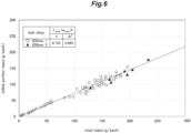
- the actual measurement values in Figure 9 were approximated by the first model (Formula (3)), and " ⁇ ", " ⁇ ", “ ⁇ ”, “ ⁇ 1”, and “ ⁇ 2" in Formula 3 were determined.
- the main cultivation of frill lettuce was executed using the cultivation device 1, and the effectiveness of the first model, the second model, and the corrected second model was confirmed.
- the pitch was set to 200 mm or 150 mm, and other conditions were the same as those in the preliminary cultivation described above.
- the angle of the second illuminometers 5B relative to the vertical downward direction was set to 5 degrees.
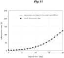
- Figure 11 shows an estimation curve of the edible portion mass and the actual measurement value of the edible portion mass in a case where the pitch is 200 mm.
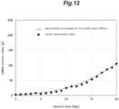
- Figure 12 shows an estimation curve of the edible portion mass and the actual measurement value of the edible portion mass in a case where the pitch is 150 mm. From the results of Figures 11 and 12 , it is confirmed that the estimation value of the edible portion mass acquired from the first model shows high-level agreement with the actual measurement value. It is also confirmed that the estimation value of the edible portion mass can be acquired with high accuracy even if the pitch changes.
- the growth state estimation process was executed based on the result acquired from the main cultivation, and the corrected second model was created every day to acquire the edible portion mass W E of frill lettuce 20 days after the start of setting.
- Figure 13 shows the estimation value in a case where the pitch is 200 mm
- Figure 14 shows the estimation value in a case where the pitch is 150 mm. From Figures 13 and 14 , it is confirmed that the estimation values based on the corrected second model substantially match the actual measurement values.
- the difference ⁇ W between the expected mass W n after prescribed time from the start of setting acquired by the growth state estimation process at any time and the expected mass W n-1 acquired the last time may be calculated.
- W n may be used for the current expected mass in a case where the calculated difference ⁇ W is equal to or more than a prescribed determination value
- W n-1 may be used for the current expected mass in a case where the calculated difference ⁇ W is less than the prescribed determination value.
Landscapes
- Life Sciences & Earth Sciences (AREA)
- Environmental Sciences (AREA)
- Biodiversity & Conservation Biology (AREA)
- Botany (AREA)
- Ecology (AREA)
- Forests & Forestry (AREA)
- Cultivation Of Plants (AREA)
Applications Claiming Priority (2)
| Application Number | Priority Date | Filing Date | Title |
|---|---|---|---|
| JP2022035175A JP7807263B2 (ja) | 2022-03-08 | 2022-03-08 | 生育状態推定方法及び栽培装置 |
| PCT/JP2023/008600 WO2023171673A1 (ja) | 2022-03-08 | 2023-03-07 | 生育状態推定方法及び栽培装置 |
Publications (2)
| Publication Number | Publication Date |
|---|---|
| EP4491010A1 true EP4491010A1 (de) | 2025-01-15 |
| EP4491010A4 EP4491010A4 (de) | 2026-04-15 |
Family
ID=87935180
Family Applications (1)
| Application Number | Title | Priority Date | Filing Date |
|---|---|---|---|
| EP23766849.6A Pending EP4491010A4 (de) | 2022-03-08 | 2023-03-07 | Wachstumsstatusschätzverfahren und kultivierungsvorrichtung |
Country Status (4)
| Country | Link |
|---|---|
| US (1) | US20250176470A1 (de) |
| EP (1) | EP4491010A4 (de) |
| JP (1) | JP7807263B2 (de) |
| WO (1) | WO2023171673A1 (de) |
Family Cites Families (6)
| Publication number | Priority date | Publication date | Assignee | Title |
|---|---|---|---|---|
| JP4243014B2 (ja) | 2000-12-01 | 2009-03-25 | 株式会社荏原製作所 | 植物の生育度測定装置 |
| JP2008076346A (ja) | 2006-09-25 | 2008-04-03 | Ebara Corp | 植物の生育度測定装置及び生育度測定方法 |
| WO2015093054A1 (ja) | 2013-12-20 | 2015-06-25 | 千代田化工建設株式会社 | 作物の生育状態判別方法、生育方法並びに作物生育装置および植物工場 |
| JP2015223101A (ja) | 2014-05-27 | 2015-12-14 | 日本電気株式会社 | 植物状態判定装置、植物状態判定方法及び植物状態判定プログラム |
| CN107423530A (zh) | 2017-09-08 | 2017-12-01 | 沈阳农业大学 | 一种番茄实时重量测量系统及其植株生长模型计算方法 |
| JP2019103452A (ja) | 2017-12-13 | 2019-06-27 | 千代田化工建設株式会社 | 植物栽培システムおよび植物栽培方法 |
-
2022
- 2022-03-08 JP JP2022035175A patent/JP7807263B2/ja active Active
-
2023
- 2023-03-07 EP EP23766849.6A patent/EP4491010A4/de active Pending
- 2023-03-07 US US18/843,470 patent/US20250176470A1/en active Pending
- 2023-03-07 WO PCT/JP2023/008600 patent/WO2023171673A1/ja not_active Ceased
Also Published As
| Publication number | Publication date |
|---|---|
| EP4491010A4 (de) | 2026-04-15 |
| US20250176470A1 (en) | 2025-06-05 |
| WO2023171673A1 (ja) | 2023-09-14 |
| JP7807263B2 (ja) | 2026-01-27 |
| JP2023130726A (ja) | 2023-09-21 |
Similar Documents
| Publication | Publication Date | Title |
|---|---|---|
| EP3661349B1 (de) | Dimmverfahren für konstante lichtintensität | |
| Bugbee et al. | Exploring the limits of crop productivity: I. Photosynthetic efficiency of wheat in high irradiance environments | |
| EP3782457B1 (de) | Pflanzenzuchtverfahren unter verwendung von uv | |
| US20160000020A1 (en) | Cultivation system, cultivation program, and cultivation method | |
| ES2573856T3 (es) | Método y aparato para detectar la aparición de estrés y la recuperación del estrés en materia que contiene clorofila | |
| US20210239608A1 (en) | Device for observing water content, method for observing water content, and cultivation device | |
| Houshmandfar et al. | Modelling stomatal conductance of wheat: An assessment of response relationships under elevated CO2 | |
| EP4491010A1 (de) | Wachstumsstatusschätzverfahren und kultivierungsvorrichtung | |
| Liu et al. | Characteristics and influencing factors of carbon fluxes in winter wheat fields under elevated CO2 concentration | |
| Singh et al. | An experimental study on GREENBOX technology: Feasibility and performance | |
| JP6807169B2 (ja) | 植物栽培装置及び植物栽培方法 | |
| KR101316593B1 (ko) | 식물생육 조절장치 | |
| KR102231425B1 (ko) | 다년생 작물 재배 시스템 | |
| WO2012102372A1 (ja) | 植物栽培方法及び植物栽培装置 | |
| Tan et al. | Responses of irrigated winter wheat yield in North China to increased temperature and elevated CO2 concentration | |
| JP2017212947A5 (de) | ||
| Jolliet et al. | Tomato yield in greenhouses related to humidity and transpiration | |
| US9247688B1 (en) | Nutrient blend optimization system | |
| KR102768001B1 (ko) | 스마트 재배 환경 미러링 시스템 | |
| JP7516928B2 (ja) | 樹木栽培方法及び樹木栽培システム | |
| JPS6255025A (ja) | 植物栽培装置 | |
| KR20220032673A (ko) | 스마트 인삼 수경재배시스템 | |
| JP2022161489A (ja) | 形質変化推定システム及び自動栽培システム | |
| Yoshihara et al. | N2O emission from a tomato rockwool culture is highly responsive to photoirradiation conditions | |
| Nadhiroh et al. | Effects of Plant Spacing on Canopy Light Interception, Photosynthetic Parameters, and Yield in Eggplant (Solanum melongena L.) |
Legal Events
| Date | Code | Title | Description |
|---|---|---|---|
| STAA | Information on the status of an ep patent application or granted ep patent |
Free format text: STATUS: THE INTERNATIONAL PUBLICATION HAS BEEN MADE |
|
| PUAI | Public reference made under article 153(3) epc to a published international application that has entered the european phase |
Free format text: ORIGINAL CODE: 0009012 |
|
| STAA | Information on the status of an ep patent application or granted ep patent |
Free format text: STATUS: REQUEST FOR EXAMINATION WAS MADE |
|
| 17P | Request for examination filed |
Effective date: 20241008 |
|
| AK | Designated contracting states |
Kind code of ref document: A1 Designated state(s): AL AT BE BG CH CY CZ DE DK EE ES FI FR GB GR HR HU IE IS IT LI LT LU LV MC ME MK MT NL NO PL PT RO RS SE SI SK SM TR |
|
| DAV | Request for validation of the european patent (deleted) | ||
| DAX | Request for extension of the european patent (deleted) | ||
| A4 | Supplementary search report drawn up and despatched |
Effective date: 20260316 |
|
| RIC1 | Information provided on ipc code assigned before grant |
Ipc: A01G 7/00 20060101AFI20260310BHEP Ipc: A01G 7/04 20060101ALI20260310BHEP Ipc: A01G 9/26 20060101ALI20260310BHEP Ipc: A01G 31/02 20060101ALI20260310BHEP |