EP4487808A1 - Leistungsvorrichtung, chirurgischer roboter und gelenkverfahren - Google Patents
Leistungsvorrichtung, chirurgischer roboter und gelenkverfahren Download PDFInfo
- Publication number
- EP4487808A1 EP4487808A1 EP23762789.8A EP23762789A EP4487808A1 EP 4487808 A1 EP4487808 A1 EP 4487808A1 EP 23762789 A EP23762789 A EP 23762789A EP 4487808 A1 EP4487808 A1 EP 4487808A1
- Authority
- EP
- European Patent Office
- Prior art keywords
- rotating component
- component
- input disk
- rotating
- coupled
- Prior art date
- Legal status (The legal status is an assumption and is not a legal conclusion. Google has not performed a legal analysis and makes no representation as to the accuracy of the status listed.)
- Pending
Links
Images



Classifications
-
- A—HUMAN NECESSITIES
- A61—MEDICAL OR VETERINARY SCIENCE; HYGIENE
- A61B—DIAGNOSIS; SURGERY; IDENTIFICATION
- A61B34/00—Computer-aided surgery; Manipulators or robots specially adapted for use in surgery
- A61B34/30—Surgical robots
-
- A—HUMAN NECESSITIES
- A61—MEDICAL OR VETERINARY SCIENCE; HYGIENE
- A61B—DIAGNOSIS; SURGERY; IDENTIFICATION
- A61B18/00—Surgical instruments, devices or methods for transferring non-mechanical forms of energy to or from the body
-
- A—HUMAN NECESSITIES
- A61—MEDICAL OR VETERINARY SCIENCE; HYGIENE
- A61B—DIAGNOSIS; SURGERY; IDENTIFICATION
- A61B34/00—Computer-aided surgery; Manipulators or robots specially adapted for use in surgery
- A61B34/30—Surgical robots
- A61B2034/302—Surgical robots specifically adapted for manipulations within body cavities, e.g. within abdominal or thoracic cavities
-
- A—HUMAN NECESSITIES
- A61—MEDICAL OR VETERINARY SCIENCE; HYGIENE
- A61B—DIAGNOSIS; SURGERY; IDENTIFICATION
- A61B90/00—Instruments, implements or accessories specially adapted for surgery or diagnosis and not covered by any of the groups A61B1/00 - A61B50/00, e.g. for luxation treatment or for protecting wound edges
- A61B90/08—Accessories or related features not otherwise provided for
- A61B2090/0807—Indication means
- A61B2090/0808—Indication means for indicating correct assembly of components, e.g. of the surgical apparatus
Definitions
- the subject matter herein generally relates to robots, in particular to a power apparatus, a surgical robot, and an engaging method.
- Minimally invasive surgery refers to a surgical technique that utilizes modern medical instruments such as laparoscopes, thoracoscopes, and related equipment to perform operations inside the human body. Compared to traditional surgical methods, minimally invasive surgery offers advantages such as smaller incisions, less pain, and faster recovery.
- the present disclosure provides a power apparatus, a surgical robot, and an engaging method that can accurately identify the drive-coupling state between the power apparatus and surgical instrument, thereby precisely executing the surgeon's instructions and avoiding unexpected swings of the instrument joints.
- the present disclosure provides a power apparatus of a surgical robot.
- the power apparatus comprises a first housing; a rotating component rotatably provided on the first housing, comprising a target portion and an axial coupling end, wherein the coupling end is configured to be coupled with a drive-input interface providing torque for a surgical instrument; an axial biasing component configured to provide an elastic bias towards the surgical instrument for the rotating component; a first detection component configured to detect a position of the rotating component in an axial direction of the rotating component; a second detection component configured to be aligned with the target portion when the rotating component is rotated to a zero position; and a controller configured to: rotate the rotating component until the target portion is detected by the second detection component before mounting the drive-input interface; and when a detected portion of the rotating component is located at a position further from the surgical instrument than a preset position, rotate the rotating component in a preset manner so as to move the rotating component along the axial direction of the rotating component to the preset position.
- the drive-input interface comprises a first input disk provided on the surgical instrument, and the first input disk and the rotating component are coupled by engagement of concave and convex features on end surfaces facing each other; the controller is configured to: determine whether the first input disk is coupled with the rotating component based on a detection result from the first detection component after the surgical instrument is mounted to the power apparatus.
- the power apparatus further comprises an adapter assembly, wherein the adapter assembly comprises a second housing detachably mounted to the first housing and a second input disk rotatably provided on the second housing; the drive-input interface comprises the second input disk, and the second input disk is capable of being coupled with the rotating component by engagement of concave and convex features on end surfaces facing each other to transmit torque between the rotating component and the surgical instrument; the controller is configured to: determine whether the second input disk is coupled with the rotating component based on a detection result from the first detection component after the second housing is mounted to the power apparatus.
- the adapter assembly comprises a second housing detachably mounted to the first housing and a second input disk rotatably provided on the second housing
- the drive-input interface comprises the second input disk
- the second input disk is capable of being coupled with the rotating component by engagement of concave and convex features on end surfaces facing each other to transmit torque between the rotating component and the surgical instrument
- the controller is configured to: determine whether the second input disk is coupled with the rotating component
- he second input disk and the first input disk provided on the surgical instrument are coupled by engagement of concave and convex features on end surfaces facing each other, and the second input disk has a freedom along an axial direction of the second housing; the controller is configured to: determine whether the first input disk is coupled with the second input disk based on a detection result from the first detection component after the second input disk is coupled with the rotating component and the surgical instrument is mounted to the power apparatus.
- a detection end of the first detection component is provided on a side of the rotating component that is further from the surgical instrument, and there is a gap along an axial direction of the rotating component between the detection end of the first detection component and the rotating component.
- the first detection component is configured to detect whether the detected portion of the rotating component is sensed; the controller is configured to: determine that the drive-input interface is not coupled with the rotating component when the first detection component senses the detected portion of the rotating component.
- the first detection component is configured to detect a distance between the first detection component and the detected portion; the controller is configured to: determine that the drive-input interface is not coupled with the rotating component when the first detection component detects that the distance between the first detection component and the rotating component is less than a preset distance.
- the power apparatus further comprises an adapter assembly detachably mounted to the first housing, wherein the adapter assembly is configured to transmit torque between the rotating component and the surgical instrument; the controller is configured to: control the rotating component to be rotated until the target portion is detected by the second detection component when the adapter assembly is mounted to the first housing and the first detection component detects that the adapter assembly is drivingly engaged with the rotating component.
- the power apparatus further comprises an adapter assembly, wherein the adapter assembly comprises a second input disk, and the surgical instrument comprises a first input disk coupled with the rotating component via the second input disk;
- the controller is configured to: control the rotating component to be rotated in a preset first manner when the second input disk is mounted to the rotating component and not coupled with the rotating component, and interrupt rotation of the rotating component in the preset first manner when the rotating component is rotated to be coupled with the second input disk; and/or control the rotating component to be rotated in a preset second manner when the rotating component is coupled with the second input disk and the first input disk is mounted to the second input disk and not coupled with the rotating component, and interrupt rotation of the rotating component in the preset second manner when the rotating component is rotated to be coupled with the first input disk.
- the rotating component comprises a first rotating component and a second rotating component each corresponding to one of the second input disk and one of the first input disk;
- the controller is configured to: control the first rotating component to be rotated in a preset third manner when the first rotating component is coupled with the second input disk corresponding to the first rotating component and the first input disk corresponding to the first rotating component is mounted to the second input disk corresponding to the first rotating component and not coupled with the first rotating component, interrupt the rotation of the first rotating component in the preset third manner when the first rotating component is rotated to be coupled with the first input disk corresponding to the first rotating component, and control the first rotating component to be rotated until the target portion is detected by the second detection component; and control the second rotating component to be rotated in a preset fourth manner when the second rotating component is coupled with the second input disk corresponding to the second rotating component and the first input disk corresponding to the second rotating component is mounted to the second input disk corresponding to the second rotating component and not coupled with the second rotating component, interrupt the rotation of the second rotating component in the prese
- the rotating component comprises a first rotating component and a second rotating component each corresponding to one of the second input disk and one of the first input disk;
- the controller is configured to: control the first rotating component to be rotated in a preset third manner when the first rotating component is coupled with the second input disk corresponding to the first rotating component and the first input disk corresponding to the first rotating component is mounted to the second input disk corresponding to the first rotating component and not coupled with the first rotating component, interrupt the rotation of the first rotating component in the preset third manner when the first rotating component is rotated to be coupled with the first input disk corresponding to the first rotating component, and stop rotating the first rotating component; and control the second rotating component to be rotated in a preset fourth manner when the second rotating component is coupled with the second input disk corresponding to the second rotating component and the first input disk corresponding to the second rotating component is mounted to the second input disk corresponding to the second rotating component and not coupled with the second rotating component, interrupt the rotation of the second rotating component in the preset fourth manner when the second rotating component is rotated to be coupled
- the preset first manner and the preset second manner both comprise scanning by rotation in forward and reverse directions, an angle of unidirectional scanning in the first manner is equal to or less than a first angular threshold, the angle of unidirectional scanning in the second manner is equal to or less than a second angular threshold, and the first angular threshold is greater than the second angular threshold.
- the power apparatus further comprises an indication device, wherein the first housing is provided with a first signal terminal, the adapter assembly comprises a second signal terminal, the surgical instrument comprises a third signal terminal, the indication device is provided on the adapter assembly and electrically connected to the second signal terminal; the second signal terminal is capable of being conductively connected to the first signal terminal after the adapter assembly is mounted to the first housing, and is capable of being conductively connected to the third signal terminal after the surgical instrument is mounted to the adapter assembly; the controller is configured to: switch an indication state of the indication device according to the detection result from the first detection component after the adapter assembly is mounted to the first housing and/or after the surgical instrument is mounted to the adapter assembly.
- an edge of a surface of the second input disk having a concave or convex feature is protruded with multiple first protrusions
- a surface of the second housing facing the surface of the second input disk having the concave or convex feature is protruded with multiple second protrusions
- the second protrusions are configured to restrict rotation of the second input disk when each of the first protrusions is embedded between two second protrusions.
- the present disclosure provides a surgical robot.
- the surgical robot comprises a surgical instrument and the power apparatus according to any one of the aforementioned embodiments.
- the surgical instrument is configured to perform corresponding actions driven by the power apparatus.
- the present disclosure provides a detecting method for the engagement state of a power apparatus of a surgical robot.
- the power apparatus comprises a rotating component comprising an axial coupling end; an axial biasing component configured to provide an elastic bias towards a surgical instrument for the rotating component; a first detection component configured to detect a position of the rotating component in an axial direction of the rotating component.
- the method comprises: determining whether the drive-input interface is coupled with the rotating component based on the detection result from the first detection component, wherein deformation of the axial biasing component is configured to be increased when a drive-input interface providing torque for the surgical instrument is coupled with the rotating component, the drive-input interface is determined to be not coupled with the rotating component when a detected portion of the rotating component is located at a position further from the surgical instrument than a preset position.
- the drive-input interface comprises a first input disk provided on the surgical instrument, and the first input disk and the rotating component are coupled by engagement of concave and convex features on end surfaces facing each other; the method comprise: determining whether the first input disk is coupled with the rotating component based on a detection result from the first detection component after the surgical instrument is mounted to the power apparatus.
- the power apparatus further comprises an adapter assembly, wherein the adapter assembly comprises a second input disk (52) having a axial and a circumferential degrees of freedom, the first input disk and the rotating component are coupled by engagement of concave and convex features on end surfaces facing each other, the second input disk is coupled with a first input disk provided on the surgical instrument by engagement of concave and convex features on end surfaces facing each other; the method comprise: determining whether the first input disk is coupled with the rotating component based on a detection result from the first detection component after the surgical instrument is mounted to the power apparatus; determining whether the second input disk is coupled with the rotating component based on a detection result from the first detection component after the second housing is mounted to the power apparatus.
- the adapter assembly comprises a second input disk (52) having a axial and a circumferential degrees of freedom, the first input disk and the rotating component are coupled by engagement of concave and convex features on end surfaces facing each other, the second input disk is coupled with a first input disk provided on the surgical instrument by engagement
- the first detection component is configured to detect whether a detected portion of the rotating component is sensed.
- the method comprises: determining that the drive-input interface is not coupled with the rotating component when the first detection component senses the detected portion of the rotating component.
- the first detection component is configured to detect a distance between the first detection component and the rotating component.
- the method comprises: determining that the drive-input interface is not coupled with the rotating component when the distance between the first detection component and the rotating component is less than a preset distance.
- the power apparatus further comprises a first signal terminal.
- the method comprises: determining that the drive-input interface is mounted to the power apparatus based on signal indicating conduction of the first signal terminal and the signal terminal of the drive-input interface.
- the power apparatus further comprises an adapter assembly which is provided with a second signal terminal and transmits torque between the rotating component and the surgical instrument.
- the method comprises: determining that the adapter assembly is mounted to the power apparatus based on signal indicating conduction of the first signal terminal and the second signal terminal; and/or determining that the surgical instrument is mounted to the power apparatus based on signal indicating conduction of the first signal terminal and the third signal terminal of the surgical instrument after the adapter assembly is mounted to the power apparatus.
- the power apparatus further comprises an indication device and a first signal terminal
- the adapter assembly comprises a second signal terminal
- the surgical instrument comprises a third signal terminal
- the indication device is provided on the adapter assembly and electrically connected to the second signal terminal
- the second signal terminal is capable of being conductively connected to the first signal terminal after the a adapter assembly is mounted to the power apparatus, and is capable of being conductively connected to the third signal terminal after the surgical instrument is mounted to the adapter assembly.
- the method comprises: switching an indication state of the indication device according to the detection result from the first detection component after the adapter assembly is mounted to the first housing and/or after the surgical instrument is mounted to the adapter assembly.
- the present disclosure provides an engaging method for a power apparatus of a surgical robot.
- the power apparatus comprises a rotating component comprising an axial coupling end; an axial biasing component configured to provide an elastic bias towards a surgical instrument for the rotating component, wherein deformation of the axial biasing component is increased when a drive-input interface providing torque for the surgical instrument is coupled with the rotating component; a first detection component configured to detect a position of the rotating component in an axial direction of the rotating component.
- the engaging method comprises: detecting the position of the rotating component in the axial direction of the rotating component after the drive-input interface is mounted the rotating component of the power apparatus; and rotating the rotating component in a preset manner when a detected portion of the rotating component is located at a position further from the surgical instrument than a preset position so as to move the rotating component along the axial direction of the rotating component to the preset position.
- the power apparatus further comprises a second detection component, and the rotating component is provided with a target portion.
- the engaging method further comprises rotating the rotating component until the target portion is detected by the second detection component before mounting the drive-input interface.
- the drive-input interface comprises a first input disk provided on the surgical instrument, and the first input disk and the rotating component are coupled by engagement of concave and convex features on end surfaces facing each other.
- the power apparatus further comprises an adapter assembly comprising a second input disk having an axial degree of freedom and a circumferential degree of freedom, the second input disk is capable of being coupled with the rotating component by engagement of concave and convex features on end surfaces facing each other, and the second input disk is coupled with a first input disk provided on the surgical instrument by engagement of concave and convex features on end surfaces facing each other;
- the engaging method comprises: mounting the adapter assembly to the power apparatus; detecting the position of the rotating component in the axial direction of the rotating component; rotating the rotating component in a preset first manner when the detected portion of the rotating component is located at the position further from the surgical instrument than the preset position so as to move the rotating component along the axial direction of the rotating component to the preset position; mounting the surgical instrument to the adapter assembly; detecting the position of the rotating component in the axial direction of the rotating component; and rotating the rotating component in a preset second manner when the detected portion of the rotating component is located at the position further from the surgical instrument than the preset
- the power apparatus further comprises a second detection component, and the rotating component is provided with a target portion; the engaging method comprises: controlling rotation of the rotating component until the target portion is detected by the second detection component after the adapter assembly is mounted to the power apparatus and the rotating component is located in the preset position along the axial direction of the rotating component.
- the engaging method further comprises: after rotating the rotating component in a preset first manner, interrupting the rotation of the rotating component in the preset first manner when the rotating component moves to the preset position along the axial direction of the rotating component; and/or after rotating the rotating component in a preset second manner, interrupting the rotation of the rotating component in the preset second manner when the rotating component moves to the preset position along the axial direction of the rotating component.
- the power apparatus further comprises a second detection component, and the rotating component is provided with a target portion;
- the rotating component comprises a first rotating component and a second rotating component each corresponding to one of the second input disk and one of the first input disk;
- the engagement method comprises: controlling the first rotating component to be rotated in a preset third manner when the first rotating component is coupled with the second input disk corresponding to the first rotating component and the first input disk corresponding to the first rotating component is mounted to the second input disk corresponding to the first rotating component and not coupled with the first rotating component, interrupt the rotation of the first rotating component in the preset third manner when the first rotating component is rotated to be coupled with the first input disk corresponding to the first rotating component, and control the first rotating component to be rotated until the target portion is detected by the second detection component; and controlling the second rotating component to be rotated in a preset fourth manner when the second rotating component is coupled with the second input disk corresponding to the second rotating component and the first input disk corresponding to the second rotating component is mounted to the second input disk corresponding to the
- the power apparatus further comprises a second detection component, and the rotating component is provided with a target portion;
- the rotating component comprises a first rotating component and a second rotating component each corresponding to one of the second input disk and one of the first input disk;
- the engagement method comprises: controlling the first rotating component to be rotated in a preset third manner when the first rotating component is coupled with the second input disk corresponding to the first rotating component and the first input disk corresponding to the first rotating component is mounted to the second input disk corresponding to the first rotating component and not coupled with the first rotating component, interrupt the rotation of the first rotating component in the preset third manner when the first rotating component is rotated to be coupled with the first input disk corresponding to the first rotating component, and stop rotating the first rotating component; and controlling the second rotating component to be rotated in a preset fourth manner when the second rotating component is coupled with the second input disk corresponding to the second rotating component and the first input disk corresponding to the second rotating component is mounted to the second input disk corresponding to the second rotating component and not coupled with the second rotating component, interrupt the
- the present disclosure provides a control method for a surgical robot comprising an operating part and a slave device.
- the slave device comprises: multiple rotating components each comprising an axial coupling end; multiple axial biasing components each configured to provide an elastic bias toward a surgical instrument for each of the rotating components, wherein deformations of the axial biasing components are increased when drive-input interfaces providing torque for the surgical instrument are coupled with the rotating components; and multiple first detection components, each configured to detect a position of one of the rotating components in an axial direction of the one of the rotating components.
- the control method comprises: determining whether the drive-input interfaces are coupled with the rotating components based on detection results from the first detection components; and aligning a posture of the operating part with a posture of the slave device after all the drive-input interfaces of the surgical instrument are coupled with corresponding rotating components of the power apparatus.
- the rotating components comprises a first rotating component and a second rotating component each corresponding to a second input disk and a first input disk; before aligning the posture of the operating part with the posture of the slave device and after all the drive-input interfaces of the surgical instrument are coupled with corresponding rotating components of the power apparatus, the control method further comprises: detecting whether the target portion of each of the second rotating components is rotated to be a preset angular range; and aligning the posture of the operating part with the posture of the slave device when the target portion of each of the second rotating component is rotated to be in the preset angular range ( ⁇ ), otherwise, not performing the posture alignment step.
- the power apparatus provided by the present disclosure utilize a first detection component to detect the axial position of a rotating component configured to output torque. This allows for accurately determining the drive-coupling state of the power apparatus based on the detection result from the first detection component after the surgical instrument is mounted. Consequently, the intended movements according to the surgeon's instructions can be precisely executed, and surgical risk caused by unexpected swings of the instrument joints can be avoided.
- distal and proximal are used herein as directional terms commonly used in the field of interventional medical devices, wherein “distal” refers to the end away from the operator during a surgical procedure, and “proximal” refers to the end closer to the operator during the surgical procedure.
- first and second are used only for descriptive purposes and should not be construed as indicating or implying relative importance or implicitly specifying the number of technical features indicated. Thus, features defined as “first” or “second” may explicitly or implicitly include one or more such features. In the description of the invention, the meaning of “multiple” refers to two or more, unless otherwise specifically and explicitly limited.
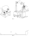
- a surgical robot comprises a master console 1 and a slave device 2.
- the master console 1 comprises an operating part 1a through which the user controls the movement of the slave device 200.
- the master console 1 sends control commands to the slave device 2 to control it, and displays images acquired from the slave device 2.
- the slave device 2 responds to control commands sent by the master console 1 and performs corresponding operations.
- the slave device 2 can also be used to acquire images from inside the body.
- the slave device 2 may include a mechanical arm 21, a power apparatus 100 disposed on the mechanical arm 21, a surgical instrument 200 disposed on the power apparatus 100, and a cannula 22 sheathing the long shaft 210 of the surgical instrument 200.
- the mechanical arm 21 is used to adjust the position of the surgical instrument 200
- the power apparatus 100 is used to drive the surgical instrument 200 to perform corresponding operations.
- the embodiments of the present disclosure are not limited to master-slave surgical robots, and the surgical robot may also adopt a construction that does not distinguish between master and slave devices and integrates operational functions into the slave device.
- the surgical instrument 200 mainly comprises a long shaft 210, an end effector 211, and an instrument drive unit 212.
- the end effector 211 of the surgical instrument 200 is used to be inserted into the body and perform surgical operations and/or acquire images from inside the body through its distal end effector.
- the long shaft 210 of the surgical instrument 200 is inserted into the cannula 22, with its end effector 211 extending out of the cannula 22 and being driven by the power apparatus 100 to perform operations.
- the region of the long shaft 210 of the surgical instrument 200 located within the cannula 22 can be set as a rigid or flexible region according to requirements, and the cannula 22 can also be omitted.
- the slave device 2 may include one or more mechanical arms 21each provided with one or more power apparatus 100, and one or more surgical instruments 200 can be mounted to each power apparatus 100.
- one power apparatus 100 can be connected to one surgical instrument 200, providing the driving force for the surgical instrument 200 to perform related operations.
- one power apparatus 100 can simultaneously be connected to multiple different surgical instruments 200, providing driving force for the multiple surgical instruments 200.
- each surgical instrument 200 comprises multiple first input disks 51, such as 51A-51F.
- Each power apparatus 100 engaged with the surgical instrument 200 further comprises multiple rotating components 10 driven by motors to rotate.
- first input disks 51 are drivingly coupled with rotating components 10 respectively, thereby implementing torque transmission.
- the power apparatus 100 drives the end effector 211 to perform related surgical operations.
- FIG. 3 illustrates a case where the surgical instrument 200 comprises six first input disks 51A-51F. In other embodiments, the number of first input disks may vary.
- Surgical operations may include controlling the distal end of the long shaft 210 to perform deflection, rotation, pitch, and other operations.
- the end effector 211 may be surgical forceps, cautery devices, cutting devices, imaging devices, etc.
- the first input disks 51 are disposed within the instrument housing 213, with the proximal end of the first input disks 51 rotatably connected to the instrument drive unit 212, and the distal end of the first input disks 51 exposed outside the instrument housing 213 and configured to receive driving input from the power apparatus 100, thereby driving the end effector 211 to move. Each first input disk 51 moves independently from other first input disks.
- the following embodiment is described taking an example where the distal end of the instrument housing 213 of the surgical instrument 200 is mounted to the proximal end of the power apparatus 100. Under this circumstance, an instrument channel for the long shaft 210 at the distal end of the surgical instrument 200 to pass through is formed on the power apparatus 100.
- the first input disks 51 of the surgical instrument 200 are located at the distal end of the instrument housing 213, facing the end effector 211, while the rotating components 10 of the power apparatus 100 are located at the proximal end of the power apparatus 100. It should be understood that the present disclosure is also applicable to a case where the proximal end of the instrument housing 213 of the surgical instrument 200 is mounted to the distal end of the power apparatus 100. Under this circumstance, the first input disks 51 of the surgical instrument 200 are located at the proximal end of the instrument housing 213, facing away from the end effector 211, while the rotating components 10 of the power apparatus 100 are located at the distal end of the power apparatus 100.
- the present embodiment provides a power apparatus 100 that mainly comprises a first housing 100a, a rotating component 10, an axial biasing component 20, a first detection component 30, and a controller 40.
- the first housing 100a is used to fix the motor M, and each motor M is drivingly connected to a first input disk 51 and configured to provide a rotational power source for the first input disk 51.
- the rotating component 10 is rotatably disposed in the first housing 100a and comprises an axial coupling end 10S exposed outside the first housing 100a for being engaged with a drive-input interface 50.
- the drive-input interface 50 serving as the power input interface of the surgical instrument 200, can be part of the surgical instrument 200, a component independent from the surgical instrument 200, or part of the power apparatus 100.
- the axial biasing component 20 is configured to provide an elastic bias toward the surgical instrument 200 for the rotating component 10, so that when the drive-input interface 50 is engaged with the rotating component 10, elastic contact can be maintained to achieve stable axial contact.
- the axial biasing component 20 experiences further deformation when the drive-input interface 50 is coupled with the rotating component 10, resulting in increased deformation.
- the axial biasing component 20 adopts a compression spring located on the side of the rotating component 10 further from the surgical instrument 200 (the distal end) than the rotating component 10, fixed to the rotation axis M1 of the motor M, and rotated with the rotation of the rotating component 10. When the rotating component 10 is not pressed, the compression of the axial biasing component 20 is minimal; when the rotating component 10 is pressed down, the compression of the axial biasing component 20 increases.
- the axial biasing component 20 can also adopt other elastic component capable of deformation, such as rubber.
- the axial biasing component 20 can also be disposed on the side of the rotating component 10 closer to the surgical instrument 200 (the proximal end) than the rotating component 10 and adopt a tension spring.
- One end of the axial biasing component 20 is fixed to the rotation axis M1 of the motor M, and the other end is fixed with the rotating component 10, pulling the rotating component 10 toward the surgical instrument 200.
- the extension of the axial biasing component 20 is minimal; when the rotating component 10 is pressed down, the extension of the axial biasing component 20 increases.
- a groove C can be provided at the end of the rotating component 10 to house the tension spring.
- the drive-input interface 50 is not mounted to the rotating component 10.
- the first detection component 30 is configured to detect the position of the rotating component 10 or a certain part of the rotating component 10 in the axial direction of the rotating component 10.
- the controller 40 is configured to determine that the drive-input interface 50 is not coupled with the coupling end 10S of the rotating component 10 when the detected portion of the rotating component 10 is located at a position further from the surgical instrument 200 than a preset position (such as the A0 position shown in FIG. 4A ).
- the rotating component 10 being at the preset position A0 is the critical state of coupling the drive-input interface 50 and the rotating component 10.
- the drive-input interface 50 compresses the axial biasing component 20 to provide torque for the surgical instrument 200. That is to say, the rotating component 10 is at the preset position A0 only when the drive-input interface 50 is coupled with the rotating component 10. Under other circumstances, the rotating component 10 is not at the preset position A0, and the drive-input interface 50 cannot be drivingly connected with the rotating component 10.
- the first detection component 30 can comprise directly measuring the displacement (i.e., position) change of the rotating component 10 along the axial direction of the rotating component 10 or indirectly measuring the deformation of the axial biasing component 20.
- the first detection component 30 detects the position change of the rotating component 10 along the axial direction of the rotating component 10. Specifically, there is a gap between the detection end of the first detection component 30 and the rotating component 10 along the axial direction of the rotating component 10. The detection end of the first detection component 30 is disposed on the side of the rotating component 10 further from the surgical instrument 200 than the rotating component 10, i.e., on the distal side of the rotating component 10.
- the first detection component 30 is a non-contact sensor configured to detect whether the detected portion of the rotating component 10 is sensed.
- the first detection component 30 adopts a proximity sensor.
- the controller 40 is configured to determine that the drive-input interface 50 is not coupled with the rotating component 10 when the first detection component 30 senses the detected portion of the rotating component 10.
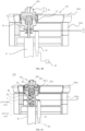
- FIG. 4A it illustrates a schematic diagram of the internal structure of the power apparatus in a coupled state of the surgical instrument.
- FIG. 4B it illustrates a schematic diagram of the internal structure of the power apparatus in an uncoupled state of the surgical instrument according to Embodiment 1 of the present disclosure.
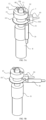
- FIG. 5A shows a schematic diagram of the main structure of a power apparatus.
- the drive-input interface 50 is coupled with the rotating component 10 through the engagement of concave and convex features facing each other.
- the controller 40 determines that the drive-input interface 50 is not coupled with the rotating component 10.
- the rotating component 10 rebounds towards the proximal side by a certain distance, which increases the distance between the first detection component 30 and the rotating component 10.
- the actual position of the rotating component 10 along the axial direction of the rotating component 10 reaches the preset position A0 and cannot be detected by the first detection component 30 anymore.
- the controller 40 determines that the drive-input interface 50 is coupled with the rotating component 10.
- the rotating component 10 has an annular detected portion 101.
- the first detection component 30 is configured to detect whether the detected portion 101 is sensed.
- the controller 40 is configured to determine that the drive-input interface 50 is not coupled with the rotating component 10 when the detected portion 101 is sensed.
- FIG. 5A shows a scenario where the detection end of the first detection component 30 is directly facing the distal surface of the rotating component 10.
- the first detection component 30 is located on one side of the rotating component 10 in the axial direction of the rotating component 10. When the rotating component 10 is pressed to move in a direction that increases the deformation of the axial biasing component 20 (i.e., in a direction opposite to the surgical instrument 200), the distance between the detected portion 101 and the detection end of the first detection component 30 gradually decreases.
- FIG. 5B shows another power apparatus.
- the rotating component 10 has an annular detected portion 101'.
- the first detection component 30 is disposed on the outer side of the rotating component 10 in the radial direction and faces the central axis of the rotating component 10 to detect the annular outer circumferential surface of the detected portion 101'.
- the annular outer circumferential surface has a larger radial dimension than the adjacent outer circumferential surface of the rotating component 10.
- the distance between the detected portion 101' and the detection end of the first detection component 30 gradually decreases.
- the detected portion 101' approaches the first detection component 30, it can be detected by the first detection component 30.
- the detected portion 101' will gradually move away from the detection end of the first detection component 30, and the distance between the detected portion 101' and the detection end of the first detection component 30 will gradually increase.
- the position of the first detection component 30 can be set such that when it detects the detected portion 101' directly opposite to it, the rotating component 10 reaches the preset position A0.
- the controller 40 is configured to determine that the drive-input interface 50 is coupled with the rotating component 10 when the detected portion 101' is detected.
- the detected portion 101' can be the same as the detected portion 101 or can be a different portion from the detected portion 101.
- the first detection component 30 may not adopt a proximity sensor instead of a distance sensor.
- the first detection component 30 is configured to detect the distance between it and the detected portion 101.
- the controller 40 is configured to determine that the drive-input interface 50 is not coupled with the rotating component 10 when the first detection component 30 detects that the distance between it and the rotating component 10 is less than a preset distance; determine that the drive-input interface 50 is coupled with the rotating component 10 when the first detection component 30 detects that the distance between it and the rotating component 10 is equal to the preset distance; and determine that the drive-input interface 50 is not coupled with the rotating component 10 when the first detection component 30 detects that the distance between it and the rotating component 10 is greater than the preset distance.
- the proximity sensor includes but is not limited to capacitive, inductive, and photoelectric sensors, while the distance sensor includes but is not limited to optical sensors, infrared sensors, and ultrasonic sensors.
- an adaptor assembly 300 is provided between the non-sterile power apparatus 100 and the sterile surgical instrument 200.
- the adaptor assembly 300 can serve as part of a sterile barrier isolating the surgical instrument from other parts of the equipment during usage.
- the sterile barrier separates the non-sterile power apparatus 100 and the sterile surgical instrument 200, while the power (such as motor torque output) from the power apparatus 100 is transmitted through the adaptor assembly 300 to the surgical instrument 200, which enables the surgical instrument 200 to perform corresponding surgical operations while ensuring sterile isolation.
- the surgical instrument 200 is provided with at least one first input disk 51
- the adaptor assembly 300 is provided with at least one second input disk 52
- the power apparatus 100 is provided with at least one rotating component 10.
- the number of rotating components 10, the number of first input disks 51 on the surgical instrument 200, and the number of second input disks 52 on the adaptor assembly 300 are equal, allowing the first input disks 51 to be coupled with the rotating components 10 through the second input disks 52 respectively.
- the adaptor assembly 300 specifically includes a second housing 300a detachably mounted the a first housing 100a and multiple second input disks 52, such as 52A-52F, rotatably disposed on the second housing 300a.
- the first input disk 51 and the second input disk 52 form a drive-input interface 50.
- the second input disk 52 serves only as part of the drive-input interface 50.
- the coupling of the first input disk 51, the second input disk 52, and the rotating component 10 in pairs is referred to as the coupling of the drive-input interface 50 with the rotating component 10. If only the second input disk 52 is coupled with the rotating component 10, and the first input disk 51 is not coupled with the second input disk 52, the drive-input interface 50 is still not coupled with the rotating component 10. In this case, the first detection component 3 can still detect the rotating component 10.
- the controller 40 is configured to determine whether the second input disk 52 is coupled with the rotating component 10 based on the detection result from the first detection component 30 after the second housing 300a is mounted to the power apparatus.
- the controller 40 determines whether the first input disk 51 is coupled with the second input disk 52 based on the detection result from the first detection component 30. This allows the detection of the coupling states of both the second input disk 52 on the adaptor assembly 300 and the first input disk 51 on the surgical instrument 200 using only one first detection component 30 for each rotating component 10.
- the coupling end 10S of the rotating component 10 is provided with first coupling features C1, C2
- the lower surface (distal end) of the second input disk 52 is provided with second coupling features D1, D2
- the upper surface (proximal end) of the second input disk 52 is provided with third coupling features E1, E2
- the lower surface (distal end) of the first input disk 51 is provided with fourth coupling features F 1, F2.
- the first coupling features C1, C2 are convex or concave features
- the second coupling features D1, D2 are concave or convex features adaptive to be engaged with the first coupling features C1, C2 correspondingly.
- the third coupling features E1, E2 are convex or concave features and the fourth coupling features F1, F2 are concave or convex features adaptive to be engaged with the third coupling features E1, E2.
- the torque of the rotating component 10 can be transmitted to the first input disk 51.
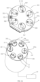
- FIG. 6A illustrates a structural schematic diagram of the power apparatus 100 and its adapter assembly 300.
- the illustrated power apparatus 100 includes six rotating components 10, namely 10A-10F. Multiple rotating components 10 are mounted in the first housing 100a controlled and actuated by controllers 40 respectively.
- Each controller 40 independently controls and drives a surgical instrument 200, for example, rotating components 10 controls operations such as rotation, deflection, pitch, and end effector opening/closing of the surgical instrument 200 respectively.
- the number of controllers 40 can also be varied as needed, for example, one controller 40 may control the rotation of all rotating components 10 in the power apparatus 100.
- a free end of the rotation axis M1 of the motor M extends out of the rotating component 10, protruding further from the rotating component 10 than the coupling end 10S.
- An axis hole H is provided at the axial center of the second input disk 52 of the adapter assembly 300.
- the free end of the rotation axis M1 is inserted into the axis hole H, which implements the pre-alignment of the mounting of the adapter assembly 300 and facilitates the radial alignment between the rotating component 10 and the second input disk 52.
- the axis hole H can be a groove located on the surface of the distal end of the second input disk 52.
- the free end of the rotation axis M1 is fixed with an axis cap M11 and the center of the rotating component 10 is provided with a central hole 10h for the rotation axis M1 to pass through.
- the axis cap M11 is fixed to the free end of the rotation axis M1 and at least partially accommodated within the central hole 10h providing radial restraint to the rotating component 10.
- the rotating component 10 elastically contacts the axis cap M11 in the axial direction.
- the axis cap M11 allows the rotating component 10 to move axially but prevents it from rotating relative to the rotation axis M1.
- the power apparatus can include various signal terminals.
- the first housing 100a of the power apparatus 100 is provided with a first signal terminal P1, which can be conducted by contacting with a signal terminal on the drive-input interface 50.
- the controller 40 is configured to determine that the drive-input interface 50 is mounted to the power apparatus based on the signal indicating conduction between the first signal terminal P1 and the signal terminal of the drive-input interface 50.
- the controller 40 is configured to determine that the adapter assembly 300 is mounted to the first housing 100a based on the signal indicating conduction between the second signal terminal P2 and the first signal terminal P1. After the adapter assembly 300 is mounted to the first housing 100a of the power apparatus 100, the controller 40 is configured to determine that the surgical instrument 200 is mounted to the adapter assembly 300 based on the signal indicating conduction between the third signal terminal P3 of the surgical instrument 200 and the first signal terminal P1.
- the surgical instrument 200 when the surgical instrument 200 is mounted to the first housing 100a of the power apparatus 100, its third signal terminal P3 can be conducted by contacting with the first signal terminal P1.
- the controller 40 is configured to determine that the surgical instrument 200 is mounted to the power apparatus 100 based on the signal indicating conduction between the third signal terminal P3 of the surgical instrument 200 and the first signal terminal P1.
- the power apparatus 100 in the present embodiment further comprises an indication device 301, which can be disposed on the outer wall of the second housing 300a for easy observation. Since the first housing 100a is provided with a first signal terminal P1, the adapter assembly 300 is provided with a second signal terminal P2, and the surgical instrument 200 is provided with s a third signal terminal P3, the indication device 301 is disposed on the adapter assembly 300 and electrically connected to the second signal terminal P2.
- the indication device 301 can be conducted with the detection circuit comprising the first signal terminal through the second signal terminal P2, thereby emitting indication based on the coupling state of the second input disk 52 of the adapter assembly 300 and the first input disk 51 of the surgical instrument 200.
- the indication device 301 can be an indicator light or a loudspeaker, etc.
- the second signal terminal P2 can be conducted with the first signal terminal P1 after the adapter assembly 300 is mounted to the first housing 100a, and can be conducted with the third signal terminal P3 after the surgical instrument 200 is mounted to the adapter assembly 300.
- the power apparatus 100 is provided with a second detection component 60, and a target portion T is disposed on the rotating component 10 correspondingly.
- the target portion T is rotated to be directly opposite to the second detection component 60, thereby determining that the rotating component 10 has returned to the zero position.
- the rotation angle of the rotating component 10 can be determined, which facilitates the subsequent mounting and coupling of the surgical instrument 200.
- the controller 40 is configured to determine that the rotating component 10 is rotated to the zero position when the target portion T is rotated with the rotating component 10 to be detected by the second detection component 60.
- the target portion T can be a through-hole in the axial direction of the rotating component 10.
- the second detection component 60 includes a transmitting end 61 and a receiving end 62 disposed on two sides of the target portion T along the axial direction of the rotating component 10.
- the target portion T is rotated to be between the transmitting end 61 and the receiving end 62; otherwise, it is indicated that the target portion T is not directly opposite to the second detection component 60.
- the target portion T can be disposed on the annular detected portion 101, and the transmitting end 61 and the receiving end 62 are located on two sides of the detected portion 101 along the axial direction of the rotating component 10, clamping the detected portion 101 therebetween.
- An axial movement gap 600 reserved for the detected portion 101 is formed between the transmitting end 61 and the receiving end 62.
- the target portion T can be another traceable identifier.
- the target portion T can be a magnet
- the second detection component 60 can be a Hall sensor. By utilizing the Hall sensor to detect changes in the magnetic field generated by the magnet nearby, the rotation angle of the rotating component 10 can be identified, thereby determining the zero position.
- the adapter assembly 300 is detachably mounted to the first housing 100a.
- the motor M can also be controlled to drive the rotating component 10 to be rotated to the zero position.
- various joints of the surgical instrument 200 are proximately straightened.
- the controller 40 is configured to control the rotating component 10 to be rotated towards the zero position when the adapter assembly 300 is mounted to the first housing 100a and the first detection component 30 detects that the second input disk 52 of the adapter assembly 300 is drivingly engaged with the rotating component 10, allowing the target portion T to be detected by the second detection component 60.
- the rotating component 10 does not return to the zero position before mounting the surgical instrument 200, it will be necessary to align and engage the first input disk 51 with the corresponding second input disk 52 after mounting the surgical instrument 200, which will take more time.
- the rotating component 10 includes a first rotating component 10A and a second rotating component 10B. Each rotating component 10 corresponds to one drive-input interface 50, one first detection component 30, and one second detection component 60.
- the first rotating component 10A includes a rotating component 10 configured to drive the end effector of the surgical instrument 200 to perform non-self-rotation movements such as pitch, yaw, opening, and closing.
- the second rotating component 10B comprises a rotating component 10 configured to drive the end effector of the surgical instrument 200 to perform self-rotation movements.
- the first rotating component 10A can be rotated to the zero position.
- the second rotating component 10B can be rotated such that the target portion T is in a preset angular range ⁇ .
- the preset angular range ⁇ represents the master-slave operation limit range of the operation part 1a and the slave surgical instrument 200. If the target portion T is outside the preset angular range ⁇ , it will be impossible to align the posture of the operation part 1a with the posture of the slave surgical instrument 200 during the subsequent master-slave alignment before the operation, leading to the automatic exit of the master-slave alignment procedure and affecting the surgeon's operational experience.
- the subsequent master-slave alignment procedure can be performed only when the target portion T is in the preset angular range ⁇ .
- the controller 40 can be configured to stop rotating the first rotating component 10A; otherwise, the controller 40 can be configured to control the first rotating component 10A to be rotated until the target portion T is detected by the second detection component 60.
- the controller 40 can be configured to stop rotating the second rotating component 10B; otherwise, the controller 40 can be configured to control the second rotating component 10B to be rotated until the target portion T is in the preset angular range ⁇ .
- the preset angular range ⁇ can be defined based on data from the encoder of the motor M, and whether the target portion T is in the preset angular range ⁇ can be calculated based on the rotation angle of the motor M.
- the controller 40 when the adapter assembly 300 is mounted to the first housing 100a and the second input disk 52 is not coupled with the rotating component 10, the controller 40 is configured to control the rotating component 10 to be rotated in a preset first manner. When the rotating component 10 is rotated to be coupled with the second input disk 52, the controller 40 is configured to interrupt the rotation of the rotating component 10 in the preset first manner.
- the preset first manner can comprise scanning by rotation in forward and reverse directions for M times.
- the rotation from the initial position to the extreme position in the forward direction and then returning to the initial position is referred to as scanning.
- One rotation from the initial position to the extreme position in the forward direction or one rotation from the extreme position to the initial position one time is referred to as a unidirectional scanning.
- the angle of unidirectional scanning of the rotating component 10 is equal to or less than a first angle threshold a.
- the controller 40 is configured to control the rotating component 10 to be rotated in a preset second manner.
- the controller 40 When the rotating component 10 is rotated to be coupled with the first input disk 51, the controller 40 is configured to interrupt the rotation of the rotating component 10 in the preset second manner.
- the preset second manner can comprise scanning by rotation in forward and reverse directions for N times, wherein angle of unidirectional scanning of the rotating component 10 is equal to or less than a second angle threshold b. M and N are both equal to or greater than 1.
- the preset rotation of the rotating component 10 is interrupted immediately after being rotated to be coupled with the second input disk 52, preventing the instrument from being accidentally driven after being drivingly coupled with the power apparatus 100, avoiding potential harm to the human body.
- the preset rotation is interrupted immediately after the second input disk 52 is successfully coupled, eliminating unnecessary movements and improving mounting efficiency.
- the biasing force applied by the axial biasing component to the rotating component 10 will elastically press the second input disk 52 against the proximal inner surface of the second housing 300a.
- the rotating component 10 can be rotated relative to the second input disk 52, aligning the first coupling features C1, C2 with the second coupling features D1, D2.
- the second input disk 52 can be rotated relative to the first input disk 51, aligning the third coupling features E1, E2 with the fourth coupling features F1, F2.
- the rotating component 10 can drive the second input disk 52 of the adapter assembly 300 to be rotated freely.
- the surgical instrument 200 may also be rotated with the rotating component 10 without coupling.
- the second angle threshold b is less than the first angle threshold a.
- the controller 40 may also be configured to control the rotating component 10 to be rotated in both forward and reverse directions for scanning regardless of whether the second input disk 52 is coupled with the rotating component 10 when the adapter assembly 300 is detected to be mounted to the first housing 100a.
- the unidirectional scanning angle of the rotating component 10 is equal to or less than a first angular threshold a.
- the controller 40 is configured to control the rotating component 10 to be rotated in both forward and reverse directions for scanning regardless of whether the first input disk 51 is coupled with the second input disk 52.
- the unidirectional scanning angle of the rotating component 10 is equal to or less than a second angular threshold b, which is less than the first angular threshold a.
- the first rotating component 10A needs to be rotated to a zero position after the surgical instrument 200 is mounted to and drivingly coupled with the adapter assembly 300.
- the controller 40 is configured to control the first rotating component 10A to be rotated in a preset third manner when the first rotating component 10A is coupled with its corresponding second input disk 52 and the corresponding first input disk 51 is mounted to the corresponding second input disk 52 but not coupled with the first rotating component 10A.
- the controller 40 is configured to immediately interrupt the rotation of the first rotating component 10A in the preset third manner and control the rotating component 10 to be rotated towards the zero position.
- the controller 40 is further configured to stop the rotation of the first rotating component 10A when the target portion T of the first rotating component 10A is detected by the second detection component 60.
- the controller 40 is configured to control the second rotating component 10B to be rotated in a preset fourth manner.
- the controller 40 is configured to interrupt the rotation of the second rotating component 10B in the preset fourth manner and control the second rotating component 10B to be rotated until the target portion T is in the preset angular range ⁇ .
- the rotating component 10 is directly rotated towards the zero position until the target portion T is detected by the second detection component 60.
- the orientation of the zero position can be determined in conjunction with an encoder when the power apparatus 100 is powered on. This allows the rotating component 10 to return to the zero position in the shortest time and rotation path after the first input disk 51 is coupled with the second input disk 52 without performing unnecessary movements or waiting for the rotating component 10 to finish scanning a certain angular threshold, thereby improving mounting efficiency and safety.
- the first rotating component 10A when the surgical instrument 200 is mounted to the adapter assembly 300 and the first detection component 30 detects that the first input disk 51 is coupled with the first rotating component 10A, the first rotating component 10A immediately stops rotating and does not return to the zero position.
- the controller 40 is configured to control the first rotating component 10A to be rotated in a preset third manner when the first rotating component 10A is coupled with a second input disk 52 and the corresponding first input disk 51 is mounted to the corresponding second input disk 52 but not coupled with the first rotating component 10A.
- the controller 40 When the first rotating component 10A is rotated to be coupled with the corresponding first input disk 51, the controller 40 is configured to interrupt the rotation of the first rotating component 10A in the preset third manner and stop rotation of the first rotating component 10A without controlling the rotating component 10 to be rotated towards the zero position.
- the controller 40 When the second rotating component 10B is coupled with its corresponding second input disk 52 and the corresponding first input disk 51 is mounted to the corresponding second input disk 52 but not coupled with the second rotating component 10B, the controller 40 is configured to control the second rotating component 10B to be rotated in a preset fourth mode.
- the controller 40 When the second rotating component 10B is rotated to be coupled with the corresponding first input disk 51, the controller 40 is configured to interrupt the rotation of the second rotating component 10B in the preset fourth mode and control the target portion T of the second rotating component 10B to be rotated in a preset angular range ⁇ . That is, once the first detection component 30 detects that the first input disk 51 is coupled with the second input disk 52, regardless of whether the rotating component 10 is about to be rotated forward or reverse, the controller 40 is configured to immediately stop rotating and waits for the next master-slave alignment command.
- the next master-slave alignment action can be performed to align the posture of the operating part 1a with the posture of the slave device 2.
- the adapter assembly 300 of the present embodiment further includes an axial vibration component 302, which partially extends into the accommodation cavity 3011.
- the axial vibration component 302 can be controlled to vibrate the second input disk 52 along the axial direction of the adapter assembly 300 until the corresponding coupling features being engaged with each other.
- the axial vibration component 302 can be a linear motor, fixed on the second housing 300a, and electrically connected to the controller 40 via the second signal terminal P2.
- annular recess 520 can be formed on the outer circumferential surface of each second input disk 52.
- Part of the axial vibration component 302 is disposed in the second housing 300a, while another part extends into the recess 520.
- the rotating component 10 is at a preset position A0, and the axial vibration component 302 may not contact the recess 520, thus not affecting the rotation of the second input disk 52.
- the axial vibration component 302 drives the second input disk 52 to vibrate slightly in the axial direction and cooperates with the forward and reverse rotations of the rotating component 10, so that the rotating component 10, the second input disk 52, and the first input disk 51 can be coupled. Therefore, when the adapter assembly 300 is mounted and the first coupling features C1 and C2 are not aligned with the second coupling features D1 and D2, the controller 40 can be configured to control the rotating component 10 to be rotated repeatedly in forward and reverse directions and activate the axial vibration component 302 to axially vibrate the rotating component 10 relative to the second input disk 52, so as to align the first coupling features C1 and C2 with the second coupling features D1 and D2.
- the controller 40 is configured to control the rotating component 10 to be rotated repeatedly in both forward and reverse directions and activate the axial vibration component 302, so that the second input disk 52 is rotated and axially vibrated relative to the first input disk 51, aligning the third coupling features E1 and E2 with the fourth coupling features F1 and F2.
- FIG. 9 another adapter assembly 300 of the present embodiment is illustrated.
- the rotating component 10 under the action of the axial biasing component 20, drives the uncoupled second input disk 52 to be rotated against the reverse friction force from the second housing 300a of the adapter assembly 300, which may mislead people into thinking that the rotating component 10 is coupled with the second input disk 52.
- a plurality of second protrusions 3000 are provided on the surface of the second housing 300a facing the surface where the third coupling features E1 and E2 are located (i.e., the first edge portion 3010), and these second protrusions 3000 are spaced apart along the circumference of each accommodation cavity 3011.
- a plurality of first protrusions 521 are provided on the surface of the second input disk 52 where the third coupling features E1 and E2 are located. These first protrusions 521 are disposed at the edge of the second input disk 52 and do not contact the fourth coupling features F1 and F2.
- the radius of the circle where the first protrusions 521 are located is greater than the larger one of the radius of the circles where the fourth coupling features F1 and F2 are located, so that the first protrusions 521 only restrict the relative rotation between the second input disk 52 and the second housing 300a without interfering with the first input disk 51 of the surgical instrument 200.
- the second input disk 52 is pressed against the inner surface of the second housing 300a (i.e., the inner surface of the upper housing 3001) by the rotating component 10 under the biasing action of the axial biasing component 20.
- the first protrusions 521 of the second input disk 52 are inserted into the gaps between the second protrusions 3000 of the second housing 300a.
- the rotating component 10 drives the second input disk 52 to be rotated in an uncoupled state, the first protrusions 521 are rotated within the gaps between the second protrusions 3000 until they are blocked by the second protrusions 3000.
- the second input disk 52 can be decelerated after the first protrusions 521 pass through multiple second protrusions 3000, so that the rotating component 10 and the second input disk 52 can be truly coupled. Once the rotating component 10 and the second input disk 52 are coupled, the resistance between the first protrusions 521 can be overcome and the second input disk 52 can be rotated along the rotating component 10 and the second input disk 52.
- the present embodiment provides a detecting method for the engagement state of a power apparatus of a surgical robot.
- the power apparatus 100 includes a first housing 100a, a rotating component 10 rotatably disposed on the first housing 100a and comprising a coupling end 10S in the axial direction, an axial biasing component 20 configured to provide an elastic bias for the rotating component 10 towards the surgical instrument 200 with increased deformation when the drive-input interface 50 is coupled with the rotating component 10, a first detection component 30 configured to detect the position of the rotating component 10 in the axial direction of the rotating component 10.
- the detecting method includes: determining whether the drive-input interface 50 is coupled with the rotating component 10 based on the detection result from the first detection component 30.
- the drive-input interface 50 is configured to compress the axial biasing component 20 when coupled with the rotating component 10 and provide torque for the surgical instrument 200. Specifically, when the detected portion of the rotating component 10 is located at a position further from the surgical instrument 200 than a preset position, it is determined that the drive-input interface 50 is not coupled with the rotating component 10; otherwise, when the rotating component 10 is located at the preset position A0, it is determined that the drive-input interface 50 is coupled with the rotating component 10.
- the first input disk 51 and the rotating component 10 are coupled by the engagement of concave and convex features (C1, C2, and F1, F2) on end surfaces facing each other.
- the drive-input interface 50 includes a first input disk 51 provided on the surgical instrument 200, and the first input disk 51 and the rotating component 10 are coupled by the engagement of concave and convex features on end surfaces facing each other.
- the detecting method includes: determining whether the first input disk 51 is coupled with the rotating component 10 based on the detection result from the first detection component 30. When the detected portion of the rotating component 10 is located at a position further from the surgical instrument 200 than the preset position A0, it is determined that the drive-input interface 50 is not coupled with the coupling end 10S of the rotating component 10.
- the detecting method includes: determining whether the second input disk 52 is coupled with the rotating component 10 based on the detection result from the first detection component 30; after the second input disk 52 is coupled with the rotating component 10 and the surgical instrument 200 is mounted to the adapter assembly 300, determining whether the first input disk 51 is coupled with the second input disk 52 based on the detection result from the first detection component 30.
- the first detection component 30 determines the coupling state of the drive-input interface 50 by detecting whether the detected portion 101 of the rotating component 10 is sensed.
- the detecting method includes: when the first detection component 30 senses the detected portion 101 of the rotating component 10, it is determined that the drive-input interface 50 is not coupled with the rotating component 10; when the first detection component 30 does not detect the detected portion 101 of the rotating component 10, it is determined that the drive-input interface 50 is coupled with the rotating component 10.
- the first detection component 30 determines the coupling state of the drive-input interface 50 by detecting the distance between it and the detected portion 101.
- the detecting method includes: when the first detection component 30 detects that the distance between it and the rotating component 10 is less than a preset distance, it is determined that the drive-input interface 50 is not coupled with the rotating component 10; otherwise, it is determined that the drive-input interface 50 is coupled with the rotating component 10.
- the first detection component 30 determines the coupling state of the drive-input interface 50 by detecting the deformation of the axial biasing component 20.
- the detecting method includes: when the first detection component 30 detects that the deformation of the axial biasing component 20 is less than or greater than a preset value, it is determined that the drive-input interface 50 is not coupled with the rotating component 10; otherwise, when the first detection component 30 detects that the deformation of the axial biasing component 20 is equal to the preset value, it is determined that the drive-input interface 50 is coupled with the rotating component 10.
- the power apparatus 100 further comprises a first signal terminal P1 provided on the first housing 100a, which can be conductively connected to the signal terminal on the drive-input interface 50, thereby realizing the transmission of electrical signals.
- the detecting method includes: determining that the drive-input interface 50 is mounted to the power apparatus based on the signal indicating conduction of the first signal terminal P1 and the signal terminal of the drive-input interface 50; otherwise, it is determined that the drive-input interface 50 is not mounted or the mounting has failed.
- the third signal terminal P3 of the adapter assembly 300 is conductively connected to the first signal terminal P1.
- the detecting method includes: determining that the surgical instrument 200 is mounted to the power apparatus based on the signal indicating conduction of the first signal terminal P1 and the third signal terminal P3.
- the power apparatus 100 includes an adapter assembly 300 configured to transmit torque between the rotating component 10 and the surgical instrument 200.
- the adapter assembly 300 has a second signal terminal P2, and the surgical instrument 200 has a third signal terminal P3.
- the second signal terminal P2 is capable of being electrically connected to the first signal terminal P1 of the first housing 100a the third signal terminal P3 of the surgical instrument 200.
- the detecting method includes: determining that the adapter assembly 300 is mounted to the first housing 100a based on the signal indicating conduction of the second signal terminal P2 and the first signal terminal P1; after the adapter assembly 300 is mounted to the first housing 100a, determining that the surgical instrument 200 is mounted to the adapter assembly 300 based on the signal indicating conduction of the third signal terminal P3 of the surgical instrument 200 and the first signal terminal P1.
- the power apparatus 100 further comprises an indication device 301 provided on the adapter assembly 300 and electrically connected to the second signal terminal P2.
- the second signal terminal P2 can conduct with the first signal terminal P1 after the adapter assembly 300 is mounted to the first housing 100a, and can conduct with the third signal terminal P3 after the surgical instrument 200 is mounted to the adapter assembly 300.
- the detecting method includes: switching the indication state of the indication device based on the detection result from the first detection component 30 after the adapter assembly 300 is mounted to the first housing 100a, and/or after the surgical instrument 200 is mounted to the adapter assembly 300.
- the indication device 301 when the indication device 301 is an indicator light, it turns off when the second input disk 52 of the adapter assembly 300 is detected to be coupled with the rotating component 10, and it also turns off when the first input disk 51 of the surgical instrument 200 is coupled with the second input disk 52.
- the indication device 301 can also be a loudspeaker or a display device, etc.
- the indication information of the indication device 301 can also be issued in other ways, such as displaying through the main operation console 1 or an independent imaging device (such as an imaging cart).
- the present embodiment provides an engaging method for a power apparatus of a surgical robot, comprising:
- the first input disk 51 and the rotating component 10 are coupled through the engagement of concave and convex features (C1, C2, and F1, F2) on end surfaces facing each other.
- the drive-input interface 50 includes the first input disk 51 provided on the surgical instrument 200, which is coupled with the rotating component 10 through the engagement of concave and convex features on end surfaces facing each other.
- the surgical instrument 200 is first mounted to the first housing 100a of the power apparatus 100. Then, the position of the rotating component 10 in the axial direction of the rotating component 10 is detected.
- the rotating component 10 If the rotating component 10 is not at the preset position A0, it is rotated in a preset manner, such as forward and/or reverse, until the rotating component 10 moves along the axial direction of the rotating component 10 to the preset position A0, completing the coupling of the first input disk 51 and the rotating component 10.
- a preset manner such as forward and/or reverse
- the adapter assembly 300 When the surgical robot includes an adapter assembly 300, which serves as part of the power apparatus 100, the adapter assembly 300 includes a second input disk 52 with an axial and a circumferential degrees of freedom.
- the second input disk 52 is coupled with the rotating component 10 through the engagement of concave and convex features on end surfaces facing each other.
- the first input disk 51 provided on the surgical instrument 200 is coupled with the second input disk 52 through the engagement of concave and convex features on end surfaces facing each other.
- the engagement method involves two mounting processes for the adapter assembly 300 and the surgical instrument 200. First, the adapter assembly 300 is mounted to the first housing 100a of the power apparatus 100. Then, the position of the rotating component 10 in the axial direction of the rotating component 10 is detected.
- the rotating component 10 is rotated in a preset first manner, such as forward and/or reverse, to move the rotating component 10 along the axial direction of the rotating component 10 to the preset position A0, completing the mounting of the adapter assembly 300 and the coupling of the second input disk 52. Subsequently, the surgical instrument 200 is mounted to the second housing 300a of the adapter assembly 300. The position of the rotating component 10 in the axial direction of the rotating component 10 is then detected.
- a preset first manner such as forward and/or reverse
- the rotating component 10 is rotated in a preset second manner, such as forward and/or reverse, to move the rotating component 10 along the axial direction of the rotating component 10 to the preset position A0, completing the mounting of the surgical instrument 200 and the coupling of the first input disk 51.
- a preset second manner such as forward and/or reverse
- the motor M drives the rotating component 10 to be rotated to the zero position.
- a second detection component 60 is used to detect the zero position of the rotating component 10.
- a target portion T is provided on the rotating component 10.
- the rotating component 10 can be rotated until the target portion T is detected by the second detection component 60, thus returning the rotating component 10 to the zero position for convenience of subsequent operations.
- the target portion T can be a through-hole in the axial direction of the rotating component 10.
- the second detection component 60 includes a transmitting end 61 and a receiving end 62 disposed on two sides of the target portion T along the axial direction of the rotating component 10.
- the target portion T can be disposed on the annular detected portion 101, and the transmitting end 61 and the receiving end 62 are located on two sides of the detected portion 101 along the axial direction of the rotating component 10, clamping the detected portion 101 therebetween.
- An axial movement gap 600 reserved for the detected portion 101 is formed between the transmitting end 61 and the receiving end 62.
- the rotation of the rotating component 10 to the zero position is specifically indicated by the detection of the target portion T by the second detection component 60.
- the target portion T can be another traceable identifier.
- the target portion T can be a magnet
- the second detection component 60 can be a Hall sensor. By utilizing the Hall sensor to detect changes in the magnetic field generated by the magnet nearby, the rotation angle of the rotating component 10 can be identified, thereby determining the zero position.
- the rotating component 10 may also need to return to the zero position.
- the rotating component 10 returning to the zero position before mounting the surgical instrument 200 allows the surgical instrument 200 to be directly drivingly coupled with the adapter assembly 300 after being mounted to the adapter assembly 300, or requires only minor adjustment of the rotation angle of the rotating component 10 to be coupled with the corresponding first input disk 51, which can improve the engagement efficiency of the surgical instrument.
- the rotating component 10 when the adapter assembly 300 is mounted to the first housing 100a, and the first detection component 30 detects that the second input disk 52 of the adapter assembly 300 is drivingly coupled with the rotating component 10, the rotating component 10 is controlled to be rotated in the direction towards the zero position, allowing the target portion T to be detected by the second detection component 60. In some embodiments, if the rotating component 10 is not returned to the zero position before mounting the surgical instrument 200, the first input disk 51 needs to be aligned and coupled with the corresponding second input disk 52 after mounting the surgical instrument 200, which may take more time.
- the rotating component 10 includes a first rotating component 10A and a second rotating component 10B. Each rotating component 10 corresponds to one drive-input interface 50, one first detection component 30, and one second detection component 60.
- the first rotating component 10A includes a rotating component 10 configured to drive the end effector of the surgical instrument 200 to perform non-self-rotation movements such as pitch, yaw, opening, and closing.
- the second rotating component 10B comprises a rotating component 10 configured to drive the end effector of the surgical instrument 200 to perform self-rotation movements.
- the first rotating component 10A can be rotated to the zero position. If the target portion T is detected by the second detection component 60, the rotation of the first rotating component 10A can be stopped; otherwise, the first rotating component 10A is controlled to be rotated until the target portion T is detected by the second detection component 60, bringing the first rotating component 10A back to the zero position.
- the surgical instrument 200 is mounted to the adapter assembly 300 and the first detection component 30 detects that the drive-input interface 50 is coupled with the second rotating component 10B
- the rotation of the second rotating component 10B is stopped; otherwise, the second rotating component 10B is controlled to be rotated until the target portion T is in the preset angular range ⁇ .
- the preset angular range ⁇ can be defined based on data from he encoder of the motor M, and whether the target portion T is in the preset angular range ⁇ can be calculated based on the rotation angle of the motor M.
- the second input disk 52 of the adapter assembly 300 has an axial and a circumferential degrees of freedom.
- the rotating component 10 is controlled to be rotated in a preset first manner.
- the preset first manner can comprise scanning by rotation in forward and reverse directions for M times. The rotation from the initial position to the extreme position in the forward direction and then returning to the initial position is referred to as scanning.
- the angle of unidirectional scanning of the rotating component 10 is equal to or less than a first angular threshold a.
- the rotating component 10 is controlled to be rotated in a preset second manner.
- the preset second manner can be, for example, forward and reverse rotation for scanning, such as scanning for N times.
- the preset second manner can comprise scanning by rotation in forward and reverse directions for N times, wherein angle of unidirectional scanning of the rotating component 10 is equal to or less than a second angle threshold b. M and N are both equal to or greater than 1
- the first angular threshold a is greater than the second angular threshold b to avoid causing uncontrolled accidental motion of the end effector in the wound.
- the process of combining the surgical instrument with the power apparatus can be as follows. After detecting that the adapter assembly 300 is mounted to the first housing 100a, regardless of whether the second input disk 52 is coupled with the rotating component 10, the rotating component 10 is controlled to be rotated forward and reverse for scanning, and the angle of unidirectional scanning of the rotating component 10 is equal to or less than the first angular threshold a.
- the rotating component 10 After detecting that the surgical instrument 200 is mounted to the adapter assembly 300, regardless of whether the first input disk 51 is coupled with the second input disk 52, the rotating component 10 is controlled to be rotated forward and reverse for scanning, and the angle of unidirectional scanning of the rotating component 10 is equal to or less than the second angular threshold b, which is also less than the first angular threshold a.
- the first rotating component 10A needs to be rotated to the zero position, and the process of combining the surgical instrument with the power apparatus can be as follows.
- the first rotating component 10A is coupled with one second input disk 52, and the corresponding first input disk 51 is mounted to the corresponding second input disk 52 but not coupled with the first rotating component 10A, the first rotating component 10A is controlled to be rotated in a preset third manner.
- the first detection component 30 detects that the first input disk 51 is coupled with the second input disk 52
- the rotation of the first rotating component 10A in the preset third manner is immediately interrupted, and the rotating component 10 is controlled to be rotated towards the zero position.
- the rotation of the first rotating component 10A is stopped when the target portion T is detected by the second detection component 60.
- the second rotating component 10B is coupled with its corresponding second input disk 52, and the corresponding first input disk 51 is mounted to the corresponding second input disk 52 but not coupled with the second rotating component 10B, the second rotating component 10B is controlled to be rotated in a preset fourth manner.
- the rotation of the second rotating component 10B in the preset fourth manner is interrupted, and the second rotating component 10B is controlled to be rotated until the target portion T is in the preset angular range ⁇ .
- the rotating component 10 is directly rotated towards the zero position until the target portion T is detected by the second detection component 60.
- the orientation of the zero position can be determined in conjunction with an encoder when the power apparatus 100 is powered on. This allows the rotating component 10 to return to the zero position in the shortest time and rotation path after the first input disk 51 is coupled with the second input disk 52 without performing unnecessary movements or waiting for the rotating component 10 to finish scanning a certain angular threshold, thereby improving mounting efficiency and safety.
- the first rotating component 10A when the surgical instrument 200 is mounted to the adapter assembly 300 and the first detection component 30 detects that the first input disk 51 is coupled with the first rotating component 10A, the first rotating component 10A immediately stops rotating and does not return to the zero position.
- the process of combining the surgical instrument with the power apparatus can be as follows: when the first rotating component 10A is coupled with the second input disk 52, and the corresponding first input disk 51 is mounted to the corresponding second input disk 52 but not coupled with the first rotating component 10A, the first rotating component 10A is controlled to be rotated in a preset third manner.
- the rotation of the first rotating component 10A in the preset third manner is interrupted, and rotation of the first rotating component 10A is stopped without controlling the rotating component 10 to be rotated towards the zero position.
- the second rotating component 10B is coupled with its corresponding second input disk 52, and the corresponding first input disk 51 is mounted to the corresponding second input disk 52 but not coupled with the second rotating component 10B, the second rotating component 10B is controlled to be rotated in a preset fourth mode.
- the rotation of the second rotating component 10B in the preset fourth mode is interrupted and the target portion T of the second rotating component 10B is controlled to be rotated in a preset angular range ⁇ . That is, once the first detection component 30 detects that the first input disk 51 is coupled with the second input disk 52, regardless of whether the rotating component 10 is about to rotate forward or reverse, rotation is directly stops rotating and the rotating component 10 waits for the next master-slave alignment command.
- the next master-slave alignment action can be performed to align the posture of the operating part 1a with the posture of the slave device 2.
- the adapter assembly 300 of the present embodiment further comprises an axial vibration component 302, which partially extends into the accommodation cavity 3011.
- the axial vibration component 302 can be controlled to vibrate the second input disk 52 along the axial direction of the adapter assembly 300 until the corresponding coupling features being engaged with each other.
- the axial vibration component 302 can be a linear motor, fixed on the second housing 300a, and electrically connected to the controller 40 via the second signal terminal P2.
- annular recess 520 can be formed on the outer circumferential surface of each second input disk 52.
- Part of the axial vibration component 302 is disposed in the second housing 300a, while another part extends into the recess 520.
- the rotating component 10 is at a preset position A0, and the axial vibration component 302 may not contact the recess 520, thus not affecting the rotation of the second input disk 52.
- the axial vibration component 302 drives the second input disk 52 to vibrate slightly in the axial direction and cooperates with the forward and reverse rotations of the rotating component 10, so that the rotating component 10, the second input disk 52, and the first input disk 51 can be coupled. Therefore, the process of combining the surgical instrument with the power apparatus can be as follows.
- the rotating component 10 is controlled to be rotated repeatedly in forward and reverse directions in to a preset manner the axial vibration component 302 is activated to axially vibrate the rotating component 10 relative to the second input disk 52, so as to align the first coupling features C1 and C2 with the second coupling features D1 and D2.
- the rotating component 10 is controlled to be rotated repeatedly in forward and reverse directions in a preset manner and the axial vibration component 302 is activated, so that the second input disk 52 is rotated and axially vibrated relative to the first input disk 51, aligning the third coupling features E1 and E2 with the fourth coupling features F1 and F2.
- the present embodiment provides a computer-readable storage medium storing multiple instructions, which are suitable for being loaded and executed by at least one processor to perform the detecting method for the engagement state of the power apparatus of a surgical robot and/or the method for engaging the power apparatus of a surgical robot described above.
- the computer-readable storage medium is part of a bite force control system.
- the processor can be a Central Processing Unit (CPU), a controller, a microcontroller, a microprocessor, or other data processing chips.
- the processor is usually used to control the overall operation of a computing device.
- the processor is used to run program codes stored in the storage medium or process data.
- the present embodiment provides a computing device, which includes a memory 3 and a processor 4.
- the memory 3 can be above-mentioned computer-readable storage medium, which stores multiple instructions suitable for being loaded and executed by at least one processor 4 to perform the detecting method and/or the engagement method described above.
- the present embodiment provides a control method for a surgical robot, which includes:
- S12 Aligning the posture of the operating part 1a with the posture of the slave device after all drive-input interfaces 50 of the surgical instrument 200 are coupled with the rotating components 10 of the power apparatus.
- the present posture alignment step can be executed by the controller 40 or another controller.
- the rotating component 10 includes a first rotating component 10A and a second rotating component 10B each corresponding to a second input disk 52 and a first input disk 51.
- a first rotating component 10A and a second rotating component 10B each corresponding to a second input disk 52 and a first input disk 51.
- the control method further comprises the step of controlling the combination of the power apparatus and the surgical instrument, which has been described in detail in Embodiment 3 above.
- the basis for determining whether the drive-input interface 50 is coupled with the rotating component 10 in step S11 of the present embodiment includes but is not limited to the detection of the first detection component 30.
- the detection result from the first detection component 30 can also be replaced by other methods. For example, it can be determined based on the resistance torque between the drive-input interface 50 and the rotating component 10. When the resistance torque between them reaches a preset threshold, it is considered that they are coupled; otherwise, it is determined that they are not coupled.
- it can also be determined based on the current of the motor M. When the current of the motor M reaches a preset current value, it is considered that they are coupled; otherwise, it is judged that they are not coupled.
- Another method is to determine based on the spacing between the first input disk 51 of the surgical instrument 200 and the rotating component 10. When the spacing between them is less than a preset distance threshold, it is determined that they are coupled; otherwise, it is determined that they are not coupled.
- the method of the above embodiments can be implemented by software plus a necessary general hardware platform, or of course, by hardware. However, in many cases, the former is a better implementation method.
- the technical solution of the present disclosure, or the part that contributes to the existing technology can be embodied in the form of a software product.
- This computer software product is stored in a storage medium (such as ROM/RAM, magnetic disk, optical disk) and includes several instructions for enabling a terminal (which can be a mobile phone, computer, server, air conditioner, network device, etc.) to execute the methods described in the embodiments of the present disclosure.
Landscapes
- Health & Medical Sciences (AREA)
- Surgery (AREA)
- Engineering & Computer Science (AREA)
- Life Sciences & Earth Sciences (AREA)
- Biomedical Technology (AREA)
- Robotics (AREA)
- Nuclear Medicine, Radiotherapy & Molecular Imaging (AREA)
- Heart & Thoracic Surgery (AREA)
- Medical Informatics (AREA)
- Molecular Biology (AREA)
- Animal Behavior & Ethology (AREA)
- General Health & Medical Sciences (AREA)
- Public Health (AREA)
- Veterinary Medicine (AREA)
- Manipulator (AREA)
Applications Claiming Priority (3)
| Application Number | Priority Date | Filing Date | Title |
|---|---|---|---|
| CN202210212330.1A CN116725677B (zh) | 2022-03-04 | 2022-03-04 | 动力装置、手术机器人及接合方法 |
| CN202210213585.XA CN116725678A (zh) | 2022-03-04 | 2022-03-04 | 动力装置、手术机器人及检测方法 |
| PCT/CN2023/077630 WO2023165389A1 (zh) | 2022-03-04 | 2023-02-22 | 动力装置、手术机器人及接合方法 |
Publications (2)
| Publication Number | Publication Date |
|---|---|
| EP4487808A1 true EP4487808A1 (de) | 2025-01-08 |
| EP4487808A4 EP4487808A4 (de) | 2026-03-18 |
Family
ID=87882901
Family Applications (1)
| Application Number | Title | Priority Date | Filing Date |
|---|---|---|---|
| EP23762789.8A Pending EP4487808A4 (de) | 2022-03-04 | 2023-02-22 | Leistungsvorrichtung, chirurgischer roboter und gelenkverfahren |
Country Status (2)
| Country | Link |
|---|---|
| EP (1) | EP4487808A4 (de) |
| WO (1) | WO2023165389A1 (de) |
Family Cites Families (10)
| Publication number | Priority date | Publication date | Assignee | Title |
|---|---|---|---|---|
| US8529582B2 (en) * | 1996-12-12 | 2013-09-10 | Intuitive Surgical Operations, Inc. | Instrument interface of a robotic surgical system |
| WO2015020906A1 (en) * | 2013-08-05 | 2015-02-12 | Intuitive Surgical Operations, Inc. | Devices, systems, and methods for surgical instrument reprocessing |
| CN110882058B (zh) * | 2014-03-17 | 2023-06-20 | 直观外科手术操作公司 | 用于确认圆盘接合的系统和方法 |
| JP6854243B2 (ja) * | 2015-06-11 | 2021-04-07 | インテュイティブ サージカル オペレーションズ, インコーポレイテッド | 器具係合のためのシステム及び方法 |
| CN105997254B (zh) * | 2016-07-08 | 2018-08-17 | 天津大学 | 一种微创手术器械用快换装置 |
| IT201700042116A1 (it) * | 2017-04-14 | 2018-10-14 | Medical Microinstruments Spa | Assieme robotico per chirurgia |
| CN108700410B (zh) * | 2017-04-28 | 2021-07-20 | 深圳市大疆创新科技有限公司 | 位置检测装置、方法及转动系统 |
| JP6823022B2 (ja) * | 2018-08-28 | 2021-01-27 | 株式会社メディカロイド | 駆動部インターフェース |
| WO2021139457A1 (zh) * | 2020-01-07 | 2021-07-15 | 深圳市精锋医疗科技有限公司 | 接合手术器械和驱动装置的方法、接合装置及手术机器人 |
| CN114305710B (zh) * | 2020-01-07 | 2023-08-22 | 深圳市精锋医疗科技股份有限公司 | 手术器械与驱动装置的接合方法、从操作设备及手术机器人 |
-
2023
- 2023-02-22 EP EP23762789.8A patent/EP4487808A4/de active Pending
- 2023-02-22 WO PCT/CN2023/077630 patent/WO2023165389A1/zh not_active Ceased
Also Published As
| Publication number | Publication date |
|---|---|
| EP4487808A4 (de) | 2026-03-18 |
| WO2023165389A1 (zh) | 2023-09-07 |
Similar Documents
| Publication | Publication Date | Title |
|---|---|---|
| US12491040B2 (en) | Input device and surgical robot | |
| US10603126B2 (en) | Device for robot-assisted surgery | |
| EP3508145A1 (de) | Chirurgische instrumentensysteme mit sperrmechanismen | |
| EP3616643B1 (de) | Treiberschnittstelle und verfahren zur erkennung der befestigung eines chirurgischen instruments an einer treiberschnittstelle | |
| US11490972B2 (en) | Driver interface, robotic surgical system, and method of detecting attachment of drape to driver interface | |
| US11490974B2 (en) | Method of fixing surgical instrument to robot arm | |
| US11553978B2 (en) | Stopper and adaptor | |
| EP3714829A1 (de) | Adapter | |
| KR101828452B1 (ko) | 서보 제어 장치 및 그 제어 방법 | |
| WO2015012143A1 (ja) | 医療システム及び医療処置具制御方法 | |
| CN110859671A (zh) | 适配器以及经由适配器将手术器具安装于机械臂的方法 | |
| CN211534784U (zh) | 微创手术器械快换装置 | |
| JP7202767B2 (ja) | 操作可能制御システム及びそれを備えたロボット支援手術装置 | |
| EP4104796B1 (de) | Haltevorrichtung für chirurgische instrumente und chirurgische assistenzvorrichtung | |
| EP4104793B1 (de) | Haltevorrichtung für chirurgische instrumente und operationshilfsvorrichtung | |
| CN219109732U (zh) | 一种无菌适配器 | |
| CN116725678A (zh) | 动力装置、手术机器人及检测方法 | |
| CN116725677A (zh) | 动力装置、手术机器人及接合方法 | |
| CN117357265A (zh) | 无菌适配器、无菌适配器卡接检测方法和手术机器人 | |
| KR101772805B1 (ko) | 수술 로봇 시스템용 유저 인터페이스 장치 | |
| US20250281165A1 (en) | Sterile adapter | |
| CN112472161B (zh) | 手术器械装置以及手术机器人 | |
| CN113352351A (zh) | 一种医疗手术机器人末端急停距离的测量方法及系统 | |
| CN221904068U (zh) | 用于联接手术器械和操纵器的无菌适配器 | |
| WO2023165389A1 (zh) | 动力装置、手术机器人及接合方法 |
Legal Events
| Date | Code | Title | Description |
|---|---|---|---|
| STAA | Information on the status of an ep patent application or granted ep patent |
Free format text: STATUS: THE INTERNATIONAL PUBLICATION HAS BEEN MADE |
|
| PUAI | Public reference made under article 153(3) epc to a published international application that has entered the european phase |
Free format text: ORIGINAL CODE: 0009012 |
|
| STAA | Information on the status of an ep patent application or granted ep patent |
Free format text: STATUS: REQUEST FOR EXAMINATION WAS MADE |
|
| 17P | Request for examination filed |
Effective date: 20240927 |
|
| AK | Designated contracting states |
Kind code of ref document: A1 Designated state(s): AL AT BE BG CH CY CZ DE DK EE ES FI FR GB GR HR HU IE IS IT LI LT LU LV MC ME MK MT NL NO PL PT RO RS SE SI SK SM TR |
|
| DAV | Request for validation of the european patent (deleted) | ||
| DAX | Request for extension of the european patent (deleted) | ||
| A4 | Supplementary search report drawn up and despatched |
Effective date: 20260216 |
|
| RIC1 | Information provided on ipc code assigned before grant |
Ipc: A61B 34/30 20160101AFI20260210BHEP Ipc: A61B 17/00 20060101ALN20260210BHEP Ipc: A61B 18/00 20060101ALN20260210BHEP |