EP4485767A2 - Statoranordnung, motor, antriebsstrang und fahrzeug - Google Patents
Statoranordnung, motor, antriebsstrang und fahrzeug Download PDFInfo
- Publication number
- EP4485767A2 EP4485767A2 EP24208993.6A EP24208993A EP4485767A2 EP 4485767 A2 EP4485767 A2 EP 4485767A2 EP 24208993 A EP24208993 A EP 24208993A EP 4485767 A2 EP4485767 A2 EP 4485767A2
- Authority
- EP
- European Patent Office
- Prior art keywords
- phase
- stator
- winding
- star point
- stator core
- Prior art date
- Legal status (The legal status is an assumption and is not a legal conclusion. Google has not performed a legal analysis and makes no representation as to the accuracy of the status listed.)
- Withdrawn
Links
Images


Classifications
-
- H—ELECTRICITY
- H02—GENERATION; CONVERSION OR DISTRIBUTION OF ELECTRIC POWER
- H02K—DYNAMO-ELECTRIC MACHINES
- H02K3/00—Details of windings
- H02K3/04—Windings characterised by the conductor shape, form or construction, e.g. with bar conductors
- H02K3/12—Windings characterised by the conductor shape, form or construction, e.g. with bar conductors arranged in slots
-
- H—ELECTRICITY
- H02—GENERATION; CONVERSION OR DISTRIBUTION OF ELECTRIC POWER
- H02K—DYNAMO-ELECTRIC MACHINES
- H02K3/00—Details of windings
- H02K3/04—Windings characterised by the conductor shape, form or construction, e.g. with bar conductors
- H02K3/28—Layout of windings or of connections between windings
-
- B—PERFORMING OPERATIONS; TRANSPORTING
- B60—VEHICLES IN GENERAL
- B60L—PROPULSION OF ELECTRICALLY-PROPELLED VEHICLES; SUPPLYING ELECTRIC POWER FOR AUXILIARY EQUIPMENT OF ELECTRICALLY-PROPELLED VEHICLES; ELECTRODYNAMIC BRAKE SYSTEMS FOR VEHICLES IN GENERAL; MAGNETIC SUSPENSION OR LEVITATION FOR VEHICLES; MONITORING OPERATING VARIABLES OF ELECTRICALLY-PROPELLED VEHICLES; ELECTRIC SAFETY DEVICES FOR ELECTRICALLY-PROPELLED VEHICLES
- B60L15/00—Methods, circuits, or devices for controlling the traction-motor speed of electrically-propelled vehicles
-
- H—ELECTRICITY
- H02—GENERATION; CONVERSION OR DISTRIBUTION OF ELECTRIC POWER
- H02K—DYNAMO-ELECTRIC MACHINES
- H02K1/00—Details of the magnetic circuit
- H02K1/06—Details of the magnetic circuit characterised by the shape, form or construction
- H02K1/12—Stationary parts of the magnetic circuit
- H02K1/16—Stator cores with slots for windings
-
- H—ELECTRICITY
- H02—GENERATION; CONVERSION OR DISTRIBUTION OF ELECTRIC POWER
- H02K—DYNAMO-ELECTRIC MACHINES
- H02K11/00—Structural association of dynamo-electric machines with electric components or with devices for shielding, monitoring or protection
- H02K11/30—Structural association with control circuits or drive circuits
-
- H—ELECTRICITY
- H02—GENERATION; CONVERSION OR DISTRIBUTION OF ELECTRIC POWER
- H02K—DYNAMO-ELECTRIC MACHINES
- H02K3/00—Details of windings
- H02K3/04—Windings characterised by the conductor shape, form or construction, e.g. with bar conductors
- H02K3/12—Windings characterised by the conductor shape, form or construction, e.g. with bar conductors arranged in slots
- H02K3/14—Windings characterised by the conductor shape, form or construction, e.g. with bar conductors arranged in slots with transposed conductors, e.g. twisted conductors
-
- H—ELECTRICITY
- H02—GENERATION; CONVERSION OR DISTRIBUTION OF ELECTRIC POWER
- H02K—DYNAMO-ELECTRIC MACHINES
- H02K3/00—Details of windings
- H02K3/46—Fastening of windings on the stator or rotor structure
- H02K3/50—Fastening of winding heads, equalising connectors, or connections thereto
-
- H—ELECTRICITY
- H02—GENERATION; CONVERSION OR DISTRIBUTION OF ELECTRIC POWER
- H02K—DYNAMO-ELECTRIC MACHINES
- H02K3/00—Details of windings
- H02K3/46—Fastening of windings on the stator or rotor structure
- H02K3/52—Fastening salient pole windings or connections thereto
- H02K3/521—Fastening salient pole windings or connections thereto applicable to stators only
-
- B—PERFORMING OPERATIONS; TRANSPORTING
- B60—VEHICLES IN GENERAL
- B60Y—INDEXING SCHEME RELATING TO ASPECTS CROSS-CUTTING VEHICLE TECHNOLOGY
- B60Y2200/00—Type of vehicle
- B60Y2200/90—Vehicles comprising electric prime movers
- B60Y2200/91—Electric vehicles
-
- B—PERFORMING OPERATIONS; TRANSPORTING
- B60—VEHICLES IN GENERAL
- B60Y—INDEXING SCHEME RELATING TO ASPECTS CROSS-CUTTING VEHICLE TECHNOLOGY
- B60Y2200/00—Type of vehicle
- B60Y2200/90—Vehicles comprising electric prime movers
- B60Y2200/92—Hybrid vehicles
-
- H—ELECTRICITY
- H02—GENERATION; CONVERSION OR DISTRIBUTION OF ELECTRIC POWER
- H02K—DYNAMO-ELECTRIC MACHINES
- H02K2203/00—Specific aspects not provided for in the other groups of this subclass relating to the windings
- H02K2203/06—Machines characterised by the wiring leads, i.e. conducting wires for connecting the winding terminations
-
- H—ELECTRICITY
- H02—GENERATION; CONVERSION OR DISTRIBUTION OF ELECTRIC POWER
- H02K—DYNAMO-ELECTRIC MACHINES
- H02K2203/00—Specific aspects not provided for in the other groups of this subclass relating to the windings
- H02K2203/09—Machines characterised by wiring elements other than wires, e.g. bus rings, for connecting the winding terminations
Definitions
- the present invention relates to the technical field of motors, and in particular to a stator assembly, a motor, a powertrain and a vehicle.
- the present invention claims the priority to the Chinese Patent Application No. CN202210139423.6 filed on February 16, 2022 and Chinese Patent application No. CN202222372175.8 filed on September 5, 2022 , which are hereby incorporated by reference in their entireties.
- a new energy vehicle has the characteristics of environmental protection, small pollution and the like because it generates power without burning gasoline or diesel oil, and with vigorous popularization and application of new energy power generation such as hydroenergy, wind energy, solar energy, nuclear energy and the like, many new energy vehicles are gradually being popularized and applied, such as new energy electric cars, new energy electric coaches, new energy electric trucks, new energy electric cleaning vehicles, new energy electric rail vehicles, new energy electric flying vehicles, new energy electric shipping vehicles and the like.
- the new energy vehicle is generally provided with a battery, a motor control apparatus, a motor and a power generation apparatus, a power tube in the motor control apparatus receives direct current output by the battery, inverts the direct current into alternating current and outputs the alternating current to the motor, and then the motor outputs rotary driving force to drive the power generation apparatus such as wheels, blades and the like to drive the vehicle to move.
- the occupied space of devices needs to be further optimized and reduced, so as to make more space for use of riding space, battery space, etc.
- a motor controller in the related art is arranged on one radial side of the motor, and a lead wire and a neutral wire of a stator winding in the motor are both located on the radial outer side, for ease of being connected with the motor controller on the radial outer side, and then the lead wire and the neutral wire are collectively led out to facilitate connection with the motor controller.
- Such design structure is not only inconvenient for miniaturization of the motor, but also affects the performance of the motor because the positions of the lead wire and neutral wire are unevenly distributed with the relative positions of each pole winding, and then the resistance of each phase is unbalanced, resulting in relative unevenness of current of each phase, thereby affecting the performance of the motor..
- connecting ends of the neutral wire, lead wire ends and the winding are all arranged towards the outer side in the axial direction so as to facilitate welding together, which is not conducive to compliance arrangement of electrical gaps among the terminals, thus influencing the stability of electrical performance to a certain extent.
- a first objective of the present invention is to provide a stator assembly with lead wire ends uniformly distributed on a radial inner side.
- a second objective of the present invention is to provide a motor with the above stator assembly.
- a third objective of the present invention is to provide a powertrain with the above motor.
- a fourth objective of the present invention is to provide a vehicle with the above motor.
- a fifth objective of the present invention is to provide a stator assembly in which star point connection ends are reversely arranged.
- a sixth objective of the present invention is to provide a motor with the above stator assembly.
- a seventh objective of the present invention is to provide a powertrain with the above motor.
- An eighth objective of the present invention is to provide a vehicle with the above motor.
- some embodiments of the present invention provide a stator assembly, which includes a stator core and a stator winding, the stator core is provided with a plurality of stator slots, the plurality of stator slots are distributed along a circumferential direction of the stator core, a winding part of one winding wire of each phase of the stator winding is arranged in the plurality of stator slots, a leading-out end of one winding wire of each phase is located on a radial inner side of the winding part based on the stator core, and the leading-out end of one winding wire of each phase is uniformly distributed along the circumferential direction of the stator core.
- a star point end of one winding wire of each phase is located on the radial inner side of the winding part based on the stator core, and the star point end of one winding wire of each phase is uniformly distributed along the circumferential direction of the stator core.
- a projection of the leading-out end is located on a radial inner side of a projection of the star point end based on the stator core.
- the stator assembly further includes a neutral connecting plate, the neutral connecting plate is in an arc-shaped or ring-shaped, the neutral connecting plate is provided with a plurality of neutral connecting ends, and the plurality of neutral connecting ends are connected to the star point end.
- the neutral connecting plate is located on a radial inner side of the winding part; in the axial projection of the stator core, a projection of the neutral connecting plate is located on the radial inner side of the projection of the star point end based on the stator core, and the projection of the leading-out end is located on a radial inner side of the projection of the neutral connecting plate based on the stator core.
- each phase of the stator winding is provided with two winding wires, winding parts of the two winding wires of each phase are arranged in the plurality of stator slots; leading-out ends of the two winding wires of each phase are located on the radial inner side of the winding part based on the stator core, the leading-out ends of the two winding wires of each phase are respectively led out from two adjacent stator slots of the plurality of stator slots, a first winding wire and a second winding wire of the same phase are arranged in parallel, the leading-out end of the first winding wire of each phase is uniformly distributed along the circumferential direction of the stator core, and the leading-out end of the second winding wire of each phase is uniformly distributed along the circumferential direction of the stator core.
- star point ends of the two winding wires of each phase are all located on the radial inner side of the winding part based on the stator core, the star point ends of the two winding wires of each phase are respectively led out from two adjacent stator slots of the plurality of stator slots, the star point end of the first winding wire of each phase is uniformly distributed along the circumferential direction of the stator core, and the star point end of the second winding wire of each phase is uniformly distributed along the circumferential direction of the stator core.
- a projection of the leading-out end of the same winding wire of each phase is located on a radial inner side of a projection of the star point end of the same winding wire of each phase based on the stator core.
- the stator assembly further includes a neutral connecting plate, the neutral connecting plate is in an arc-shaped or ring-shaped, the neutral connecting plate is provided with a plurality of single-phase connecting groups, each of the plurality of single-phase connecting groups includes at least two neutral connecting ends adjacently arranged, and the at least two neutral connecting ends are connected to the star point ends.
- the neutral connecting plate is located on a radial inner side of the winding part; and along the radial direction of the stator core, the neutral connecting plate is located between the star point end and the leading-out end of the same winding wire.
- each of the plurality of stator slots is provided with a plurality of slot layers, the plurality of slot layers are distributed along a radial direction of the stator core, the leading-out end is led out from an innermost slot layer of the plurality of slot layers, and the star point end is led out from a secondary innermost slot layer of the plurality of slot layers.
- the stator assembly further includes a single-phase terminal, the single-phase terminal is located on a radial inner side of the winding part, the single-phase terminal is provided with an access end, and the access end is connected to the leading-out end.
- each of the plurality of stator slots is provided with a plurality of slot layers, the plurality of slot layers are distributed along a radial direction of the stator core, the leading-out end is led out from an innermost slot layer of the plurality of slot layers, and the star point end is led out from a secondary innermost slot layer of the plurality of slot layers;
- one winding wire of each phase of the stator winding is formed by two branch winding wires connected in series, leading-out ends of the two branch winding wires are respectively led out from two adjacent stator slots of the plurality of stator slots, and star point ends of the two branch winding wires are respectively led out from two adjacent stator slots of the plurality of stator slots; and the stator assembly further includes a series member, the series member is connected between the star point end of one branch winding wire and the leading-out end of the other branch winding wire.
- some embodiments of the present invention provide a motor, which includes a rotor assembly, and a stator assembly described above, and the rotor assembly is rotatably arranged in the stator core.
- some embodiments of the present invention provide a powertrain, which includes the motor described above and a motor control apparatus, the motor control apparatus is connected at an axial end of the motor, a single-phase terminal is provided in a middle of the motor control apparatus, and the leading-out end is connected to the single-phase terminal, there are at least three single-phase terminals, and the at least three single-phase terminals are uniformly distributed along a circumferential direction.
- some embodiments of the present invention provide a vehicle, which includes the motor described above.
- some embodiments of the present invention provide a stator assembly, which includes a stator core, a stator winding and a neutral connecting assembly, the stator core is provided with a plurality of stator slots, the plurality of stator slots are distributed along a circumferential direction of the stator core, each of the plurality of stator slots is provided with a plurality of slot layers, the plurality of slot layers are distributed along a radial direction of the stator core, and winding parts of two winding wires of each phase of the stator winding are arranged in the plurality of stator slots; leading-out ends of the two winding wires of each phase are located on a radial inner side of the winding part based on the stator core, the leading-out ends of the two winding wires of each phase are respectively led out from an innermost slot layers of the plurality of slot layers of two adjacent stator slots of the plurality of stator slots, a leading-out end of a first winding wire of
- the first connecting end and the second connecting end are led out towards an axial inner side of the stator core.
- the arc-shaped connecting plate is located on a radial inner side of the winding part.
- the second connecting end is located on a radial inner side of the first connecting end based on the stator core.
- a connecting arm is provided on each of two sides of the welding flat plate, a fixing end of the connecting arm is close to the axial inner side of the stator core and is connected to the welding flat plate, and the first connecting end is located at a free end of the connecting arm.
- the star point connecting plate is formed by integrated stamping.
- the arc-shaped connecting plate is formed by integrated stamping.
- some embodiments of the present invention provide a motor, which includes a rotor assembly, and the stator assembly described above, and the rotor assembly is rotatably arranged in the stator core.
- some embodiments of the present invention provide a powertrain, which includes the motor described above and a motor control apparatus, the motor control apparatus is connected to an axial end of the motor, a single-phase terminal is provided in a middle of the motor control apparatus, and the leading-out end is connected to the single-phase terminal, there are at least three single-phase terminals, the at least three single-phase terminals are uniformly distributed along a circumferential direction.
- some embodiments of the present invention provide a vehicle, which includes the motor described above.
- the leading-out end is arranged on the radial inner side of the winding part and uniformly distributed along the circumferential direction, the star point end is able to be distributed on the outer side or inner side and a star connection method or a delta connection method is able to be adopted according to requirements, then the resistance of each phase is able to be balanced, the current in each phase is able to be balanced, thus the operation stability and related performance of the motor are improved, meanwhile, the axial space and radial inner space of the motor are fully utilized, the end height and radial arrangement space of the motor winding are reduced as a whole, which is beneficial for reducing use of the volume of the motor of the stator assembly.
- the star point end is arranged on the radial inner side of the winding part and uniformly distributed along the circumferential direction, in match with uniform distribution of the leading-out end on the inner side, the resistance of each phase is able to be further balanced, and the current in each phase is able to be further balanced, meanwhile, wiring connection is better facilitated.
- leading-out end is arranged more close to the radial inner side, so that connection and wiring of the star point end of each phase are facilitated, the neutral connecting plate in the arc-shaped or ring-shaped is connected to each star point, so that connection and arrangement of the star point are facilitated, meanwhile, the neutral connecting plate is distributed relative to the radial inner side of the star point end, so that the arrangement structure of the winding is able to be avoided, thus the gap of each part is uniform, and meanwhile, the space of the end of the winding is able to be saved.
- leading-out ends of the two winding wires connected in parallel of each phase are all located on the radial inner side of the winding part,' and the leading-out ends of the corresponding winding wires of each phase are uniformly distributed along the circumferential direction, the star point end is able to be distributed on the outer side or inner side and a star connection method or a delta connection method is able to be adopted according to requirements, then the resistance of each phase is able to be balanced, the current in each phase is able to be balanced, thus the operation stability and related performance of the motor are improved, meanwhile, by utilizing leading-out of adjacent stator slots, two leading-out ends are adjacent distributed, so that connection and use are facilitated, meanwhile, the axial space and radial inner space of the motor are fully utilized, the end height and radial arrangement space of the motor winding are reduced as a whole, which is beneficial for reducing use of the volume of the motor of the stator assembly.
- the star point ends are arranged on the radial inner side of the winding part and uniformly distributed along the circumferential direction, in match with uniform distribution of the leading-out ends on the inner side, the resistance of each phase is able to be further balanced, the current in each phase is able to be further balanced, meanwhile, the star point ends are also led out from adjacent stator slots, so that wiring connection is better facilitated.
- leading-out ends are arranged more close to the radial inner side, so that connection and wiring of the star point ends of each phase are facilitated, the neutral connecting plate in the arc-shaped or ring-shaped is connected to each star point, so that connection and arrangement of the star point are facilitated, meanwhile, the neutral connecting plate is distributed relative to the radial inner side of the star point ends, so that the arrangement structure of the winding is able to be avoided, thus the gap of each part is uniform, and meanwhile, the space of the end of the winding is able to be saved.
- leading-out ends are led out from the innermost slot layer, so that external connection for use is facilitated
- star point ends are led out from the secondary innermost slot layer, the star point ends are able to be conveniently connected to the star point ends of other phases, so that intervention of wiring is able to be avoided, and wiring and layout are optimized.
- the single-phase terminal arranged on the radial inner side is connected to the leading-out ends, through the single-phase terminal, connection to the motor controller is facilitated, meanwhile, the radial inner space is fully utilized further, and the end height and radial arrangement space of the motor winding are reduced as a whole, which is beneficial for reducing use of the volume of the motor of the stator assembly.
- Two leading-out ends and star point ends of one winding wire formed by serial connection are respectively located on two adjacent stator slots, then the series member is able to be connected between one star point end and another leading-out end, so that serial wiring layout is achieved.
- the motor controller connected and matched therewith is able to be provided with the corresponding single-phase terminals uniformly distributed in the circumferential direction, so that the motor controller is able to be distributed at the axial end of the motor, by utilizing highly integrated arrangement, the radial arrangement space is reduced, the occupied space is effectively reduced, the space utilization rate is improved, the highly integrated driving assembly is achieved, and device arrangement space of the vehicle is saved.
- leading-out ends and the star point ends are arranged on the radial inner side of the winding part and uniformly distributed along the circumferential direction, then the resistance of each phase is able to be balanced, the current in each phase is able to be balanced, thus the operation stability and related performance of the motor are improved, meanwhile, the axial space and radial inner space of the motor are fully utilized, the end height and radial arrangement space of the motor winding are reduced as a whole, which is beneficial for reducing use of the volume of the motor of the stator assembly.
- both the leading-out ends and the star point ends are led out towards the axial outer side, the first connecting end and the second connecting end are both located on the axial inner side, and further led out towards the axial inner side, then the distances between the two connecting ends and the leading-out end and the star point end in the axial direction are lengthened, therefore, the creepage distance is able to be increased, the electrical safety is able to be improved, meanwhile, the axial end height of the motor is able to be reduced, which is more conducive to integrated arrangement of devices.
- the stability of the welding connection is able to be improved by welding two star point ends at the same time through the welding flat plate.
- the star point connecting plate and the arc-shaped connecting plate are in split arrangement, and are formed by integrated stamping, so that the neutral connecting assembly is low in cost and easy to manufacture.
- the stator winding 3 includes a U-phase winding, a V-phase winding and a W-phase winding, in the embodiment, a flat wire is utilized and a wave winding manner is adopted for arrangement, the flat wire is inserted into a corresponding slot layer of a stator slot, a starting point of a winding wire is from an innermost layer to an outermost layer in a clockwise winding manner, then from the outermost layer to the innermost layer, to the tail end, from the innermost layer to the outermost layer in an anticlockwise winding manner through an adapter, then from the outermost layer to the innermost layer, after an end of each flat wire deflects, the axial two ends are welded, and finally, the star point ends of each phase are welded together through a neutral wire.
- each phase of winding is arranged in one winding wire
- the U-phase is taken as an example
- one winding wire of the U-phase is formed by a branch winding wire A and a branch winding wire B connected in series
- a first leading-out end 311 of the branch winding wire A of the U-phase is led out from the innermost slot layer (the a-th layer) of the 1st slot
- winding arrangement is carried out according to a winding schematic diagram shown in Fig.
- a thick line in the figure is a wire inserting end
- a thin line is a welding end
- An first leading-out end 311 of the branch winding wire B of the U-phase is led out from the innermost slot layer (the a-th layer) of the 48th slot, after the branch winding wire B of the U-phase is arranged for one circle, a first star point end 312 is led out from the secondary innermost slot layer (the b-th layer) of the 42th slot, and along with deflection of the end of the winding wire, the second leading-out end 313 and the second star point end 314 deflect to a position opposite the 45th slot.
- the stator assembly further includes a series member 33, a first end 331 of the series member 33 is connected to the first star point end 312, a second end 332 of the series member 33 is connected to the second leading-out end 313, so that arrangement of one winding wire of the U-phase is achieved, the first leading-out end 311 serves as the leading-out end of the U-phase winding for external connection for use, and the second star point end 314 serves as the star point end of the U-phase winding for connection to star point ends of other phases for use.
- the V-phase winding and the W-phase winding are both the same as the U-phase in winding, connecting manner and leading-out manner, specifically, arrangement is able to be carried out referring to the winding schematic diagram shown in Fig. 3 , the first leading-out end 311 of the V-phase winding is led out from the a-th layer of the 17th slot, the second star point end 314 of the V-phase winding is led out from the b-th layer of the 10th slot, the leading-out end 311 of the W-phase winding is led out from the a-th layer of the 33rd slot, and the second star point end 314 of the W-phase winding is led out from the b-th layer of the 26th slot.
- the first leading-out end 311, the first star point end 312, the second leading-out end 313 and the second star point end 314 of one winding wire of each phase are located on a radial inner side of the winding part 31 based on the stator core 11, the leading-out ends of one winding wire of each phase are uniformly distributed along a circumferential direction of the stator core 11, the star point ends of one winding wire of each phase are uniformly distributed along the circumferential direction of the stator core 11, more specifically, in an axial projection of the stator core 11, a projection of the first leading-out end 311 is located on a radial inner side of a projection of the first star point end 312 based on the stator core 11, a projection of the second leading-out end 313 is located on a radial inner side of a projection of the second star point end 314 based on the stator core 11, the first leading-out end 311 of the U-phase winding, the first leading-out end 311 of the V-phase winding and the first leading
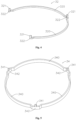
- the stator assembly further includes a first neutral connecting plate 32 extending in an arc shape, the first neutral connecting plate 32 includes an arc-shaped plate and a plurality of single-phase connecting groups, the arc-shaped plate includes a first arc-shaped portion 320 and a first external protruding portion 322, and there are two first arc-shaped portions 320 and three first external protruding portions 322, the first arc-shaped portion 320 of the arc-shaped plate is arranged in a concentric arc extension manner, the first arc-shaped portion 320 and the first external protruding portion 322 are sequentially connected at intervals, an outer diameter of the first external protruding portion 322 is greater than that of the first arc-shaped portion 320, each single-phase connecting group is arranged on each the first external protruding portion 322, each single-phase connecting group is arranged on an axial end surface of the first external protruding portion 322 based on an axial direction of the arc-shaped plate, the first external protruding portion
- a number of a first neutral connecting end 321 of each single-phase connecting group is one, the first neutral connecting end 321 is centrally arranged on an axial end surface of the plane section, the first neutral connecting end 321 extends along the axial direction of the arc-shaped plate, first neutral connecting ends 321 of the plurality of single-phase connecting groups are uniformly distributed on the arc-shaped plate along the circumferential direction, two first neutral connecting ends 321 are arranged at two ends of the arc-shaped plate, a partition portion is provided between the two ends, and the first neutral connecting ends 321, the first arc-shaped portion 320 and the first external protruding portion 322 are integrally formed.
- the first arc-shaped portion 320 extending on the inner side is configured for avoiding the welding end of the winding wire
- the first arc-shaped portion 320 of the neutral connecting plate 32 is located on the radial inner side of the winding part 31, in the axial projection of the stator core 11, a projection of the first neutral connecting plate 32 is located on a radial inner side of a projection of the first star point end 312 based on the stator core 11, a projection of the first leading-out end 311 is located on a radial inner side of the projection of the first neutral connecting plate 32 based on the stator core 11, then the first neutral connecting end 321 of the first external protruding portion 322 extends to an outer side of the second leading-out end 313 and is welded with the second star point end 314, and three first neutral connecting ends 321 of the first neutral connecting plate 32 are respectively connected to the second star point ends 314 of the U-phase, the V-phase and the W-phase, thus achieving a star connection method.
- a second neutral connecting plate 34 shown in Fig. 5 is also adopted, the second neutral connecting plate 34 in a closed ring shape includes a ring-shaped plate and a plurality of single-phase connecting groups, the ring-shaped plate is arranged in a closed ring shape, the plurality of single-phase connecting groups are uniformly distributed on the ring-shaped plate along a circumferential direction, the ring-shaped plate includes an second arc-shaped portion 340 and a second external protruding portion 342, and there are a plurality of second arc-shaped portions 340 and a plurality of second external protruding portions 342, the plurality of second arc-shaped portions 340 and the plurality of second external protruding portions 342 are connected end to end at intervals, an outer diameter of the second external protruding portion 342 is greater than that of the second arc-shaped portion 340, each single-phase connecting group is arranged on each second external protruding portion 342, the second external pro
- Each single-phase connecting group includes a second neutral connecting end 341, the second neutral connecting end 341 is arranged on the axial end surface of the plane section of the second external protruding portion 342 based on the axial direction of the ring-shaped plate, second neutral connecting ends 341 of the plurality of single-phase connecting groups are uniformly distributed along the circumferential direction and arranged at an included angle of 120°, and the second neutral connecting end 341 extends along the axial direction of the ring-shaped plate.
- Second neutral connecting ends 341, the arc-shaped portion and the external protruding portion in the ring-shaped plate are integrally formed.
- the second neutral connecting end 341 is welded with the second star point end 314, the second arc-shaped portion 340 avoids the welding end of the winding wire, the second arc-shaped portion 340 of the second neutral connecting plate 34 is located on the radial inner side of the winding part 31, and then connection of star point ends of each phase is also able to be achieved.
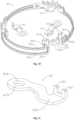
- a third neutral connecting plate 35 shown in Fig. 6 is also adopted, the split third neutral connecting plate 35 includes an arc-shaped plate 354 and a single-phase connector 352, and there are six arc-shaped plates 354 and three single-phase connectors 352, the single-phase connector 352 includes a third external protruding portion 3521 and an inner connecting portions 3522,, and there are two inner connecting portions 3522, the two inner connecting portions 3522 are located on two sides of the external protruding portion 3521, a third neutral connecting end 351 is arranged on an axial end surface of the third external protruding portion 3521 based on an axial direction of the arc-shaped plate 354, two first end connecting ends 353 are arranged on an axial end surface of one inner connecting part 3522 based on the axial direction of the arc-shaped plate 354 and are distributed along the circumferential direction, and the third external protruding portion, the two inner connecting portions, the third neutral connecting end and the two first end connecting end are
- the six arc-shaped plates 354 are arranged in a concentric arc extension manner, a second end connecting end 355 is provided at ends of the arc-shaped plate 354 and is distributed along the circumferential direction, the third neutral connecting end 351, the first end connecting end 353 and the second end connecting end 355 are arranged in an axial extension manner, the inner connecting part 3522 is located on a radial inner side of the second end connecting end 355, the first end connecting end 353 and the second end connecting end 355 are distributed along the radial direction of the arc-shaped plate 354, the first end connecting end 353 is located on an inner side of the second end connecting end 355, each first end connecting end 353 is welded with each second end connecting end 355, then two arc-shaped plates 354 are connected on the same side of the single-phase connector 352, and the two arc-shaped plates 354 on the same side are distributed along the axial direction.
- the arc-shaped plates 354 and single-phase connectors 352 are connected end to end at intervals to form the third neutral connecting plate 35 in a closed ring-shape, based on a circle center of the arc-shaped plate 354, a distance between the third neutral connecting end 351 and the circle center is greater than an outer diameter of the arc-shaped plate 354.
- the single-phase connector is also able to be connected on single side, that is, two arc-shaped plates and at least three single-phase connectors are adopted to form the neutral connecting plate in arc-shaped extension, meanwhile, an extension arc of the arc-shaped plate is also able to be adjusted, and then a connection combination manner of six single-phase connectors is formed.
- the third neutral connecting end 351 is welded with the second star point end 314, the arc-shaped plate 354 avoids the welding end of the winding wire, the arc-shaped plate 354 of the third neutral connecting plate 35 is located on the radial inner side of the winding part 31, and then connection of star point ends of each phase is also able to be achieved.
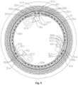
- a stator assembly includes a stator core 11 and a stator winding 3, the stator core 11 is provided with a plurality of stator slots 12, the plurality of stator slots 12 are distributed along the circumferential direction of the stator core 11, in the embodiment, the number of the plurality of stator slots is 48, the number of phases is three, the three phases include a U-phase, a V-phase, and a W-phase, each of the plurality of stator slots 12 is provided with a plurality of slot layers, the plurality of slot layers are distributed along the radial direction of the stator core 11, the plurality of slot layers are respectively an a-th layer, a b-th layer, a c-th layer, a d-th layer, an e-th layer, and a f-th layer from inside to outside along the radial direction, and the above stator parameter variations are able to be set according to specific motor application.
- the stator winding 3 includes a U-phase winding, a V-phase winding and a W-phase winding, in the embodiment, a flat wire is utilized and a wave winding manner is adopted for arrangement, the flat wire is inserted into a corresponding slot layer of a stator slot, a starting point of the winding wire is from an innermost layer to an outermost layer in a clockwise winding manner, then from the outermost layer to the innermost layer, to the tail end, from the innermost layer to the outermost layer in an anticlockwise winding manner through an adapter, then from the outermost layer to the innermost layer, after the end of each flat wire deflects, the axial two ends are welded, and finally, the star point ends of each phase are welded together through a neutral wire.
- each phase of winding is arranged in parallel in two winding wires, a first winding wire and a second winding wire of the same phase are distributed in parallel
- the U-phase is taken as an example
- the first winding wire of the U-phase and the second winding wire of the U-phase are connected in parallel
- the first leading-out end 311 of the first winding wire of the U-phase is led out from the innermost slot layer (the a-th layer) of the 1st slot
- the second leading-out end 313 of the second winding wire of the U-phase is led out from the innermost slot layer (the a-th layer) of the 48th slot
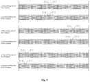
- winding arrangement is carried out according to a winding schematic diagram shown in Fig.
- a thick line in the figure is a wire inserting end
- a thin line is a welding end
- the first star point end 312 of the first winding wire of the U-phase is led out from the secondary innermost slot layer (the b-th layer) of the 43th slot
- the second star point end 314 of the second winding wire of the U-phase is led out from the secondary innermost slot layer (the b-th layer) of the 42nd slot.
- first leading-out end 311 and the first star point end 312 deflect to a position opposite the 46th slot
- the second leading-out end 313 and the second star point end 314 deflect to a position opposite the 45th slot.
- the V-phase winding and the W-phase winding are both the same as the U-phase in winding, connecting manner and leading-out manner, specifically, arrangement is able to be carried out referring to a winding schematic diagram shown in Fig. 9 , the first leading-out end 311 of the first winding wire of the V-phase is led out from the a-th layer of the 17th slot, the first star point end 312 of the first winding wire of the V-phase is led out from the b-th layer of the 11th slot, the second leading-out end 313 of the second winding wire of the V-phase is led out from the a-th layer of the 16th slot, the second star point end 314 of the second winding wire of the V-phase is led out from the b-th layer of the 10th slot, the first leading-out end 311 of the first winding wire of the W-phase is led out from the a-th layer of the 33th slot, the first star point end 312 of the first winding wire of the W-phase is led
- the first leading-out end 311, the first star point end 312, the second leading-out end 313 and the second star point end 314 of one winding wire of each phase are located on the radial inner side of the winding part 31 based on the stator core 11, leading-out ends of two winding wires of each phase are uniformly distributed along the circumferential direction of the stator core 11, star point ends of two winding wires of each phase are uniformly distributed along the circumferential direction of the stator core 11, more specifically, in the axial projection of the stator core 11, the projection of the first leading-out end 311 is located on the radial inner side of the projection of the first star point end 312 based on the stator core 11, and the projection of the second leading-out end 313 is located on the radial inner side of the projection of the second star point end 314 based on the stator core 11.
- the first leading-out end 311 of the first winding wire of the U-phase, the first leading-out end 311 of the first winding wire of the V-phase and the first leading-out end 311 of the first winding wire of the W-phase are circumferentially and uniformly distributed with an included angle of 120°
- the second leading-out end 313 of the second winding wire of the U-phase, the second leading-out end 313 of the second winding wire of the V-phase and the second leading-out end 313 of the second winding wire of the W-phase are circumferentially and uniformly distributed with an included angle of 120°
- the second star point end 314 of the first winding wire of the U-phase, the second star point end 314 of the first winding wire of the V-phase and the second star point end 314 of the first winding wire of the W-phase are circumferentially and uniformly distributed with an included angle of 120°
- the stator assembly further includes a third neutral connecting plate 35, the third neutral connecting plate 35 adopts the split neutral connecting plate as shown in Fig. 6 , each phase has two star point ends of two winding wires, therefore, in the embodiment, two third neutral connecting ends 351 are arranged on the second external protruding portion 3521 of the single-phase connector 352, the two third neutral connecting ends 351 are respectively located on two sides, the two third neutral connecting ends 351 of the third external protruding portion 3521 extends to the outer side of the second leading-out end 313 and are respectively welded with the first star point end 312 and the second star point end 314, and the six third neutral connecting ends 351 of the third neutral connecting plate 35 are respectively connected to star point ends of the U-phase, the V-phase and the W-phase, thus achieving the star connecting method.
- the third external protruding portion 3521 of the single-phase connector 352 is located between the star point end and the leading-out end of the same winding wire, the arc-shaped plate 354 avoids the welding end of the winding wire, the arc-shaped plate 354 of the third neutral connecting plate 35 is located on the radial inner side of the winding part 31.
- the stator assembly further includes a second single-phase terminal 42, and there are three second single-phase terminals 42, the three second single-phase terminals 42 are located on the radial inner side of the winding part 31 and are distributed uniformly along the circumferential direction, the second single-phase terminal 42 includes a wiring board 423 and an access board 422, two adjacent second access ends 421 are arranged on the access board 422, extension directions of the two second access ends 421 are vertical to that the access board 422, an extension direction of the access board 422 is parallel to that of the wiring board 423, after the second single-phase terminal 42 is connected to the first leading-out end 311, two second access ends 421 and the first leading-out end 311 extend in the same direction and extend along the axial direction, heights of the two second access ends 421 are the same, the wiring board 423 and the access board 422 are connected in a misaligned manner, the second access ends 421 and the wiring board 423 are located on both sides
- a wiring hole 424 is arranged in the wiring board 423 in a penetrating manner, the wiring board 423 and the wiring hole 424 are close to the arc-shaped plate 354 of the neutral connecting plate, and the wiring board 423 is located on the radial inner side of the neutral connecting plate.
- Each second access end 421 of the second single-phase terminal 42 is welded with the first leading-out end 311 and the second leading-out end 313 respectively, and the wiring holes 424 of the three second single-phase terminals 42 are respectively connected to terminals of the U, V and W phases in the motor controller correspondingly, and then power output and control are able to be achieved.
- the second single-phase terminal 42 is a first single-phase terminal 41 after one second access end 421 is saved, referring to Fig. 2 , the three first single-phase terminals 41 are located on the radial inner side of the winding part 31 and distributed uniformly along the circumferential direction, and are located on the radial inner side of the first neutral connecting plate 32, the first single-phase terminal 41 is provided with a first access end 411, the first access end 411 is connected to the first leading-out end 311, and meanwhile, the first single-phase terminal 41 is connected to the terminals of the U, V and W phases in the motor controller, then power output and control are able to be achieved.
- the second neutral connecting plate 34 shown in Fig. 5 is able to be adopted, the single-phase connecting group includes two second neutral connecting ends 341, each second neutral connecting end 341 is arranged on the axial end surface of the plane section of the second external protruding portion 342 based on the ring-shaped plate, the two second neutral connecting ends 341 are distributed on two sides, the plurality of second neutral connecting ends 341 on the same side are uniformly distributed along the circumferential direction and arranged at an included angle of 120°, and the plurality of second neutral connecting ends 341 are respectively welded with the first star point end 312 and the second star point end 314 to achieve a star connection method.
- the first neutral connecting plate 32 shown in Fig. 4 is able to be adopted, the single-phase connecting group includes two first neutral connecting ends 321, the two first neutral connecting ends 321 are arranged on the axial end surface of the first external protruding portion 322 and are distributed on two sides, the plurality of first neutral connecting ends 321 on the same side are uniformly distributed along the circumferential direction and arranged at an included angle of 120°, and the plurality of first neutral connecting ends 321 are respectively welded with the first star point end 312 and the second star point end 314 to achieve a star connection method.
- a stator assembly 511 includes a stator core 5111, a stator winding and a neutral connecting assembly 52, the stator core 5111 is provided with a plurality of stator slots 5112, the plurality of stator slots 5112 are distributed along the circumferential direction of the stator core 5111, each of the plurality of stator slots 5112 is provided with a plurality of slot layers, the plurality of slot layers are distributed along the radial direction of the stator core 5111, and the numbers of the stator slots and the slot layers and stator relevant parameters are able to set according to specific motor application.
- the stator winding includes a U-phase winding, a V-phase winding and a W-phase winding, in the embodiment, a flat wire is utilized and a wave winding manner is adopted for arrangement, the flat wire is inserted into a corresponding slot layer of a stator slot, the starting point of the winding wire is from the innermost layer to the outermost layer in a clockwise winding manner, then from the outermost layer to the innermost layer, to the tail end, from the innermost layer to the outermost layer in an anticlockwise winding manner through an adapter, then from the outermost layer to the innermost layer, after the end of each flat wire deflects, the axial two ends are welded, and finally, the star point ends of each phase are welded together through a neutral wire.
- the specific winding method refers to the stator assembly disclosed in Chinese Patent No. CN114204725A .
- the winding part 5113 of two winding wires of each phase of the stator winding is arranged in the plurality of stator slots 5112, each phase of winding is arranged in parallel in two winding wires, a first winding wire and a second winding wire of the same phase are distributed in parallel, leading-out ends 5115 of the two winding wires of each phase are all located on the radial inner side of the winding part 5113 based on the stator core 5111, the leading-out ends 5115 of the two winding wires of each phase are respectively led out from the innermost slot layers of the plurality of slot layers of two adjacent stator slots 5112 of the plurality of stator slots 5112, the leading-out ends 5115 of the first winding wire of each phase are uniformly distributed along the circumferential direction of the stator core 5111, and the leading-out ends 5115 of the second winding wires of each phase are uniformly distributed along the circumferential direction of the stator core 5111, the leading-out ends 5115 are connected to a
- Star point ends 5114 of the two winding wires of each phase are all located on the radial inner side of the winding part 5113 based on the stator core 5111, the star point ends 5114 of the two winding wires of each phase are all led out from the secondary innermost slot layers of the plurality of slot layers of two adjacent stator slots 5112 of the plurality of stator slots 5112, the star point ends 5114 of the first winding wire of each phase are uniformly distributed along the circumferential direction of the stator core 5111, and the star point ends 5114 of the second winding wire of each phase are uniformly distributed along the circumferential direction of the stator core 5111.
- Both the leading-out ends 5115 and the star point ends 5114 are led out towards the axial outer side of the stator core 5111, in the axial projection of the stator core 5111, the projection of the leading-out end 5115 is located on the radial inner side of the projection of the star point end 5114 based on the stator core 5111.
- the neural connecting assembly 52 includes a star point connecting plate 521 and an arc-shaped connecting plate 522, and there are three star point connecting plates 521 and three arc-shaped connecting plates 522, both the star point connecting plate 521 and the arc-shaped connecting plate 522 are formed by integrated stamping, a welding flat plate 5211 is provided in a middle of the star point connecting plate 521, a connecting arm 5213 is provided on each of two sides of the welding flat plate 5211, a fixing end of the connecting arm 5213 is close to the axial inner side of the stator core 5111 and is connected to the welding flat plate 5211, a first connecting end 5212 is provided at a free end of the connecting arm 5213, so that the first connecting end 5212 is respectively located on each of two sides of the welding flat plate 5211.
- the arc-shaped connecting pate 522 extends in an arc shape
- a second connecting end 5221 is provided at each of two ends of the arc-shaped connecting pate 522
- the star point connecting plate 521 and the arc-shaped connecting plate 522 are connected in sequence at intervals
- one first connecting end 5212 is welded with one second connecting end 5221
- the first connecting end 5212 and the second connecting end 5221 are located on the axial inner side of the star point ends 5114 based on the stator core 5111
- both the first connecting end 5212 and the second connecting end 5221 are led out towards the axial inner side of the stator core 5111, namely, the first connecting end 5212 and the second connecting end 5221 are led out towards the opposite direction of the star point ends 5114.
- the welding flat plate 5211 is located between the leading-out ends 5115 and the star point ends 5114, the welding flat plate is connected to two star point ends 5114 of each phase, the connecting arm 5213 extends out towards the radial inner side, so that the second connecting end 5221 is located on the radial inner side of the first connecting end 5212 based on the stator core 5111, both the second connecting end 5221 and the arc-shaped connecting plate 522 are located on the radial inner side of the winding part 5113, and thus connection of a plurality of star point ends 5114 is achieved.
- the motor includes a rotor assembly, and the stator assembly in the above embodiment, the rotor assembly is rotatably arranged in the stator core, and the rotor assembly includes a rotor and a magnet arranged on the rotor.
- the powertrain includes a motor and a motor control apparatus, the motor includes a rotor assembly and the stator assembly in the above embodiment, the motor control apparatus is able to adopt a three-phase wiring holder and a motor control apparatus disclosed in patent No. CN110912326A "Three-Phase Wiring Holder, Driving Assembly and Vehicle", the motor control apparatus is connected at the axial end of the motor, the three-phase wiring holder is arranged in the middle of the motor control apparatus, the three-phase wiring holder of the motor control apparatus is provided with at least three single-phase terminals in the middle, the at least three single-phase terminals are uniformly distributed along the circumferential direction, and the leading-out end is connected to the single-phase terminal.
- a vehicle includes the driving assembly in the above embodiment, the driving assembly is able to be integrated with or without a transmission, and the vehicle is able to be a new energy electric car, a new energy electric coach, a new energy electric truck, a new energy electric cleaning vehicle, a new energy electric rail vehicle, a new energy electric flying vehicle, a new energy electric shipping vehicles and the like.
- the star point ends are able to be uniformly arranged on the radial outer side of the winding along the circumferential direction, then the star point ends are connected through the neutral connecting plate on the outer side, the match of the leading-out end is able to be configured according to the number of phase and the number of path of the winding, the included angle between the leading-out ends is able to be 120°, 60°, 45°, 30° or other angles in uniform distribution, in addition, the neutral connecting plate is able to be arranged in a ring shape and an arc shape as a whole, namely, the convex design is not adopted, the protruding of the neutral connecting plate and connection to the star point ends are able to be utilized, in addition, the outgoing positions of the leading-out end of each phase and the star point end of each phase are uniformly distributed along the circumferential direction correspondingly, meanwhile, the leading-out end of each phase and the star point end of each phase are
- the leading-out ends are arranged on the radial inner side of the winding part and uniformly distributed along the circumferential direction, the star point ends are able to be distributed on the outer side or inner side and a star connection method or a delta connection method are able to be adopted according to requirements, then the resistance of each phase adopt be balanced, the current in each phase adopt be balanced, thus the operation stability and related performance of the motor are improved, meanwhile, the axial space and radial inner space of the motor are fully utilized, the end height and radial arrangement space of the motor winding are reduced as a whole, which is beneficial for reducing use of the volume of the motor of the stator assembly.
- leading-out ends of two winding wires connected in parallel of each phase are all located on the radial inner side of the winding part and the leading-out ends of the corresponding paths of each phase are uniformly distributed along the circumferential direction
- the star point end may be distributed on the outer side or inner side and a star connection method or a delta connection method are able to be adopted according to requirements, then the resistance of each phase is able to be balanced, the current in each phase is able to be balanced, and thus the operation stability and related performance of the motor are improved.
- the star point ends are arranged on the radial inner side of the winding part and uniformly distributed along the circumferential direction, in match with connection of the neutral connecting ends uniformly distributed in the circumferential direction and the star point ends, the resistance of each phase is able to be balanced, the current in each phase is able to be balanced, meanwhile, the single-phase connecting group is arranged on the axial end surface of the external protruding portion, the arc-shaped portion is arranged with a small outer diameter, the external protruding portion is configured for convex connection with the star point end, while the arc-shaped portion on the inner side may avoid the arrangement structure of the winding, so that the gap of each part is uniform, in addition, the space of the end of the winding is able to be saved, the neutral connecting end extending in the axial direction is in the same direction as the star point end, so that the welding connection process at the end is facilitated. Meanwhile, a partition part is available between the single-phase connecting groups on two ends, so that it is easier to process
- the misaligned arrangement saves axial space, meanwhile, two access ends are both located on the same side part in the extension direction of the wiring board, so that the space on the inner side in the radial direction is able to be saved, in match with uniform distribution in the circumferential direction and connection to the leading-out end, the resistance of each phase is able to be balanced, the current in each phase is able to be balanced, the single-phase terminal distributed on the inner side is able to avoid the arrangement structure of the winding and is also able to save the space of the end of the winding wire, the axial space and the radial inner pace of the motor are able to be fully utilized, and the end height and radial arrangement space of the motor winding are reduced as a whole, which is beneficial for reducing use of the volume of the motor of the stator
- the stator assembly, the motor, the powertrain and the vehicle of the present invention are applicable to the technical field of motors, the leading-out ends are arranged on the radial inner side of the winding part and uniformly distributed along the circumferential direction, the star point end may be distributed on the outer side or inner side and may adopt a star connection method or a delta connection method according to requirements, then the resistance of each phase is able to be balanced, the current in each phase is able to be balanced, thus the operation stability and related performance of the motor are improved, meanwhile, the axial space and radial inner space of the motor are fully utilized, the end height and radial arrangement space of the motor winding are reduced as a whole, which is beneficial for reducing use of the volume of the motor of the stator assembly.
Landscapes
- Engineering & Computer Science (AREA)
- Power Engineering (AREA)
- Transportation (AREA)
- Mechanical Engineering (AREA)
- Windings For Motors And Generators (AREA)
Applications Claiming Priority (4)
| Application Number | Priority Date | Filing Date | Title |
|---|---|---|---|
| CN202210139423.6A CN114204725B (zh) | 2022-02-16 | 2022-02-16 | 定子组件、电机、动力总成和交通工具 |
| CN202222372175.8U CN218161968U (zh) | 2022-09-05 | 2022-09-05 | 定子组件、电机、动力总成和交通工具 |
| EP22926814.9A EP4481995A4 (de) | 2022-02-16 | 2022-11-16 | Statoranordnung, elektromotor, antriebsstrang und fahrzeug |
| PCT/CN2022/132235 WO2023155510A1 (zh) | 2022-02-16 | 2022-11-16 | 定子组件、电机、动力总成和交通工具 |
Related Parent Applications (2)
| Application Number | Title | Priority Date | Filing Date |
|---|---|---|---|
| EP22926814.9A Division EP4481995A4 (de) | 2022-02-16 | 2022-11-16 | Statoranordnung, elektromotor, antriebsstrang und fahrzeug |
| EP22926814.9A Division-Into EP4481995A4 (de) | 2022-02-16 | 2022-11-16 | Statoranordnung, elektromotor, antriebsstrang und fahrzeug |
Publications (2)
| Publication Number | Publication Date |
|---|---|
| EP4485767A2 true EP4485767A2 (de) | 2025-01-01 |
| EP4485767A3 EP4485767A3 (de) | 2025-03-05 |
Family
ID=87577452
Family Applications (2)
| Application Number | Title | Priority Date | Filing Date |
|---|---|---|---|
| EP24208993.6A Withdrawn EP4485767A3 (de) | 2022-02-16 | 2022-11-16 | Statoranordnung, motor, antriebsstrang und fahrzeug |
| EP22926814.9A Pending EP4481995A4 (de) | 2022-02-16 | 2022-11-16 | Statoranordnung, elektromotor, antriebsstrang und fahrzeug |
Family Applications After (1)
| Application Number | Title | Priority Date | Filing Date |
|---|---|---|---|
| EP22926814.9A Pending EP4481995A4 (de) | 2022-02-16 | 2022-11-16 | Statoranordnung, elektromotor, antriebsstrang und fahrzeug |
Country Status (5)
| Country | Link |
|---|---|
| US (2) | US20250167619A1 (de) |
| EP (2) | EP4485767A3 (de) |
| JP (1) | JP2025505283A (de) |
| KR (1) | KR102872589B1 (de) |
| WO (1) | WO2023155510A1 (de) |
Families Citing this family (1)
| Publication number | Priority date | Publication date | Assignee | Title |
|---|---|---|---|---|
| JP2025187068A (ja) * | 2024-06-13 | 2025-12-25 | 株式会社東芝 | 固定子および回転電機 |
Citations (2)
| Publication number | Priority date | Publication date | Assignee | Title |
|---|---|---|---|---|
| CN110912326A (zh) | 2019-12-06 | 2020-03-24 | 珠海英搏尔电气股份有限公司 | 三相接线座、驱动总成和交通工具 |
| CN114204725A (zh) | 2022-02-16 | 2022-03-18 | 珠海英搏尔电气股份有限公司 | 定子组件、电机、动力总成和交通工具 |
Family Cites Families (15)
| Publication number | Priority date | Publication date | Assignee | Title |
|---|---|---|---|---|
| JP2002084723A (ja) * | 2000-09-01 | 2002-03-22 | Mitsubishi Electric Corp | 車両用交流発電機 |
| JP2004297881A (ja) * | 2003-03-26 | 2004-10-21 | Nissan Motor Co Ltd | 電動機駆動システム |
| JP2011182512A (ja) * | 2010-02-26 | 2011-09-15 | Nsk Ltd | バスバーユニット及びこれを備えた回転電機 |
| JP2012231573A (ja) * | 2011-04-25 | 2012-11-22 | Piolax Inc | 配電用部材および配電用部材の製造方法 |
| JP5452570B2 (ja) * | 2011-11-09 | 2014-03-26 | 三菱電機株式会社 | 回転電機およびそのステータコイルの結線ユニットの製造方法 |
| JP2015061410A (ja) * | 2013-09-19 | 2015-03-30 | 株式会社デンソー | 回転電機の固定子 |
| JP6290731B2 (ja) * | 2014-07-01 | 2018-03-07 | トヨタ自動車株式会社 | 回転電機ステータ |
| JP6652811B2 (ja) * | 2015-10-27 | 2020-02-26 | 株式会社ミツバ | モータ |
| JP6623961B2 (ja) * | 2016-07-15 | 2019-12-25 | 株式会社デンソー | 回転電機の固定子 |
| CN109586464B (zh) * | 2017-09-29 | 2021-11-12 | 比亚迪股份有限公司 | 定子组件、电机和车辆 |
| CN114450870A (zh) * | 2019-09-23 | 2022-05-06 | 卡诺科技公司 | 包括具有矩形横截面的线圈元件的分数槽电动马达 |
| CN111564921A (zh) | 2020-06-10 | 2020-08-21 | 天津市松正电动汽车技术股份有限公司 | 一种电机定子及电机 |
| JP7484467B2 (ja) * | 2020-06-12 | 2024-05-16 | 株式会社デンソー | 回転電機 |
| CN111668960B (zh) * | 2020-07-07 | 2025-05-09 | 浙江龙芯电驱动科技有限公司 | 一种等高度引出式3支路叠绕定子组件及电机 |
| CN215646428U (zh) | 2021-05-14 | 2022-01-25 | 安徽威灵汽车部件有限公司 | 汇流组件、电机、电动助力转向系统和车辆 |
-
2022
- 2022-11-16 EP EP24208993.6A patent/EP4485767A3/de not_active Withdrawn
- 2022-11-16 KR KR1020247030952A patent/KR102872589B1/ko active Active
- 2022-11-16 US US18/839,413 patent/US20250167619A1/en active Pending
- 2022-11-16 JP JP2024547891A patent/JP2025505283A/ja active Pending
- 2022-11-16 EP EP22926814.9A patent/EP4481995A4/de active Pending
- 2022-11-16 WO PCT/CN2022/132235 patent/WO2023155510A1/zh not_active Ceased
-
2024
- 2024-09-17 US US18/888,050 patent/US20250015659A1/en active Pending
Patent Citations (2)
| Publication number | Priority date | Publication date | Assignee | Title |
|---|---|---|---|---|
| CN110912326A (zh) | 2019-12-06 | 2020-03-24 | 珠海英搏尔电气股份有限公司 | 三相接线座、驱动总成和交通工具 |
| CN114204725A (zh) | 2022-02-16 | 2022-03-18 | 珠海英搏尔电气股份有限公司 | 定子组件、电机、动力总成和交通工具 |
Also Published As
| Publication number | Publication date |
|---|---|
| KR20240145036A (ko) | 2024-10-04 |
| WO2023155510A1 (zh) | 2023-08-24 |
| EP4481995A4 (de) | 2026-02-11 |
| KR102872589B1 (ko) | 2025-10-17 |
| US20250015659A1 (en) | 2025-01-09 |
| EP4485767A3 (de) | 2025-03-05 |
| EP4481995A1 (de) | 2024-12-25 |
| JP2025505283A (ja) | 2025-02-21 |
| US20250167619A1 (en) | 2025-05-22 |
Similar Documents
| Publication | Publication Date | Title |
|---|---|---|
| TWI815630B (zh) | 定子、扁線電機、動力總成和車輛 | |
| JP6686103B2 (ja) | 回転電機の固定子、回転電機、および、その回転電機を備えた車両 | |
| CN111446797B (zh) | 扁线连续波绕组、定子及电机 | |
| CN113422453B (zh) | 一种六相扁线波绕组结构、六相电机、动力总成和车辆 | |
| CN108432097A (zh) | 旋转电机及车辆 | |
| US20250015659A1 (en) | Stator Assembly, Motor and Powertrain | |
| US12301083B2 (en) | Motor, and stator and electric device thereof | |
| JP3251626U (ja) | ステータ、フラットワイヤーモータ、パワートレーン及び車両 | |
| EP4407844B1 (de) | Flachdraht-elektromotor und stator dafür | |
| CN114142646A (zh) | 定子 | |
| US20150061433A1 (en) | Electricity collection and distribution ring | |
| CN114204725B (zh) | 定子组件、电机、动力总成和交通工具 | |
| CN210985775U (zh) | 电机扁铜线电枢绕组母排 | |
| CN222395511U (zh) | 电机绕组插接于电路板的电机、动力总成及电动车辆 | |
| CN208691073U (zh) | 一种电机汇流排单元、轮毂电机及机动车 | |
| CN213637234U (zh) | 一种电机定子及电机 | |
| CN218940809U (zh) | 一种电机、动力总成及车辆 | |
| CN212435461U (zh) | 一种短节距电机定子 | |
| CN117498585A (zh) | 定子组件、电机和车辆 | |
| CN117356016A (zh) | 旋转电机和电动驱动系统 | |
| CN114337033A (zh) | 一种三相扁线波绕组结构、三相电机、动力总成和车辆 | |
| CN112260426A (zh) | 一种电机定子及电机 | |
| CN221531119U (zh) | 定子结构、电机及用电设备 | |
| CN223639056U (zh) | 一种扁线电机母线排组件 | |
| CN216819545U (zh) | 一种扁线电机定子及扁线电机 |
Legal Events
| Date | Code | Title | Description |
|---|---|---|---|
| PUAI | Public reference made under article 153(3) epc to a published international application that has entered the european phase |
Free format text: ORIGINAL CODE: 0009012 |
|
| STAA | Information on the status of an ep patent application or granted ep patent |
Free format text: STATUS: REQUEST FOR EXAMINATION WAS MADE |
|
| 17P | Request for examination filed |
Effective date: 20241029 |
|
| AC | Divisional application: reference to earlier application |
Ref document number: 4481995 Country of ref document: EP Kind code of ref document: P |
|
| AK | Designated contracting states |
Kind code of ref document: A2 Designated state(s): AL AT BE BG CH CY CZ DE DK EE ES FI FR GB GR HR HU IE IS IT LI LT LU LV MC ME MK MT NL NO PL PT RO RS SE SI SK SM TR |
|
| REG | Reference to a national code |
Ref country code: DE Ref legal event code: R079 Free format text: PREVIOUS MAIN CLASS: H02K0011300000 Ipc: H02K0003500000 |
|
| PUAL | Search report despatched |
Free format text: ORIGINAL CODE: 0009013 |
|
| AK | Designated contracting states |
Kind code of ref document: A3 Designated state(s): AL AT BE BG CH CY CZ DE DK EE ES FI FR GB GR HR HU IE IS IT LI LT LU LV MC ME MK MT NL NO PL PT RO RS SE SI SK SM TR |
|
| RIC1 | Information provided on ipc code assigned before grant |
Ipc: H02K 3/28 20060101ALI20250128BHEP Ipc: H02K 3/12 20060101ALI20250128BHEP Ipc: H02K 3/50 20060101AFI20250128BHEP |
|
| GRAP | Despatch of communication of intention to grant a patent |
Free format text: ORIGINAL CODE: EPIDOSNIGR1 |
|
| STAA | Information on the status of an ep patent application or granted ep patent |
Free format text: STATUS: GRANT OF PATENT IS INTENDED |
|
| INTG | Intention to grant announced |
Effective date: 20250513 |
|
| STAA | Information on the status of an ep patent application or granted ep patent |
Free format text: STATUS: THE APPLICATION IS DEEMED TO BE WITHDRAWN |
|
| 18D | Application deemed to be withdrawn |
Effective date: 20250916 |