EP4485656A1 - Blutzuckermessgerät - Google Patents
Blutzuckermessgerät Download PDFInfo
- Publication number
- EP4485656A1 EP4485656A1 EP23759893.3A EP23759893A EP4485656A1 EP 4485656 A1 EP4485656 A1 EP 4485656A1 EP 23759893 A EP23759893 A EP 23759893A EP 4485656 A1 EP4485656 A1 EP 4485656A1
- Authority
- EP
- European Patent Office
- Prior art keywords
- main body
- body part
- battery cover
- blood glucose
- opening
- Prior art date
- Legal status (The legal status is an assumption and is not a legal conclusion. Google has not performed a legal analysis and makes no representation as to the accuracy of the status listed.)
- Pending
Links
Images


Classifications
-
- A—HUMAN NECESSITIES
- A61—MEDICAL OR VETERINARY SCIENCE; HYGIENE
- A61B—DIAGNOSIS; SURGERY; IDENTIFICATION
- A61B5/00—Measuring for diagnostic purposes; Identification of persons
- A61B5/145—Measuring characteristics of blood in vivo, e.g. gas concentration or pH-value ; Measuring characteristics of body fluids or tissues, e.g. interstitial fluid or cerebral tissue
- A61B5/14532—Measuring characteristics of blood in vivo, e.g. gas concentration or pH-value ; Measuring characteristics of body fluids or tissues, e.g. interstitial fluid or cerebral tissue for measuring glucose, e.g. by tissue impedance measurement
-
- H—ELECTRICITY
- H01—ELECTRIC ELEMENTS
- H01M—PROCESSES OR MEANS, e.g. BATTERIES, FOR THE DIRECT CONVERSION OF CHEMICAL ENERGY INTO ELECTRICAL ENERGY
- H01M50/00—Constructional details or processes of manufacture of the non-active parts of electrochemical cells other than fuel cells, e.g. hybrid cells
- H01M50/20—Mountings; Secondary casings or frames; Racks, modules or packs; Suspension devices; Shock absorbers; Transport or carrying devices; Holders
- H01M50/247—Mountings; Secondary casings or frames; Racks, modules or packs; Suspension devices; Shock absorbers; Transport or carrying devices; Holders specially adapted for portable devices, e.g. mobile phones, computers, hand tools or pacemakers
-
- H—ELECTRICITY
- H01—ELECTRIC ELEMENTS
- H01M—PROCESSES OR MEANS, e.g. BATTERIES, FOR THE DIRECT CONVERSION OF CHEMICAL ENERGY INTO ELECTRICAL ENERGY
- H01M50/00—Constructional details or processes of manufacture of the non-active parts of electrochemical cells other than fuel cells, e.g. hybrid cells
- H01M50/20—Mountings; Secondary casings or frames; Racks, modules or packs; Suspension devices; Shock absorbers; Transport or carrying devices; Holders
- H01M50/271—Lids or covers for the racks or secondary casings
-
- A—HUMAN NECESSITIES
- A61—MEDICAL OR VETERINARY SCIENCE; HYGIENE
- A61B—DIAGNOSIS; SURGERY; IDENTIFICATION
- A61B2560/00—Constructional details of operational features of apparatus; Accessories for medical measuring apparatus
- A61B2560/02—Operational features
- A61B2560/0204—Operational features of power management
- A61B2560/0214—Operational features of power management of power generation or supply
-
- A—HUMAN NECESSITIES
- A61—MEDICAL OR VETERINARY SCIENCE; HYGIENE
- A61B—DIAGNOSIS; SURGERY; IDENTIFICATION
- A61B2560/00—Constructional details of operational features of apparatus; Accessories for medical measuring apparatus
- A61B2560/04—Constructional details of apparatus
-
- A—HUMAN NECESSITIES
- A61—MEDICAL OR VETERINARY SCIENCE; HYGIENE
- A61B—DIAGNOSIS; SURGERY; IDENTIFICATION
- A61B2560/00—Constructional details of operational features of apparatus; Accessories for medical measuring apparatus
- A61B2560/04—Constructional details of apparatus
- A61B2560/0431—Portable apparatus, e.g. comprising a handle or case
-
- A—HUMAN NECESSITIES
- A61—MEDICAL OR VETERINARY SCIENCE; HYGIENE
- A61B—DIAGNOSIS; SURGERY; IDENTIFICATION
- A61B2560/00—Constructional details of operational features of apparatus; Accessories for medical measuring apparatus
- A61B2560/04—Constructional details of apparatus
- A61B2560/0462—Apparatus with built-in sensors
-
- Y—GENERAL TAGGING OF NEW TECHNOLOGICAL DEVELOPMENTS; GENERAL TAGGING OF CROSS-SECTIONAL TECHNOLOGIES SPANNING OVER SEVERAL SECTIONS OF THE IPC; TECHNICAL SUBJECTS COVERED BY FORMER USPC CROSS-REFERENCE ART COLLECTIONS [XRACs] AND DIGESTS
- Y02—TECHNOLOGIES OR APPLICATIONS FOR MITIGATION OR ADAPTATION AGAINST CLIMATE CHANGE
- Y02E—REDUCTION OF GREENHOUSE GAS [GHG] EMISSIONS, RELATED TO ENERGY GENERATION, TRANSMISSION OR DISTRIBUTION
- Y02E60/00—Enabling technologies; Technologies with a potential or indirect contribution to GHG emissions mitigation
- Y02E60/10—Energy storage using batteries
Definitions
- the present invention relates to a blood glucose meter that measures blood glucose levels.
- Conventional blood glucose meters generally use a small, replaceable battery, such as a button battery.
- the battery cover When the battery is to be replaced, the battery cover is removed from the main body part, and a new battery is installed in the battery compartment provided to the main body part.
- buttons batteries or other such small batteries are sometimes used for this purpose, in view of the risk of accidental swallowing by children, it is preferable for the structure to be such that the battery cannot be easily removed.
- Patent Literature 1 discloses a portable device equipped with a battery that is aesthetically pleasing and that allows the battery cover to be easily opened by smoothly releasing the locked state.
- Patent Literature 1 JP-A 2008-258004
- the blood glucose meter comprises a main body part, a sensor mounting part, a measurement unit, a battery compartment, a battery cover, an elastic deformation part, a lock portion, and a slide part.
- the sensor mounting part is provided to the main body part, and a blood glucose level measurement sensor is mounted thereon.
- the measurement unit measures blood deposited on the blood glucose value measurement sensor mounted on the sensor mounting part.
- the battery compartment holds a battery that supplies power to the measurement unit.
- the battery cover is removably attached to the main body part so as to cover the battery compartment, and has an opening into which a jig is inserted during removal from the main body part.
- the elastic deformation part is provided at a position opposite the battery cover in the main body part and deforms when pressed by the jig inserted through the opening.
- the lock portion is provided at a position exposed to the outside from the opening, is molded integrally with the elastic deformation part, and unlatches the battery cover from the main body part when pressed by the jig.
- the slide part is provided to the main body part and slides so as to guide the battery cover in the removal direction when the lock portion is unlatched from the main body part.
- a blood glucose meter that measures blood glucose level in a state in which a blood glucose level measurement sensor on which the blood of a diabetic patient or the like is deposited has been mounted, and that is powered by a battery held in a battery compartment of a main body part
- a jig is inserted into the opening of the battery cover to deform the elastic deformation part and release the latching by the lock portion, allowing the battery cover to be slid to its open state, and if an attempt is made to forcibly slide the battery cover while latched by the lock portion, a force is exerted on the elastic deformation part in the compression direction.
- the battery cover is forcibly slid while still latched to the main body part by the lock portion, a force will be exerted on the elastic deformation part in the compression direction, making it less likely that the elastic deformation part will be damaged.
- the blood glucose meter according to the second invention is the blood glucose meter according to the first invention, further comprising a capillary flow path that is provided so as to surround at least part of the opening in the battery cover, and that guides liquid that has entered through the opening by capillary action to the outside of the main body part.
- liquid such as blood or alcohol clinging near the opening will be guided in the desired direction (to outside the main body part) along the capillary flow path by capillary action. This prevents liquid from entering the battery compartment through the opening.
- the blood glucose meter according to the third invention is the blood glucose meter according to the second invention, wherein the capillary flow path is formed as a groove provided between a plurality of ribs provided around the opening.
- the plurality of ribs provided so as to surround at least a portion of the outer periphery of the opening form capillary flow paths in between the ribs. Therefore, it is possible to prevent liquid adhering to the vicinity of the opening from infiltrating into the battery compartment.
- the blood glucose meter according to the fourth invention is the blood glucose meter according to the second or third invention, wherein the capillary flow path is provided on the rear surface side of the battery cover.
- the blood glucose meter according to the fifth invention is the blood glucose meter according to any of the second to fourth inventions, further comprising a liquid guiding flow path that is provided to the main body part and guides the liquid that has come in through the opening to the outside of the main body part.
- the liquid guided in the desired direction by the capillary flow path provided to the battery cover can be guided to the outside of the main body part by the liquid guiding flow path provided on the main body part side. This avoid problems caused when liquid that has come in through the opening moves into the battery compartment.
- the blood glucose meter according to the sixth invention of the invention is the blood glucose meter according to the fifth invention, wherein the liquid guiding flow path is provided to the main body part at a position opposite the capillary flow path.
- the liquid that has been guided by the capillary flow path provided on the battery cover side moves to the liquid guiding flow path provided to the main body part at a position opposite the capillary flow path, and is moved by the liquid guiding flow path to outside the main body part. This prevent problems attributable to liquid that has come into the main body part through the opening in the battery cover.
- the blood glucose meter according to the seventh invention of the present invention is the blood glucose meter according to any of the first to sixth inventions, further comprising a latching hole that is provided to the main body part and is formed along the sliding direction of the battery cover, and a latched part that is provided to the battery cover and is inserted into the latching hole and restricts movement in a direction intersecting the sliding direction when the battery cover is attached to the main body part.
- the battery cover when the battery cover is attached to the main body part, the battery cover is prevented from lifting up in the direction intersecting the sliding direction by the latched state between the latching hole and the latched part, and this maintains the locked.
- the blood glucose meter according to the eighth invention is the blood glucose meter according to any of the first to seventh inventions, wherein the lock portion is formed such that the end that is farther from the center of deformation when the jig is inserted into the opening and the elastic deformation part is deformed is higher than the end that is closer to the center of deformation.
- the blood glucose meter according to the ninth invention is the blood glucose meter according to any of the first to eighth inventions, wherein the elastic deformation part has a reinforcing rib that is provided at a position close to the lock portion and has a thicker wall than a position farther away from the lock portion.
- the blood glucose meter according to the tenth invention is the blood glucose meter according to any of the first to ninth inventions, wherein the lock portion is provided at a position farther to the inside than the outer contour of the main body part, through the opening.
- the lock portion which is located deeper than the outer part of the main body part, is less likely to be touched accidentally, which prevents the battery cover from being accidentally unlocked from the main part.
- the blood glucose meter according to the eleventh invention is the blood glucose meter according to any of the first to tenth inventions, wherein the opening has a chamfered portion whose diameter increases, at the upper end in the insertion direction of the jig.
- the chamfered portion forms a circular shape with a larger diameter at the end on the insertion side, so any rod-shaped member with a pointed tip can be easily used as a jig.
- the blood glucose meter according to the twelfth invention is the blood glucose meter according to any of the first to eleventh inventions, wherein the opening has a diameter smaller than the size of a child's finger.
- the blood glucose meter according to the thirteenth invention is the blood glucose meter according to the first or second invention, wherein the elastic deformation part has a recess formed so as to avoid the position of a screw attached to the main body part.
- the elastic deformation part does not end up covering the position of the screw, so the screw can be easily threaded into the screw hole.
- the blood glucose meter according to the fourteenth invention is the blood glucose meter according to the first or second invention, wherein the main body part has a latching prong that protrudes from an outer peripheral side of the battery compartment and holds the battery housed in the battery compartment.
- the battery is effectively prevented from falling out of the battery compartment when the battery cover has been removed.
- the blood glucose meter according to the fifteenth invention is the blood glucose meter according to the first or second invention, wherein the elastic deformation part is fixed to the main body part at a plurality of positions that are away from the lock portion.
- the blood glucose meter of the present invention it is possible to provide a blood glucose meter that is equipped with a locking mechanism that is resistant to damage, while preventing a child from easily removing the battery cover, for example.
- the blood glucose meter 10 according to an embodiment of the present invention will now be described through reference to Figs. 1 to 16 .
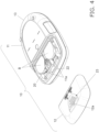
- the blood glucose meter 10 is used at home, in hospitals and other such facilities, etc., and measures the blood glucose value (glucose concentration in blood) in a state in which a sensor for measuring blood glucose level, on which the blood of a diabetic patient or other such measurement subject has been deposited, has been inserted into a sensor mounting part 13 provided at the end of a main body part 11.
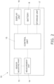
- the blood glucose meter 10 comprises the main body part 11, a battery cover 12, the sensor mounting part 13, a measurement unit 14, a control unit 15, a display unit 16, button batteries (batteries) B, a storage unit 17, and a locking mechanism 20.
- the display unit 16 and so forth are provided on the front side, a battery cover 12 is removably attached to the back side, and the measurement unit 14, the control unit 15, the button batteries (batteries) B, the storage unit, and so forth are provided on the inside.
- the battery cover 12 is removably attached to the main body part 11 so as to cover a battery compartment 11a (see Fig. 4 , etc.) on the main body part 11 side, and when the battery cover 12 is to be removed from the main body part 11, a jig Z (see Fig. (a), etc.) is inserted into the opening 12a.
- the sensor mounting part 13 is provided on the end surface of the main body part 11 shown in Fig. 1 , and a blood glucose level measurement sensor (not shown) is inserted therein.
- the sensor mounting part 13 is connected to the measurement unit 14 and is electrically connected to the electrodes of the blood glucose level measurement sensor.
- the measurement unit 14 is connected to the control unit 15 and the sensor mounting part 13, and measures the glucose concentration in blood by means of an electrical signal received via the sensor mounting part 13.
- the blood glucose level in the blood is measured by the measurement unit 14.
- control unit 15 is connected to the measurement unit 14, the display unit 16, the button batteries (batteries) B, and the storage unit 17.
- the control unit 15 reads various kinds of information (data) stored in the storage unit 17 and executes various kinds of processing using the blood glucose value data measured by the measurement unit 14.
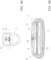
- the display unit 16 is disposed on the surface on the opposite side from the main body part 11 as shown in Fig. 1 , and performs various displays. As shown in Fig. 2 , the display unit 16 is connected to the control unit 15, and displays the measurement results from the measurement unit 14, the analysis results based on these measurement results, the current time, and the like.
- the button batteries B are connected to the control unit 15, and are installed in the battery compartment 11a (see Fig. 4 , etc.) provided to the main body part 11 as a power source for driving the measurement unit 14, the display unit 16, etc.
- the storage unit 17 is connected to the control unit 15 and stores various kinds of information (data), such as blood glucose value data measured by the measurement unit 14, information about the time of measurement, and analysis results based on the measurement results.
- a nonvolatile memory such as an EEPROM (electrically erasable programmable read-only memory) can be used as the storage unit 17.
- EEPROM electrically erasable programmable read-only memory
- the locking mechanism 20 is made up of a hinge 21 and a latching hole 22 provided on the main body part 11 side, and an opening 12a and a latched portion 12b provided on the battery cover 12 side.
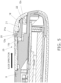
- the hinge 21 is elastically deformed when the jig Z is inserted into the opening 12a of the battery cover 12 and pressed downward, which causes part of the hinge 21 (a lock pin 21a; see Fig. 5 , etc.) latched in the opening 12a to come out of the opening 12a and releases the locked state.
- the lock pin 21a is a substantially cylindrical portion integrally formed so as to protrude upward in the drawing at one end of the hinge 21, and in the locked state, restricts the movement of the battery cover 12 in the sliding direction in a state of being inserted in the opening 12a of the battery cover 12.
- the latching hole 22 is a hole made in the end surface of the main body part 11, and is formed along the sliding direction of the battery cover 12.
- the opening 12a is a through-hole formed in the approximate center in the width direction of the battery cover 12, and in the locked state, the lock pin 21a is latched, and when transitioning to an unlocked state, the jig Z is inserted as shown in Fig. 3A .
- the opening 12a has a C surface (chamfered portion) 12aa (see Figs. 6A and 6B , etc.) whose diameter increases upward when viewed in the insertion direction of the jig Z.
- the opening 12a has a diameter whose smallest inside diameter is less than the size of a child's finger.
- the latched portion 12b is provided on the inner surface side of the battery cover 12 and is formed so as to protrude in the sliding direction of the battery cover 12. When the battery cover 12 is in its locked state, the latched portion 12b is held in a state of being inserted into the latching hole 22, as shown in Fig. 5 .
- the jig Z with a pointed tip is inserted into the opening 12a and pressed as shown in Fig. 3A in order to remove the battery cover provided on the back side of the main body part 11.
- the user places a finger on the finger pad 23, which includes a depression on the surface of the battery cover 12 and three ribs of varying length, and slides the battery cover 12 in the direction of the arrow in the drawing, which releases the locking of the battery cover 12 by the locking mechanism 20.
- the battery cover 12 can be removed from the main body part 11 and the button batteries B can be installed in the battery compartment 11a of the main body part 11, or can be replaced with new button batteries B.
- the battery cover 12 is unlocked by the locking mechanism 20 provided near the battery compartment 11a of the main body part 11, and is removed from the main body part 11.
- the substantially cylindrical lock pin 21a provided on the first end side of the hinge (elastic deformation part) 21 is inserted into an opening 12a of the battery cover 12 and held in that state, thus rendering the battery cover 12 immovable in the sliding direction.
- the hinge 21 is in a steady state without being elastically deformed, and the lock pin 21a provided at the tip of the hinge 21 is latched in the opening 12a of the battery cover 12.
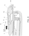
- the opening 12a in the battery cover 12 presses the lock pin 21a of the hinge 21 to the right in Fig. 6A . Accordingly, movement of the locked battery cover 12 is restricted, and even though a force that attempts to open the battery cover 12 is transmitted to the hinge 21, this force is applied to the hinge 21 in the compression direction. Consequently, the hinge 21 is less likely to be damaged when there is an attempt to forcibly open the battery cover 12.
- the hinge 21 is held in contact with a flat receiving portion (breakage prevention portion) 11b provided to the main body part 11, as shown in Fig. 6B , in order to prevent it breakage caused by excessive force when pressed on by the jig Z and elastically deformed.
- the hinge 21 will be held by the receiving portion 11b at the position immediately after that when the lock pin 21a was removed from the opening 12a. Therefore, this prevents the hinge 21 from being broken.
- the lock pin 21a of the locking mechanism 20 is exposed from the opening 12a, as shown in Fig. 7A .
- the battery cover 12 is slid relative to the main body part 11 on both sides in the width direction, as shown in Figs. 9a and 9b .
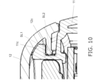
- Fig. 10 is a detail view of the X portion in Fig. 9B , including the configuration on both sides in the width direction where the battery cover 12 slides with respect to the main body part 11.
- prongs 12c provided on both sides in the width direction are guided in the sliding direction by protrusions 11c provided on the main body part 11 side at positions opposite the prongs 12c.
- the prongs 12c and the protrusions 11c slide while in contact with each other over a sliding surface (slide section) SL1 running in the substantially horizontal direction and a sliding surface (slide section) SL2 running in the substantially vertical direction.
- the battery cover 12 moves in the sliding direction in a state in which movement in the lateral direction (width direction) and up and down direction (vertical direction) is restricted by the two sliding surfaces SL1 and SL2.
- the protrusions 11c are provided over a specific length in the sliding direction. Consequently, when the prongs 12c of the battery cover 12 (see Fig. 13B ) move in the sliding direction by the length of the protrusions 11c, latching in the up and down direction (vertical direction) is released and the main body part 11 is removed.
- the lock pin 21a constituting the locking mechanism 20 is such that the first end 21aa on the side farther from the deformation center C1 of the hinge 21 in a side cross-sectional view along the lengthwise direction of the hinge 21, is higher than the second end 21ab of the hinge 21 on the side closer to the deformation center C1.
- the height of the end (first end 21aa) of the lock pin 21a located farther from the center of deformation is greater than that of the end (second end 21ab) on the opposite side (closer side), and as shown in Fig. 12 , the upper surface of the lock pin 21a is inclined. Therefore, the battery cover 12 can be easily removed while ensuring a large amount of engaging allowance of the lock pin 21a with respect to the inner peripheral surface of the opening 12a of the battery cover 12 (see Fig. 12 ).
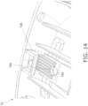
- the hinge 21 has a reinforcing rib 21b that is thicker at a position close to the lock pin 21a than at a position farther away from the lock pin 21a.
- the reinforcing rib 21b is formed from near the base of the lock pin 21a to just before the deformation center C1 so that the thickness is greater than that of the deformation center C1 of the hinge 21 (see Fig. 15 ).
- the blood glucose meter 10 in this embodiment As discussed above, the opening 12a is provided to the battery cover 12, so there is the risk that blood, alcohol, water, or another such liquid will pass through the opening 12a and make its way into the interior of the main body part 11, causing the blood glucose meter 10 to malfunction.
- the blood glucose meter 10 of this embodiment comprises a liquid intrusion prevention structure that guides any liquid coming through the opening 12a into the inside to the outside of the main body part 11.
- the battery cover 12 has a rib group (capillary flow path) 12d made up of a plurality of ribs on its back side.
- the rib group 12d is formed by disposing a plurality of ribs so as to surround a semicircular portion of the opening 12a of the battery cover 12, and a capillary flow path is formed between these ribs.
- the capillary flow path is provided so as to surround part of the opening 12a in the battery cover 12, and guides liquid that has come in through the opening 12a to the outside of the main body part 11 by capillary action.
- liquid guiding flow paths 24A and 24B are provided running around the periphery of the lock pin 21a inserted into the opening 12a.
- the liquid guiding flow paths 24A and 24B are provided around the lock pin 21a in the main body part 11, between the battery compartment 11a and the lock pin 21a, and divide in two at a position opposite the capillary flow path (rib group 12d) in the main body part 11.
- the liquid guiding flow paths 24A and 24B have grooves, making it easier to guide the liquid in the direction in which the battery cover 12 is removed (outward), which prevents the infiltration of liquid into the inside of the battery compartment 1 1a of the main body part 11. As shown in Fig.
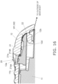
- liquid guide paths W1 and W2 indicated by dotted-line arrows guide to the outside of the main body part 11 any liquid that has moved from the opening 12a to the right side in the drawing by means of the capillary flow path (rib group 12d) formed on the back side of the battery cover 12.
- the liquid that has been guided in the desired direction by the capillary flow path (rib group 12d) provided to the battery cover 12 and by the liquid guiding flow paths 24A and 24B provided to the main body part 11 is guided to the outside of the main body part 11 along the liquid guide paths W1 and W2 while following along the main body part 11 and the battery cover 12. This prevents the liquid that has come in through the opening 12a of the battery cover 12 from moving to the battery compartment 11a in the main body part 11 and causing problems.
- the liquid guiding flow paths 24A and 24B may be formed as minute gaps so that capillary action acts on the liquid, similarly to the capillary flow paths (rib group 12d).
- the liquid that has moved to the liquid guiding flow paths 24A and 24B can be effectively moved to the outside of the main body part 11 by capillary action.
- the positional relation between the capillary flow path (rib group) 12d of the battery cover 12 and the liquid guiding flow paths (grooves) 24A and 24B of the main body part 11 may be such that these components only partially face each other, or such that they do not face each other at all, so long as the configuration prevents the liquid from coming into the battery compartment 11a.
- the configuration here is such that the liquid guiding flow paths 24A and 24B provided to the main body part 11 are divided in two near the middle between the two button batteries B, but the grooves may be divided into three or more parts, or may not be divided at all, so long as the configuration prevents liquid from coming into the battery compartment 11a.
- liquid guide paths W1 and W2 are provided only on the upper side of the hinge 21, as shown in Figs. 15 and 16 , but they may also be provided on the lower side of the hinge 21.
- the blood glucose meter 10 of this embodiment comprises the main body part 11, the sensor mounting part 13, the measurement unit 14, the battery compartment 11a, the battery cover 12, the hinge 21, the lock pin 21a, and the sliding surfaces SL1 and SL2.
- the sensor mounting part 13 is provided to the main body part 11, and a blood glucose level measurement sensor is mounted thereon.
- the measurement unit 14 measures blood deposited on the blood glucose level measurement sensor mounted in the sensor mounting part 13.
- the battery compartment 11a holds button batteries B that supply power to the measurement unit 14.
- the battery cover 12 is removably attached to the main body part 11 so as to cover the battery compartment 11a, and has the opening 12a into which the jig Z is inserted during removal from the main body part 11.
- the hinge 21 is provided at a position opposite the battery cover 12 in the main body part 11, and is deformed by being pressed by the jig Z inserted through the opening 12a.
- the lock pin 21a is provided at a position exposed to the outside through the opening 12a, and is molded integrally with the hinge 21, and when the lock pin 21a is pressed by the jig Z, the battery cover 12 is unlatched from the main body part 11.
- the sliding surfaces SL1 and SL2 are provided to the main body part 11, and when the latching of the lock pin 21a to the main body part 11 is released, these surfaces are slid so as to guide the battery cover 12 in the direction of removal. When the battery cover 12 is slid while still latched to the main body part 11 by the lock pin 21a, a compressive force is exerted on the hinge 21.
- a blood glucose meter 10 with which the hinge 21 is less likely to be damaged, while a child is prevented from easily taking off the battery cover 12, for example, can be provided.
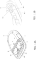
- the blood glucose meter 110 in this embodiment comprises a main body part 111, a battery cover 112, a sensor mounting part 113, and a locking mechanism 120.
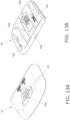
- the main body part 111 has the battery cover 112 removably attached to its back side, and is provided with the measurement unit 14, the control unit 15, the button batteries (batteries) B, the storage unit 17, etc., on its inside.
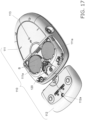
- the main body part 111 has a battery compartment 111a into which button batteries B are installed, guide grooves 111b and 111c, and latching prongs 111d.
- the battery compartment 111a is electrically connected to the control unit 15, and button batteries B are installed as a power source for driving the measurement unit 14, the display unit 16, and so on. Also, the battery compartment 111a has the latching prongs 111d (see Fig. 18 , etc.) for preventing the installed button batteries B from falling out.
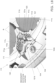
- the guide grooves 111b and 111c are grooves that guide to the outside any liquid that has come into the main body part 111 through the opening 112a in the battery cover 112, and are provided around the locking mechanism 120 as shown in Fig. 18 .
- the guide groove 11 1b is a substantially U-shaped groove provided near the lock pin 121a of the hinge 121, as shown in Fig. 18 , and guides the liquid that has moved along the back side of the battery cover 112 toward the guide grooves 111c.
- the guide grooves 111c are provided on both sides of the guide groove 111b when viewed from a side of the lock pin 121a, and are inclined downward toward the lock pin 121a. This allows the liquid that has moved to the guide grooves 111c to be guided in the direction of removing the battery cover 112 (outward).
- the latching prongs 111d are provided so as to protrude radially inward from the outer edge of the substantially cylindrical battery compartment 111a, and hold the button batteries B installed in the battery compartment 111a.
- the battery cover 112 is removably attached to the main body part 111 so as to cover the battery compartment 111a on the main body part 111 side, and has an opening 112a into which jig Z (see Fig. 3A etc.) is inserted during removal from the main body part 111.
- the sensor mounting part 113 is provided on the end surface of the main body part 111, and a blood glucose value measurement sensor (not shown) is inserted into this.
- the sensor mounting part 113 is connected to the measurement unit 14, and is electrically connected to the electrodes of the blood glucose value measurement sensor.
- the locking mechanism 120 includes a hinge (elastic deformation part) 121 provided on the main body part 111 side, and an opening 112a provided on the battery cover 112 side.
- the hinge 121 elastically deforms when the jig Z (not shown) is inserted into the opening 112a of the battery cover 112 and pressed downward. As a result, part of the hinge 121 (lock pin (lock portion) 121a) that was latched in the opening 112a comes out of the opening 112a, and the locked state is released.
- the hinge 121 has a lock pin 121a and a recess 121b.
- the lock pin (lock portion) 121a is a substantially cylindrical portion integrally formed at one end of the hinge 121 so as to protrude upward in the drawing, and in the locked state restricts movement of the battery cover 112 in the sliding direction in a state in which the battery cover 112 has been inserted into the opening 112a.
- the opening 112a is a through-hole formed in the approximate center of the battery cover 112 in the width direction, and in the locked state, the lock pin 121a is latched, and the jig Z is inserted during transition to the unlocked state.
- the smallest inside diameter of the opening 112a is smaller than the size of a child's finger.
- the recess 121b is formed as a depression in a part of the hinge 121 so that the part of the hinge 121 does not interfere when the screw 122a is threaded into the screw hole 122 provided for fixing the casing of the main body part 111. This prevents the hinge 121 from covering the position of the screw hole 122 in top view, allowing the screw 122a to be easily threaded into the screw hole 122.
- the recess 121b is not limited to just avoiding the screw hole 122, and may be configured to avoid any interference with the hinge 121 or the liquid guide structure.
- the hinge 121 is subjected to a compressive force at the point of application, and is deformed so as to be lifted upward around the imaginary center of rotation.
- the lock pin 121a provided at the tip of the hinge 121 then moves so as to bite into the opening 112a of the battery cover 112.
- the blood glucose meter 110 in this embodiment just as in Embodiment 1 above, the battery cover 112 is provided with the opening 112a, so there is a risk that blood, alcohol, water, or another such liquid may come into the blood glucose meter 110 and cause problems. Accordingly, the blood glucose meter 110 of this embodiment comprises a liquid intrusion prevention structure that guides any liquid coming through the opening 112a into the inside to the outside of the main body part 111.
- the battery cover 12 has guide grooves 112d between a rib group made up of a plurality of ribs on the back side.
- the guide grooves 112d are formed by disposing a plurality of ribs so as to surround a semicircular portion of the opening 112a of the battery cover 112, and a capillary flow path is formed between these ribs.
- the capillary flow path is provided so as to surround part of the opening 112a in the battery cover 112, and guides liquid that has come in through the opening 112a to the outside of the main body part 111 by capillary action.
- guide grooves 111b and 111c are provided around the periphery of the lock pin 121a inserted into the opening 112a, and a liquid guiding flow path is formed.
- the guide grooves 111b and 111c are provided around the lock pin 121a in the main body part 111, and between the battery compartment 111a and the lock pin 121a. As shown in Fig. 18 , the guide grooves 111c are divided in two closer to the battery compartment 111a (on the right side in the drawing) than the position opposite the capillary flow path (guide groove 112d) in the main body part 111.
- the guide grooves 111b and 111c that form the liquid guiding flow path prevent the liquid from entering the battery compartment 111a of the main body part 111 by making it easier to guide the liquid in the direction in which the battery cover 112 is removed (outward).
- the liquid guide paths W3 and W4 direct the liquid that has moved from the opening 112a to the left side in the drawing through the capillary flow paths (guide grooves 112d) formed on the back side of the battery cover 112, to the outside of the main body part 111 in the direction of the dotted arrow.
- the liquid guided in a desired direction by the capillary flow paths (guide grooves 112d) provided to the battery cover 112 and the guide grooves 111b and 111c provided to the main body part 111 moves along the main body part 111 and the battery cover 112 while being guided to the outside of the main body part 111, as with the liquid guide paths W3 and W4.
- the guide grooves 111b and 111c may be formed as tiny gaps so that the capillary action acts on the liquid, similarly to the capillary flow path (the guide groove 112d).
- any liquid that has moved to the guide grooves 111b and 111c can be effectively moved to the outside of the main body part 111 by capillary action.
- the positional relation between the guide grooves (plurality of ribs) 112d of the battery cover 112 and the guide grooves 111b and 111c of the main body part 111 may be such these components only partially face each other, or such that they do not face each other at all, so long as the configuration prevents the liquid from coming into the battery compartment 111a.
- the configuration is such that the guide groove 111b provided to the main body part 111 has no divided part, and the guide groove 111c is divided in two, but the grooves may be divided into three or more parts, or may not be divided at all, so long as the configuration prevents liquid from coming into the battery compartment 111a.
- the liquid guide path W3 indicates a guide path above the hinge 121
- the liquid guide path W4 indicates a guide path below the hinge 121.
- How liquid enters from the opening 112a will vary greatly depending on how the measurement subject handles the blood glucose meter 110, and the amount, speed, and angle of the liquid infiltration will also be different. If a large amount of liquid suddenly comes in, the liquid will overflow from the guide grooves 111b and 111c, run along the surface of the hinge 121 and the receiving portion 123, find its way to the lower side of the hinge 121, and reach all the way to the bottom of the latching hole 124.
- the form of the elastic deformation part is not limited to that of a hinge, and may be some other form.
- the battery cover may be unlocked using a member that is used as a dedicated jig in the blood glucose meter.
- the blood glucose meter may have some other kind of batteries, such as AAA dry cells, or rechargeable secondary batteries.
- the blood glucose meter of the present invention exhibits the effect of providing a blood glucose meter that is equipped with a locking mechanism that is resistant to damage, while preventing children from easily removing the battery cover, for example, and as such is widely applicable to various blood glucose measurement devices for measuring blood glucose levels.
Landscapes
- Health & Medical Sciences (AREA)
- Life Sciences & Earth Sciences (AREA)
- Physics & Mathematics (AREA)
- Biophysics (AREA)
- Engineering & Computer Science (AREA)
- Surgery (AREA)
- General Health & Medical Sciences (AREA)
- Optics & Photonics (AREA)
- Biomedical Technology (AREA)
- Heart & Thoracic Surgery (AREA)
- Medical Informatics (AREA)
- Molecular Biology (AREA)
- Emergency Medicine (AREA)
- Animal Behavior & Ethology (AREA)
- Pathology (AREA)
- Public Health (AREA)
- Veterinary Medicine (AREA)
- Chemical & Material Sciences (AREA)
- Chemical Kinetics & Catalysis (AREA)
- Electrochemistry (AREA)
- General Chemical & Material Sciences (AREA)
- Computer Hardware Design (AREA)
- Investigating Or Analysing Biological Materials (AREA)
- Battery Mounting, Suspending (AREA)
Applications Claiming Priority (2)
| Application Number | Priority Date | Filing Date | Title |
|---|---|---|---|
| JP2022026856 | 2022-02-24 | ||
| PCT/JP2023/005822 WO2023162892A1 (ja) | 2022-02-24 | 2023-02-17 | 血糖計 |
Publications (2)
| Publication Number | Publication Date |
|---|---|
| EP4485656A1 true EP4485656A1 (de) | 2025-01-01 |
| EP4485656A4 EP4485656A4 (de) | 2025-04-23 |
Family
ID=87765792
Family Applications (1)
| Application Number | Title | Priority Date | Filing Date |
|---|---|---|---|
| EP23759893.3A Pending EP4485656A4 (de) | 2022-02-24 | 2023-02-17 | Blutzuckermessgerät |
Country Status (6)
| Country | Link |
|---|---|
| US (1) | US20250331738A1 (de) |
| EP (1) | EP4485656A4 (de) |
| JP (1) | JP7745077B2 (de) |
| CN (1) | CN118511375A (de) |
| AU (1) | AU2023226340B2 (de) |
| WO (1) | WO2023162892A1 (de) |
Cited By (1)
| Publication number | Priority date | Publication date | Assignee | Title |
|---|---|---|---|---|
| EP4621526A1 (de) * | 2024-03-22 | 2025-09-24 | Panasonic Intellectual Property Management Co., Ltd. | Verbindungsvorrichtung und elektronische vorrichtung |
Families Citing this family (2)
| Publication number | Priority date | Publication date | Assignee | Title |
|---|---|---|---|---|
| KR20250131085A (ko) * | 2024-02-26 | 2025-09-02 | 주식회사 아이센스 | 휴대용 의료기기 케이스 |
| CN120221909B (zh) * | 2025-04-15 | 2025-10-31 | 浙江天晟电子有限公司 | 一种稳定可靠的电子秤电池盖自锁机构 |
Family Cites Families (8)
| Publication number | Priority date | Publication date | Assignee | Title |
|---|---|---|---|---|
| JP3020323U (ja) * | 1995-07-07 | 1996-01-23 | 株式会社創成電子 | 電池蓋の開閉構造 |
| JPH11233090A (ja) * | 1998-02-16 | 1999-08-27 | Sony Corp | 電池蓋のロック機構 |
| JP2001068082A (ja) * | 1999-08-25 | 2001-03-16 | Sousei Denshi:Kk | 電池ボックスの蓋 |
| JP5197985B2 (ja) * | 2007-04-05 | 2013-05-15 | 日置電機株式会社 | 電池を備える携帯用器具 |
| FR2945591B1 (fr) * | 2009-05-14 | 2016-05-27 | Xiring | Dispositif pour assembler et desassembler deux parties mecaniques |
| JP2013050326A (ja) * | 2011-08-30 | 2013-03-14 | Panasonic Corp | 生体情報測定装置用保護カバー |
| EP3012883B1 (de) * | 2014-10-21 | 2018-04-18 | Home Control Singapore Pte. Ltd. | Verriegelungsmechanismus und zu öffnender Behälter damit |
| CN208656838U (zh) * | 2018-09-29 | 2019-03-26 | 东莞市盈发五金制品有限公司 | 一种便于开合的手机电池盖 |
-
2023
- 2023-02-17 WO PCT/JP2023/005822 patent/WO2023162892A1/ja not_active Ceased
- 2023-02-17 EP EP23759893.3A patent/EP4485656A4/de active Pending
- 2023-02-17 US US18/724,814 patent/US20250331738A1/en active Pending
- 2023-02-17 CN CN202380016145.8A patent/CN118511375A/zh active Pending
- 2023-02-17 AU AU2023226340A patent/AU2023226340B2/en active Active
- 2023-02-17 JP JP2024503113A patent/JP7745077B2/ja active Active
Cited By (1)
| Publication number | Priority date | Publication date | Assignee | Title |
|---|---|---|---|---|
| EP4621526A1 (de) * | 2024-03-22 | 2025-09-24 | Panasonic Intellectual Property Management Co., Ltd. | Verbindungsvorrichtung und elektronische vorrichtung |
Also Published As
| Publication number | Publication date |
|---|---|
| EP4485656A4 (de) | 2025-04-23 |
| AU2023226340A1 (en) | 2024-07-18 |
| AU2023226340B2 (en) | 2025-10-30 |
| US20250331738A1 (en) | 2025-10-30 |
| JP7745077B2 (ja) | 2025-09-26 |
| WO2023162892A1 (ja) | 2023-08-31 |
| JPWO2023162892A1 (de) | 2023-08-31 |
| CN118511375A (zh) | 2024-08-16 |
Similar Documents
| Publication | Publication Date | Title |
|---|---|---|
| EP4485656A1 (de) | Blutzuckermessgerät | |
| US7896704B2 (en) | Strip connectors for measurement devices | |
| US9645105B2 (en) | Analyte measurement devices and systems, and components and methods related thereto | |
| US7942831B2 (en) | Measuring method and measuring device | |
| US20030053289A1 (en) | Information-processing device and removable unit | |
| KR100799635B1 (ko) | 정보 처리 장치용의 전지 팩과 정보 처리 장치 | |
| JP2022523629A (ja) | バッテリコンパートメント用のデュアルアクションドア機構 | |
| CN1434524A (zh) | 电池容纳部分的结构 | |
| JP2002216728A (ja) | 電子機器筐体 | |
| JP5244016B2 (ja) | 個人線量計 | |
| JP5197985B2 (ja) | 電池を備える携帯用器具 | |
| EP3616616B1 (de) | Integriertes blutzuckermessgerät mit anzeige von informationen auf der anzahl von verbleibenden teststreifen | |
| KR101515386B1 (ko) | 화장품 케이스 | |
| EP3616615B1 (de) | Integriertes blutzuckermessgerät mit auswurfeinheit | |
| JP2008103144A (ja) | バッテリパックの係止機構 | |
| TW201404328A (zh) | 前釋式帶扣 | |
| JP3249290B2 (ja) | 二次電池を内蔵する電池機器と充電器 | |
| JP2004214969A (ja) | 携帯電子機器 | |
| CN220288796U (zh) | 体温计用壳体以及体温计组件 | |
| KR100619816B1 (ko) | 배터리 내장형 휴대용 단말기 | |
| KR20250131085A (ko) | 휴대용 의료기기 케이스 | |
| EP3616614B1 (de) | Integriertes blutzuckermessgerät | |
| JP4573046B2 (ja) | 携帯型情報処理装置 | |
| JPH0454687Y2 (de) | ||
| JPWO2023162892A5 (de) |
Legal Events
| Date | Code | Title | Description |
|---|---|---|---|
| STAA | Information on the status of an ep patent application or granted ep patent |
Free format text: STATUS: THE INTERNATIONAL PUBLICATION HAS BEEN MADE |
|
| PUAI | Public reference made under article 153(3) epc to a published international application that has entered the european phase |
Free format text: ORIGINAL CODE: 0009012 |
|
| STAA | Information on the status of an ep patent application or granted ep patent |
Free format text: STATUS: REQUEST FOR EXAMINATION WAS MADE |
|
| 17P | Request for examination filed |
Effective date: 20240626 |
|
| AK | Designated contracting states |
Kind code of ref document: A1 Designated state(s): AL AT BE BG CH CY CZ DE DK EE ES FI FR GB GR HR HU IE IS IT LI LT LU LV MC ME MK MT NL NO PL PT RO RS SE SI SK SM TR |
|
| A4 | Supplementary search report drawn up and despatched |
Effective date: 20250326 |
|
| RIC1 | Information provided on ipc code assigned before grant |
Ipc: A61B 5/145 20060101ALI20250320BHEP Ipc: H01M 50/247 20210101ALI20250320BHEP Ipc: G01N 33/66 20060101ALI20250320BHEP Ipc: H01M 50/271 20210101AFI20250320BHEP |
|
| DAV | Request for validation of the european patent (deleted) | ||
| DAX | Request for extension of the european patent (deleted) |