EP4484997A1 - Sensoranordnung - Google Patents
Sensoranordnung Download PDFInfo
- Publication number
- EP4484997A1 EP4484997A1 EP24161635.8A EP24161635A EP4484997A1 EP 4484997 A1 EP4484997 A1 EP 4484997A1 EP 24161635 A EP24161635 A EP 24161635A EP 4484997 A1 EP4484997 A1 EP 4484997A1
- Authority
- EP
- European Patent Office
- Prior art keywords
- sensor
- holder
- protective element
- sensor arrangement
- axis
- Prior art date
- Legal status (The legal status is an assumption and is not a legal conclusion. Google has not performed a legal analysis and makes no representation as to the accuracy of the status listed.)
- Pending
Links
Images

Classifications
-
- G—PHYSICS
- G01—MEASURING; TESTING
- G01S—RADIO DIRECTION-FINDING; RADIO NAVIGATION; DETERMINING DISTANCE OR VELOCITY BY USE OF RADIO WAVES; LOCATING OR PRESENCE-DETECTING BY USE OF THE REFLECTION OR RERADIATION OF RADIO WAVES; ANALOGOUS ARRANGEMENTS USING OTHER WAVES
- G01S7/00—Details of systems according to groups G01S13/00, G01S15/00, G01S17/00
- G01S7/02—Details of systems according to groups G01S13/00, G01S15/00, G01S17/00 of systems according to group G01S13/00
- G01S7/027—Constructional details of housings, e.g. form, type, material or ruggedness
-
- F—MECHANICAL ENGINEERING; LIGHTING; HEATING; WEAPONS; BLASTING
- F16—ENGINEERING ELEMENTS AND UNITS; GENERAL MEASURES FOR PRODUCING AND MAINTAINING EFFECTIVE FUNCTIONING OF MACHINES OR INSTALLATIONS; THERMAL INSULATION IN GENERAL
- F16M—FRAMES, CASINGS OR BEDS OF ENGINES, MACHINES OR APPARATUS, NOT SPECIFIC TO ENGINES, MACHINES OR APPARATUS PROVIDED FOR ELSEWHERE; STANDS; SUPPORTS
- F16M11/00—Stands or trestles as supports for apparatus or articles placed thereon ; Stands for scientific apparatus such as gravitational force meters
- F16M11/02—Heads
- F16M11/04—Means for attachment of apparatus; Means allowing adjustment of the apparatus relatively to the stand
- F16M11/06—Means for attachment of apparatus; Means allowing adjustment of the apparatus relatively to the stand allowing pivoting
- F16M11/10—Means for attachment of apparatus; Means allowing adjustment of the apparatus relatively to the stand allowing pivoting around a horizontal axis
-
- F—MECHANICAL ENGINEERING; LIGHTING; HEATING; WEAPONS; BLASTING
- F16—ENGINEERING ELEMENTS AND UNITS; GENERAL MEASURES FOR PRODUCING AND MAINTAINING EFFECTIVE FUNCTIONING OF MACHINES OR INSTALLATIONS; THERMAL INSULATION IN GENERAL
- F16M—FRAMES, CASINGS OR BEDS OF ENGINES, MACHINES OR APPARATUS, NOT SPECIFIC TO ENGINES, MACHINES OR APPARATUS PROVIDED FOR ELSEWHERE; STANDS; SUPPORTS
- F16M11/00—Stands or trestles as supports for apparatus or articles placed thereon ; Stands for scientific apparatus such as gravitational force meters
- F16M11/02—Heads
- F16M11/04—Means for attachment of apparatus; Means allowing adjustment of the apparatus relatively to the stand
- F16M11/06—Means for attachment of apparatus; Means allowing adjustment of the apparatus relatively to the stand allowing pivoting
- F16M11/12—Means for attachment of apparatus; Means allowing adjustment of the apparatus relatively to the stand allowing pivoting in more than one direction
- F16M11/121—Means for attachment of apparatus; Means allowing adjustment of the apparatus relatively to the stand allowing pivoting in more than one direction constituted of several dependent joints
- F16M11/123—Means for attachment of apparatus; Means allowing adjustment of the apparatus relatively to the stand allowing pivoting in more than one direction constituted of several dependent joints the axis of rotation intersecting in a single point, e.g. by using gimbals
-
- F—MECHANICAL ENGINEERING; LIGHTING; HEATING; WEAPONS; BLASTING
- F16—ENGINEERING ELEMENTS AND UNITS; GENERAL MEASURES FOR PRODUCING AND MAINTAINING EFFECTIVE FUNCTIONING OF MACHINES OR INSTALLATIONS; THERMAL INSULATION IN GENERAL
- F16M—FRAMES, CASINGS OR BEDS OF ENGINES, MACHINES OR APPARATUS, NOT SPECIFIC TO ENGINES, MACHINES OR APPARATUS PROVIDED FOR ELSEWHERE; STANDS; SUPPORTS
- F16M11/00—Stands or trestles as supports for apparatus or articles placed thereon ; Stands for scientific apparatus such as gravitational force meters
- F16M11/20—Undercarriages with or without wheels
- F16M11/2007—Undercarriages with or without wheels comprising means allowing pivoting adjustment
- F16M11/2035—Undercarriages with or without wheels comprising means allowing pivoting adjustment in more than one direction
- F16M11/2071—Undercarriages with or without wheels comprising means allowing pivoting adjustment in more than one direction for panning and rolling
-
- F—MECHANICAL ENGINEERING; LIGHTING; HEATING; WEAPONS; BLASTING
- F16—ENGINEERING ELEMENTS AND UNITS; GENERAL MEASURES FOR PRODUCING AND MAINTAINING EFFECTIVE FUNCTIONING OF MACHINES OR INSTALLATIONS; THERMAL INSULATION IN GENERAL
- F16M—FRAMES, CASINGS OR BEDS OF ENGINES, MACHINES OR APPARATUS, NOT SPECIFIC TO ENGINES, MACHINES OR APPARATUS PROVIDED FOR ELSEWHERE; STANDS; SUPPORTS
- F16M13/00—Other supports for positioning apparatus or articles; Means for steadying hand-held apparatus or articles
- F16M13/02—Other supports for positioning apparatus or articles; Means for steadying hand-held apparatus or articles for supporting on, or attaching to, an object, e.g. tree, gate, window-frame, cycle
-
- F—MECHANICAL ENGINEERING; LIGHTING; HEATING; WEAPONS; BLASTING
- F16—ENGINEERING ELEMENTS AND UNITS; GENERAL MEASURES FOR PRODUCING AND MAINTAINING EFFECTIVE FUNCTIONING OF MACHINES OR INSTALLATIONS; THERMAL INSULATION IN GENERAL
- F16P—SAFETY DEVICES IN GENERAL; SAFETY DEVICES FOR PRESSES
- F16P3/00—Safety devices acting in conjunction with the control or operation of a machine; Control arrangements requiring the simultaneous use of two or more parts of the body
- F16P3/12—Safety devices acting in conjunction with the control or operation of a machine; Control arrangements requiring the simultaneous use of two or more parts of the body with means, e.g. feelers, which in case of the presence of a body part of a person in or near the danger zone influence the control or operation of the machine
- F16P3/14—Safety devices acting in conjunction with the control or operation of a machine; Control arrangements requiring the simultaneous use of two or more parts of the body with means, e.g. feelers, which in case of the presence of a body part of a person in or near the danger zone influence the control or operation of the machine the means being photocells or other devices sensitive without mechanical contact
- F16P3/142—Safety devices acting in conjunction with the control or operation of a machine; Control arrangements requiring the simultaneous use of two or more parts of the body with means, e.g. feelers, which in case of the presence of a body part of a person in or near the danger zone influence the control or operation of the machine the means being photocells or other devices sensitive without mechanical contact using image capturing devices
-
- F—MECHANICAL ENGINEERING; LIGHTING; HEATING; WEAPONS; BLASTING
- F16—ENGINEERING ELEMENTS AND UNITS; GENERAL MEASURES FOR PRODUCING AND MAINTAINING EFFECTIVE FUNCTIONING OF MACHINES OR INSTALLATIONS; THERMAL INSULATION IN GENERAL
- F16P—SAFETY DEVICES IN GENERAL; SAFETY DEVICES FOR PRESSES
- F16P3/00—Safety devices acting in conjunction with the control or operation of a machine; Control arrangements requiring the simultaneous use of two or more parts of the body
- F16P3/12—Safety devices acting in conjunction with the control or operation of a machine; Control arrangements requiring the simultaneous use of two or more parts of the body with means, e.g. feelers, which in case of the presence of a body part of a person in or near the danger zone influence the control or operation of the machine
- F16P3/14—Safety devices acting in conjunction with the control or operation of a machine; Control arrangements requiring the simultaneous use of two or more parts of the body with means, e.g. feelers, which in case of the presence of a body part of a person in or near the danger zone influence the control or operation of the machine the means being photocells or other devices sensitive without mechanical contact
- F16P3/144—Safety devices acting in conjunction with the control or operation of a machine; Control arrangements requiring the simultaneous use of two or more parts of the body with means, e.g. feelers, which in case of the presence of a body part of a person in or near the danger zone influence the control or operation of the machine the means being photocells or other devices sensitive without mechanical contact using light grids
-
- F—MECHANICAL ENGINEERING; LIGHTING; HEATING; WEAPONS; BLASTING
- F16—ENGINEERING ELEMENTS AND UNITS; GENERAL MEASURES FOR PRODUCING AND MAINTAINING EFFECTIVE FUNCTIONING OF MACHINES OR INSTALLATIONS; THERMAL INSULATION IN GENERAL
- F16P—SAFETY DEVICES IN GENERAL; SAFETY DEVICES FOR PRESSES
- F16P3/00—Safety devices acting in conjunction with the control or operation of a machine; Control arrangements requiring the simultaneous use of two or more parts of the body
- F16P3/12—Safety devices acting in conjunction with the control or operation of a machine; Control arrangements requiring the simultaneous use of two or more parts of the body with means, e.g. feelers, which in case of the presence of a body part of a person in or near the danger zone influence the control or operation of the machine
- F16P3/14—Safety devices acting in conjunction with the control or operation of a machine; Control arrangements requiring the simultaneous use of two or more parts of the body with means, e.g. feelers, which in case of the presence of a body part of a person in or near the danger zone influence the control or operation of the machine the means being photocells or other devices sensitive without mechanical contact
- F16P3/147—Safety devices acting in conjunction with the control or operation of a machine; Control arrangements requiring the simultaneous use of two or more parts of the body with means, e.g. feelers, which in case of the presence of a body part of a person in or near the danger zone influence the control or operation of the machine the means being photocells or other devices sensitive without mechanical contact using electro-magnetic technology, e.g. tags or radar
-
- G—PHYSICS
- G01—MEASURING; TESTING
- G01D—MEASURING NOT SPECIALLY ADAPTED FOR A SPECIFIC VARIABLE; ARRANGEMENTS FOR MEASURING TWO OR MORE VARIABLES NOT COVERED IN A SINGLE OTHER SUBCLASS; TARIFF METERING APPARATUS; MEASURING OR TESTING NOT OTHERWISE PROVIDED FOR
- G01D11/00—Component parts of measuring arrangements not specially adapted for a specific variable
- G01D11/30—Supports specially adapted for an instrument; Supports specially adapted for a set of instruments
-
- G—PHYSICS
- G01—MEASURING; TESTING
- G01S—RADIO DIRECTION-FINDING; RADIO NAVIGATION; DETERMINING DISTANCE OR VELOCITY BY USE OF RADIO WAVES; LOCATING OR PRESENCE-DETECTING BY USE OF THE REFLECTION OR RERADIATION OF RADIO WAVES; ANALOGOUS ARRANGEMENTS USING OTHER WAVES
- G01S7/00—Details of systems according to groups G01S13/00, G01S15/00, G01S17/00
- G01S7/48—Details of systems according to groups G01S13/00, G01S15/00, G01S17/00 of systems according to group G01S17/00
- G01S7/481—Constructional features, e.g. arrangements of optical elements
- G01S7/4811—Constructional features, e.g. arrangements of optical elements common to transmitter and receiver
- G01S7/4813—Housing arrangements
-
- G—PHYSICS
- G03—PHOTOGRAPHY; CINEMATOGRAPHY; ANALOGOUS TECHNIQUES USING WAVES OTHER THAN OPTICAL WAVES; ELECTROGRAPHY; HOLOGRAPHY
- G03B—APPARATUS OR ARRANGEMENTS FOR TAKING PHOTOGRAPHS OR FOR PROJECTING OR VIEWING THEM; APPARATUS OR ARRANGEMENTS EMPLOYING ANALOGOUS TECHNIQUES USING WAVES OTHER THAN OPTICAL WAVES; ACCESSORIES THEREFOR
- G03B17/00—Details of cameras or camera bodies; Accessories therefor
- G03B17/56—Accessories
- G03B17/561—Support related camera accessories
-
- H—ELECTRICITY
- H04—ELECTRIC COMMUNICATION TECHNIQUE
- H04N—PICTORIAL COMMUNICATION, e.g. TELEVISION
- H04N23/00—Cameras or camera modules comprising electronic image sensors; Control thereof
- H04N23/60—Control of cameras or camera modules
- H04N23/695—Control of camera direction for changing a field of view, e.g. pan, tilt or based on tracking of objects
-
- H—ELECTRICITY
- H04—ELECTRIC COMMUNICATION TECHNIQUE
- H04N—PICTORIAL COMMUNICATION, e.g. TELEVISION
- H04N23/00—Cameras or camera modules comprising electronic image sensors; Control thereof
- H04N23/90—Arrangement of cameras or camera modules, e.g. multiple cameras in TV studios or sports stadiums
Definitions
- the invention relates to a sensor arrangement.
- the sensor has a defined field of view within which the sensor sends radiation into the monitoring area or receives radiation from it, for example through reflections from objects to be detected.
- the field of view is located on the front of the sensor.
- the senor is mounted using a mounting system on a base such as a wall or on a system to be monitored.
- the mounting system enables the sensor to be aligned, in particular the orientation of the field of view. As soon as the alignment is complete, the sensor is fixed in the adjusted position using the mounting system.
- the sensor In order to enable the sensor to be aligned over the largest possible adjustment range, the sensor is typically connected to the mounting system on only one side, in particular its back.
- the rest of the sensor is freely accessible. This poses a risk of damage to the sensor, for example from workpieces, vehicles or the like hitting the sensor.
- a stationary cover can be built around the sensor as mechanical protection, whereby the cover preferably surrounds all sides of the sensor except the front, where the field of view of the sensor is located.
- the disadvantage of this, however, is that such a cover fixes the orientation of the field of view of the sensor and cannot be changed.
- the invention is based on the object of providing a mounting system for sensors which has a high level of functionality.
- the invention relates to a sensor arrangement with a sensor having a field of view and with a primary holder to which the sensor can be attached.
- the primary holder forms an adjustment device by means of which the orientation of the field of view of the sensor can be adjusted.
- a secondary holder is provided to which the primary holder can be attached.
- the secondary holder forms mechanical protection for the sensor and can be adapted to the orientation of the field of view of the sensor.
- the primary bracket and secondary bracket provide a mounting system for sensors that ensures high functionality in a compact design.
- the primary holder forms an adjustment device that enables flexible, easy adjustment of a sensor.
- the orientation of the field of view of the sensor mounted on the primary holder can be set as desired by operating the primary holder and adjusting it accordingly.
- the primary holder with the sensor is fixed in the desired position.
- a secondary holder which provides mechanical protection for the sensor, i.e. the secondary holder protects the sensor against mechanical influences.
- the secondary holder prevents objects such as workpieces, vehicles and the like from directly impacting the sensor, thereby preventing damage to the sensor.
- the secondary holder is designed in such a way that it absorbs the impact loads, so that contact between the sensor and impacting objects is avoided.
- the secondary holder is adapted to the orientation of the field of view of the sensor set with the primary holder.
- the secondary holder is therefore adapted to the set orientation of the field of view of the sensor, so that the secondary holder ensures the mechanical protective effect of the sensor for different orientations of the sensor without impairing the field of view of the sensor.
- the secondary holder is designed in several parts. At least one part of the secondary holder is adaptable to the orientation of the field of view of the sensor.
- the secondary holder has a fastening element which is designed for fastening to a base.
- the secondary holder has a protective element whose position can be adjusted on the fastening element.
- the primary bracket has a connecting element which is firmly connected to the secondary bracket and a sensor holder which accommodates the sensor, wherein the position of the sensor holder is adjustable relative to the connecting element.
- the secondary bracket fastener is used to attach the entire mounting system to a base, such as a wall of a building or facility.
- the fastener is used to attach the secondary bracket itself to the base.
- the connector firmly connects the primary bracket to the secondary bracket fastener and thus to the base.
- the orientation of the sensor's field of view can be adjusted.
- the protective element of the secondary bracket can then be adjusted relative to the fastening element so that the sensor is protected against mechanical influences by the protective element, but the protective element does not impair the field of view. In their final position, the sensor holder and the protective element are fixed in position.
- the sensor holder can be rotated around an axis, which is advantageous.
- the sensor holder's rotatability makes it easy to adjust the sensor.
- the fastening element is a fastening angle.
- the protective element is designed in the form of a bracket.
- the mounting bracket is attached to the base with a first angle segment.
- the bracket forming the protective element is mounted on the second angle segment, which is preferably oriented perpendicular to the first angle segment.
- the bracket is essentially U-shaped and has two legs connected by a middle part. The free ends of the legs are attached to the second angle segment.
- the legs and the middle section extend over the sensor holder with the sensor and thus protect the sensor against damage.
- the position adjustability of the protective element is advantageous, realized by the fact that the protective element is mounted so that it can rotate about an axis of rotation.
- the protective element can be locked in discrete rotational positions on the fastening element.
- two rows of holes or concentrically arranged elongated holes are provided in a segment of the fastening element, arranged concentrically to a pivot point.
- a fixing element that can be connected to the underside of the protective element can be inserted into at least one hole in a row of holes or into at least one elongated hole.
- the rows of holes can be arranged along circular arc segments.
- the holes in the rows of holes can be circular holes or elongated holes.
- the fixing elements can be in the form of screws.
- the length of the rows of holes determines the adjustment range, which is advantageously ⁇ 60°, particularly advantageously ⁇ 40°.
- the adjustment range is advantageously adapted to the adjustment range of the rotations of the sensor holder of the primary bracket.
- the sensor in the primary holder is protected from mechanical shocks from passing people or objects on passing vehicles, even if the secondary holder is mounted rotated about one or two axes.
- Another advantage is that the axis around which the sensor holder can be rotated runs parallel to the axis of rotation of the protective element. This means that the rotational position of the protective element can be precisely adjusted to the rotational position of the sensor holder.
- the sensor holder is adjustable in inclination in two spatial directions.
- the adjustability of the protective element is adapted to the adjustability of the sensor holder so that the protective element always protects the sensor holder with the sensor against mechanical damage.
- the sensor holder with the sensor is not only rotatable about the axis.
- the sensor is mounted on the sensor holder so that it can pivot about a pivot axis and the sensor holder is mounted so that it can pivot about the X axis on a plate.
- the swivel axis runs perpendicular to the longitudinal axis of the sensor holder.
- the protective element is designed in several parts to match this.
- An upper part of the protective element can be pivoted with respect to a pivot axis relative to a lower part of the protective element, which is connected to the fastening element.
- the pivot axis is expediently perpendicular to the axis of rotation.
- the protective element can thus be precisely adjusted to the position of the sensor mounted on the sensor holder in order to protect it against mechanical damage.
- the secondary bracket Since only the secondary bracket has to provide protection against mechanical stress, it is advantageous for the secondary bracket to be made of a more stable material than the primary bracket.
- the primary bracket is made of a plastic material and the secondary bracket is made of a metallic material.
- the secondary mount can be made of a harder, more resistant plastic than the primary mount.
- the senor is a radar sensor.
- the senor is an optical sensor.
- the optical sensor is a LIDAR sensor or a camera sensor.
- the senor is a safety sensor.
- the safety sensor can be used in safety-related applications, particularly in the area of personal protection, and has a fail-safe design.
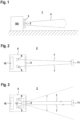
- FIG. 1 shows schematically an embodiment of the sensor arrangement 1 according to the invention.
- the sensor arrangement 1 has a sensor 2 which is mounted on a system 100 by means of a mounting system 3, so that the sensor 2 can be used to monitor a monitoring area in front of the system 100.
- the sensor 2 has a field of view 4 within which an object detection can be carried out.
- the sensor 2 is adjustably mounted on the mounting system 3.
- the mounting system 3 offers mechanical protection against damage.
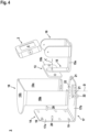
- FIG. 2 shows a first embodiment of the sensor 2 of the sensor arrangement 1 according to the invention.
- the sensor 2 has a housing 5 in which the sensor components of the sensor 2 are integrated.
- a front panel 6 is located in the housing 5.
- the sensor 2 comprises a transmitter unit 8 emitting radiation 7, a receiver unit 9 receiving radiation 7 and an evaluation unit 10 for evaluating received signals from the receiver unit 9.
- the radiation 7 emitted by the transmitter unit 8 in a fixed direction is guided through a front window 6 into the monitoring area. Radiation 7 reflected by an object 11 is guided back to the receiver unit 9.
- an object detection signal is generated depending on the received signals of the receiver unit 9, which indicates in particular whether an object 11 is present in the monitoring area or not.
- the opening angle of the radiation 7 and/or the viewing angle range of the receiver unit 9 determines the field of view 4 of the sensor 2.
- the sensor 2 can be designed as a distance sensor, whereby a pulse transit time method can be used to determine the distance.
- the sensor 2 can be designed as a radar sensor.
- the transmitter unit 8 is then formed by a transmitting antenna and the receiver unit 9 by a receiving antenna.
- the sensor 2 can also be an optical sensor 2.
- the transmitter unit 8 then consists of at least one transmitter emitting light beams, the receiver unit 9 of at least one receiver receiving light beams.
- the optical sensor 2 can also be designed as a camera sensor.
- the receiver unit 9 then consists of a matrix-shaped arrangement of receiving elements.
- Figure 3 shows another embodiment of the sensor 2.
- the sensor 2 according to Figure 3 is compared to the embodiment according to Figure 2 extended in such a way that a deflection unit 12 is provided with which the radiation 7 is periodically guided within a detection range which defines the field of view 4 of the sensor 2.
- the sensor 2 can again be designed as a radar sensor or optical sensor 2, wherein the optical sensor 2 has only one receiver as a receiver unit 9.
- the senor 2 can be designed as a safety sensor that is designed for use in safety-related applications.
- the safety sensor has a fail-safe structure. This can be implemented by a redundant evaluation unit 10, for example in the form of two cyclically monitoring computer units.
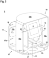
- Figure 4 shows in an exploded view the components of a first embodiment of the mounting system 3 of the sensor arrangement 1 according to the invention.
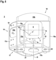
- the Figures 5 and 6 show the assembled mounting system 3 in different adjustment positions.
- the mounting system 3 comprises a primary holder 13, which forms an adjustment device for the sensor 2, and a secondary holder 14, which ensures mechanical protection for the sensor 2.
- the secondary bracket 14 is made of a more stable material than the primary bracket 13.
- the primary holder 13 consists of a plastic material and the secondary holder 14 consists of a metallic material.
- the primary holder 13 comprises a connecting element 15 consisting of an angle 15a and a plate 15b attached to a first arm of the angle 15a.
- a sensor holder 16 receiving the sensor 2 can be attached to the second arm of the angle 15a in such a way that the sensor holder 16 can be rotated by an axis A is rotatably mounted.
- the axis A runs in the longitudinal direction of the sensor holder 16.
- the sensor holder 16 is bow-shaped.
- the first arm of the angle 15a is mounted on the plate 15b so as to be pivotable about a pivot axis X.
- the sensor 2 itself is mounted on the sensor holder 16 so as to be pivotable about a pivot axis S1, whereby the pivot axis S1 runs perpendicular to the axis A.
- the Figures 5 and 6 show the sensor 2 in different rotational positions on the sensor holder 16.
- the secondary bracket 14 comprises a fastening element in the form of a mounting bracket 17 and a protective element in the form of a bracket 18.
- the fastening angle 17 forming the fastening element is designed for fastening to a base, in the present case a wall of the system 100.
- a first angle segment 17a of the fastening angle 17 is used for this purpose, in which fastening holes 19 are provided for fastening to a wall.
- the fastening means 20, which can be screws, are intended for fastening the primary holder 13.
- a second angle segment 17b of the fastening angle 17 forms a base plate on which the bracket 18 forming the protective element can be fastened in an adjustable position.
- rows of holes 21 are provided in the base plate, arranged concentrically to a pivot point.
- the holes 21 in each row of holes run along a circular arc.
- the holes 21 are circular.
- elongated holes can be provided.
- the bracket 18 can be adjusted around a rotation axis D.
- the rotation axis D can advantageously coincide with the axis A around which the sensor holder 16 can be rotated.
- the bracket 18 can be fixed to the base plate in discrete rotation positions. As the Figures 4 to 6 show, the bracket 18 is U-shaped, with two legs 18a being connected via a middle part 18b. To fix a rotational position of the bracket 18 to the base plate, a fixing element 22 is inserted through a hole 21 of a row of holes in the base plate and connected to the free end of a leg 18a.
- the fixing elements 22 can be formed by screws.
- the sensor holder 16 with the sensor 2 can be adjusted and fixed in a suitable rotational position by rotating it around the axis A, whereby the Figures 5 and 6 show different rotational positions of the sensor holder 16.
- the sensor 2 is thus adjusted to its desired position.
- the protective element i.e. the bracket 18 of the secondary holder 14 is adjusted to a corresponding rotational position so that the bracket 18 extends over the sensor holder 16 with the sensor 2 and protects it mechanically. Since the rotational position of the bracket 18 is adjusted to the rotational position of the sensor holder 16 with the sensor 2, the front side and thus the field of view 4 of the sensor 2 is not blocked by the bracket 18.
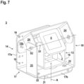
- Figure 7 shows a further development of the embodiment according to Figure 6 such that the protective element consists of a U-shaped lower bracket part 23 and a U-shaped upper bracket part 24, which are hingedly connected to one another, so that the upper bracket part 24 can be pivoted with respect to a pivot axis S2 with respect to the lower bracket part 23.
- the swivel axis S2 coincides with the swivel axis S1 of sensor 2.
- the bracket lower part 23 can be designed in accordance with the bracket 18 of the embodiments according to the Figures 4 to 6 be attached to the base plate in discrete rotational positions using the fixing elements 22.
- This protective element provides further improved mechanical protection of the sensor 2, since the inclination of the upper part of the bracket 24 can be adapted to the inclination of the sensor 2.
- Figure 8 shows a variant of the embodiment according to the Figures 4 to 6 , in which the sensor holder 16 with the sensor 2 can be tilted in two spatial directions.
Landscapes
- Engineering & Computer Science (AREA)
- General Engineering & Computer Science (AREA)
- Physics & Mathematics (AREA)
- General Physics & Mathematics (AREA)
- Mechanical Engineering (AREA)
- Radar, Positioning & Navigation (AREA)
- Remote Sensing (AREA)
- Computer Networks & Wireless Communication (AREA)
- Multimedia (AREA)
- Signal Processing (AREA)
- Geophysics And Detection Of Objects (AREA)
Abstract
Die Erfindung betrifft eine Sensoranordnung (1) mit einem ein Sichtfeld (4) aufweisenden Sensor (2) und mit einer primären Halterung (13), an welcher der Sensor (2) befestigbar ist. Die primäre Halterung (13) bildet eine Justagevorrichtung aus, mittels derer die Orientierung des Sichtfelds (4) des Sensors (2) einstellbar ist. Eine sekundäre Halterung (14) ist vorhanden, an welcher die primäre Halterung (13) befestigbar ist. Die sekundäre Halterung (14) bildet einen mechanischen Schutz für den Sensor (2) aus, wobei die sekundäre Halterung (14) an die Orientierung des Sichtfelds (4) des Sensors (2) anpassbar ist.
Description
- Die Erfindung betrifft eine Sensoranordnung.
- Eine derartige Sensoranordnung weist generell einen Sensor auf, der zur Erfassung bzw. Erkennung von Objekten eingesetzt wird. Insbesondere erfolgt mit dem Sensor eine Erfassung von Objekten in einem Überwachungsbereich. Abhängig davon, ob mit dem Sensor ein Objekt im Überwachungsbereich erfasst wird oder nicht, generiert der Sensor ein Objektfeststellungssignal, das beispielsweise an eine Steuerung einer Anlage ausgegeben wird.
- Der Sensor weist ein definiertes Sichtfeld auf, innerhalb dessen der Sensor Strahlung in den Überwachungsbereich sendet, bzw. Strahlung aus diesem empfängt, beispielsweise durch Reflexionen an zu detektierenden Objekten. Das Sichtfeld befindet sich an der Frontseite des Sensors.
- In bekannter Weise wird der Sensor mittels eines Montagesystems an einer Unterlage wie z.B. einer Wand oder an einer zu überwachenden Anlage montiert. Das Montagesystem ermöglicht eine Ausrichtung des Sensors, insbesondere eine Ausrichtung der Orientierung des Sichtfelds. Sobald die Ausrichtung beendet ist, wird der Sensor in der einjustierten Position mittels des Montagesystems lagefixiert.
- Um eine Ausrichtung des Sensors in einem möglichst großen Einstellbereich zu ermöglichen, wird der Sensor typisch nur an einer Seite, insbesondere seiner Rückseite mit dem Montagesystem verbunden.
- Der restliche Teil des Sensors ist frei zugänglich. Dies birgt die Gefahr von Beschädigungen des Sensors, beispielsweise durch Werkstücke, Fahrzeuge oder dergleichen, die gegen den Sensor stoßen.
- Prinzipiell kann um den Sensor als mechanischer Schutz eine stationäre Abdeckung gebaut werden, wobei die Abdeckung vorzugsweise alle Seiten des Sensors mit Ausnahme der Frontseite, wo das Sichtfeld des Sensors liegt, umgibt. Nachteilig hierbei ist jedoch, dass durch eine derartige Abdeckung die Orientierung des Sichtfelds des Sensors festgelegt ist und nicht mehr geändert werden kann.
- Zudem versperren derartige Abdeckungen oft den Zugang zu Bedienelementen am Sensor, wodurch Einstellungen des Sensors nicht mehr oder nur noch mit hohem Aufwand durchgeführt werden können.
- Der Erfindung liegt die Aufgabe zugrunde ein Montagesystem für Sensoren bereitzustellen, welches eine hohe Funktionalität aufweist.
- Zur Lösung dieser Aufgabe sind die Merkmale des Anspruchs 1 vorgesehen. Vorteilhafte Ausführungsformen und zweckmäßige Weiterbildungen der Erfindung sind in den abhängigen Ansprüchen beschrieben.
- Die Erfindung betrifft eine Sensoranordnung mit einem ein Sichtfeld aufweisenden Sensor und mit einer primären Halterung, an welcher der Sensor befestigbar ist. Die primäre Halterung bildet eine Justagevorrichtung aus, mittels derer die Orientierung des Sichtfelds des Sensors einstellbar ist. Eine sekundäre Halterung ist vorhanden, an welcher die primäre Halterung befestigbar ist. Die sekundäre Halterung bildet einen mechanischen Schutz für den Sensor aus und ist an die Orientierung des Sichtfelds des Sensors anpassbar.
- Mit der primären Halterung und sekundären Halterung wird ein Montagesystem für Sensoren bereitgestellt, welches bei einem kompakten Aufbau eine hohe Funktionalität gewährleistet.
- Die primäre Halterung bildet dabei eine Justagevorrichtung aus, mittels derer eine flexible, einfach Justage eines Sensors ermöglicht wird. Während eines Justagevorgangs kann die Orientierung des Sichtfelds des an der primären Halterung gelagerten Sensors in gewünschter Weise eingestellt werden, indem die primäre Halterung betätigt und entsprechend eingestellt wird. Nach erfolgter Justage wird die primäre Halterung mit dem Sensor in der gewünschten Position lagefixiert.
- Erfindungsgemäß ist zusätzlich zur primären Halterung eine sekundäre Halterung vorhanden, mit der ein mechanischer Schutz des Sensors erzielt wird, d.h. die sekundäre Halterung schützt den Sensor gegen mechanische Einflüsse. Insbesondere verhindert die sekundäre Halterung, dass Gegenstände wie Werkstücke, Fahrzeuge und dergleichen nicht direkt gegen den Sensor stoßen können, wodurch Beschädigungen des Sensors vermieden werden. Dabei ist die sekundäre Halterung so ausgebildet, dass diese die Stoßbelastungen auffängt, so dass ein Kontakt den Sensor mit anstoßenden Gegenständen vermieden wird.
- Ein wesentlicher Aspekt der Erfindung besteht darin, dass die sekundäre Halterung an die mit der primären Halterung eingestellte Orientierung des Sichtfelds des Sensors angepasst wird. Die sekundäre Halterung wird also an die eingestellte Orientierung des Sichtfelds des Sensors angepasst, so dass die sekundäre Halterung für unterschiedliche Orientierungen des Senors die mechanische Schutzwirkung des Sensors gewährleistet, ohne dass dadurch das Sichtfeld des Sensors beeinträchtigt wird.
- Gemäß einer vorteilhaften Ausführungsform der Erfindung ist die sekundäre Halterung mehrteilig ausgebildet. Mindestens ein Teil der sekundären Halterung ist an die Orientierung des Sichtfelds des Sensors anpassbar.
- Dies stellt eine effiziente Konstruktionsform dar, da nicht die gesamte sekundäre Halterung an die aktuelle Orientierung des Sensors angepasst werden muss.
- Besonders vorteilhaft weist die sekundäre Halterung ein Befestigungselement auf, das zur Befestigung an einer Unterlage ausgebildet ist. Die sekundäre Halterung weist ein an dem Befestigungselement positionsverstellbares Schutzelement auf.
- Daran angepasst weist die primäre Halterung ein mit der sekundären Halterung fest verbundenes Verbindungselement und einen den Sensor aufnehmenden Sensorhalter auf, wobei die Lage des Sensorhalters relativ zum Verbindungselement einstellbar ist.
- Mit dem Befestigungselement der sekundären Halterung wird das gesamte Montagesystem an einer Unterlage wie einer Wand eines Gebäudes oder einer Anlage befestigt. Mit dem Befestigungselement wird die sekundäre Halterung selbst an der Unterlage befestigt. Durch das Verbindungselement ist die primäre Halterung fest mit dem Befestigungselement der sekundären Halterung und damit auch mit der Unterlage fest verbunden.
- Durch eine Einstellung der Lage des Sensorhalters relativ zum Verbindungselement kann die Orientierung des Sichtfelds des Sensors eingestellt werden. Daran angepasst kann das Schutzelement der sekundären Halterung relativ zum Befestigungselement verstellt werden, so dass der Sensor durch das Schutzelement gegen mechanische Einflüsse geschützt ist, jedoch das Schutzelement das Sichtfeld nicht beeinträchtigt. In ihrer Endposition sind der Sensorhalter und das Schutzelement lagefixiert.
- Vorteilhaft ist der Sensorhalter um eine Achse drehbar. Durch die Drehbarkeit des Sensorhalters ist eine einfache Justage des Sensors möglich.
- Gemäß einer konstruktiv vorteilhaften Ausgestaltung ist das Befestigungselement ein Befestigungswinkel.
- Daran angepasst ist das Schutzelement in Form eines Bügels ausgebildet.
- Der Befestigungswinkel ist mit einem ersten Winkelsegment an der Unterlage befestigt. Auf dem zweiten, vorzugsweise senkrecht zum ersten Winkelsegment orientierten Winkelsegment ist der das Schutzelement bildende Bügel gelagert. Der Bügel ist im Wesentlichen u-förmig ausgebildet und weist zwei über ein Mittelteil verbundene Schenkel auf. Die freien Enden der Schenkel sind auf dem zweiten Winkelsegment befestigt.
- Die Schenkel und das Mittelteil erstrecken sich über den Sensorhalter mit dem Sensor und schützen so den Sensor gegen Beschädigungen.
- Die Positionsverstellbarkeit des Schutzelements ist vorteilhaft, dadurch realisiert, dass das Schutzelement um ein Drehachse drehbar gelagert ist.
- Vorteilhaft ist das Schutzelement in diskreten Drehpositionen am Befestigungselement arretierbar.
- Hierzu sind in einem Segment des Befestigungselements zwei konzentrisch zu einem Drehpunkt angeordnete Lochreihen oder konzentrisch angeordnete Langlöcher vorhanden. Zur Arretierung einer Drehposition des Schutzelements ist in jeweils mindestens ein Loch einer Lochreihe oder in mindestens ein Langloch ein mit der Unterseite des Schutzelements verbindbares Fixierelement einführbar.
- Die Lochreihen können entlang von Kreisbogensegmenten angeordnet sind. Die Löcher des Lochreihen können als kreisförmige Löcher oder Langlöcher ausgebildet sein. Die Fixierelemente können in Form von Schrauben ausgebildet sein.
- Durch die Länge der Lochreihen wird der Einstellbereich vorgegeben, der vorteilhaft ± 60°, besonders vorteilhaft ± 40° beträgt.
- Der Einstellbereich ist vorteilhaft an dem Einstellbereich der Drehungen des Sensorhalters der primären Halterung angepasst.
- Durch das Überstehen mindestens einer Kante des sekundären Halters wird der Sensor im primären Halter geschützt vor mechanischen Stößen durch vorbeigehende Menschen oder Objekte auf vorbeifahrenden Fahrzeugen auch wenn der sekundäre Halter um eine oder zwei Achsen verdreht montiert ist.
- Weiter vorteilhaft verläuft die Achse, um welche der Sensorhalter drehbar ist, parallel zur Drehachse des Schutzelements. Dadurch kann die Drehposition des Schutzelements an die Drehposition des Sensorhalters genau angepasst werden.
- Gemäß einer alternativen Ausgestaltung ist der Sensorhalter in zwei Raumrichtungen neigungsverstellbar.
- Die Verstellbarkeit des Schutzelements ist auch in diesem Fall so an die Verstellbarkeit des Sensorhalters angepasst, dass das Schutzelement stets den Sensorhalter mit dem Sensor gegen mechanische Beschädigungen schützt.
- Gemäß einer vorteilhaften Weiterbildung ist der Sensorhalter mit dem Sensor nicht nur um die Achse drehbar. Zusätzlich ist der Sensor an dem Sensorhalter um eine Schwenkachse und der Sensorhalter um eine Platte um die Achse X schwenkbar gelagert.
- Vorteilhaft verläuft die Schwenkachse senkrecht zur Längsachse des Sensorhalters.
- Damit kann die Lage des Sensors in zwei oder drei Raumrichtungen verstellt werden.
- Daran angepasst ist das Schutzelement mehrteilig ausgebildet. Ein oberes Teil des Schutzelements ist bezüglich einer Schwenkachse gegenüber einem unteren Teil des Schutzelements, das mit dem Befestigungselement verbunden ist, schwenkbar. Zweckmäßig verläuft die Schwenkachse senkrecht zur Drehachse.
- Das Schutzelement kann somit exakt an die Position des am Sensorhalter gelagerten Sensors angepasst werden, um diesen gegen mechanische Beschädigungen zu schützen.
- Da nur die sekundäre Halterung einen Schutz gegen mechanische Belastungen gewährleisten muss, besteht vorteilhaft besteht die sekundäre Halterung aus einem stabileren Material als die primäre Halterung.
- Beispielsweise besteht die primäre Halterung aus einem Kunststoff und die sekundäre Halterung aus einem metallischen Werkstoff.
- Natürlich sind auch andere Materialienkombinationen denkbar. So kann z.B. die sekundäre Halterung aus einem härteren, widerstandfähigeren Kunststoff als die primäre Halterung bestehen.
- Gemäß einer vorteilhaften Ausführungsform ist der Sensor ein Radarsensor.
- Alternativ ist der Sensor ein optischer Sensor.
- Insbesondere ist der optische Sensor ein LIDAR-Sensor oder ein Kamerasensor.
- Gemäß einer vorteilhaften Ausgestaltung ist der Sensor ein Sicherheitssensor.
- Der Sicherheitssensor kann in sicherheitstechnischen Applikationen, insbesondere im Bereich des Personenschutzes, eingesetzt werden und weist hierzu einen fehlersicheren Aufbau auf.
- Die Erfindung wird im Folgenden anhand der Zeichnungen erläutert. Es zeigen:
- Figur 1:
- Schematische Darstellung der erfindungsgemäßen Sensoranordnung.
- Figur 2:
- Erstes Ausführungsbeispiel eines Sensors für die Sensoranordnung gemäß
Figur 1 . - Figur 3:
- Zweites Ausführungsbeispiel eines Sensors für die Sensoranordnung gemäß
Figur 1 . - Figur 4:
- Ausführungsbeispiel eines Montagesystems für die Sensoranordnung gemäß
Figur 1 in einer Explosionsdarstellung. - Figur 5:
- Montagesystem gemäß
Figur 4 in einer ersten Justageposition. - Figur 6:
- Montagesystem gemäß
Figur 4 in einer zweiten Justageposition. - Figur 7:
- Zweites Ausführungsbeispiel des Montagesystems.
- Figur 8:
- Drittes Ausführungsbeispiel des Montagesystems.
-
Figur 1 zeigt schematisch ein Ausführungsbeispiel der erfindungsgemäßen Sensoranordnung 1. Die Sensoranordnung 1 weist einen Sensor 2 auf, der mittels eines Montagesystems 3 an einer Anlage 100 montiert ist, so dass mit dem Sensor 2 ein Überwachungsbereich im Vorfeld der Anlage 100 überwacht werden kann. Der Sensor 2 weist ein Sichtfeld 4 auf, innerhalb dessen eine Objekterfassung durchgeführt werden kann. - Der Sensor 2 ist am Montagesystem 3 justierbar gelagert. Zudem bietet das Montagesystem 3 einen mechanischen Schutz gegen Beschädigungen.
-
Figur 2 zeigt ein erstes Ausführungsbeispiel des Sensors 2 der erfindungsgemäßen Sensoranordnung 1. Der Sensor 2 weist ein Gehäuse 5 auf, in welchem die Sensorkomponenten des Sensors 2 integriert sind. In der Frontwand des Gehäuses 5 befindet sich eine Frontscheibe 6. Der Sensor 2 umfasst eine Strahlung 7 emittierende Sendereinheit 8, eine Strahlung 7 empfangende Empfängereinheit 9 und eine Auswerteeinheit 10 zur Auswertung von Empfangssignalen der Empfängereinheit 9. - Die von der Sendereinheit 8 in einer feststehenden Richtung emittierte Strahlung 7 wird durch eine Frontscheibe 6 in den Überwachungsbereich geführt. Von einem Objekt 11 reflektierte Strahlung 7 wird zurück zur Empfängereinheit 9 geführt. In der Auswerteeinheit 10 wird abhängig von den Empfangssignalen der Empfängereinheit 9 ein Objektfeststellungssignal generiert, das insbesondere angibt, ob ein Objekt 11 im Überwachungsbereich vorhanden ist oder nicht.
- Der Öffnungswinkel der Strahlung 7 und/oder der Sichtwinkelbereich der Empfängereinheit 9 bestimmt das Sichtfeld 4 des Sensors 2.
- Der Sensor 2 kann als Distanzsensor ausgebildet sein, wobei zur Distanzbestimmung ein Impuls-Laufzeit-Verfahren eingesetzt werden kann.
- Der Sensor 2 kann als Radarsensor ausgebildet sein. Dann ist die Sendereinheit 8 von einer Sendeantenne und die Empfängereinheit 9 von einer Empfangsantenne gebildet.
- Der Sensor 2 kann auch ein optischer Sensor 2 sein. Die Sendereinheit 8 besteht dann aus wenigstens einem Lichtstrahlen emittierenden Sender, die Empfängereinheit 9 aus wenigstens einem Lichtstrahlen empfangenden Empfänger. Der optische Sensor 2 kann auch als Kamerasensor ausgebildet sein. Dann besteht die Empfängereinheit 9 aus einer matrixförmigen Anordnung von Empfangselementen.
-
Figur 3 zeigt ein weiteres Ausführungsbeispiel des Sensors 2. Der Sensor 2 gemäßFigur 3 ist gegenüber der Ausführungsform gemäßFigur 2 dahingehend erweitert, dass eine Ablenkeinheit 12 vorhanden ist, mit der die Strahlung 7 periodisch innerhalb eines Erfassungsbereichs geführt ist, welcher das Sichtfeld 4 des Sensors 2 definiert. - Der Sensor 2 kann wieder als Radarsensor oder optischer Sensor 2 ausgebildet sein, wobei der optische Sensor 2 als Empfängereinheit 9 nur einen Empfänger aufweist.
- Generell kann der Sensor 2 als Sicherheitssensor ausgebildet sein, der für den Einsatz in sicherheitstechnischen Applikationen ausgebildet ist. Hierzu weist der Sicherheitssensor einen fehlersicheren Aufbau auf. Dies kann durch eine redundante Auswerteeinheit 10, beispielsweise in Form zweier sich zyklisch überwachender Rechnereinheiten, realisiert werden.
-
Figur 4 zeigt in einer Explosionsdarstellung die Komponenten eines ersten Ausführungsbeispiels des Montagesystems 3 der erfindungsgemäßen Sensoranordnung 1. DieFiguren 5 und6 zeigen das zusammengebaute Montagesystem 3 in unterschiedlichen Justagepositionen. - Das Montagesystem 3 umfasst eine primäre Halterung 13, die eine Justagevorrichtung für den Sensor 2 ausbildet, und eine sekundäre Halterung 14, die einen mechanischen Schutz für den Sensor 2 gewährleistet.
- Vorteilhaft besteht die sekundäre Halterung 14 aus einem stabileren Material als die primäre Halterung 13.
- Insbesondere besteht die primäre Halterung 13 aus einem Kunststoff und die sekundäre Halterung 14 aus einem metallischen Werkstoff.
- Die primäre Halterung 13 umfasst ein Verbindungselement 15 bestehend aus einem Winkel 15a und einer an einen ersten Arm des Winkels 15a befestigten Platte 15b. Auf dem zweiten Arm des Winkels 15a kann ein den Sensor 2 aufnehmenden Sensorhalter 16 so befestigt werden, dass der Sensorhalter 16 um eine Achse A drehbar gelagert ist. Die Achse A verläuft in Längsrichtung des Sensorhalters 16. Der Sensorhalter 16 ist bügelförmig ausgebildet.
- Der erste Arm des Winkels 15a ist um eine Schwenkachse X schwenkbar an der Platte 15b gelagert.
- Der Sensor 2 selbst ist am Sensorhalter 16 um eine Schwenkachse S1 schwenkbar gelagert, wobei die Schwenkachse S1 senkrecht zur Achse A verläuft. Die
Figuren 5 und6 zeigen den Sensor 2 in unterschiedlichen Drehpositionen am Sensorhalter 16. - Die sekundäre Halterung 14 umfasst ein Befestigungselement in Form eines Befestigungswinkels 17 und ein Schutzelement in Form eines Bügels 18.
- Der das Befestigungselement bildende Befestigungswinkel 17 ist zur Befestigung an einer Unterlage, im vorliegenden Fall einer Wand der Anlage 100 ausgebildet.
- Hierzu dient ein erstes Winkelsegment 17a des Befestigungswinkels 17, in dem Befestigungslöcher 19 vorgesehen sind zur Befestigung an einer Wand. Die Befestigungsmittel 20, die schrauben sein können, sind zur Befestigung des primären Halters 13 bestimmt.
- Ein zweites Winkelsegment 17b des Befestigungswinkels 17 bildet eine Grundplatte, auf der der das Schutzelement bildende Bügel 18 positionsverstellbar befestigt werden kann.
- Hierzu sind in der Grundplatte konzentrisch zu einem Drehpunkt angeordnete Lochreihen mit Löchern 21 vorgesehen. Die Löcher 21 jeder Lochreihe verlaufen jeweils entlang eines Kreisbogens. Die Löcher 21 sind im vorliegenden Fall kreisförmig ausgebildet. Alternativ können Langlöcher vorgesehen sein.
- Damit wird eine Verstellbarkeit des Bügels 18 um eine Drehachse D erzielt. Die Drehachse D kann vorteilhaft mit der Achse A, um die der Sensorhalter 16 gedreht werden kann, zusammenfallen. Der Bügel 18 kann in diskreten Drehpositionen an der Grundplatte fixiert werden. Wie die
Figuren 4 bis 6 zeigen, ist der Bügel 18 u-förmig ausgebildet, wobei zwei Schenkel 18a über ein Mittelteil 18b verbunden sind. Zur Fixierung einer Drehposition des Bügels 18 an der Grundplatte wird jeweils ein Fixierelement 22 durch ein Loch 21 einer Lochreihe der Grundplatte gesteckt und mit dem freien Ende eines Schenkels 18a verbunden. Die Fixierelemente 22 können von Schrauben gebildet sein. - Wie die
Figuren 5 und6 zeigen, kann in einem Justagevorgang der Sensorhalter 16 mit dem Sensor 2 in einer geeigneten Drehposition durch Drehen um die Achse A eingestellt und lagefixiert werden, wobei dieFiguren 5 und6 unterschiedliche Drehpositionen des Sensorhalters 16 zeigen. Damit ist der Sensor 2 in seiner Solllage justiert. - Daran angepasst wird das Schutzelement, d.h. der Bügel 18 der sekundären Halterung 14 in eine entsprechende Drehposition eingebracht, so dass sich der Bügel 18 über den Sensorhalter 16 mit dem Sensor 2 erstreckt und diesen mechanisch schützt. Da die Drehposition des Bügels 18 an die Drehposition des Sensorhalters 16 mit dem Sensor 2 angepasst ist, wird die Frontseite und damit das Sichtfeld 4 des Sensors 2 durch den Bügel 18 nicht versperrt.
-
Figur 7 zeigt eine Weiterbildung der Ausführungsform gemäßFigur 6 derart, dass das Schutzelement aus einem u-förmigen Bügelunterteils 23 und einem u-förmigen Bügeloberteil 24 besteht, die gelenkig miteinander verbunden sind, so dass das Bügeloberteil 24 bezüglich einer Schwenkachse S2 bezüglich des Bügelunterteils 23 geschwenkt werden kann. - Die Schwenkachse S2 fällt mit der Schwenkachse S1 des Sensors 2 zusammen.
- Das Bügelunterteil 23 kann entsprechend dem Bügel 18 der Ausführungsformen gemäß den
Figuren 4 bis 6 mit den Fixierelementen 22 in diskreten Drehpositionen an der Grundplatte befestigt werden. - Dieses Schutzelement sorgt für einen weiter verbesserten mechanischen Schutz des Sensors 2, da die Neigung des Bügeloberteils 24 an die Neigung des Sensors 2 angepasst werden kann.
-
Figur 8 zeigt eine Variante der Ausführungsform gemäß denFiguren 4 bis 6 , bei welcher der Sensorhalter 16 mit dem Senor 2 in zwei Raumrichtungen geneigt werden kann. -
- (1) Sensoranordnung
- (2) Sensor
- (3) Montagesystem
- (4) Sichtfeld
- (5) Gehäuse
- (6) Frontscheibe
- (7) Strahlung
- (8) Sendereinheit
- (9) Empfängereinheit
- (10) Auswerteeinheit
- (11) Objekt
- (12) Ablenkeinheit
- (13) primäre Halterung
- (14) sekundäre Halterung
- (15) Verbindungselement
- (15a) Winkel
- (15b) Platte
- (16) Sensorhalter
- (17) Befestigungswinkel
- (17a) Winkelsegment
- (17b) Winkelsegment
- (18) Bügel
- (18a) Schenkel
- (18b) Mittelteil
- (19) Befestigungsfläche
- (20) Befestigungsmittel
- (21) Loch
- (22) Fixierelement
- (23) Bügelunterteil
- (24) Bügeloberteil
- (100) Anlage
- (A) Achse
- (D) Drehachse
- (S1) Schwenkachse
- (S2) Schwenkachse
- (X) Schwenkachse
Claims (15)
- Sensoranordnung (1) mit einem ein Sichtfeld (4) aufweisenden Sensor (2) und mit einer primären Halterung (13), an welcher der Sensor (2) befestigbar ist, wobei die primäre Halterung (13) eine Justagevorrichtung ausbildet, mittels derer die Orientierung des Sichtfelds (4) des Sensors (2) einstellbar ist, dadurch gekennzeichnet, dass eine sekundäre Halterung (14) vorhanden ist, an welcher die primäre Halterung (13) befestigbar ist, wobei die sekundäre Halterung (14) einen mechanischen Schutz für den Sensor (2) ausbildet, und wobei die sekundäre Halterung (14) an die Orientierung des Sichtfelds (4) des Sensors (2) anpassbar ist.
- Sensoranordnung (1) nach Anspruch 1, dadurch gekennzeichnet, dass die sekundäre Halterung (14) mehrteilig ausgebildet ist, wobei mindestens ein Teil der sekundären Halterung (14) an die Orientierung des Sichtfelds (4) des Sensors (2) anpassbar ist.
- Sensoranordnung (1) nach Anspruch 2, dadurch gekennzeichnet, dass die sekundäre Halterung (14) ein Befestigungselement aufweist, das zur Befestigung an einer Unterlage ausgebildet ist, und dass die sekundäre Halterung (14) ein an dem Befestigungselement positionsverstellbares Schutzelement aufweist.
- Sensoranordnung (1) nach Anspruch 3, dadurch gekennzeichnet, dass das Befestigungselement ein Befestigungswinkel (17) ist, und/oder dass das Schutzelement in Form eines Bügels (18) ausgebildet ist.
- Sensoranordnung (1) nach einem der Ansprüche 3 und 4, dadurch gekennzeichnet, dass das Schutzelement bezüglich einer Drehachse (D) drehbar gelagert ist, wobei das Schutzelement in diskreten Drehpositionen am Befestigungselement arretierbar ist.
- Sensoranordnung (1) nach Anspruch 5, dadurch gekennzeichnet, dass in einem Segment des Befestigungselements zwei konzentrisch zu einem Drehpunkt angeordnete Lochreihen oder Langlöcher vorhanden sind, wobei zur Arretierung einer Drehposition des Schutzelements in jeweils mindestens ein Loch (21) einer Lochreihe oder Langlöcher ein mit der Unterseite des Schutzelements verbindbares Fixierelement (22) einführbar ist.
- Sensoranordnung (1) nach einem der Ansprüche 3 bis 6, dadurch gekennzeichnet, dass das Schutzelement mehrteilig ausgebildet ist, wobei ein oberes Teil des Schutzelements bezüglich einer Schwenkachse (S2) gegenüber einem unteren Teil des Schutzelements, das mit dem Befestigungselement verbunden ist, schwenkbar ist.
- Sensoranordnung (1) nach einem der Ansprüche 1 bis 7, dadurch gekennzeichnet, dass die primäre Halterung (13) ein mit der sekundären Halterung (14) verbundenes Verbindungselement (15) und einen den Sensor (2) aufnehmenden Sensorhalter (16) aufweist, wobei die Lage des Sensorhalters (16) relativ zum Verbindungselement (15) einstellbar ist.
- Sensoranordnung (1) nach Anspruch 8, dadurch gekennzeichnet, dass der Sensorhalter (16) um eine Achse (A) drehbar ist, und/oder dass der Sensorhalter (16) in zwei Raumrichtungen neigungsverstellbar ist.
- Sensoranordnung (1) nach einem der Ansprüche 6 und 9, dadurch gekennzeichnet, dass die Achse (A) parallel zur Drehachse (D) des Schutzelements verläuft, und/oder dass der Sensor (2) an dem Sensorhalter (16) um eine Schwenkachse (S1) schwenkbar gelagert ist, wobei die Schwenkachse (S 1) senkrecht zur Längsachse des Sensorhalters (16) verläuft.
- Sensoranordnung (1) nach einem der Ansprüche 8 bis 10, dadurch gekennzeichnet, dass das Verbindungselement (15) aus einem Winkel (15a) und einer Platte (15b) an der sekundären Halterung (14) befestigt ist, wobei der Winkel (15a) mit einem ersten Arm um eine Schwenkachse (X) schwenkbar an der Platte (15b) gelagert ist, und wobei auf dem zweiten Arm des Winkels (15a) der Sensorhalter (16) gelagert ist.
- Sensoranordnung (1) nach einem der Ansprüche 3 bis 11, dadurch gekennzeichnet, dass Sensorlagen des Sensors (2) an der primären Halterung (13) innerhalb vorgegebener Einstellbereiche veränderbar sind, und/oder dass Einstellbereiche des Schutzelements an die Einstellbereiche des Sensors (2) angepasst sind.
- Sensoranordnung (1) nach einem der Ansprüche 1 bis 12, dadurch gekennzeichnet, dass die sekundäre Halterung (14) aus einem stabileren Material als die primäre Halterung (13) besteht.
- Sensoranordnung (1) nach einem der Ansprüche 1 bis 13, dadurch gekennzeichnet, dass der Sensor (2) ein Radarsensor oder ein optischer Sensor (2) ist.
- Sensoranordnung (1) nach einem der Ansprüche 1 bis 14, dadurch gekennzeichnet, dass der Sensor (2) ein Sicherheitssensor ist.
Applications Claiming Priority (1)
| Application Number | Priority Date | Filing Date | Title |
|---|---|---|---|
| DE202023103660.0U DE202023103660U1 (de) | 2023-06-30 | 2023-06-30 | Sensoranordnung |
Publications (1)
| Publication Number | Publication Date |
|---|---|
| EP4484997A1 true EP4484997A1 (de) | 2025-01-01 |
Family
ID=90362176
Family Applications (1)
| Application Number | Title | Priority Date | Filing Date |
|---|---|---|---|
| EP24161635.8A Pending EP4484997A1 (de) | 2023-06-30 | 2024-03-06 | Sensoranordnung |
Country Status (3)
| Country | Link |
|---|---|
| US (1) | US20250004096A1 (de) |
| EP (1) | EP4484997A1 (de) |
| DE (1) | DE202023103660U1 (de) |
Citations (5)
| Publication number | Priority date | Publication date | Assignee | Title |
|---|---|---|---|---|
| CN103116156A (zh) * | 2013-01-24 | 2013-05-22 | 上海胜迈机电科技有限公司 | 激光扫描测距仪用角度可调式防护装置 |
| EP3171070A1 (de) * | 2015-11-23 | 2017-05-24 | Sick Ag | Halterung |
| US20200114851A1 (en) * | 2018-10-10 | 2020-04-16 | Stocked Robotics, Inc. | Non-destructive kit mounting system for driverless industrial vehicles |
| CN212158492U (zh) * | 2020-05-22 | 2020-12-15 | 安徽合力股份有限公司 | 一种具有安装防护机构的激光扫描装置 |
| CN214930710U (zh) * | 2021-07-20 | 2021-11-30 | 翼侠电子科技(上海)股份有限公司 | 一种无人机测绘数据采集装置 |
Family Cites Families (6)
| Publication number | Priority date | Publication date | Assignee | Title |
|---|---|---|---|---|
| US6762790B1 (en) * | 2002-12-20 | 2004-07-13 | Bendix Commercial Vehicle Systems Llc | Universal camera bracket that allows 180 degree of pitch adjustment |
| DE202004014825U1 (de) * | 2004-09-21 | 2004-11-11 | Waeco International Gmbh | Schutzvorrichtung für fest montierte Kameras wie insbesondere Rückfahrkameras von Lastkraftwagen u.dgl. sowie Kameraanordnung und Fahrzeug mit einer solchen Kameraanordnung |
| DE202009010193U1 (de) * | 2009-07-27 | 2010-12-09 | Dometic Waeco International Gmbh | Außenkamera für Kraftfahrzeuge |
| DE102012104266A1 (de) * | 2012-05-16 | 2013-11-21 | Alfred Ottowitz | Schutzvorrichtung für Anzeigegeräte |
| WO2015088396A1 (en) * | 2013-12-11 | 2015-06-18 | Volvo Truck Corporation | Adjustable bracket and method for mounting a detector on a vehicle |
| DE102017105213A1 (de) * | 2017-03-13 | 2018-09-13 | Connaught Electronics Ltd. | Positions-Verstellvorrichtung für eine Kamera mit einem eigenen Kameragehäuse eines Kraftfahrzeugs, mit spezifischen Azimutpositionen für die Kamera, Einrichtung für ein Kraftfahrzeug sowie Kraftfahrzeug |
-
2023
- 2023-06-30 DE DE202023103660.0U patent/DE202023103660U1/de active Active
-
2024
- 2024-03-06 EP EP24161635.8A patent/EP4484997A1/de active Pending
- 2024-06-19 US US18/747,568 patent/US20250004096A1/en active Pending
Patent Citations (5)
| Publication number | Priority date | Publication date | Assignee | Title |
|---|---|---|---|---|
| CN103116156A (zh) * | 2013-01-24 | 2013-05-22 | 上海胜迈机电科技有限公司 | 激光扫描测距仪用角度可调式防护装置 |
| EP3171070A1 (de) * | 2015-11-23 | 2017-05-24 | Sick Ag | Halterung |
| US20200114851A1 (en) * | 2018-10-10 | 2020-04-16 | Stocked Robotics, Inc. | Non-destructive kit mounting system for driverless industrial vehicles |
| CN212158492U (zh) * | 2020-05-22 | 2020-12-15 | 安徽合力股份有限公司 | 一种具有安装防护机构的激光扫描装置 |
| CN214930710U (zh) * | 2021-07-20 | 2021-11-30 | 翼侠电子科技(上海)股份有限公司 | 一种无人机测绘数据采集装置 |
Non-Patent Citations (2)
| Title |
|---|
| ANONYMOUS: "nanoScan3 mounting kits", 10 June 2022 (2022-06-10), pages 1 - 8, XP093189184, Retrieved from the Internet <URL:https://cdn.sick.com/media/docs/8/78/878/mounting_instructions_nanoscan3_mounting_kits_de_en_im0089878.pdf> [retrieved on 20240724] * |
| MURGA GAIZKA ET AL: "Design solutions for dome and main structure (mount) of giant telescopes", PROCEEDINGS OF SPIE; [PROCEEDINGS OF SPIE ISSN 0277-786X VOLUME 10524], SPIE, US, vol. 9906, 27 July 2016 (2016-07-27), pages 99060C - 99060C, XP060074224, ISBN: 978-1-5106-1533-5, DOI: 10.1117/12.2233502 * |
Also Published As
| Publication number | Publication date |
|---|---|
| DE202023103660U1 (de) | 2024-08-19 |
| US20250004096A1 (en) | 2025-01-02 |
Similar Documents
| Publication | Publication Date | Title |
|---|---|---|
| EP2128965B1 (de) | Drehrichtungsanzeiger | |
| DE102021129914B3 (de) | Türband | |
| DE10246031A1 (de) | Positions- und/oder Bewegungsfühler mit Überlastungsschutz | |
| DE202023103660U1 (de) | Sensoranordnung | |
| EP1903418A1 (de) | Vorrichtung zur Umwandlung mechanischer Bewegungen in elektrische Signale | |
| EP1024238B1 (de) | Vorrichtung zum Erfassen der Stellung eines Schlossriegels | |
| EP1876320A1 (de) | Justierbarer Lichtschrankensender | |
| DE102015120249B4 (de) | Halterung | |
| EP1903165A2 (de) | Fenster- oder Türgriff | |
| EP1591802B1 (de) | Vorrichtung zur Ausrichtung eines optischen Sensors | |
| DE102018215995A1 (de) | Sensorhalter für ein Fahrzeug | |
| WO2010081178A1 (de) | Auslösesensor für einen möbelantrieb | |
| EP1102086B1 (de) | Optoelektronische Vorrichtung | |
| DE102007040692B4 (de) | Optoelektronische Schutzeinrichtung | |
| DE19924056A1 (de) | Halterung für ein justierbares Gehäuse | |
| EP2847406A1 (de) | Stützeinrichtung für eine geschlossene klappe eines fahrzeugs, insbesondere heckklappe eines kraftfahrzeugs | |
| EP2415679B1 (de) | Ultraschallsensor | |
| EP3034751B1 (de) | Montageplatte | |
| EP0485870B1 (de) | Kraftsensorsystem zur Erfassung von Zugkräften | |
| DE2811413A1 (de) | Naeherungsschalter | |
| DE102014102856B3 (de) | Federgesicherte Befestigungseinrichtung für einen Sicherheitsgurtbeschlag | |
| EP2551533B1 (de) | Sensor | |
| DE19700478A1 (de) | Befestigungsvorrichtung | |
| DE102010048173B3 (de) | Verfahren zur Justierung eines Sensorkopfes einer Nadelüberwachungseinrichtung und Nadelüberwachungseinrichtung | |
| DE202024107387U1 (de) | Überwachungseinrichtung |
Legal Events
| Date | Code | Title | Description |
|---|---|---|---|
| PUAI | Public reference made under article 153(3) epc to a published international application that has entered the european phase |
Free format text: ORIGINAL CODE: 0009012 |
|
| STAA | Information on the status of an ep patent application or granted ep patent |
Free format text: STATUS: REQUEST FOR EXAMINATION WAS MADE |
|
| 17P | Request for examination filed |
Effective date: 20241010 |
|
| AK | Designated contracting states |
Kind code of ref document: A1 Designated state(s): AL AT BE BG CH CY CZ DE DK EE ES FI FR GB GR HR HU IE IS IT LI LT LU LV MC ME MK MT NL NO PL PT RO RS SE SI SK SM TR |
|
| P01 | Opt-out of the competence of the unified patent court (upc) registered |
Free format text: CASE NUMBER: APP_1934/2025 Effective date: 20250113 |