EP4482017A2 - Motorsicherheitssteuerungsverfahren und roboter - Google Patents
Motorsicherheitssteuerungsverfahren und roboter Download PDFInfo
- Publication number
- EP4482017A2 EP4482017A2 EP24161983.2A EP24161983A EP4482017A2 EP 4482017 A2 EP4482017 A2 EP 4482017A2 EP 24161983 A EP24161983 A EP 24161983A EP 4482017 A2 EP4482017 A2 EP 4482017A2
- Authority
- EP
- European Patent Office
- Prior art keywords
- motor
- signal
- speed
- sub
- monitor
- Prior art date
- Legal status (The legal status is an assumption and is not a legal conclusion. Google has not performed a legal analysis and makes no representation as to the accuracy of the status listed.)
- Pending
Links
Images




Classifications
-
- H—ELECTRICITY
- H02—GENERATION; CONVERSION OR DISTRIBUTION OF ELECTRIC POWER
- H02P—CONTROL OR REGULATION OF ELECTRIC MOTORS, ELECTRIC GENERATORS OR DYNAMO-ELECTRIC CONVERTERS; CONTROLLING TRANSFORMERS, REACTORS OR CHOKE COILS
- H02P6/00—Arrangements for controlling synchronous motors or other dynamo-electric motors using electronic commutation dependent on the rotor position; Electronic commutators therefor
- H02P6/14—Electronic commutators
- H02P6/16—Circuit arrangements for detecting position
- H02P6/17—Circuit arrangements for detecting position and for generating speed information
-
- H—ELECTRICITY
- H02—GENERATION; CONVERSION OR DISTRIBUTION OF ELECTRIC POWER
- H02P—CONTROL OR REGULATION OF ELECTRIC MOTORS, ELECTRIC GENERATORS OR DYNAMO-ELECTRIC CONVERTERS; CONTROLLING TRANSFORMERS, REACTORS OR CHOKE COILS
- H02P6/00—Arrangements for controlling synchronous motors or other dynamo-electric motors using electronic commutation dependent on the rotor position; Electronic commutators therefor
- H02P6/14—Electronic commutators
- H02P6/16—Circuit arrangements for detecting position
-
- H—ELECTRICITY
- H02—GENERATION; CONVERSION OR DISTRIBUTION OF ELECTRIC POWER
- H02P—CONTROL OR REGULATION OF ELECTRIC MOTORS, ELECTRIC GENERATORS OR DYNAMO-ELECTRIC CONVERTERS; CONTROLLING TRANSFORMERS, REACTORS OR CHOKE COILS
- H02P6/00—Arrangements for controlling synchronous motors or other dynamo-electric motors using electronic commutation dependent on the rotor position; Electronic commutators therefor
- H02P6/04—Arrangements for controlling or regulating the speed or torque of more than one motor
-
- B—PERFORMING OPERATIONS; TRANSPORTING
- B25—HAND TOOLS; PORTABLE POWER-DRIVEN TOOLS; MANIPULATORS
- B25J—MANIPULATORS; CHAMBERS PROVIDED WITH MANIPULATION DEVICES
- B25J5/00—Manipulators mounted on wheels or on carriages
- B25J5/007—Manipulators mounted on wheels or on carriages mounted on wheels
-
- B—PERFORMING OPERATIONS; TRANSPORTING
- B25—HAND TOOLS; PORTABLE POWER-DRIVEN TOOLS; MANIPULATORS
- B25J—MANIPULATORS; CHAMBERS PROVIDED WITH MANIPULATION DEVICES
- B25J9/00—Program-controlled manipulators
- B25J9/16—Program controls
- B25J9/1674—Program controls characterised by safety, monitoring, diagnostic
-
- B—PERFORMING OPERATIONS; TRANSPORTING
- B60—VEHICLES IN GENERAL
- B60L—PROPULSION OF ELECTRICALLY-PROPELLED VEHICLES; SUPPLYING ELECTRIC POWER FOR AUXILIARY EQUIPMENT OF ELECTRICALLY-PROPELLED VEHICLES; ELECTRODYNAMIC BRAKE SYSTEMS FOR VEHICLES IN GENERAL; MAGNETIC SUSPENSION OR LEVITATION FOR VEHICLES; MONITORING OPERATING VARIABLES OF ELECTRICALLY-PROPELLED VEHICLES; ELECTRIC SAFETY DEVICES FOR ELECTRICALLY-PROPELLED VEHICLES
- B60L15/00—Methods, circuits, or devices for controlling the traction-motor speed of electrically-propelled vehicles
- B60L15/20—Methods, circuits, or devices for controlling the traction-motor speed of electrically-propelled vehicles for control of the vehicle or its driving motor to achieve a desired performance, e.g. speed, torque, programmed variation of speed
-
- G—PHYSICS
- G05—CONTROLLING; REGULATING
- G05D—SYSTEMS FOR CONTROLLING OR REGULATING NON-ELECTRIC VARIABLES
- G05D1/00—Control of position, course, altitude or attitude of land, water, air or space vehicles, e.g. using automatic pilots
- G05D1/60—Intended control result
- G05D1/617—Safety or protection, e.g. defining protection zones around obstacles or avoiding hazards
- G05D1/622—Obstacle avoidance
-
- H—ELECTRICITY
- H02—GENERATION; CONVERSION OR DISTRIBUTION OF ELECTRIC POWER
- H02K—DYNAMO-ELECTRIC MACHINES
- H02K11/00—Structural association of dynamo-electric machines with electric components or with devices for shielding, monitoring or protection
- H02K11/20—Structural association of dynamo-electric machines with electric components or with devices for shielding, monitoring or protection for measuring, monitoring, testing, protecting or switching
- H02K11/21—Devices for sensing speed or position, or actuated thereby
- H02K11/215—Magnetic effect devices, e.g. Hall-effect or magneto-resistive elements
-
- H—ELECTRICITY
- H02—GENERATION; CONVERSION OR DISTRIBUTION OF ELECTRIC POWER
- H02K—DYNAMO-ELECTRIC MACHINES
- H02K11/00—Structural association of dynamo-electric machines with electric components or with devices for shielding, monitoring or protection
- H02K11/20—Structural association of dynamo-electric machines with electric components or with devices for shielding, monitoring or protection for measuring, monitoring, testing, protecting or switching
- H02K11/21—Devices for sensing speed or position, or actuated thereby
- H02K11/22—Optical devices
-
- H—ELECTRICITY
- H02—GENERATION; CONVERSION OR DISTRIBUTION OF ELECTRIC POWER
- H02K—DYNAMO-ELECTRIC MACHINES
- H02K21/00—Synchronous motors having permanent magnets; Synchronous generators having permanent magnets
- H02K21/12—Synchronous motors having permanent magnets; Synchronous generators having permanent magnets with stationary armatures and rotating magnets
- H02K21/14—Synchronous motors having permanent magnets; Synchronous generators having permanent magnets with stationary armatures and rotating magnets with magnets rotating within the armatures
- H02K21/20—Synchronous motors having permanent magnets; Synchronous generators having permanent magnets with stationary armatures and rotating magnets with magnets rotating within the armatures having windings each turn of which co-operates only with poles of one polarity, e.g. homopolar machine
-
- H—ELECTRICITY
- H02—GENERATION; CONVERSION OR DISTRIBUTION OF ELECTRIC POWER
- H02P—CONTROL OR REGULATION OF ELECTRIC MOTORS, ELECTRIC GENERATORS OR DYNAMO-ELECTRIC CONVERTERS; CONTROLLING TRANSFORMERS, REACTORS OR CHOKE COILS
- H02P29/00—Arrangements for regulating or controlling electric motors, appropriate for both AC and DC motors
- H02P29/02—Providing protection against overload without automatic interruption of supply
- H02P29/024—Detecting a fault condition, e.g. short circuit, locked rotor, open circuit or loss of load
-
- H—ELECTRICITY
- H02—GENERATION; CONVERSION OR DISTRIBUTION OF ELECTRIC POWER
- H02P—CONTROL OR REGULATION OF ELECTRIC MOTORS, ELECTRIC GENERATORS OR DYNAMO-ELECTRIC CONVERTERS; CONTROLLING TRANSFORMERS, REACTORS OR CHOKE COILS
- H02P29/00—Arrangements for regulating or controlling electric motors, appropriate for both AC and DC motors
- H02P29/02—Providing protection against overload without automatic interruption of supply
- H02P29/032—Preventing damage to the motor, e.g. setting individual current limits for different drive conditions
-
- H—ELECTRICITY
- H02—GENERATION; CONVERSION OR DISTRIBUTION OF ELECTRIC POWER
- H02P—CONTROL OR REGULATION OF ELECTRIC MOTORS, ELECTRIC GENERATORS OR DYNAMO-ELECTRIC CONVERTERS; CONTROLLING TRANSFORMERS, REACTORS OR CHOKE COILS
- H02P5/00—Arrangements specially adapted for regulating or controlling the speed or torque of two or more electric motors
- H02P5/46—Arrangements specially adapted for regulating or controlling the speed or torque of two or more electric motors for speed regulation of two or more dynamo-electric motors in relation to one another
-
- B—PERFORMING OPERATIONS; TRANSPORTING
- B60—VEHICLES IN GENERAL
- B60L—PROPULSION OF ELECTRICALLY-PROPELLED VEHICLES; SUPPLYING ELECTRIC POWER FOR AUXILIARY EQUIPMENT OF ELECTRICALLY-PROPELLED VEHICLES; ELECTRODYNAMIC BRAKE SYSTEMS FOR VEHICLES IN GENERAL; MAGNETIC SUSPENSION OR LEVITATION FOR VEHICLES; MONITORING OPERATING VARIABLES OF ELECTRICALLY-PROPELLED VEHICLES; ELECTRIC SAFETY DEVICES FOR ELECTRICALLY-PROPELLED VEHICLES
- B60L2240/00—Control parameters of input or output; Target parameters
- B60L2240/10—Vehicle control parameters
- B60L2240/12—Speed
-
- B—PERFORMING OPERATIONS; TRANSPORTING
- B60—VEHICLES IN GENERAL
- B60L—PROPULSION OF ELECTRICALLY-PROPELLED VEHICLES; SUPPLYING ELECTRIC POWER FOR AUXILIARY EQUIPMENT OF ELECTRICALLY-PROPELLED VEHICLES; ELECTRODYNAMIC BRAKE SYSTEMS FOR VEHICLES IN GENERAL; MAGNETIC SUSPENSION OR LEVITATION FOR VEHICLES; MONITORING OPERATING VARIABLES OF ELECTRICALLY-PROPELLED VEHICLES; ELECTRIC SAFETY DEVICES FOR ELECTRICALLY-PROPELLED VEHICLES
- B60L2240/00—Control parameters of input or output; Target parameters
- B60L2240/40—Drive Train control parameters
- B60L2240/42—Drive Train control parameters related to electric machines
- B60L2240/421—Speed
-
- H—ELECTRICITY
- H02—GENERATION; CONVERSION OR DISTRIBUTION OF ELECTRIC POWER
- H02P—CONTROL OR REGULATION OF ELECTRIC MOTORS, ELECTRIC GENERATORS OR DYNAMO-ELECTRIC CONVERTERS; CONTROLLING TRANSFORMERS, REACTORS OR CHOKE COILS
- H02P2207/00—Indexing scheme relating to controlling arrangements characterised by the type of motor
- H02P2207/05—Synchronous machines, e.g. with permanent magnets or DC excitation
Definitions
- the present disclosure relates to a motor safety control method, which may be used, for example, for driving a robot, and more particularly, to a motor safety control method employing a motor sensor for acquiring rotation data, such as a rotational position and/or a rotational speed of a motor (or a motor shaft) by sensing a rotational motion of the motor, and a robot for implementing the same.
- a motor sensor for acquiring rotation data, such as a rotational position and/or a rotational speed of a motor (or a motor shaft) by sensing a rotational motion of the motor, and a robot for implementing the same.
- Robots have been developed for industrial use and have been a part of factory automation. Recently, robots have been used in a wider range of applications, including medical robots, aerospace robots, and even domestic robots that can be used at home. Some of these robots are capable of self-driving.
- the robot may have a motor sensor for sensing the rotational motion of the driving motor, and control the driving motor to ensure safe driving of the robot based on the rotation data that may be acquired through the motor sensor.
- An object of the present disclosure is to provide a motor safety control method which can efficiently detect an abnormality of a motor sensor configured to sense a rotational motion of a motor and control a safe operation of the motor based on the detection, and a robot for implementing the same.
- a motor safety control method for a robot may include receiving a first motor value from a high-resolution sensor of a motor, receiving a second motor value from a low-resolution sensor of the motor, and comparing a threshold with a difference between the first motor value and the second motor value, and transmitting an operation signal to a motor driver for the motor to continue or stop operation of the motor.
- the high-resolution sensor may include a motor encoder, and the low-resolution sensor may include at least one Hall sensor disposed inside the motor.
- the operation signal may include an operation ongoing signal causing operation of the motor to continue, and an operation stop signal causing operation of the motor to stop.
- the operation ongoing signal may be transmitted to the motor driver.
- the operation stop signal may be transmitted to the motor driver.
- the first motor value may be input to a first speed sub-monitor and a second speed sub-monitor of a speed monitor of a safety controller, and the second motor value may be input to the first speed sub-monitor and the second speed sub-monitor.
- the first motor value may be input to the second speed sub-monitor via the first speed sub-monitor
- the second motor value may be input to the first speed sub-monitor via the second speed sub-monitor
- the first speed sub-monitor may generate a first operation sub-signal by comparing the difference between the first motor value and the second motor value with the threshold
- the second speed sub-monitor may generate a second operation sub-signal by comparing the difference between the first motor value and the second motor value with the threshold.
- the safety controller may generate the operation signal based on the first operation sub-signal and the second operation sub-signal and output the operation signal to the motor driver.
- the motor safety control method may further include inputting two motor values of another motor to the first speed sub-monitor and the second speed sub-monitor, respectively.
- the motor safety control method may further include transmitting the first motor value, the second motor value, the first operation sub-signal, and the second operation sub-signal to a processor in the safety controller.
- the motor safety control method may further include receiving a target travel speed of the robot from a path guider, and verifying, by the processor, correctness of the first operation sub-signal and the second operation sub-signal by comparing the target travel speed with the first motor value and the second motor value.
- the motor safety control method may further include, based on a difference between the target travel speed and a travel speed of the robot according to at least one of the first motor value and the second motor value being out of a predetermined range, outputting, by the processor, the operation stop signal to the motor driver even when the first operation sub-signal and the second operation sub-signal correspond to operation ongoing signals.
- the motor safety control method may further include, based on the difference between the target travel speed and the travel speed of the robot according to at least one of the first motor value and the second motor value being out of the predetermined range, transmitting, by the processor, a first control signal to the speed monitor, the first control signal causing the speed monitor to output the operation stop signal to the motor driver.
- the motor safety control method may further include monitoring, by a power manager, power usage of the processor for abnormalities, and, based on the power usage of the processor being monitored as being abnormal, transmitting, by the power manager, a second control signal to the speed monitor, the second control signal causing the speed monitor to output the operation stop signal to the motor driver.
- the motor safety control method may further include determining, from a traveling safety sensing signal received from a traveling safety sensor, whether there is an obstacle present in a safety zone, based on determining that the obstacle is present, requesting a drive unit to decelerate to a safe speed, and based on the motor driver not having decelerated to the safety speed within a predetermined time, outputting the operation stop signal to the motor driver.
- the operation stop signal may include a safety stop (SS) signal for decelerating the robot to a target stop speed in response to detection of an abnormality of at least one of the motor, the high-resolution sensor, or the low-resolution sensor, and a safe torque off (STO) signal for blocking generation of torque by the motor after the robot is decelerated to the target stop speed.
- SS safety stop
- STO safe torque off
- a robot may include a motor, a high-resolution sensor configured to sense a first motor value for the motor, a low-resolution sensor configured to sense a second motor value for the motor, a motor driver configured to provide a drive signal to the motor, and a safety controller configured to compare a threshold with a difference between the first motor value and the second motor value to provide an operation signal to the motor driver to continue or stop operation of the motor.
- the safety controller may include a speed monitor configured to generate a first operation sub-signal and a second operation sub-signal based on the first motor value and the second motor value, a processor configured to verify correctness of the first operation sub-signal and the second operation sub-signal, and a power manager configured to monitor power usage of the processor for abnormalities, wherein the safety controller may be implemented as a single board and mounted on the robot
- a motor safety control method and a robot for implementing the same according to the present disclosure may have the following effects.
- the motor safety control method may be implemented at a lower cost.
- a more reliable motor safety control method may be implemented.
- a safety controller and peripheral components thereof that may be used in, for example, a traveling robot will be discussed in accordance with one aspect of the present disclosure.
- FIG. 1 is a block diagram of a safety controller and peripheral components thereof that may be provided to a robot according to one aspect of the present disclosure.
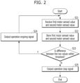
- FIG. 2 is a flowchart of a process of operation of the safety controller and peripheral components of FIG. 1 .
- FIG. 1 illustrates that the safety controller is provided on a traveling robot
- the application is not necessarily limited to traveling robots.
- the safety controller may be applied even to non-traveling robots (e.g., industrial assembly robots).
- a robot 100 may include a path guider 1000, a drive unit 2000, a motor driver 3000, an actuator assembly 4000, a traveling safety sensor 5000, and a safety controller 6000.
- the path guider 1000 may generate a travel path, such as a global path or a local path, for the robot 100 to travel and provide the same to the drive unit 2000.
- the path guider 1000 may utilize pre-stored map information and/or utilize map-related information and/or travel path-related information received from a control server (not shown).
- the drive unit 2000 may drive the actuator assembly 4000 via the motor driver 3000 to enable the robot to operate along the travel path received from the path guider 1000.
- the motor driver 3000 may convert an output signal from the drive unit 2000 into a drive signal and provide the drive signal to the actuator assembly 4000.
- One or more of the actuator assemblies 4000 may be provided in the robot 100, depending on the form and/or function of the robot 100. While one actuator assembly 4000 will be primarily described herein, the description can be applied to another actuator assembly 4000 provided in the robot 100.
- the actuator assembly 4000 may include a motor 4100, a motor drive body 4200, a first motor sensor 4310, and a second motor sensor 4320.
- the motor 4100 may rotate to move the motor drive body 4200 in response to a drive signal received from the motor driver 3000.
- the motor drive body 4200 may be a wheel.
- the wheels 4200 may be driven, that is, rotated, and thus the robot 100 may travel.
- a plurality of motor sensors for sensing the rotational motion of the motor 4100 may be provided in the actuator assembly 4000. While FIG. 1 illustrates two motor sensors per motor, namely a first motor sensor 4310 and a second motor sensor 4320, it is to be understood that more motor sensors may be provided.
- the first motor sensor 4310 and the second motor sensor 4320 may each sense rotational motion of the motor 4100 independently of each other to acquire rotation data, such as a rotational position and/or a rotational speed.
- the first motor sensor 4310 and the second motor sensor 4320 may sense rotational motion at different resolutions.
- the first motor sensor 4310 may be a high-resolution motor sensor and the second motor sensor 4320 may be a low-resolution motor sensor.
- the first motor sensor 4310 may be a high-resolution motor encoder and the second motor sensor 4320 may be a low-resolution motor encoder.
- the second motor sensor 4320 may be less expensive than the first motor sensor 4310.
- the second motor sensor 4320 may be a high-resolution motor sensor and the first motor sensor 4310 may be a low-resolution motor sensor.
- a motor encoder can be understood as a sensor that outputs multiple pulses per revolution (PPR) as the motor shaft makes one revolution.
- PPR pulses per revolution
- the PPR of a motor encoder being 100 means that the motor encoder outputs 100 pulses per revolution of the motor shaft. Therefore, as the PPR increases, the resolution at which the motor encoder can sense the rotational motion of the motor increases. In other words, the higher the PPR, the more expensive the motor encoder may be.
- an optical motor encoder may include a light emitting element (e.g., a light emitting diode (LED)) configured to emit light, a light receiving element (photo sensor) configured to receive the light, and a slit disk positioned between the light emitting element and the light receiving element.
- a light emitting element e.g., a light emitting diode (LED)
- a light receiving element photo sensor
- a slit disk positioned between the light emitting element and the light receiving element.
- the second motor sensor 4320 may be implemented as another low-cost, low-resolution sensor (e.g., a Hall sensor) rather than the motor encoder as a sensor to sense the rotation of the motor.
- the first motor sensor 4310 may be configured as a motor encoder of either high or low resolution
- the second motor sensor 4320 may be configured as a Hall sensor of lower resolution.
- the sensed value of the first motor sensor i.e., first rotation data
- the sensed value of the second motor sensor i.e., second rotation data
- the sensed value of the first motor sensor 4310 and the second motor sensor 4320, respectively, may be provided to the safety controller 6000 [S21].
- the safety controller 6000 may temporarily store the sensed value of the first motor sensor and the sensed value of the second motor sensor [S22]. This is for comparison of the sensed value of the first motor sensor and the sensed value of the second motor sensor, which will be described below, and may be omitted.
- the sensed value of the first motor sensor and the sensed value of the second motor sensor may be referred to as a first motor sensed value (or first motor value) and a second motor sensed value (or second motor value), respectively.
- the safety controller 6000 may determine whether the difference between the first motor sensed value and the second motor sensed value is within a preset threshold [S23]. That is, the safety controller 6000 may calculate a first rotational speed of the motor 4100 based on the first rotation data and a second rotational speed of the motor 4100 based on the second rotation data, and determine whether the difference between the first rotational speed and the second rotational speed is within the preset threshold [S23].
- the safety controller 6000 may determine that both the first motor sensor 4310 and the second motor sensor 4320 are operating normally, and may output an operation ongoing signal [S24]. Then, the motor driver 3000 may be caused to continue driving the motor 4100 according to the operation ongoing signal.
- the safety controller 6000 may determine that at least one of the first motor sensor 4310 and the second motor sensor 4320 is operating abnormally, and may output an operation stop signal to the motor driver 3000 [S25]. Then, the motor driver 3000 may stop driving the motor 4100 and/or cut off the power supplied to the motor 4100 in response to the operation stop signal. Thus, the robot 100 may stop traveling.
- the operation stop signal may correspond to a safety stop (SS) signal input to the motor driver 3000 to stop driving the motor 4100 (to slow down the rotational speed of the motor 4100).
- the operation stop signal may correspond to a safety torque off (STO) signal that is input to the motor driver 3000 to cut off the power supplied to the motor and/or to stop the motor from generating torque.
- SS safety stop
- STO safety torque off
- the safety controller 6000 may receive various sensing signals related to traveling safety from the traveling safety sensor 5000.
- the traveling safety sensor 5000 may be intended to prevent collisions between the robot 100 and external objects, for example, during traveling, and may include at least one of a LiDAR sensor, a vision sensor (e.g., a camera), or a depth sensor to sense external objects.
- the safety controller 6000 may analyze the sensing signals related to traveling safety and output an operation stop signal to the motor driver 3000 upon determining that traveling safety is at risk (e.g., a collision with an external object is expected).
- the motor driver 3000 may then stop driving the motor 4100 and/or cut off the power supplied to the motor 4100 in response to the operation stop signal.
- the robot 100 may stop traveling and prevent a collision.
- FIG. 3 is a perspective view of an actuator assembly that may be provided in a robot according to one aspect of the present disclosure.
- a decelerator 4400 configured to decelerate the wheels 4200 may be provided between one side of the motor 4100 and the motor drive body 4200.
- a first motor encoder and a second motor encoder as the first motor sensor 4310 and the second motor sensor 4320, may be provided on the rotation shaft of the motor 4100 on the opposite side of the motor 4100 so as to be arranged side by side along the longitudinal direction of the rotation axis X in an overlapping manner.
- a pair of actuator assemblies 4000 may be provided side by side in the direction of the rotation axis X.
- the actuator assembly 4000 is bound to be bulky.
- the distance between the two wheels may increase in proportion to the length of the first motor encoder 4310 and the second motor encoder 4320, and thus the width of the traveling robot 100 may increase accordingly.
- the first motor encoder 4310 and the second motor encoder 4320 are expensive parts, regardless of their resolution.
- FIG. 4 is a cross-sectional view and exploded view of a motor according to one aspect of the present disclosure.
- FIG. 5 is a block diagram of a variation of the actuator assembly of FIG. 1 .
- a motor 4100 may include a rotor 4110 composed of a permanent magnet, a stator 4120 (or 4120-1 to 4120-3) composed of coil windings, and at least one Hall sensor 4130 (or 4130-1 to 4130-3) configured to sense rotation of the motor shaft.
- the Hall sensor 4130 of the motor 4100 may be used as the second motor sensor 4320.
- the previously described motor encoder may still be used as the first motor sensor 4310, while the Hall sensor 4130 of the motor 4100 may be used as the second motor sensor 4320.
- the actuator assembly configured in this manner may be less bulky than the actuator assembly of FIG. 1 .
- the first sensed value (i.e., first rotation data) and the second sensed value (i.e., second rotation data) sensed by the motor encoder 4310 and the Hall sensor 4320, respectively, may be provided to the safety controller 6000.
- the safety controller 6000 may determine whether the difference between the first sensed value and the second sensed value is within a preset threshold. For example, the safety controller 6000 may calculate a first rotational speed of the motor 4100 based on the first sensed value and a second rotational speed of the motor 4100 based on the second sensed value, and determine whether the difference between the first rotational speed and the second rotational speed is within a preset threshold.
- the safety controller 6000 may determine that both the first motor sensor 4310 and the second motor sensor 4320 are operating normally, and may output an operation ongoing signal.
- the motor driver 3000 may then cause the motor driver 3000 to continue to drive the motor 4100 according to the operation ongoing signal.
- the safety controller 6000 may determine that at least one of the first motor sensor 4310 and the second motor sensor 4320 is operating abnormally, and may output an operation stop signal to the motor driver 3000. Then, the motor driver 3000 may stop driving the motor 4100 and/or cut off the power supplied to the motor 4100 in response to the operation stop signal. Thus, the robot 100 may stop traveling.
- FIG. 6 is a perspective view of an actuator assembly that may be provided to a robot according to one aspect of the present disclosure.
- a decelerator 4400 configured to decelerate the wheels 4200 may be provided between one side of the motor 4100 and the motor drive body 4200.
- a first motor encoder may be provided as the first motor sensor 4310 on the rotation shaft of the motor 4100 on the opposite side of the motor 4100 so as to be arranged along the longitudinal direction of the rotation axis X in an overlapping manner.
- the Hall sensor 4130 in the motor 4100 may be used as the second motor sensor 4320.
- a pair of actuator assemblies 4000 may be provided side by side in the direction of the rotation axis X.
- only one motor encoder 4310 is provided for each actuator assembly in the longitudinal direction of the rotation axis X.
- the distance between the two wheels may be reduced, and the width of the traveling robot 100 may be reduced accordingly.
- only one motor encoder 4310 is used for each actuator assembly, which may result in a lower manufacturing cost.
- FIG. 7 illustrates an example of a first motor sensing signal, a second motor sensing signal, and an operation signal according to one aspect of the present disclosure.
- the Hall sensor 4320 may output a step signal in which a plurality of steps (or levels) (S1, S2, S3, ..., SN) is repeated per 360 degree rotation of the motor 4100.
- the number and shape of the plurality of steps may be determined by the number and arrangement of Hall sensors in the motor. For example, when three Hall sensors are provided in the motor, the signal may have a total of six steps.
- a step change in the step signal at a predetermined time interval first to second time interval (T1 to T2), second to third time interval (T2 to T3), ...) may mean that the Hall sensor 4320 senses the motor 4100 rotating at a predetermined speed. When the predetermined time interval is long, the motor 4100 may be rotating at a low speed.
- the motor 4100 When the predetermined time interval is short, the motor 4100 may be rotating at a high speed. When the predetermined time interval remains constant, the motor 4100 may be rotating at a constant speed. When the predetermined time interval gets longer and longer, it may mean that the motor 4100 may be gradually slowing down. When the predetermined time interval gets shorter and shorter, it may mean that the motor 4100 may be gradually speeding up.
- the rotational speed may be calculated by sensing changes in their signals.
- the Hall sensor changes are divided into six steps, and the (radian) distance corresponding to the first step may be calculated, and the time (sec) traveled, for example, may be measured using the interrupt and timer functions inside the safety controller.
- Hall sensor speed (radian/sec) [Step 1 * 2PI (radian)] / [Step 6 * Number of pole pairs * Gear ratio * Step 1 travel time (sec)]
- the motor encoder 4310 may output a pulse signal having a pulse interval that is inversely proportional to the rotational speed of the motor 4100.
- a longer pulse interval may indicate that the motor 4100 is rotating at a lower speed, and a shorter pulse interval may indicate that the motor 4100 is rotating at a higher speed.
- the pulse interval remains constant, the motor 4100 may rotate at a constant speed.
- the pulse interval becomes longer, the motor 4100 may rotate at a lower speed.
- the pulse interval becomes shorter the motor 4100 may rotate at a higher speed.
- the number of pulses generated per 360-degree rotation of the motor 4100 may depend on the resolution of the motor encoder 4310. In other words, the number of pulses generated per 360-degree rotation of the motor 4100 may be proportional to the resolution of the motor encoder 4310.
- the speed may be calculated by determining the change in the count of the motor encoder at regular intervals.
- An example equation for calculating the rotational speed of the motor using the motor encoder is shown below.
- Encoder speed (radian/sec) [Encoder count change value * 2PI (radian)] / [Encoder count value per revolution * gear ratio * period (sec)]
- both the output signal of the Hall sensor 4310 and the output signal of the motor encoder 4320 between the first time T1 and the fourth time point T4 correspond to the first speed (i.e., the same speed) of the motor 4100.
- the safety controller 6000 may output a high-level signal to the motor driver 3000.
- the high-level signal indicates that both the motor encoder 4310 and the Hall sensor 4320 are operating normally, which may correspond to the operation ongoing signal described above.
- the motor driver 3000 may continue to drive the motor 4100.
- the output signal of the Hall sensor 4310 corresponds to the first speed of the motor 4100
- the output signal of the motor encoder 4320 corresponds to the second speed of the motor 4100, which may mean that the output signals correspond to different speeds. Assume that the difference between the first speed and the second speed is above a threshold.
- the safety controller 6000 may output a low-level signal to the motor driver 3000.
- the low-level signal may indicate that at least one of the motor encoder 4310 and the Hall sensor 4320 is operating abnormally. That is, the low-level signal may correspond to the operation stop signal described above. Accordingly, the motor driver 3000 may continue to drive the motor 4100. In response to the low-level signal, the motor driver 3000 may stop driving the motor 4100 and/or cut off the power supplied to the motor 4100. Thus, the robot 100 may stop traveling.
- the high-level operation ongoing signal and the low-level operation stop signal may be for implementing a safety torque off (STO) function of the motor.
- STO safety torque off
- the aforementioned operation ongoing signal and operation stop signal are not limited to the high-level signal and the low-level signal, respectively.
- the operation ongoing signal and the operation stop signal may be a low-level signal and a high-level signal, respectively.
- the operation ongoing signal and the operation stop signal may each be configured as a signal of another waveform.
- FIG. 8 illustrates one example of the safety controller of FIG. 1 .
- the safety controller 6000 may include a speed monitor 6100.
- the speed monitor 6100 may receive a first motor sensed value input from the first motor sensor 4310 and a second motor sensed value input from the second motor sensor 4320.
- the speed monitor 6100 may compare the first motor sensed value with the second motor sensed value and output an operation signal, such as an operation ongoing signal or an operation stop signal, to the motor driver 3000.
- an operation signal such as an operation ongoing signal or an operation stop signal
- FIG. 9 illustrates one example of the safety controller of FIG. 1 .
- the safety controller 6000 may include a speed monitor 6100, which includes a first speed sub-monitor 6110 and a second speed sub-monitor 6120.
- the first motor sensed value of the first motor sensor 4310 may be input to the first speed sub-monitor 6110, and the second motor sensed value of the second motor sensor 4320 may be input to the second speed sub-monitor 6120.
- the first speed sub-monitor 6110 may compute a first rotational speed of the first motor sensor 4310 based on the first motor sensed value
- the second speed sub-monitor 6120 may compute a second rotational speed of the second motor sensor 4320 based on the second motor sensed value.
- the first speed sub-monitor 6110 may provide the first motor sensed value or first rotational speed to the second speed sub-monitor 6120, and the second speed sub-monitor 6120 may provide the second motor sensed value or second rotational speed to the first speed sub-monitor 6110.
- the second speed sub-monitor 6120 When the second speed sub-monitor 6120 receives the first motor sensed value from the first speed sub-monitor 6110, it may compute the first rotational speed based on the received value.
- the first speed sub-monitor 6110 receives the second motor sensed value from the second speed sub-monitor 6120, it may compute the second rotational speed based on the received value.
- the first speed sub-monitor 6110 may output a first operation signal, that is, a first operation ongoing signal or a first operation stop signal.
- the first operation signal namely, the first operation ongoing signal and the first operation stop signal, may not be directly output to the motor driver 3000. Therefore, the first operation signals (i.e., the first operation ongoing signal and the first operation stop signal) may be referred to as first operation sub-signals (the first operation ongoing sub-signal and the first operation stop sub-signal) to distinguish them from the operation signals (i.e., the operation ongoing signal and the operation stop signal) that are output to the motor driver 3000 as described above.
- the second speed sub-monitor 6120 may also output a second operation signal, such as a second operation ongoing signal or a second operation stop signal, based on the first rotational speed and the second rotational speed.
- the second operation signal namely, the second operation ongoing signal and the second operation stop signal, may not be directly output to the motor driver 3000. Therefore, the second operation signals (the second operation ongoing signal and the second operation stop signal) may be referred to as second operation sub-signals (the second operation ongoing sub-signal and the second operation stop sub-signal) to distinguish them from the operation signals (the operation ongoing signal and the operation stop signal) output to the motor driver 3000 described above.
- the same process for generating the operation signal as described above may be used.
- the first speed sub-monitor 6110 and the second speed sub-monitor 6120 may output operation signals based on the first rotation speed and the second rotation speed independently of each other. In other words, the first speed sub-monitor 6110 and the second speed sub-monitor 6120 may perform monitoring that compares the first motor sensed value and the second motor sensed value.
- first operation ongoing signal and the second operation ongoing signal are high-level signals
- first operation stop signal and the second operation stop signal are low-level signals
- the first operation signal and the second operation signal may be input to the AND gate 6130.
- the AND gate 6130 may be provided in the speed monitor 6100, or may be provided outside of the speed monitor 6100.
- the AND gate 6130 When both the first operation signal and the second operation signal are operation ongoing signals (i.e., the first operation signal is the first operation ongoing signal and the second operation signal is the second operation ongoing signal), the AND gate 6130 outputs an operation ongoing signal (i.e., a high-level signal). When at least one of the first operation signal and the second operation signal is an operation stop signal (i.e., the first operation signal is the first operation stop signal and/or the second operation signal is the second operation stop signal), the AND gate 6130 outputs an operation stop signal (i.e., a low-level signal). The output signal of the AND gate 6130 is provided to the motor driver 3000.
- FIG. 10 illustrates one example of the safety controller of FIG. 1 .
- the safety controller 6000 may include a speed monitor 6100, which includes a first speed sub-monitor 6110 and a second speed sub-monitor 6120.
- a first motor sensed value from the first motor sensor 4310 may be branched and input to the first speed sub-monitor 6110 and the second speed sub-monitor 6120, respectively, and a second motor sensed value from the second motor sensor 4320 may be branched and input to the first speed sub-monitor 6110 and the second speed sub-monitor 6120, respectively.
- the first speed sub-monitor 6110 may compute a first rotational speed and a second rotational speed based on the first motor sensed value and the second motor sensed value
- the second speed sub-monitor 6120 may also compute a first rotational speed and a second rotational speed based on the first motor sensed value and the second motor sensed value.
- the first speed sub-monitor 6110 may output a first operation signal, namely a first operation ongoing signal or a first operation stop signal, based on the first rotational speed and the second rotational speed.
- the second speed sub-monitor 6120 may output a second operation signal, namely a second operation ongoing signal or a second operation stop signal, based on the first rotational speed and the second rotational speed.
- the first speed sub-monitor 6110 and the second speed sub-monitor 6120 may output operation signals based on the first rotation speed and the second rotation speed independently of each other. In other words, the first speed sub-monitor 6110 and the second speed sub-monitor 6120 may perform monitoring that compares the first motor sensed value and the second motor sensed value.
- first operation ongoing signal and the second operation ongoing signal are high-level signals
- first operation stop signal and the second operation stop signal are low-level signals
- the first operation signal and the second operation signal may be input to the AND gate 6130.
- the AND gate 6130 may be provided in the speed monitor 6100, or may be provided outside of the speed monitor 6100.
- the AND gate 6130 When both the first operation signal and the second operation signal are operation ongoing signals (i.e., the first operation signal is the first operation ongoing signal and the second operation signal is the second operation ongoing signal), the AND gate 6130 outputs an operation ongoing signal (i.e., a high-level signal). When at least one of the first operation signal and the second operation signal is an operation stop signal (i.e., the first operation signal is the first operation stop signal and/or the second operation signal is the second operation stop signal), the AND gate 6130 outputs an operation stop signal (i.e., a low-level signal). The output signal of the AND gate 6130 is provided to the motor driver 3000.
- the speed monitor 6100 may be used for two or more motors (i.e., two or more actuator assemblies).
- the two or more motors may be for each of two or more wheels mounted on the traveling robot 100. This is discussed further with reference to FIG. 11.
- FIG. 11 is a block diagram of a plurality of actuator assemblies, which is a variation of the actuator assembly of FIG. 5 .
- the motor driver 3000 may operate for two or more actuator assemblies. Specifically, the motor driver 3000 may convert an output signal for a first actuator assembly of the drive unit 2000 into a drive signal and provide the drive signal to a first actuator assembly 4000-1, and convert an output signal for a second actuator assembly of the drive unit 2000 into a drive signal and provide the drive signal to a second actuator assembly 4000-2.
- While the motor driver 3000 is illustrated in FIG. 11 as operating for the first actuator assembly 4000-1 and the second actuator assembly 4000-2, it may operate for more actuator assemblies.
- the first actuator assembly 4000-1 may be used for a traveling wheel on one side of the traveling robot 100
- the second actuator assembly 4000-2 may be used for a traveling wheel on the opposite side of the traveling robot 100.
- the first actuator assembly 4000-1 may include a first motor 4100-1, a 1-1-th motor sensor 4310-1, a 1-2-th motor sensor 4320-1, and a first motor drive body 4200-1. While the 1-2-th motor sensor 4320-1 is illustrated as being configured as a Hall sensor in the first motor 4100-1, it may be configured as a motor encoder separate from the first motor 4100-1. The 1-1-th motor sensor 4310-1 and the 1-2-th motor sensor 4320-1 may correspond to the first motor sensor 4310 and the second motor sensor 4320 described above for the first motor 4100-1, respectively.
- a 1-1-th motor sensed value i.e., 1-1-th rotation data
- a 1-2-th motor sensed value i.e., 1-2-th rotation data
- the 1-1-th motor sensed value and the 1-2-th motor sensed value may correspond to the first motor sensed value and the second motor sensed value described above for the first motor 4100-1, respectively.
- the second actuator assembly 4000-2 may include a second motor 4100-2, a 2-1-th motor sensor 4310-2, a 2-2-th motor sensor 4320-2, and a second motor drive body 4200-2. While the 2-2-th motor sensor 4320-2 is illustrated as being configured as a Hall sensor in the second motor 4100-2, it may be configured as a motor encoder separate from the second motor 4100-2. The 2-1-th motor sensor 4310-2 and the 2-2-th motor sensor 4320-2 may correspond to the first motor sensor 4310 and the second motor sensor 4320 described above for the second motor 4100-2, respectively.
- the 2-1-th motor sensed value (i.e., 2-1-th rotation data) and the 2-2-th motor sensed value (i.e., 2-2-th rotation data) sensed by the 2-1-th motor sensor 4310-2 and the 2-2-th motor sensor 4320-2, respectively, may be provided to the safety controller 6000.
- the 2-1-th motor sensed value and the 2-2-th motor sensed value may correspond to the first motor sensed value and the second motor sensed value described above for the second motor 4100-2, respectively.
- FIG. 12 illustrates an example of a safety controller for the plurality of actuator assemblies of FIG. 11 .
- the 1-1-th motor sensed value of the 1-1-th motor sensor 4310-1 may be branched and input to the first speed sub-monitor 6110 and the second speed sub-monitor 6120, respectively, and the 1-2-th motor sensed value of the 1-2-th motor sensor 4320-1 may be branched and input to the first speed sub-monitor 6110 and the second speed sub-monitor 6120, respectively.
- the 2-1-th motor sensed value of the 2-1-th motor sensor 4310-2 may be branched and input to the first speed sub-monitor 6110 and the second speed sub-monitor 6120, respectively, and the 2-2-th motor sensed value of the 2-2-th motor sensor 4320-2 may be branched and input to the first speed sub-monitor 6110 and the second speed sub-monitor 6120, respectively.
- the first speed sub-monitor 6110 may compute a 1-1-th rotational speed and a 1-2-th rotational speed of the first motor 4100-1 based on the 1-1-th motor sensed value and the 1-2-th motor sensed value
- the second speed sub-monitor 6120 may also compute a 1-1-th rotational speed and a 1-2-th rotational speed of the first motor 4100-1 based on the 1-1-th motor sensed value and the 1-2-th motor sensed value.
- the first speed sub-monitor 6110 may output a 1-1-th operation signal S1-1, namely a 1-1-th operation ongoing signal or a 1-1-th operation stop signal, based on the 1-1-th rotational speed and the 1-2-th rotational speed.
- the 1-1-th operation signal S1-1 may correspond to the aforementioned first operation sub-signal attributed to the first motor.
- the 1-1-th operation signal S1-1 namely the 1-1-th operation ongoing signal and the 1-1-th operation stop signal, may not be directly output to the motor driver 3000.
- the 1-1-th operation signals i.e., the 1-1-th operation ongoing signal and 1-1-th operation stop signal
- 1-1-th operation sub-signals (1-1-th operation ongoing sub-signal and 1-1-th operation stop sub-signal) to distinguish them from the operation signals (operation ongoing signal and operation stop signal) output to the motor driver 3000 described above.
- the second speed sub-monitor 6120 may output a 1-2-th operation signal S1-2, namely a 1-2-th operation ongoing signal or a 1-2-th operation stop signal, based on the 1-1-th rotational speed and the 1-2-th rotational speed.
- the 1-2-th operation signal S 1-2 may correspond to the aforementioned second operation sub-signal attributed to the first motor.
- the 1-2-th operation signals S1-2 namely the 1-2-th operation ongoing signal and the 1-2-th operation stop signal, may not be directly output to the motor driver 3000.
- the 1-2-th operation signals i.e., the 1-2-th operation ongoing signal and 1-2-th operation stop signal
- 1-2-th operation sub-signals 1-2-th operation ongoing sub-signal and 1-2-th operation stop sub-signal
- the second speed sub-monitor 6120 may compute a 2-1-th rotational speed and a 2-2-th rotational speed of the second motor 4100-2 based on the 2-1-th motor sensed value and the 2-2-th motor sensed value, and the first speed sub-monitor 6110 may also compute a 2-1-th rotational speed and a 2-2-th rotational speed of the second motor 4100-2 based on the 2-1-th motor sensed value and the 2-2-th motor sensed value.
- the first speed sub-monitor 6110 may output a 2-1-th operation signal S2-1, namely a 2-1-th operation ongoing signal or a 2-1-th operation stop signal, based on the 2-1-th rotational speed and the 2-2-th rotational speed.
- the 2-1-th operation signal S2-1 may correspond to the aforementioned first operation sub-signal attributed to the second motor.
- the 2-1-th operation signal S2-1 namely the 2-1-th operation ongoing signal and the 2-1-th operation stop signal, may not be directly output to the motor driver 3000.
- the 2-1-th operation signals i.e., the 2-1-th operation ongoing signal and 2-1-th operation stop signal
- 2-1-th operation sub-signals 2-1-th operation ongoing sub-signal and 2-1-th operation stop sub-signal
- the second speed sub-monitor 6120 may output a 2-2-th operation signal S2-2, namely a 2-2-th operation ongoing signal or a 2-2-th operation stop signal, based on the 2-1-th rotational speed and the 2-2-th rotational speed.
- the 2-2-th operation signal S2-2 may correspond to the aforementioned second operation sub-signal attributed to the second motor.
- the 2-2-th operation signals S2-2 namely the 2-2-th operation ongoing signal and the 2-2-th operation stop signal, may not be directly output to the motor driver 3000.
- the 2-2-th operation signals i.e., 2-2-th operation ongoing signal and 2-2-th operation stop signal
- 2-2-th operation sub-signals 2-2-th operation ongoing sub-signal and 2-2-th operation stop sub-signal
- the operation ongoing signal or operation stop signal is generated by comparing two independently sensed motor values for one motor, as described above.
- the 1-1-th operation ongoing signal, 1-2-th operation ongoing signal, 2-1-th operation ongoing signal, and 2-2-th operation ongoing signal are high-level signals
- the 1-1-th operation stop signal, 1-2-th operation stop signal, 2-1-th operation stop signal, and 2-2-th operation stop signal are low-level signals.
- the 1-1-th operation signal, the 1-2-th operation signal, the 2-1-th operation signal, and the 2-2-th operation signal may be input to the AND gate 6130.
- the AND gate 6130 may be provided in the speed monitor 6100, or may be provided outside of the speed monitor 6100.
- the AND gate 6130 When the 1-1-th operation signal, the 1-2-th operation signal, the 2-1-th operation signal, and the 2-2-th operation signal are all operation ongoing signals, the AND gate 6130 will output an operation ongoing signal (i.e., a high-level signal). When at least one of the 1-1-th operation signal, the 1-2-th operation signal, the 2-1-th operation signal, and the 2-2-th operation signal is an operation stop signal, the AND gate 6130 will output an operation stop signal (i.e., a low-level signal). The output signal of the AND gate 6130 is provided to the motor driver 3000.
- the motor driver 3000 When the motor driver 3000 receives the operation ongoing signal, it may cause the first motor 4100-1 and the second motor 4100-2 to continue driving. However, when the motor driver 3000 receives the operation stop signal, it may stop driving the first motor 4100-1 and the second motor 4100-2 or cut off the power supplied to the first motor 4100-1 and the second motor 4100-2. Thus, the robot 100 may stop traveling.
- an OR gate may be used instead of the AND gate.
- the OR gate may output the operation stop signal.
- the OR gate may output the operation ongoing signal.
- the speed monitor 6100 includes an AND gate or an OR gate.
- the AND gate or OR gate may not necessarily be included in the speed monitor 6100. This will be further described with reference to FIG. 13.
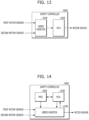
- FIG. 13 illustrates an example of the safety controller of FIG. 1 .
- the safety controller 6000 may include a speed monitor 6100 and a processor 6200.
- the safety controller 6000 may be implemented as a single board and mounted on the robot 100.
- the speed monitor 6100 may be the same as the speed monitors described above with reference to FIGS. 9, 10 , and 12 , except that it does not include an AND gate or an OR gate.
- the processor 6200 may be configured as a microcontroller unit.
- the speed monitor 6100 may receive a first motor sensed value and a second motor sensed value from the first motor sensor 4310 and the second motor sensor 4320 described above, and may generate a first operation signal and a second operation signal based on the received sensed values.
- the speed monitor 6100 may provide the first motor sensed value (or first rotational speed), the second motor sensed value (or second rotational speed), the first operation signal, and the second operation signal to the processor 6200.
- the processor 6200 may again verify the correctness of the first operation signal and/or the second operation signal. For example, even if the first operation signal and the second operation signal are the first operation ongoing signal and the second operation ongoing signal, the processor 6200 may once again verify that they are the first operation ongoing signal and the second operation ongoing signal based on whether the difference between the first motor sensed value (or first rotational speed) and the second motor sensed value (or second rotational speed) is within a threshold.
- an operation stop signal may be output despite the first operation ongoing signal and the second operation ongoing signal received from the speed monitor 6100.
- the processor 6200 may further consider a target speed (or target travel speed) of the traveling robot 100 to verify the correctness of the operation signals.
- target speed may refer to a currently required (or intended) travel speed of the traveling robot 100.
- the target speed may be received by the processor 6200 from the path guider 1000.
- an operation ongoing signal is output when the difference between the first motor sensed value and the second motor sensed value is within a threshold, and an operation stop signal is output when the difference is beyond the threshold.
- the processor 6200 may output an operation stop signal if the travel speed of the robot 1000 according to at least one of the first motor sensed value and the second motor sensed value is beyond the target speed and a predetermined range, even if both the first operation sub-signal and the second operation sub-signal correspond to operation ongoing signals. This is because even if the difference between the first motor sensed value and the second motor sensed value is within the threshold, both sensed values may be viewed as having an error or the motor 4100 or other components may be viewed as having an error.
- the processor 6200 may output the operation ongoing signal if the travel speed of the robot 1000 according to the first motor sensed value and the second motor sensed value is within the target speed and the predetermined range.
- the operation signal output by the processor 6200 may be provided to the motor driver 3000.
- the motor driver 3000 may operate in response to the operation signal as described above.
- the speed monitor 6100 of FIG. 13 includes an AND gate or an OR gate.
- the speed monitor 6100 may also include an AND gate or an OR gate.
- the output signal of the AND gate or OR gate may be provided to the processor 6200, and the processor 6200 may verify the output signal based on the target speed as well as the first motor sensed value and the second motor sensed value.
- FIG. 14 illustrates an example of the safety controller of FIG. 1 .
- the safety controller may include a power manager 6300 as well as the speed monitor 6100 and processor 6200.
- the safety controller 6000 may be implemented as a single board and mounted on the robot 100.
- An operation signal output from the speed monitor 6100 may be provided to the motor driver 3000.
- the data or signals provided to the processor 6200 from the speed monitor 6100 may be the same as described with reference to FIG. 13 .
- the processor 6200 may once again verify the correctness of the operation signal based on the first motor sensed value, the second motor sensed value, and the target speed, as described with reference to FIG. 13 .
- the processor 6200 may output a control signal to the speed monitor 6100 to cause the speed monitor 6100 to continue to output the operation signal (operation ongoing signal or operation stop signal) to the motor driver 3000.
- the processor 6200 may output a control signal to the speed monitor 6100 to cause the speed monitor 6100 to output an operation stop signal to the motor driver 3000.
- the processor 6200 may output a control signal to the speed monitor 6100 to cause the speed monitor 6100 to output an operation stop signal to the motor driver 3000, or may output a control signal to the speed monitor 6100 to cause the speed monitor 6100 to output an operation ongoing signal to the motor driver 3000.
- whether to output the operation ongoing signal or the operation stop signal may be determined by a preset.
- the power manager 6300 may manage the power usage of the processor 6200 and monitor the power usage of the processor 6200 for abnormalities.
- the power manager may output a control signal to the speed monitor 6100 to cause the speed monitor 6100 to output an operation stop signal to the motor driver 3000.
- the speed monitor 6100 may output the operation stop signal to the motor driver 3000 according to the control signal for the operation stop signal received from the power manager.
- connection harness may be simplified.
- the safety controller 6000 may continue to execute the process of FIG. 2 while the robot 100 is traveling. In addition, the safety controller 6000 may perform the following travel safety-related operation process in parallel with the operation process of FIG. 2 . This will be described with further reference to FIG. 15.
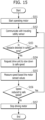
- FIG. 15 is a flowchart illustrating another process of operation of the safety controller of FIG. 2 and peripheral components thereof.
- the motor driver 3000 may convert an output signal of the drive unit 2000 into an operation signal to start operating the motor and provide the operation signal to the actuator assembly 4000, that is, the motor 4100 [S151],
- the safety controller 5000 may perform the operation process of FIG. 2 described above.
- the safety controller 5000 may communicate with the traveling safety sensor 5000 separately from the operation process of FIG. 2 [S152]. That is, the safety controller 5000 may receive a traveling safety sensing signal from the traveling safety sensor 5000.
- the safety controller 5000 may determine whether there is an obstacle within a safety zone [S 153].
- the safety zone may refer to an area around the robot 100 that should be free of obstacles for safe traveling of the robot 100.
- the size of the safety zone may be variable in proportion to the traveling speed or target speed of the robot 100.
- the safety controller 5000 may continue to communicate with the safety sensor and allow the robot to continue traveling.
- the safety controller 5000 may output a control signal requesting the drive unit 2000 to slow down to a safe speed [S154].
- the safety controller 5000 may measure the traveling speed of the robot 1000 based on the motor sensed values described above [S 155].
- the safety controller 5000 may determine whether the traveling speed of the robot 1000 has been reduced to a safe speed within a predetermined time [S156].
- the predetermined time may be varied to be proportional to the difference between the traveling speed and the safe speed.
- the safety controller 5000 may continue to communicate with the safety sensor and allow the robot to continue traveling.
- the safety controller 5000 may output an operation stop signal to the motor driver 3000. That is, when the traveling speed has not been reduced to the safe speed, the safety controller 5000 may output an operation stop signal to the motor driver 3000 even if the difference between the first motor sensed value and the second motor sensed value of the motor 4100 is within a threshold.
- the motor driver 3000 receives the operation stop signal, it may stop driving the motor 4100 or cut off the power supplied to the motor 4100 [S 157]. Thus, the robot 100 may stop traveling.
- FIG. 16 is a graph depicting an operation stop signal input to the motor driver 3000 to stop traveling of the robot according to one aspect of the present disclosure.
- V represents a traveling speed of the robot.
- Graph 16-1 in FIG. 16 illustrates that the operation stop signal consists of an STO signal only.
- an operation stop signal may be input to the motor driver 3000 when an abnormality of the motor 4100, motor sensors 4310, 4320, or other components is detected at a first time A while the robot 100 is traveling at speed V.
- the motor driver 3000 may cut off power to the motor 4100. That is, the motor driver 3000 may prevent the motor 4100 from generating torque. Then, the robot 100 may move and stop based on inertia as the speed decreases.
- Graph 16-2 in FIG. 16 illustrates that the operation stop signal consists of an SS signal and an STO signal. That is, when an abnormality of the motor 4100, motor sensors 4310, 4320, or other components is detected at the first time A while the robot 100 is traveling at speed V, an SS signal may be input to the motor driver 3000 after a first time period t1. The SS signal may be input during a second time period t2 until the robot decelerates to a target stop speed (e.g., 0 m/s). After the second time period t2, the STO signal may be input to the motor driver 3000. The motor driver 3000 may then cut off the power supplied to the motor 4100. That is, the motor driver 3000 may prevent the motor 4100 from generating torque. Then, the robot 100 may stay stationary.
- a target stop speed e.g., 0 m/s
- the torque of the motor 4100 may not be generated and the robot 100 may travel at a higher speed down the ramp. This may lead to a greater accident.
- the operation stop signal may consist of an SS signal and a standstill signal. That is, when an abnormality of the motor 4100, motor sensors 4310, 4320, or other components is detected at the first time A while the robot 100 is traveling at speed V on the ramp, an SS signal may be input to the motor driver 3000 after the first time period t1. The SS signal may be input during the second time period t2 until the robot decelerates to a target stop speed (e.g., 0 m/s). After the second time period t2, the standstill signal may continue to be input to the motor driver 3000 to ensure that the motor continues to generate stopping torque. The standstill signal may be included in the operation stop signal instead of the STO signal only during traveling of the robot 100 on the ramp.
- a target stop speed e.g., 0 m/s
- Various embodiments may be implemented using a machine-readable medium having instructions stored thereon for execution by a processor to perform various methods presented herein.
- machine-readable mediums include HDD(Hard Disk Drive), SSD(Solid State Disk), SDD(Silicon Disk Drive), ROM, RAM, CD-ROM, a magnetic tape, a floppy disk, an optical data storage device, the other types of storage mediums presented herein, and combinations thereof.
- the machine-readable medium may be realized in the form of a carrier wave (for example, a transmission over the Internet).
Landscapes
- Engineering & Computer Science (AREA)
- Power Engineering (AREA)
- Microelectronics & Electronic Packaging (AREA)
- Mechanical Engineering (AREA)
- Robotics (AREA)
- Remote Sensing (AREA)
- Radar, Positioning & Navigation (AREA)
- Physics & Mathematics (AREA)
- General Physics & Mathematics (AREA)
- Automation & Control Theory (AREA)
- Aviation & Aerospace Engineering (AREA)
- Transportation (AREA)
- Control Of Electric Motors In General (AREA)
- Manipulator (AREA)
Applications Claiming Priority (1)
| Application Number | Priority Date | Filing Date | Title |
|---|---|---|---|
| KR1020230080545A KR102811280B1 (ko) | 2023-06-22 | 2023-06-22 | 모터 안전 제어 방법 및 이를 구현하는 로봇 |
Publications (2)
| Publication Number | Publication Date |
|---|---|
| EP4482017A2 true EP4482017A2 (de) | 2024-12-25 |
| EP4482017A3 EP4482017A3 (de) | 2025-06-18 |
Family
ID=90363495
Family Applications (1)
| Application Number | Title | Priority Date | Filing Date |
|---|---|---|---|
| EP24161983.2A Pending EP4482017A3 (de) | 2023-06-22 | 2024-03-07 | Motorsicherheitssteuerungsverfahren und roboter |
Country Status (3)
| Country | Link |
|---|---|
| US (1) | US20240429840A1 (de) |
| EP (1) | EP4482017A3 (de) |
| KR (2) | KR102811280B1 (de) |
Families Citing this family (1)
| Publication number | Priority date | Publication date | Assignee | Title |
|---|---|---|---|---|
| US20250370483A1 (en) * | 2024-05-31 | 2025-12-04 | Wing Aviation Llc | Motor Health Monitor |
Family Cites Families (16)
| Publication number | Priority date | Publication date | Assignee | Title |
|---|---|---|---|---|
| JP3114579B2 (ja) * | 1995-08-30 | 2000-12-04 | 松下電器産業株式会社 | 産業用ロボットおよびその制御装置 |
| EP1364453A1 (de) | 2001-02-08 | 2003-11-26 | Stridsberg Innovation AB | Hochzuverlässiges motorsystem |
| ES2330606B1 (es) * | 2008-06-10 | 2010-10-15 | Metro De Madrid, S.A | Sistema de control para puertas del ambito ferroviario y metodo de accionamiento basado en dicho sistema. |
| CN102132126B (zh) * | 2008-08-26 | 2015-04-08 | 株式会社尼康 | 编码器系统、信号处理方法 |
| KR20110032916A (ko) * | 2009-09-24 | 2011-03-30 | 삼성전자주식회사 | 모터 제어기용 단일전원을 이용한 전원 공급 장치 |
| JP5367623B2 (ja) * | 2010-03-15 | 2013-12-11 | オムロン株式会社 | サーボシステム、サーボモータ駆動装置、セーフティユニットおよびサーボシステムの制御方法 |
| JP5970880B2 (ja) * | 2012-03-15 | 2016-08-17 | オムロン株式会社 | 動力源の制御装置 |
| KR101952962B1 (ko) * | 2012-09-27 | 2019-02-27 | 현대모비스 주식회사 | 스마트부스터 시스템의 위치센서 이상 검출방법 |
| KR101646210B1 (ko) * | 2014-09-23 | 2016-08-05 | 국민대학교산학협력단 | 기능 안전성을 고려한 모터 제어 시스템 |
| JP6428817B2 (ja) * | 2017-03-22 | 2018-11-28 | 株式会社安川電機 | モータ制御システム、制御方法、エンコーダ及びモータ制御装置 |
| CN110998471A (zh) * | 2017-05-09 | 2020-04-10 | 云海智行股份有限公司 | 机器人运动控制系统及方法 |
| WO2019220719A1 (ja) * | 2018-05-16 | 2019-11-21 | パナソニックIpマネジメント株式会社 | エンコーダの異常検出方法、作動制御装置、ロボット及びロボットシステム |
| KR102176408B1 (ko) * | 2018-11-07 | 2020-11-09 | 주식회사 현대케피코 | Bldc 모터 제어 장치 및 방법 |
| JP6620380B1 (ja) * | 2019-02-12 | 2019-12-18 | 株式会社安川電機 | モータ制御システム |
| JP7608094B2 (ja) | 2020-09-11 | 2025-01-06 | 株式会社東芝 | 移動体、制御装置、監視装置、制御方法、及びプログラム |
| US12074552B2 (en) * | 2021-11-09 | 2024-08-27 | Nidec Motor Corporation | Dual encoder system for electric motor |
-
2023
- 2023-06-22 KR KR1020230080545A patent/KR102811280B1/ko active Active
-
2024
- 2024-02-28 US US18/590,657 patent/US20240429840A1/en active Pending
- 2024-03-07 EP EP24161983.2A patent/EP4482017A3/de active Pending
-
2025
- 2025-05-15 KR KR1020250063041A patent/KR20250073062A/ko active Pending
Also Published As
| Publication number | Publication date |
|---|---|
| KR20250073062A (ko) | 2025-05-27 |
| KR102811280B1 (ko) | 2025-05-22 |
| KR20240178555A (ko) | 2024-12-31 |
| EP4482017A3 (de) | 2025-06-18 |
| US20240429840A1 (en) | 2024-12-26 |
Similar Documents
| Publication | Publication Date | Title |
|---|---|---|
| EP3110002B1 (de) | Vorrichtung zur erkennung eines motordrehwinkels und elektrische servolenkvorrichtung | |
| CN102445920B (zh) | 用于驱动单元用的碰撞识别的方法 | |
| US8494729B2 (en) | Method to determine torque | |
| EP4482017A2 (de) | Motorsicherheitssteuerungsverfahren und roboter | |
| BRPI1100822A2 (pt) | servomecanismo, dispositivo de acionamento para o servomotor, unidade de seguranÇa e mÉtodo para controlar o servomecanismo | |
| US20170047877A1 (en) | Motor control method and system | |
| JP5958519B2 (ja) | 制御装置、および、これを用いたシフトバイワイヤシステム | |
| WO2013002251A1 (ja) | モータ駆動装置 | |
| JP2015111971A (ja) | 制御装置、および、これを用いたシフトバイワイヤシステム | |
| KR20070041603A (ko) | 인코더 고장 검출 시스템 및 방법 | |
| KR101901127B1 (ko) | 모터 고장 판단 장치 및 방법 | |
| JP2005531269A (ja) | 同期電動機の回転子の位置を測定する方法 | |
| JP6006069B2 (ja) | エンコーダおよびエンコーダの異常検出方法 | |
| JP6706072B2 (ja) | 走行装置 | |
| KR20170002759A (ko) | 홀센서 고장진단방법 | |
| US20240149702A1 (en) | Overspeed detection device | |
| JP6583124B2 (ja) | シフトレンジ制御装置 | |
| KR20220093614A (ko) | 모터 위치 검출 장치 | |
| US7460030B2 (en) | System and method for encoder failure detection | |
| JP2017099130A (ja) | 電力変換装置 | |
| CN103109451A (zh) | 电动机驱动装置 | |
| JP2012070495A (ja) | モータ駆動制御装置 | |
| JP2008289361A (ja) | モータ駆動装置 | |
| JPH0344323B2 (de) | ||
| KR102505813B1 (ko) | 모터 전기각 보정 방법 및 장치 |
Legal Events
| Date | Code | Title | Description |
|---|---|---|---|
| PUAI | Public reference made under article 153(3) epc to a published international application that has entered the european phase |
Free format text: ORIGINAL CODE: 0009012 |
|
| STAA | Information on the status of an ep patent application or granted ep patent |
Free format text: STATUS: REQUEST FOR EXAMINATION WAS MADE |
|
| 17P | Request for examination filed |
Effective date: 20240328 |
|
| AK | Designated contracting states |
Kind code of ref document: A2 Designated state(s): AL AT BE BG CH CY CZ DE DK EE ES FI FR GB GR HR HU IE IS IT LI LT LU LV MC ME MK MT NL NO PL PT RO RS SE SI SK SM TR |
|
| PUAL | Search report despatched |
Free format text: ORIGINAL CODE: 0009013 |
|
| AK | Designated contracting states |
Kind code of ref document: A3 Designated state(s): AL AT BE BG CH CY CZ DE DK EE ES FI FR GB GR HR HU IE IS IT LI LT LU LV MC ME MK MT NL NO PL PT RO RS SE SI SK SM TR |
|
| RIC1 | Information provided on ipc code assigned before grant |
Ipc: H02P 29/024 20160101ALI20250515BHEP Ipc: H02P 6/16 20160101AFI20250515BHEP |