EP4480866A2 - Förderertransferschutzvorrichtungen - Google Patents
Förderertransferschutzvorrichtungen Download PDFInfo
- Publication number
- EP4480866A2 EP4480866A2 EP24210826.4A EP24210826A EP4480866A2 EP 4480866 A2 EP4480866 A2 EP 4480866A2 EP 24210826 A EP24210826 A EP 24210826A EP 4480866 A2 EP4480866 A2 EP 4480866A2
- Authority
- EP
- European Patent Office
- Prior art keywords
- transfer guard
- members
- transfer
- mounting bar
- guard member
- Prior art date
- Legal status (The legal status is an assumption and is not a legal conclusion. Google has not performed a legal analysis and makes no representation as to the accuracy of the status listed.)
- Pending
Links
- 238000012546 transfer Methods 0.000 title claims abstract description 592
- 238000011144 upstream manufacturing Methods 0.000 description 117
- 238000009434 installation Methods 0.000 description 15
- 239000000463 material Substances 0.000 description 15
- 230000007704 transition Effects 0.000 description 10
- 230000004044 response Effects 0.000 description 9
- 238000003780 insertion Methods 0.000 description 8
- 230000037431 insertion Effects 0.000 description 8
- 230000007246 mechanism Effects 0.000 description 7
- 239000004698 Polyethylene Substances 0.000 description 6
- -1 polyethylene Polymers 0.000 description 6
- 229920000573 polyethylene Polymers 0.000 description 6
- 238000013459 approach Methods 0.000 description 4
- 238000005452 bending Methods 0.000 description 4
- 230000008901 benefit Effects 0.000 description 4
- 238000010276 construction Methods 0.000 description 4
- 238000000034 method Methods 0.000 description 4
- 230000004048 modification Effects 0.000 description 4
- 238000012986 modification Methods 0.000 description 4
- 244000145845 chattering Species 0.000 description 3
- 238000007667 floating Methods 0.000 description 3
- 239000002184 metal Substances 0.000 description 3
- 229920000642 polymer Polymers 0.000 description 3
- 238000003466 welding Methods 0.000 description 3
- 230000004075 alteration Effects 0.000 description 2
- 238000004873 anchoring Methods 0.000 description 2
- 230000008859 change Effects 0.000 description 2
- 230000007423 decrease Effects 0.000 description 2
- 238000001746 injection moulding Methods 0.000 description 2
- 238000004519 manufacturing process Methods 0.000 description 2
- 230000008569 process Effects 0.000 description 2
- 238000010146 3D printing Methods 0.000 description 1
- 229920000049 Carbon (fiber) Polymers 0.000 description 1
- 229910000831 Steel Inorganic materials 0.000 description 1
- 238000005299 abrasion Methods 0.000 description 1
- 239000004917 carbon fiber Substances 0.000 description 1
- 238000005266 casting Methods 0.000 description 1
- 238000005553 drilling Methods 0.000 description 1
- 239000011152 fibreglass Substances 0.000 description 1
- 239000002783 friction material Substances 0.000 description 1
- 229920001903 high density polyethylene Polymers 0.000 description 1
- 239000004700 high-density polyethylene Substances 0.000 description 1
- 238000011900 installation process Methods 0.000 description 1
- 238000003754 machining Methods 0.000 description 1
- 230000013011 mating Effects 0.000 description 1
- VNWKTOKETHGBQD-UHFFFAOYSA-N methane Chemical compound C VNWKTOKETHGBQD-UHFFFAOYSA-N 0.000 description 1
- 230000002028 premature Effects 0.000 description 1
- 230000002787 reinforcement Effects 0.000 description 1
- 238000005096 rolling process Methods 0.000 description 1
- 238000004904 shortening Methods 0.000 description 1
- 239000010959 steel Substances 0.000 description 1
- 229920000785 ultra high molecular weight polyethylene Polymers 0.000 description 1
Images


Classifications
-
- B—PERFORMING OPERATIONS; TRANSPORTING
- B65—CONVEYING; PACKING; STORING; HANDLING THIN OR FILAMENTARY MATERIAL
- B65G—TRANSPORT OR STORAGE DEVICES, e.g. CONVEYORS FOR LOADING OR TIPPING, SHOP CONVEYOR SYSTEMS OR PNEUMATIC TUBE CONVEYORS
- B65G47/00—Article or material-handling devices associated with conveyors; Methods employing such devices
- B65G47/52—Devices for transferring articles or materials between conveyors i.e. discharging or feeding devices
- B65G47/66—Fixed platforms or combs, e.g. bridges between conveyors
Definitions
- This invention relates to an apparatus for bridging a gap in a conveyor system or between conveyor systems.
- Transfer guards have been used to provide a smooth transition to support objects traveling across a gap between two conveyor surfaces, such as two pulleys of separate belts, and to prevent objects from falling into the gap.
- One known transfer guard was formed from a single sheet of UHMW (ultra high molecular weight) polyethylene material with a rectangular cross section having beveled edges that is rigidly attached to a bar support that is welded or fastened to the side of the conveyor structure and positioned in the gap. Because the length and width of a gap will vary depending on the width of the conveyor belt and the conveyor system configuration, the above described transfer guard generally had to be custom fabricated on site to ensure proper dimensions. In addition, because a single sheet of polyethylene material is used, if one portion of the sheet is damaged, the whole sheet must be replaced. In addition, because the guard is rigidly attached to the conveyor system, if an object becomes stuck between the guard and the conveyor system, there is no way to release the guard to prevent damage to the conveyor system.
- UHMW ultra high molecular weight
- Another known transfer guard takes the form of a transfer plate using one or more roller bars or wheels arranged in one or more successive laterally arranged rows. These systems require a rigid support structure at the sides or underneath the transfer plate to be mounted in the proper location. Such known roller systems are not configured break away or otherwise absorb impacts from objects or belt splices.
- a transfer guard system comprised of multiple members positioned side-by-side and releasably attached to a support bar for spanning a gap between conveyor systems is disclosed in U.S. Patent No. 8,365,899 to McKee .
- Each member is sized to span the entire longitudinal distance of the gap between the adjacent conveying surfaces in the product travel direction and include a pair of depending legs that are releasably mounted to a support bar. Because each member is sized to longitudinally span the entire gap, and gap sizes may vary considerably, different sized members must be made for each gap having a different size.
- a transfer guard member having a body for being positioned in a gap intermediate conveying surfaces.
- the body has an upper portion for spanning a gap between adjacent conveying surfaces, such as a single conveyor belt or adjacent belts, pulleys, rollers, and the like.
- the body has outer portions of the upper body portion for slidingly engaging the conveying surfaces.
- the body has a pair of spaced, resilient legs having distal end portions for resiliently and slidingly engaging the conveying surfaces.
- the legs have outer curved surfaces spaced from the conveying surfaces and separating the outer portions of the upper body portion and the distal end portions of the legs along the conveying surfaces to permit movement of the legs in the gap.
- the resilient legs permit the upper body portion to have a controlled range of motion within the gap to accommodate variations in the conveying surfaces, contact from conveyed objects, and other loading while maintaining sliding engagement with the conveying surfaces during normal operations. Further, the outer portions of the upper body portion and the distal end portions of the spaced legs slidingly engage the conveying surfaces and maintain the transfer guard member in the gap such that the transfer guard member may be installed in the gap without requiring additional structure to maintain the transfer guard member in the gap. This enables a user to easily and quickly install one or more transfer guard members in the gap intermediate the conveying surfaces.
- the body includes an intermediate stop portion spaced from one of the conveying surfaces for being shifted into engagement with the one conveying surface when the body upper portion shifts toward the one conveying surface.
- the upper body portion may shift toward the one conveying surface, for example, in response to a high wedge force being applied against an upstream one of the outer portions of the upper body portion. This permits the upstream outer portion to shift out of the path of an object, such as an imperfection in the upstream conveying surface, applying the high wedge force until the object can travel beyond the upstream outer portion.
- the intermediate stop portion controls the amount of movement of the upper body portion permitted within the gap that occurs when a high wedge force is applied to the upper body portion. If the amount of movement of the upper body portion required to compensate for the high wedge force is beyond a predetermined position, the stop portion may operate with one of the conveying surfaces to eject the transfer guard member from the gap.
- a transfer guard member having a body for being positioned in a laterally extending gap between conveying surfaces.
- the body has at least one attachment member configured for being detachably fixed to a mounting bar and having an upper transfer surface.
- An outboard portion of the body extends longitudinally outward from the attachment member has an edge for being positioned at one of the conveying surfaces.
- the body has at least one recess adjacent the attachment member for receiving at least one attachment member of another transfer guard member fixed to the mounting bar so that the upper transfer surfaces of the attachment members are adjacent one another.
- a lateral width of the outboard portion is greater than a lateral width of the attachment member due to the at least one recess adjacent the at least one attachment member.
- the at least one recess of the body extends laterally from the at least one attachment member. This permits the upper transfer surfaces to be laterally aligned with the transfer guard members fixed to the mounting bar.
- the lateral alignment supports an item traveling longitudinally along the transfer guard members and keeps the item from becoming lodged in the gap between the transfer guard members.
- the body may also include at least one protrusion extending longitudinally outward from the attachment member.
- the least one protrusion is configured to interfere with the other transfer guard member fixed to the mounting bar and tightly engage the transfer guard members together on the mounting bar.
- the interference between the transfer guard members creates a clash therebetween and urges the transfer guard members apart.
- This clash ensures that the transfer guard members have a tight fit on the mounting bar which minimizes the gap therebetween and reduces the likelihood of an item becoming caught in the interface between the transfer guard members.
- the at least one protrusion extends outward from the attachment member adjacent the upper transfer surface and interferes with the other transfer guard member adjacent the upper transfer surface thereof. In this manner, there is a tight fit between the transfer guard members at the upper transfer surfaces thereof which minimizes the gap between the transfer guard members adjacent the upper transfer surfaces which, in turn, reduces the likelihood of conveyed items becoming caught in the gap.
- a transfer guard system having a mounting bar for extending laterally in a gap intermediate two conveying surfaces and a plurality of longitudinally aligned pairs of upstream and downstream transfer guard members for transferring objects in a longitudinal, downstream direction between the two conveying surfaces.
- Each pair of upstream and downstream transfer guard members have attachment members configured for detachably fixing the pair of upstream and downstream transfer guard members to the mounting bar.
- the transfer guard system having pairs of upstream and downstream transfer guard members also provides improved flexibility for installing the transfer guard system.
- at least one of the pairs of upstream and downstream transfer guard members may include upstream and downstream transfer guard members having different longitudinal lengths. This permits the mounting bar to be mounted off center between conveying surfaces which may be required by the surrounding structures, such as welds or supports of the conveyor system.
- the plurality of aligned pairs of upstream and downstream transfer guard members may include a first pair of upstream and downstream members having a first longitudinal length and a second pair of upstream and downstream members having a second longitudinal length different than the first longitudinal length.
- the transfer guard members may be individually tailored to a particular conveying system without needing to cut the transfer guard members to length as in some prior approaches. Further, the different length pairs of the upstream and downstream transfer guard members may permit the transfer guard system to transfer objects across gaps that vary in size such as due to turns in the conveyor belt system.
- a transfer guard system for conveying objects across a gap intermediate two conveying surfaces and bounded by a pair of guide surfaces that extend longitudinally along opposite lateral sides of the conveying surfaces.
- the transfer guard system includes a mounting bar for extending laterally in the gap between the pair of guide surfaces and at least one transfer guard member for being detachably connected to the mounting bar.
- the system further includes at least one mount for supporting the mounting bar in the gap.
- the at least one mount includes a base portion for being fixed to one of the guide surfaces and a support portion disposed laterally inward from the base portion. The mount support portion permits the mounting bar to be lowered into the gap between the conveying surfaces and the guide surfaces and be connected to the support portion.
- a conveyor may have skirts on opposite lateral sides of the conveyor surfaces and the skirts may have welds or thick reinforcement members their outer surfaces so that a user may be unable to drill holes in the skirts to mount a bracket for a mounting bar to the skirts.
- the transfer guard system overcomes this shortcoming and permits a user to fix the base portions of a pair of the mounts to the skirt guide surfaces, such as by welding, and then lower the mounting bar into the gap and connect the mounting bar to the mounts fixed to the skirt guide surfaces.
- the transfer guard system provides improved ease of installation despite space constrictions around the gap.
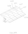
- the transfer guard system includes multiple transfer guard segments or members having upper transfer surfaces for being positioned laterally side-by-side and longitudinally end-to-end along a gap in a belt conveying surface or between two conveying surfaces.
- One advantage of the end-to-end mounting of the transfer guard members is that it allows the user to customize the transfer guard system for use in various different size gaps between conveying surfaces, as well as to accommodate various types and configurations of conveying surfaces. For example, a large range of gap sizes between conveying surfaces may be spanned with only a few differently sized members.
- the transfer guard members may be mounted to an elongated mounting member in a plurality of different locations in the gap, particularly when two differently sized transfer guard members are used to span the gap on either side of the elongate mounting member. This allows for greater flexibility for mounting the transfer guard system in a wide range of conveyor system configurations.
- the elongate mounting member extends laterally across the width of the conveyor system and has the transfer guard members releasably mounted thereto.
- the mounting member is positioned in the gap between conveying surfaces so that the mounting member is generally below the transfer guard members, and specifically the upper surfaces thereof.
- the transfer guard members and lower mounting member have lower detachable connections therebetween. In this manner, the transfer guard members can detach from the mounting member should debris get jammed between one of the transfer guard members and the conveying surface with enough force to dislodge the transfer guard member from the mounting member by releasing the detachable connection therebetween.
- the upper surfaces of the transfer guard members are sized in a longitudinal conveyor or product travel direction to each span a portion of the gap so that when an appropriately sized pair of upstream and downstream transfer guard members are installed a receiving edge of the upstream transfer guard upper surface is closely positioned to the upstream conveying surface and a discharge edge of a downstream transfer guard member is closely positioned to the downstream conveying surface.
- the detachable connections provided between the transfer guard members and lower mounting member are configured to fix the upper surfaces, including the upstream receiving and downstream discharge edges thereof, against longitudinal shifting in the conveyor or product travel direction prior to the detachment of the transfer guard members so that debris does not accumulate in the gap under the transfer guard members during normal conveyor operations.
- Each transfer guard member may include two pairs of spaced-apart legs generally projecting downward from a transfer guard upper bridge portion on which the upper transfer surface is formed.
- the pairs of opposing legs may be laterally offset so that the side surfaces of the transfer guard members are aligned when mounted on a mounting member end-to-end.
- This offset configuration allows the transfer guard members to be mounted on the same mounting member end-to-end with the one of the pairs of legs of one of the end-to-end transfer guard members disposed between the pairs of legs of the other transfer guard member in a configuration resembling the interlocking teeth of a zipper.
- Such an offset configuration allows the spaced-apart legs for each transfer guard member have an identical size and configuration.
- the pairs of opposing legs could be configured such that the side surfaces of the transfer guard members are not aligned when the members are mounted end-to-end. Further, the transfer guard member could alternatively have a single pair of opposing legs.
- the transfer guard members may be formed from a material presenting a surface with good abrasion resistance and a low coefficient of friction such as UHMW polyethylene, or the like.
- the mounting member may be formed of a metal or like material providing high strength and durability.
- transfer guard members are illustrated bridging a gap formed between two adjacent conveyor belt surfaces, they may also be used to bridge a gap between various other types of conveying surfaces, such as, without limitation, between the rollers of two roller conveyor systems that do not use a belt, between one roller conveyor system and another conveyor belt system, between a moving conveying surface and a stationary conveying surface, such as a chute, or in a gap in a conveyor belt, e.g., as a hitch guard.
- the adjacent pulleys shown in the drawings have the same or a similar diameter, the transfer guards may be implemented or be modified to bridge the gap formed between pulleys having different diameters, or to bridge the gap between conveying surfaces that are inclined with respect to one another.
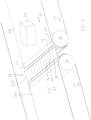
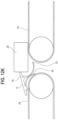
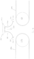
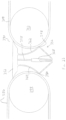
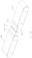
- the transfer guard members 12 each include a body 28 having an upper portion 30 and a pair of lower, resilient legs 40, 42 separated by a gap.
- the body upper portion 30 has a bridge portion 34 with a generally flat upper surface 36 for providing support to objects, such as a box 29 being conveyed between the upstream and downstream belts 18, 20, as well as keeping materials from falling or getting trapped between the belts 18, 20.
- the bridge portion 34 has upstream and downstream outboard portions 35, 37 configured to slidingly engage the conveyor belts 18, 20 and facilitate movement of objects onto and off of the flat upper surface 36.
- the spaced, resilient legs 40, 42 slidingly engaging the conveyor belts 18, 20 and support the body 28 in the gap 22 between the conveyor belts 18, 20.
- the resilient legs 40, 42 below the bridge portion 34 and includes contact portions 44, 46 for slidingly engaging with the adjacent belts 18, 20 to keep the bridge portion 34 in place.
- the term resilient is intended to refer to the ability of a material or component to elastically deform in response to loading during ordinary use of the material or component.
- the spaced, resilient legs 40, 42 are configured to hold the bridge portion 34 in place while allowing for a resilient response to impacts from conveyed objects, debris, or belt splices, as well as non-catastrophic failure modes that are designed not to damage the belts 18, 20 or pulleys 14, 16.
- the transfer guard member 12 has a tendency to lift up or eject upwardly from the gap 22 between the belts 18, 20.
- the transfer guard segment 12 In the case of an object, such as debris, a metal fastener, or the like, the object will cause the transfer guard segment 12 to resiliently shift upwardly temporarily, or in the extreme case, completely eject from the gap 22, allowing the object to fall in the gap 22, rather than get wedged between the edge 50 and the belt 18 and cause damage to the belt 18.
- the resilient anchoring of the bridge portion 30 within the gap 22 limits the likelihood of causing further damage to the splice, as the transfer guard member 12 uses its resiliency to absorb the impact and then settles back into place after the impact.
- the transfer guard member 12 may simply fall downward through the gap between the belts 18, 20, and may easily be replaced with a new transfer guard member 12.
- the transfer guard member 12 may be ejected upwardly from the gap 22 no matter where the transfer guard member 12 is laterally positioned along the gap 22 across the entire width of the belts 18, 20. If sufficient downward force is applied to the transfer guard member 12, such as the edge 50 of the upstream outboard portion 35 getting stuck on a severely damaged belt splice, the transfer guard member 12 may fall downwardly from the gap 22 no matter where the transfer guard member 12 is laterally positioned along the gap 22.
- the transfer guard members 12 allow the items that are intended to be conveyed to pass smoothly over the gap 22, but can dislodge when objects or damaged belt splices strongly impact an edge of the transfer guard member 12 to help avoid belt or splice damage.
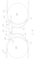
- the transfer guard members 12 have their upper surfaces 36 sized so as to longitudinally span the gap 22 between belts 18, 20 and adjacent pulleys 14, 16.
- the transfer guard members 12 can be positioned so that there are no lateral gaps between adjacent transfer guard members 12, with adjacent sides 24, 26 thereof abutting one another.
- the embodiments herein are described with relation to a gap between two separate conveyor belts, the transfer guard members may also be used in a gap in a single conveyor belt such as between adjacent hitch rollers.
- conveying surfaces may encompass two portions of a single surface, e.g., portions of a conveyor belt surface on opposite sides of a gap formed by a hitch in the conveyor belt.
- the transfer guard system 10 could be implemented or be modified to be used with conveyor systems having rollers or pulleys with different diameters, to span different sized gaps, to span gaps between belts or rollers having different elevations or angular orientations, to span between roller type conveyors without a belt, between a belt or roller conveyor and a chute, or other known conveyor systems, as would be apparent to one of ordinary skill in the art.
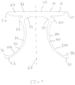
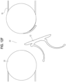
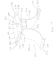
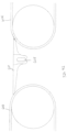
- the transfer guard member 12 has a generally ⁇ -shaped configuration, as shown in FIGS. 2 and 3 .
- the transfer guard member body 28 may be made of a resilient, low friction material such as polymer, for example, ultra-high-molecular-weight (UHMW) polyethylene.
- the body 28 includes the upper bridge portion 34 and the pair of depending legs 40, 42 that can resiliently flex to engage with the adjacent belts 18, 20 as they travel around a lower portion of the adjacent pulleys 14, 16 to releasably anchor the bridge portion 34 in the gap 22.
- the legs 40, 42 may extend beyond the upstream and downstream edges 50, 52 of the bridge portion 10 when the legs 40, 42 are in an unbiased configuration prior to insertion between adjacent pulleys 14, 16.
- the transfer guard bridge portion 34 includes the opposing upstream and downstream outboard portions 35, 37 extending from a central portion 54 of the bridge portion 34.
- the outboard portions 35, 37 extend onto the conveyor belts 18, 20 and are configured to slidingly engage the surfaces of the conveyor belts 18, 20.
- the outboard portion 35 positions the receiving, upstream edge 50 in close proximity to the conveyor belt 18 traveling in direction 60 and returning in direction 62 about the upstream pulley 14 and the discharge, downstream edge 52 of the downstream outboard portion 37 in close proximity to the belt 20 traveling in direction 64 and returning in direction 66 about the downstream pulley 16.
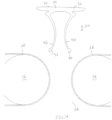
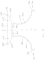
- the transfer guard members 12 are symmetrical about a central, vertical axis 68 as shown in FIG. 3 so as to allow the transfer guard members 12 to be installed with either outboard portion 35, 37 projecting upstream or downstream. This improves the ease of installation of the transfer guard members 12 in the gap 22 and reduces the likelihood of user error in the installation process.
- the conveyor belts 18, 20 may convey items in two opposite directions such that the belt 18 is an upstream belt with the belts 18, 20 operating in a first direction and the belt 20 is the upstream belt with the belts 18, 20 operating in a second, opposite direction.
- the symmetry about the vertical axis 68 permits the transfer guard member 12 to be bi-directional and transfer items across the gap 22 regardless of the direction of the belts 18, 20. Further, an operator does not have to change the orientation of the transfer guard members 12 before changing the direction of the conveyor belts 18, 20 since the transfer guard members 12 are functional in both directions.
- the legs 40, 42 are configured to provide contact portions 44, 46 that are biased against the belts 18, 20 with sufficient force to resist the tendency of the bridge portion 34 to rotate due to forces caused by the adjacent belts 18, 20 moving past the transfer guard member 12 (including a downward frictional force component on the upstream outboard portion 35 from the upstream belt 18 and an upward frictional force component on the downstream outboard portion 37 from the downstream belt 20) and to keep the transfer guard member 12 from being dislodged from the gap 22 between the pulleys 14, 16 during operation of the conveyor belts 18, 20.
- the legs 40, 42 are configured to limit the size of the contact portions 44, 46 and the force with which the contact portions 44, 46 are urged against the belts 18, 20 to minimize wear on the legs 40, 42 and belts 18, 20 and avoid chattering of the legs 40, 42 with the belts 18, 20.
- the transfer guard member body 28 includes one or more transition portions 70, 72 extending from the bridge portion 34 that provide rigidity to the legs 40, 42 and urge the legs 40, 42 against the conveyor belts 18, 20.
- the transfer guard member body 28 includes at least one stop, such as a stop portions 80, 82, for limiting movement of the transfer guard member 12 in the gap 22 during operation of the conveyor belts 18, 20, as discussed in greater detail below.
- the legs 40, 42 extend downwardly from the transition portions 70, 72 and form extended arcuate portions 84, 86 that initially curve inwardly toward each other and then extend downward and away from each other.
- Each leg 40, 42 includes a distal end portion 90, 92 with contact surfaces 94, 96 for contacting the adjacent belt 18, 20 during normal operation.
- the distal end portions 90, 92 have rounded protrusions with the contact surfaces 94, 96 thereon.
- the arcuate portions 84, 86 may be sized and configured such that outer facing surfaces 100, 102 of the arcuate portions 84, 86 do not engage with belts 18, 20 during normal operation, but upon impact of an object with the bridge portion 34, the outer facing surfaces 100, 102 may be urged into engagement with the belts 18, 20 and provide anchoring support to the bridge portion 34 to help absorb the impact and prevent ejection of the transfer guard member 12 from the gap 22.
- the transition portions 70, 72 connect the legs 40, 42 to the bridge portion 34, the legs 40, 42 may be directly connected to the bridge portion 34 in other forms. Further, the shape, size, and orientation of the transition portions 70, 72 and legs 40, 42 may be selected to provide a desired amount of sliding engagement with the conveying surfaces in a particular application.
- the legs 40, 42 have an unbiased, expanded configuration with the legs 40, 42 splayed apart as shown in FIG. 3 .
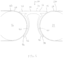
- the legs 40, 42 are urged together to a deflected, insertion configuration as shown in FIG. 4 .
- the distal end portions 90, 92 are biased inwardly toward one another to provide clearance for the distal end portions 90, 92 to fit into the gap 22 between the conveyor belts 18, 20.
- the legs 40, 42 are spaced apart in the deflected, insertion configuration and do not overlap laterally across the transfer guard member 12.
- the distal end portions 90, 92 advanced below centerlines of the pulleys 14, 16 the legs 40, 42 shift apart toward an expanded, installation configuration and resiliently bias the contact surfaces 94, 96 against the conveyor belts 18, 20.
- the bridge portion 31 may contact the belts 18, 20 below the upper surfaces 120, 122 of the belts 18, 20 to provide for smooth transfer of objects from the belt 18 to the upper transfer surface 36 and subsequently to the downstream belt 20.
- the contact surfaces 94, 96 may engage the adjacent belts 18, 20 below the centerlines of the pulleys 14, 16, and may engage the adjacent belts 18, 20 closer to the lower extent of the pulleys 14, 16 so that the legs 40, 42 must be flexed significantly in order to expel the transfer guard member 12 from the gap 22.
- the transfer guard member 12 may have only a single downstream leg 42 to engage the conveyor belt 20.
- the single downstream leg 42 would provide sufficient engagement with conveyor belt 20 to resist the upwardly directed forces on the downstream outboard portion 37 from the conveyor belt 20 and the downwardly directed forces on the upstream outboard portion 35.
- the transfer guard member 12 may have three, four, or another number of members or devices for engaging one or both of the conveying surfaces.
- the transfer guard member 12 may be integrally formed from a single piece of material, such as UHMW polyethylene.
- the term integral is intended to refer to a single, one-piece construction.
- the transfer guard member 12 is formed by extruding UNMW polyethylene through a die having the desired cross sectional shape of the transfer guard member 12.
- the transfer guard member 12 could alternatively be formed by casting, injection moulding, machining, or three dimensional printing, for example.
- the transfer guard member 12 could be formed from a plurality of components connected together.
- the transfer guard member 12 could have a two-part construction including the bridge portion 34 formed of a first material and the legs 40, 42 formed of a second material that is secured to the bridge portion 34 using welding or fasteners, for example.
- a user may cut the lateral extension 136 of the transfer guard member 12A along an axis 138 to obtain a desired width 140 of the transfer guard 12A. Because the lateral extension 136 is positioned laterally from legs 142 of the transfer guard member 12A, a user does not need to cut through the legs 142 in order to obtain a desired width 140 of the transfer guard 12A, which makes customization easier.
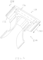
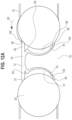
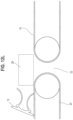
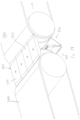
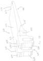
- FIGS. 7 and 7A another transfer guard member 150 is provided that is similar in many respects to the transfer guard member 12.
- the transfer guard member 150 is shown installed in a gap 152 between two moving conveyor belts 154, 156.
- the transfer guard member 150 has a bridge portion 157 with upstream and downstream outboard portions 158, 160 slidingly engaged with the conveyor belts 154, 156 in an upper, enlarged area 162 of the gap 152.
- the conveyor belts 154, 156 have a narrowed area 164 that defines a minimum distance 166 between the conveyor belts 154, 156 and a lower, enlarged area 170 below the narrowed area 164.
- the transfer guard member 150 has lower, resilient legs 174, 176 with distal end portions 178, 180 slidingly engaged with the belts 154, 156 in the lower, enlarged area 170 of the gap 152. Intermediate the outboard portions 158, 160 and the legs 174, 176, the transfer guard member 150 has stop portions 182, 184 spaced from the conveyor belts 154, 156 as shown in FIG. 6 . During normal operation, the outboard portions 158, 160 rest on the moving conveyor belts 154, 156 in the upper area 162 of the gap 152 and the legs 174, 176 bias the distal end portions 178, 180 against the moving conveyor belts 154, 156 in the lower area 170 of the gap 152 which holds the transfer guard member 150 within the gap 152.
- the transfer guard member 150 has freedom to shift within the gap 152 and navigate significantly damaged conveying surfaces without causing further damage to the conveying surfaces.
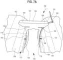
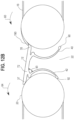
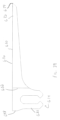
- the conveyor belt 154 is shown having been cut and a large flap 190 is upstanding from the conveyor belt 154.
- the conveyor belt 154 moves in direction 192 and advances the flap 190 into contact with an upstream edge 191 of the upstream outboard portion 158.
- the flap 190 moving in direction 192 engages the upstream edge 191 of the transfer guard member 150 and shifts the bridge portion 157 in direction 194. This presses a downstream edge 196 of the outboard portion 160 against the conveyor belt 156.
- the flap 190 continues to move in direction 192 around the pulley associated with the conveyor belt 154 and shifts the bridge portion 157 farther in direction 194 which engages a lower surface 200 of the outboard portion 160 with the conveyor belt 156. Further, the shifting of the bridge portion 157 in direction 194 engages the stop portion 184 with the conveyor belt 156.
- the transfer guard member 150 is engaged with the conveyor belt 156 at three areas-the outboard portion edge 196 and lower surface 200, the stop portion 184, and the leg distal end portion 180. These three engagement areas temporarily couple the transfer guard member 150 to the conveyor belt 156.
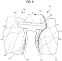
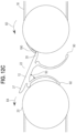
- the conveyor belt 156 continues to rotate in direction 193 about its associated pulley.
- the transfer guard member 150 is temporarily coupled to the conveyor belt 156, the rotation of the conveyor belt 156 in direction 193 causes the bridge portion 157 to tilt and raise the upstream edge 191 upward in direction 202, over the flap 190 of the conveyor belt 154.
- the upstream leg 174 is resiliently tensioned in response to the flap 190 urging the bridge portion 157 downstream in direction 194 and moved an arcuate outer surface 204 of the upstream leg 174 away from the conveyor belt 154, as shown in FIG. 10 .
- the leg 174 springs back and draws the bridge portion 157 upstream in direction 206.
- the sliding engagement of the leg distal end portion 178 and the conveyor belt 154 traveling in direction 192 causes the leg 174 to pull downward on the outboard portion 158 and direct the upstream edge 191 downward behind the flap 190.
- the movement of the bridge portion 157 in direction 206 disengages the stop portion 184 from the conveyor belt 156 and permits the stop portion 184 to move in direction 206 away from the conveyor belt 156.
- the transfer guard member 157 is now engaged with the conveyor belt 156 at only two areas-the downstream outboard portion edge 196 and lower surface 200 and the leg distal end portion 180.
- the fewer points of contact between the transfer guard member 150 and the conveyor belt 154 effectively de-couples the transfer guard member 150 from the conveyor belt 154 moving in direction 193 such that the outboard portion 160 and distal end portion 180 return to normal, sliding engagement with the conveyor belt 156.
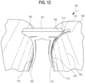
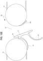
- the upstream edge 191 of the transfer guard member 150 has successfully navigated up and over the flap 190.
- the flap 190 has started to travel along a lower surface 210 of the upstream outboard portion 158 and toward the leg 174.
- the flap 190 may travel along the outer arcuate surface 204 of the leg 174, the distal end portion 178, and away from the transfer guard member 150 in direction 192.
- the transfer guard member 150 may navigate upward over large irregularities in a conveyor belt 154 without further damaging the conveyor belt 154.
- the irregularity will pull the upstream outboard portion 158 in direction 192 with the irregularity.
- the bridge portion 157 would fold toward the downstream leg 180 in order to permit the upstream outboard portion 158 to move in direction 192 with the irregularity.
- the irregularity would continue to pull the transfer guard member 150 with it in direction 192 until the transfer guard member 150 falls downwardly out of the gap 152.
- the transfer guard member 150 slidingly engages the conveyor belts 154, 156 and holds itself in the gap 152, the transfer guard member 150 can fall downwardly out of the gap 152 without interference from any rigid mounting structures. This further reduces the likelihood that the transfer guard member 150 could become lodged against the conveyor belt 154 and damage the conveyor belt 154 due to the irregularity. It will be appreciated that the transfer guard member 12 may operate in a manner similar to the foregoing description of the transfer guard member 150.
- the transfer guard member 12 may be ejected upwardly or downwardly from the gap 22 in response to a substantial force being applied to the bridge portion 34. By ejecting from the gap 22, the transfer guard member 12 avoids damaging the conveyor belts 18, 20 by not becoming lodged or wedged against the conveyor belts 18, 20.
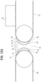
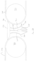
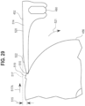
- the transfer guard member 12 is shown in its normal operating configuration with upper body portion 34 in an operating orientation for conveying goods across the gap 22 and the upstream and downstream outboard portions 35, 37 and the leg distal end portions 90, 92 are slidingly engaged with the conveyor belts 18, 20.
- the stop portions 80, 82 and outer, arcuate surfaces 100, 102 of the legs 40, 42 are spaced from the conveyor belts 18, 20 by air gaps 89, 91.
- the conveyor belt 18 travels in direction 60 and has a flap 190A traveling into contact against the upstream edge 50.
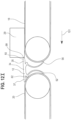
- the flap 190A engages the upstream outboard portion 34 and lifts and tilts the bridge portion 34 within the gap 22.
- the engagement of the flap 190A against the upstream outboard portion 35 shifts the bridge portion 34 downstream and engages the stop portion 82 against the conveyor belt 20.
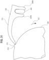
- the flap 190A is distinguishable from the flap 190 discussed above with respect to FIGS.
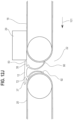
- the flap 190A of the conveyor belt 18 has lifted the bridge portion 34 to an inclined, failure orientation wherein the bridge portion may fall through the gap 22. This movement of the bridge portion 34 further bends the leg 42 relative to the transition portion 72.
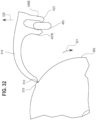
- the flap portion 190A continues traveling in direction 160 away from the bridge portion 34 while the transfer guard member 12 falls downward from the gap 22. As shown in FIGS. 12A-12F , the transfer guard member 12 may eject downwardly from the gap rather than becoming wedged on the flap 190A and further damaging the conveyor belt 18.
- the box 29 travels along the conveyor belt 18 in a conveying direction 101 and, due to the engagement of the corner 99 with the edge 50, shifts the bridge portion 34 downstream and engages the stop portion 82 against the conveyor belt 20.
- the continued movement of the box 29 in direction 101 applies sufficient force to cam a curved lower surface of the outboard portion 37 up and out of engagement with the conveyor belt 20.
- the heavy box 29 does not deflect in response to contact or engagement with the upstream outboard portion 35 and applies sufficiently high force against the bridge portion 34 to dislodge the bridge portion 34 from the gap 22.
- the movement of the box 29 in downstream direction 101 shifts the bridge portion 34 downstream which bends the leg 92 relative to the transition portion 72 by a greater and greater amount as the bridge portion 34 is removed from the gap 22.
- the transfer guard member 12 has been fully ejected from the gap 22 by the block 29.
- the laterally adjacent transfer guard members 12 of the transfer guard system 10 may support the box 29 as it travels across the gap 22. Further, the transfer guard member 12 is able to eject upwardly from the gap 22 without becoming wedged against the conveyor belt 12 and damaging the conveyor belt 20.
- the transfer guard member may eject upwardly or downwardly from the gap 22 to accommodate out-of-the ordinary forces being applied to the transfer guard member 12 without causing damage to the conveyor belts 18, 20. It will be appreciated at the loading required to dislodge the transfer guard member 12 may be rarely, if ever, encountered by a transfer guard system 10 in normal use. But, when it does occur, the transfer guard system 10 provides improved ability to handle the loading without damaging the conveyor belts 18, 20.
- FIGS. 13-18 another transfer guard system 250 is provided that is similar in many respects to the transfer guard system 10, the transfer guard system 250 is configured for bridging a gap 252 between conveying surfaces such as conveyor belts 254, 256.
- the transfer guard system 250 includes a plurality of transfer guard members 260 that are similar to the transfer guard members 12 such that differences between the transfer guard members 12, 260 will be highlighted.
- the transfer guard member 260 has a body 262 with an upper bridge portion 264, as shown in FIG. 14 .
- the bridge portion 264 has a substantially flat upper surface 265 and upstream and downstream outboard portions 270, 272 with different configurations than the upstream and downstream outboard portions 35, 37 of the transfer guard member 12.
- the upstream outboard portion 270 has a lower inclined surface 274 that tapers downstream away and down from an upstream edge 276.
- the lower inclined surface 274 has a smaller radius of curvature than an upstream pulley 280 so as to minimize the contact surface between the bridge portion 264 and the belt 254 to reduce the amount of friction therebetween and to avoid chattering, i.e.
- a similar lower inclined surface 275 is provided on the downstream outboard portion 272.
- the outboard portions 270, 272 also include upper inclined surface portions 284, 286 to facilitate a smooth transfer of conveyed objects from the belt 254 to the upper surface 265 of the bridge portion 264 and likewise from the upper surface 264 to the downstream belt 256.
- the upper and lower surfaces 284, 286 and 274, 275 could have other constructions, such as an arcuate configuration that matches the contour of the adjacent pulley or other conveying surface, or a non-arcuate or flat configuration so as to give the outboard portions 270, 272 a wedge-shaped configuration.
- the lower inclined surfaces 274, 275 can act as abutment surfaces against the adjacent belts 254, 256 when the bridge portion 264 experiences an impact from a belt splice or an object traveling on the conveyor surface.
- the body 260 has a pair of resilient legs 290, 292 that are connected to and extend initially downwardly from a central portion of an underside 296 of the bridge portion 264.
- Each leg 290, 292 then includes a longitudinally extending portion 298, 300 that is offset from the underside 296 of bridge portion 264 and extends towards the outboard portions 270, 272.
- These portions 298, 300 are generally parallel to the upper surface 265.
- the legs 290, 292 are connected to the bridge portion 264 near the center, they could be connected at other portions of underside 296 of the bridge portion 264. Further, the longitudinally extending portions 298, 300 could be omitted such that extended arcuate portions 302, 304 of the legs 290, 292 could be directly connected to the bridge portion 264, similarly to the embodiment shown in FIGS. 19-23 . However, the configuration shown provides additional flexibility to the legs 290, 292 that may be desirable for many applications.
- the legs 362, 364 are interconnected at their ends with an actuator engagement portion 368.
- the resilient legs 362, 364 include arcuate portions 370, 372 that extend generally downward and away from each other. The legs 362, 364 then turn back inwards toward one another along inwardly extending portions 374, 376.
- the intersection between the arcuate portions 370, 372 and inwardly extending portions 374, 376 form protruding abutment portions 378, 380 that are configured to engage with the adjacent belts 382, 384 at contact surfaces 386, 388 during normal operation.
- the arcuate portions 370, 372 may be sized and configured such that the outer facing surfaces 370A, 372A do not engage with belts 382, 384 during normal operation, but upon impact of an object with the bridge portion 354, the outer facing surfaces 370A, 372A may be urged into engagement with the adjacent belt 382, 384 and provide support to the bridge portion 354 to help absorb the impact and prevent expulsion of the transfer guard member 352.
- the legs 362, 364 are configured to provide the small contact surfaces 386, 388 that are biased against adjacent belts 382, 384 with sufficient force to resist the tendency of the bridge portion 354 to rotate due to engagement with the forces exerted by the adjacent belts 382, 384 and to keep the transfer guard member 352 from unnecessarily being dislodged from a gap 390 between pulleys 392, 394.
- the contact surfaces 386, 388 of the legs 362, 364 are too large or are biased against the adjacent belts 382, 384 with too much force, the friction generated can cause premature wear on the legs 362, 364 and the belts 382, 384, and may also cause undesirable chattering.
- the actuator engagement portion 368 includes a vertically oriented throughbore 400 (shown in FIG. 21 ) into which the threaded fastener 358 extends.
- the throughbore 400 may be sized to receive a nut for threadingly engaging with the threaded fastener 358, or the throughbore 400 itself may be threaded.
- the threaded fastener 358 includes a head portion 402 with a flat top that is rotatably disposed in the opening 360 that extends through the bridge portion 354 and is coaxial with throughbore 400.
- the fastener head portion 402 lies flush with or recessed below an upper surface 404 of the bridge portion 354 so as to not interfere with objects being conveyed across the bridge surface 404.
- FIGS. 22 and 23 demonstrate the legs 362, 364 in a first unexpanded orientation ( FIG. 22 ) and an expanded orientation ( FIG. 23 ), wherein the protruding abutment portions 378, 380 have been expanded until they are in engagement with the adjacent belts 384, 386.
- the user may choose the amount biasing force applied by the protruding abutment portions 378, 380 on the belts 384, 386.
- This adjustability is advantageous for fine tuning the transfer guard 352 to its environment. For example, if more stability is required, the user may expand the legs 362, 364 to exert more force on the adjacent belts 384, 386. If stability is less of a concern, the user may adjust the legs 362, 364 to exert a relatively small amount of pressure on the adjacent belts to reduce wear on the abutment portions 378, 380.
- the transfer guard member 352 may be configured to interact with a position sensor to provide a signal when one or more of the members 352 are out of position.
- a throughbore may be provided through the body of the bridge portion 354 similar to the one shown in FIG. 14 for interacting with a sensor.
- the throughbore may be positioned off-center to accommodate the fastener 358.
- sensors such as contactors, wires, photoelectric eyes, etc., may be used for this purpose.
- the transfer guard members 12, 150, 260, and 352 advantageously are modular and therefore may be used in combination to span the gap along the entire lateral width of a conveyor system or adjacent conveyor systems. In addition, if one of the plurality of the transfer guard members becomes damaged or worn, it may be replaced without needing to replace or disturb the other transfer guard members. In another form, a transfer guard system utilizing the transfer guard members 12, 150, 260, 352 may have a single, elongated transfer guard member 12, 150, 260, 352 bridging the gap between the conveying surfaces rather than a plurality of transfer guard memebrs.
- the floating transfer guard members 12, 150, 260, 352 are self-supporting, and need no additional structural supports to be bought or fabricated for their installment. Further, no tools (other than a driver for the embodiment shown in FIGS. 19-23 ) are needed for installation. In addition, if the adjacent pulleys are crowned, no modification of the transfer guard members may be required, as the transfer guard members simply will follow the curvature of the pulleys. This eliminates the need for a curved support bar or a custom-made curved bridge portion.
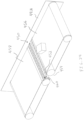
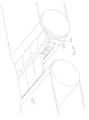
- FIGS. 24-36 Another transfer guard system 450 in accordance with the present invention is disclosed in FIGS. 24-36 .
- the transfer guard system 450 includes several transfer guard members 452 ( FIGS. 25-28 ) that extend across a laterally extending gap 454 between conveying surfaces, such as adjacent belts 456, 458.
- the transfer guard members 452 have attachment members 459 for forming detachable connections 462 with an elongate mounting member, such as a mounting bar 460, which is disposed in the gap 454.
- the detachable connections 462 and mounting bar 460 are similar to those described in U.S. Patent No. 8,365,899 , which is hereby incorporated by reference in its entirety.
- the transfer guard member 452 can detach from the mounting bar 460 via the detachable connection 462 therebetween immediately below an upper, transfer surface 464 of the transfer guard member 102.
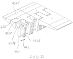
- transfer guard members 441 are provided including upstream and downstream transfer guard members 441A, 441B that have less than the entire upstream transfer guard member 441A longitudinally aligned with the downstream transfer guard member 441B.
- Each transfer guard member 441 has an attachment member 443 with a single bridge portion 445 and a pair of recesses 445, 447. When the transfer guard members 441 are mounted to a mounting bar, the bridge portion 445 of each transfer guard member 441 is positioned in the the recesses 445, 447 of two adjacent transfer guard members 441. As shown in FIGS.
- the sizes described are merely examples, and other size members could be used to span different size gaps.
- the transfer guard members 452 are configured to be easily modified to span gaps that fall in between the sizes of the transfer guard members, i.e. a 7.5-inch gap could be spanned by a five-inch member and a three-inch member by shortening the length of one or both of the members as necessary.
- a 7.5-inch gap could be spanned by a five-inch member and a three-inch member by shortening the length of one or both of the members as necessary.
- such modification may not be necessary in many cases, as the gap sizes between conveyor surfaces may vary at different elevations between the conveyor surfaces. For example, as shown in FIG.
- the space between the pulleys 476, 478 varies due to their arcuate profile, i.e., the gap is larger near the tops of the pulleys 476, 478 than it is at the middle between their centers. Accordingly, if the transfer guard members 452, are slightly too short, they may be mounted slightly lower in the gap 454 where the pulleys 476, 478 are closer together, and vice versa.
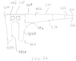
- the pairs of legs 484, 486 includes outer legs 485A, 485B and inner legs 487A, 487B.
- the pairs of legs 484, 486 are spaced apart by the lateral width of one of the pairs of legs 484, 486, and the pair of legs 484 is offset from one side 472 of the transfer guard member 452 such that the pairs of legs 484, 486 of a second (i.e. downstream) transfer guard member 452B can be interdigitated in a zipper-like fashion with the legs pairs 484, 486 of the first (i.e. upstream) transfer guard member 452A, as shown in FIGS. 24 and 27 .
- the interdigitated leg 484, 486 pairs of the end-to-end transfer guard members 452A, 452B provide a discontinuous transverse gap or seam 490 between the members 452A, 452B that is less likely to interfere with conveyed product than a continuous transverse seam between each pair of end-to-end transfer guard member 452.
- any laterally-oriented gaps that might form between outer facing surfaces 492, 494 of the leg pairs 484, 486 of one of the end-to-end transfer guard members 452 and corresponding flat surface portions 496, 498 adjacent the leg pairs 484, 486 of the other of the end-to-end transfer guard member 452 would be longitudinally spaced apart from one another so as to not result in a single gap that spans across the lateral width of the transfer guard system 450 that might snag small products or collect debris.
- the two transfer guard members 452A, 452B may be mounted to the bar 460 end-to-end such that the lateral sides 472 are aligned.
- Other configurations of legs 484, 486 may be used, including using a single pair legs offset on one side of the transfer guard member 452, or spaced apart leg pairs located at both sides 472 such that the mating transfer guard members 452 would have a centrally located pair of legs to be located between the spaced-apart legs of the other transfer guard member 452.
- the transfer guard member 102 could have more than two pairs of spaced-apart legs 484, 486.
- Each leg pair 484, 486 includes a protrusion 500, 502 on the outer facing surface 492, 494 of the outer legs 485A, 485B as shown in FIG. 25 .
- the protrusions 500, 502 engage with corresponding flat surface portions 496, 498 adjacent the pairs of legs 484, 486 of the opposite transfer guard member 452 with an interference fit.
- the interference fit creates a clash between the transfer guard members 452A, 452B that keeps gaps from forming between the outer facing surfaces 492, 494 of the outer legs 485A, 485B and the flat surface portions 496, 498.
- the upstream transfer guard member 452A has an upstream outboard portion 514A extending outward from the bridge portion 482A thereof and the downstream transfer guard member 452B has a downstream outboard portion 514B extending outward from the bridge portion 482B thereof.
- the transfer surfaces of each of the transfer guard members 452A, 452B include a flat surface portion 518 of the bridge portion 482, a substantially flat surface portion 520 of the outboard portion 514, and a downwardly inclined tapered surface portion 522 of the outboard portion 514 tapering toward the outer edge 510.
- the outboard portions 514A, 514B extend into close proximity with the adjacent belts 456, 458 so the edge 510A of the transfer guard member 452A is an upstream receiving edge closely adjacent the moving belt 456 and the edge 510B is a downstream discharge edge closely adjacent the moving belt 458, as shown in FIG. 24A .
- the outboard portions 514 of the transfer guard members 452A, 452B have a lower inclined surface 526 that tapers downstream away and down from the thin upstream edge 510 so as to generally follow the belt 456, 458 as it travels down about the corresponding pulley 476, 478. Debris that gets stuck may get caught between the belt 456, 458 extending about the pulley 476, 478 and the lower inclined surface 526.
- the lower inclined surface 526 could have other constructions, such as an arcuate configuration so as to even more closely follow the path of the belts 456, 458 about the pulleys 476, 478. So configured, the outboard portions 514 have a generally wedge-shaped configuration. Naturally, other configurations of the outboard portions are possible, and may be adapted for spanning gaps between various different types and orientations of adjacent conveying surfaces.
- the transfer guard system 450 includes a pair of mounts 550 each having a front plate 566, which are discussed in greater detail below, for installing the mounting bar 460 in the gap 454 and the transfer guard members 452 includes an end transfer guard member 452C that receives the mount 550 and maintains the mount 550 within the profile of the transfer guard members 452.
- the end transfer guard member 452C has a narrowed bridge portion 482C with correspondingly narrowed legs 485B, 487B. The narrowed bridge portion 482C and legs 485B, 487B provide a third recess 498C of the end transfer guard member 452C.
- the third recess 498C provides a lateral space 491 along the mounting bar 460 for the mount 550 which permits the mounts 550 of the transfer guard system 450 to generally be laterally positioned inward from the outer lateral sides 472 of the outermost transfer guard members 452C, 452D. Because the mounts 550 are positioned laterally inward from the outer lateral sides 472 of the outermost transfer guard members 452C, 452D, the outer lateral sides 472 of the outermost transfer guard members 452C, 452D can be butted up against or adjacent to skirts 491A (see FIG. 24 ) or other structures on opposite sides of the conveyor belts 456, 458 to minimize the longitudinal gaps between the outer lateral sides of the conveyor belts 456, 458 and the skirts 491A which could catch debris or conveyed goods.
- each mount 550 has fasteners, such as bolts 575, for releasably securing the front plate 566 to a rear plate 556 of the mount 550.
- the recess 482C of the end transfer guard member 452C permits the bolts 575 to be readily accessed by a user to release the front plates 566 from the rear plates 556 and remove the mounting bar 460, transfer guard members 452, and front plates 466 from the gap 455 such as for replacing one of the transfer guard members 452.
- the outboard portions 514 of the transfer guard members 452 are configured to encourage deflection of outboard portion 514 and avoid straight-on loading that could result in very little deflection of the outboard portion 514 and cause the edge 510 to damage the conveyor belt 456.
- the tapered surface portion 522 extends downwardly from the flat surface portion 520 and vertically offsets the edge 510 a distance 515 from an axis 517 extending along the flat surface portion 520. By vertically offsetting the edge 510 below the axis 517, the outboard portion 514 is more likely to bend downwardly in response to loading in direction 517A at the edge 510.
- the damaged splice 519 continues to move in direction 521 and pull the edge 510 downwardly, further bending the outboard portion 514 until a distal end 523 of the leg 485B disengages from the mounting bar 460.
- the released transfer guard member 452 may eject upward generally in direction 525 from the gap 454 or may fall downward through the gap 454 clear of the conveyor belt 456 rather than the edge 510 becoming wedged against the conveyor belt 456.
- the transfer guard member 452 is made of a material that is sufficiently strong to resist loading from conveying surfaces and conveyed goods during normal operation.
- the transfer guard members 452 are also sufficiently resilient to permit the legs 484, 486 to deflect apart to snap onto the mounting bar 460 and snap off of the mounting bar 460 if a sufficiently high force is applied at the edge 510 without damaging the conveyor belt 456.
- the transfer guard member 452 may be made of, for example, a polymer such as UHMW polyethylene or high-density polyethylene.
- the mounting bar 460 may be made of a material sufficiently rigid to withstand loading during conveyor operations, such as polymer or a metal, such a steel, fiberglass, and carbon fiber.
- the transfer guard member 452 may be integrally formed from a single material, or may be formed from separate components.
- the attachment and outboard portions 459, 514 of the transfer guard member 452 may be made of separate materials and connected together using welding or fasteners.
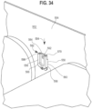
- the transfer guard system 450 includes one or more mounts 550 as mentioned above that permit easier installation of the mounting bar 460 in constrained environments, such as when the conveyor belts 456, 458 have skirts 552 with guide surfaces 554 thereof extending longitudinally along opposite lateral sides of the conveyor belts 456, 458 to direct conveyed objects.
- constrained environments may be further limited by welds or structural members on outer surfaces of the skirts 552 that inhibit drilling through the skirts 552 to install the mounting bar 460.
- the conveyor belts 456, 458 may have conveyor structure positioned below the gap that prevent access to the bottom of the gap 454.
- the mount 550 may be used to easily and quickly install the mounting bar 460 in the gap 454 despite these environment constraints.
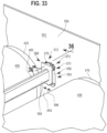
- the mount 550 includes a base portion, such as the rear plate 556, which can be fixed to the surface 554 such as by applying welds 558 at upstream and downstream sides 560 of the rear plate 556 and/or driving one or more fasteners 562 through one or more holes 564 in the rear plate 556 and into the skirt 552, as shown in FIGS. 34 and 36 .
- the mount 550 also includes an end support portion, such as the front plate 566, for being connected to an end portion 568 of the mounting bar 460.
- the mount 550 has a height adjustment mechanism 570 for adjusting the vertical position of the mounting bar 460 in the gap 454 and a longitudinal adjustment mechanism 572 to adjust the longitudinal position of the mounting bar 460 in the gap 454.
- the mount 550 also has a lock device 573 for securing the front plate 566 and mounting bar 460 supported therein to the rear plate 556 once the mounting bar 460 has been positioned in the desired location in the gap 454.
- the lock device 573 includes fasteners such as the bolts 575 that extend through elongated openings 577 of the front plate 566 and engage threaded bores 579 of the rear plate 556.
- the front plate 566 has an opening 574 sized to receive the end portion 568 of the mounting bar 460, such as after a user has cut the mounting bar 460 to a desired length.
- the front plate 566 has a collar portion 576 extending about the opening 574 that contacts the outer surfaces of the mounting bar 460 and resists loading from the mounting bar 460 during operation of the conveyor belts 456, 458.
- the front plate 556 has a lip portion 580 configured to extend laterally over a seat 582 of the rear plate 556, as shown in FIGS. 34 and 36 .
- the lip portion 580 and seat 582 include flat surfaces 584, 586 that face each other with the front plate 566 positioned on or adjacent to the rear plate 556.
- the rear plate 556 has a recess 588 extending downwardly from the seat surface 586 that provides clearance for the mounting bar end portion 568 to be received therein.
- the height adjustment mechanism 572 may include a plurality of height adjustment members, such as shims 590.
- a user may select one or more shims 590 as desired to set the distance between the front plate lip portion 580 and the rear plate seat 582 once the plates 556, 566 have been connected together.
- one of the bolts 575 is advanced into a center through opening 592 of the front plate 566 and threaded into apertures 593 of the shims 590 aligned with the opening 592.
- the user may then advance the mounting bar 460, and front plate 566 and shims 590 connected thereto, generally in direction 594 (see FIG. 34 ) to position the mounting bar end portion 568 in the recess 588 of the rear plate 556 and seat the lowermost shim 590 against the seat surface 586 of the rear plate 556 (see FIG. 36 ).
- the user threads the second bolt 575 through one of the elongated openings 577 of the front plate 566, through corresponding elongated openings in the shims 590, and into the corresponding threaded bore 579 of the rear plate 556.
- the user removes the first bolt 575 from the center opening 592 of the front plate 566 and apertures 593 of the shims 590, then threads the first bolt 575 through the other of the elongated openings 577 of the front plate 566, through corresponding elongated openings in the shims 590, and into the corresponding threaded bore 579 of the rear plate 566.
- the longitudinal position adjustment mechanism 572 includes the elongated openings 577 in the front plate 566 and corresponding elongated holes in the shims 590 which permit the front plate 566 to be shifted in directions 596 after the mounting bar 460 has been lowered into the gap 454.
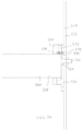
- the transfer guard system 581 includes a plurality of transfer guard members 583 (only one is shown for clarity) connected to a mounting bar 585.
- the transfer guard system 581 has a pair of mounts 587 for securing the mounting bar 585 to a pair of skirts adjacent conveyor belts, for example.
- the mount 587 includes an angle bar 587A having a base portion, e.g. section 587B, for being fixed to one of the skirts and a support portion, e.g., section 587C, for supporting the mounting bar 585.
- the mounting bar 585 has an end portion 585A with a slot 585B sized to receive the section 587C of the angle bar 587A.
- the slot 585B and angle bar section 587C cooperate to permit the mounting bar 585 to be lowered into a gap where the angle bar 587A is mounted and slid onto the angle bar 587A.
- the mounting bar end portion 585A has a hole 585C that aligns with an opening of the angle bar section 587C and permits a fastener to extend through the hole 585C and opening of the angle bar section 587C to fix the mounting bar 585 to the angle bar 587A, such as with a nut threaded onto an end of the fastener.
- the opening of the angle bar section 587C may be vertically elongated to permit vertical adjustment of the mounting bar 585.
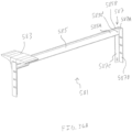
- another transfer guard system 600 is provided for bridging a gap between conveying surfaces, such as a gap 602 between conveyors 604, 606.
- the transfer guard system 600 is similar in many respects to the transfer guard system 450 discussed above such that differences between the two will be highlighted.
- the transfer guard system 600 includes a mounting bar 608 extending laterally across the gap 602 and a pairs of longitudinally aligned transfer guard members 610 releasably fixed to the mounting bar 608.
- the transfer guard members 610 each have a body 612 with an attachment member 614 and an outboard portion 616.
- the attachment member 614 includes bridge portions 618, 620 and pairs of resilient legs 622, 624 depending from the bridge portions 618, 620 for resiliently engaging the mounting bar 608.
- the transfer guard member 610 has a substantially flat upper surface 630 including an outer surface portion 632 of the outboard portion 616, as shown in FIGS. 38 and 39 .
- the outer surface portion 632 extends straight out to an outer edge 634, rather than having an inclined surface like the tapered surface portion 522 of the transfer guard member 452.
- the transfer guard system 600 may have differently sized transfer guard members 610 detachably fixed to the mounting bar 608.
- the transfer guard members may include a two-inch transfer guard member 610A, a three-inch transfer guard member 610B, a five-inch transfer guard member 610C, and a pair of six-inch transfer guard members 610D on an upstream side of the mounting bar 608 and three-inch transfer guard members 610B on a downstream side of the mounting bar 608.
- the transfer guard members 610 may be connected to the mounting bar 608 in a number of different approaches.
- the transfer guard members 610 may be positioned above the mounting bar 608 to align openings 640 of the pairs of legs 622, 624 with the mounting bar 608.
- the transfer guard member 610 is then advanced in direction 642 onto the mounting bar 608.
- the legs 622, 624 have distal end portions with cam surfaces 644 that engage the mounting bar 608 and cause the legs 622, 624 to flex outwardly as the transfer guard member 610 is advanced in direction 642, such as by hammering the transfer guard member 610 onto the mounting bar 608.
- the distal ends of the legs 622, 624 resiliently engage a lower portion of the mounting bar 608 and fix the transfer guard member 610 onto the mounting bar 608.
- the body 612 of transfer guard member 610 includes protrusions 648, 650 that engage flat surface portions 652, 654 of the adjacent transfer guard member 610 to create interference in a manner similar to the protrusions 500, 502 discussed above with respect to transfer guard member 452.
- a transfer guard member e.g., transfer guard member 610B (see FIG.
- the protrusions 500, 502 may operate in a similar manner to take up play of the transfer guard members 452 in the event that one or more of the legs 485A, 485B, 487A, 487B are damaged during installation.
- the transfer guard members 610 may be paired up and positioned so that the pairs of legs 622, 624 of transfer guard members 610 are interdigitated and the openings 640 formed by the legs 622, 624 of the guard members 610 are aligned.
- the mounting bar 608 is then fit into the openings 640 and the pair of transfer guard members 610 are slid along the mounting bar 608 into a desired location therealong.
Landscapes
- Engineering & Computer Science (AREA)
- Mechanical Engineering (AREA)
- Structure Of Belt Conveyors (AREA)
- Chain Conveyers (AREA)
- Rollers For Roller Conveyors For Transfer (AREA)
Applications Claiming Priority (3)
| Application Number | Priority Date | Filing Date | Title |
|---|---|---|---|
| US201461977866P | 2014-04-10 | 2014-04-10 | |
| EP15776877.1A EP3129308B1 (de) | 2014-04-10 | 2015-04-10 | Transferschutz für förderband |
| PCT/US2015/025484 WO2015157740A1 (en) | 2014-04-10 | 2015-04-10 | Conveyor transfer guards |
Related Parent Applications (1)
| Application Number | Title | Priority Date | Filing Date |
|---|---|---|---|
| EP15776877.1A Division EP3129308B1 (de) | 2014-04-10 | 2015-04-10 | Transferschutz für förderband |
Publications (2)
| Publication Number | Publication Date |
|---|---|
| EP4480866A2 true EP4480866A2 (de) | 2024-12-25 |
| EP4480866A3 EP4480866A3 (de) | 2025-03-12 |
Family
ID=54264489
Family Applications (4)
| Application Number | Title | Priority Date | Filing Date |
|---|---|---|---|
| EP15776877.1A Active EP3129308B1 (de) | 2014-04-10 | 2015-04-10 | Transferschutz für förderband |
| EP24176054.5A Pending EP4406886A3 (de) | 2014-04-10 | 2015-04-10 | Förderertransferschutzvorrichtungen |
| EP24210825.6A Pending EP4477588A3 (de) | 2014-04-10 | 2015-04-10 | Förderertransferschutzvorrichtungen |
| EP24210826.4A Pending EP4480866A3 (de) | 2014-04-10 | 2015-04-10 | Förderertransferschutzvorrichtungen |
Family Applications Before (3)
| Application Number | Title | Priority Date | Filing Date |
|---|---|---|---|
| EP15776877.1A Active EP3129308B1 (de) | 2014-04-10 | 2015-04-10 | Transferschutz für förderband |
| EP24176054.5A Pending EP4406886A3 (de) | 2014-04-10 | 2015-04-10 | Förderertransferschutzvorrichtungen |
| EP24210825.6A Pending EP4477588A3 (de) | 2014-04-10 | 2015-04-10 | Förderertransferschutzvorrichtungen |
Country Status (7)
| Country | Link |
|---|---|
| US (1) | US9663306B2 (de) |
| EP (4) | EP3129308B1 (de) |
| CA (1) | CA2944792A1 (de) |
| ES (1) | ES2993006T3 (de) |
| MX (4) | MX381322B (de) |
| PL (1) | PL3129308T3 (de) |
| WO (1) | WO2015157740A1 (de) |
Families Citing this family (24)
| Publication number | Priority date | Publication date | Assignee | Title |
|---|---|---|---|---|
| US10233035B2 (en) | 2014-04-10 | 2019-03-19 | Flexible Steel Lacing Company | Conveyor transfer guards |
| WO2016141058A1 (en) * | 2015-03-02 | 2016-09-09 | Yuksel Edip | System of hexagonal building units and escalators or moving walkways used therein |
| US12378097B2 (en) * | 2015-03-02 | 2025-08-05 | Beltways Inc. | Variable speed moving walkway systems |
| USD789643S1 (en) * | 2015-04-10 | 2017-06-13 | Flexible Steel Lacing Company | Conveyor transfer guard |
| USD780399S1 (en) * | 2015-04-10 | 2017-02-28 | Flexible Steel Lacing Company | Conveyor transfer guard |
| US9694987B1 (en) * | 2015-12-22 | 2017-07-04 | Fives Intralogistics Corp. | Conveyor glide plate |
| KR102696909B1 (ko) * | 2017-04-10 | 2024-08-20 | 후렉크시불스티일레이싱캄파니 | 컨베어 이송 가드 |
| US10427891B2 (en) | 2017-06-29 | 2019-10-01 | Flexible Steel Lacing Company | Transfer guard system and mount thereof |
| US20190002210A1 (en) * | 2017-06-30 | 2019-01-03 | Dematic Corp. | Conveyor spacer guard |
| JP7383042B2 (ja) | 2019-03-22 | 2023-11-17 | フィブ・イントラロジスティクス・コーポレイション | ジャム防止ダイバータホイール付きコンベヤ |
| EP3941853B1 (de) * | 2019-03-22 | 2025-01-01 | Fives Intralogistics Corp. | Förderer mit umlenkrädern zur stauverhinderung |
| CN110816921A (zh) * | 2019-11-23 | 2020-02-21 | 湖南省爱尚乐心食品有限公司 | 一种袋装食品循环式包装生产线的输送装置 |
| CA3193208A1 (en) * | 2020-09-22 | 2022-03-31 | Flexible Steel Lacing Company | Roller conveyor gap blocker |
| MX2024003662A (es) * | 2021-09-24 | 2024-04-15 | Flexible Steel Lacing Co | Bloqueador de entrehierros del transportador de rodillos. |
| CN116692424A (zh) | 2022-03-03 | 2023-09-05 | 弹性钢接头公司 | 输送机缝隙阻挡器 |
| USD1064492S1 (en) | 2022-03-04 | 2025-02-25 | Flexible Steel Lacing Company | Conveyor gap blocker |
| CN116803869A (zh) | 2022-03-25 | 2023-09-26 | 弹性钢接头公司 | 输送机传输防护装置 |
| DE102022118376A1 (de) * | 2022-07-22 | 2024-01-25 | Krones Aktiengesellschaft | Übergabemittel zwischen Transportvorrichtungen |
| CN116477326B (zh) * | 2023-04-14 | 2025-12-05 | 德马科技集团股份有限公司 | 一种双旋转台输送装置 |
| US12473152B2 (en) | 2024-02-29 | 2025-11-18 | Intelligrated Headquarters, Llc | Guard apparatus for a conveyor system |
| US20250276852A1 (en) * | 2024-02-29 | 2025-09-04 | Intelligrated Headquarters, Llc | Guard assembly for a conveyor system |
| US20250276854A1 (en) * | 2024-02-29 | 2025-09-04 | Intelligrated Headquarters, Llc | Guard assembly for a conveyor system |
| US12410038B1 (en) * | 2024-03-06 | 2025-09-09 | Beltways Inc. | Dynamic comb for conveyance systems for moving people or objects |
| CN119788108A (zh) * | 2024-12-03 | 2025-04-08 | 广东国动网络通信有限公司 | 可实现多频段自适应切换的通信基站收发设备 |
Citations (3)
| Publication number | Priority date | Publication date | Assignee | Title |
|---|---|---|---|---|
| US3548996A (en) | 1968-05-07 | 1970-12-22 | Anchor Hocking Glass Corp | Self-relieving article transfer plate |
| US20070023257A1 (en) | 2005-07-28 | 2007-02-01 | Schiesser Ricardo N | Breakaway conveyor discharge |
| US8365899B2 (en) | 2009-03-13 | 2013-02-05 | Flexible Steel Lacing Company | Hitch guard systems for conveyors |
Family Cites Families (76)
| Publication number | Priority date | Publication date | Assignee | Title |
|---|---|---|---|---|
| US2899086A (en) | 1959-08-11 | Thaon de saint-andre | ||
| US2237345A (en) | 1939-06-26 | 1941-04-08 | Heil Co | Receptacle transfer mechanism |
| US2232081A (en) | 1939-07-19 | 1941-02-18 | Goodman Mfg Co | Conveyer |
| US2268724A (en) | 1939-08-16 | 1942-01-06 | Shackelford Orie | Transfer device for conveyers |
| US2517983A (en) * | 1940-08-28 | 1950-08-08 | T & T Vicars Ltd | Loop bridging structure for conveyers |
| US2536961A (en) | 1949-03-28 | 1951-01-02 | George T Smith Inc | Conveyer end connector and gap plate |
| US2624444A (en) | 1950-02-25 | 1953-01-06 | Jampol Company Inc | Apparatus for free pivoting transfer rollers |
| US3345957A (en) | 1965-03-15 | 1967-10-10 | John G Welch | Stripping mechanism for baking cookies |
| US3465489A (en) | 1965-06-30 | 1969-09-09 | Weldotron Corp | Method and apparatus for heat sealing and cutting film |
| FR1539813A (fr) | 1967-07-25 | 1968-09-20 | Seita | Perfectionnement aux moyens de guidage pour le transport d'objets en forme de tige, notamment de cigarettes |
| US3587674A (en) | 1969-04-30 | 1971-06-28 | Glenn C Adkin | Fruit-packaging apparatus |
| GB1352993A (en) | 1969-12-23 | 1974-05-15 | Tweedy Of Burnley Ltd | Conveying device |
| US3738650A (en) * | 1971-11-22 | 1973-06-12 | Amf Inc | Doorway gym bars |
| DE2246061B1 (de) | 1972-09-20 | 1973-10-18 | Roland Offsetmaschinenfabrik Faber & Schleicher Ag, 6050 Offenbach | Greiferwagen-Transportkettenpaar aa Bogen verarbeitenden Maschinen, insbesondere Offsetmaschinen |
| CH579644A5 (de) * | 1973-11-29 | 1976-09-15 | Daiwa Spinning Co Ltd | |
| DE2422154A1 (de) | 1974-05-08 | 1975-11-27 | Schulte Soehne Kg A | Lenkrolle fuer geraete, moebel u.dgl. insbesondere krankenbetten |
| US4096943A (en) | 1975-11-28 | 1978-06-27 | Rexnord Inc. | Snap-on top plate assembly |
| SU590213A1 (ru) | 1976-09-06 | 1978-01-30 | Центральное Проектно-Конструкторское И Технологическое Бюро Текстильной Промышленности | Устройство дл передачи грузов с одного конвейера на другой |
| US4288208A (en) | 1979-07-09 | 1981-09-08 | Kuesters Eduard | Belt arrangement and press equipped therewith for the continuous manufacture of wood chipboard and similar materials |
| DE3014608A1 (de) | 1980-04-14 | 1981-10-22 | Heinrich van de Diopl.-Ing. Löcht | Staukraftbegrenzungssystem fuer staurollenfoerderer |
| DE3224557A1 (de) | 1982-07-01 | 1984-01-05 | Deutsche Bundespost, vertreten durch den Präsidenten des Fernmeldetechnischen Zentralamtes, 6100 Darmstadt | Anordnung zum abgeben, uebergeben oder abstreifen von gegenstaenden bei foerdermitteln |
| SU1159859A1 (ru) | 1983-12-23 | 1985-06-07 | Дедовский Керамический Завод Главмоспромстройматериалов | Устройство дл передачи штучных грузов между последовательно расположенными конвейерами |
| US4989723A (en) | 1984-02-06 | 1991-02-05 | The Cambridge Wire Cloth Company | Plastic conveyor belt system with improved product support |
| DE3406352C1 (de) * | 1984-02-22 | 1985-11-21 | Volker Ing.(grad.) 7085 Bopfingen Burkhardt | Staufoerderkette |
| US4613036A (en) | 1984-04-16 | 1986-09-23 | Bourgeois Ronald D | Roller conveyor with improved comb structure |
| DE3438786A1 (de) | 1984-10-23 | 1986-04-24 | Robert Bosch Gmbh, 7000 Stuttgart | Kettenfoerderer fuer werkstuecke und werkstuecktraeger |
| SU1328266A1 (ru) | 1985-10-14 | 1987-08-07 | Peretyatko Vitalij V | Устройство дл передачи штучных грузов между последовательно установленными конвейерами |
| DE8700878U1 (de) | 1986-01-31 | 1987-03-05 | Niko Konserven-Maschinenfabrik Hinsbeck Gmbh & Co Kg, 4054 Nettetal | Vorrichtung zum Transport von Flaschen, Konservendosen und dgl. |
| USD303974S (en) | 1986-05-01 | 1989-10-10 | Karr Craig C | Power roller element |
| DE3710528A1 (de) * | 1987-03-30 | 1988-10-20 | Seitz Enzinger Noll Masch | Anordnung zum umformen eines mehrspurigen behaelterstroms in mehrere parallele, jeweils durch einteilelemente voneinander getrennte behaelterreihen |
| US5065222A (en) | 1987-11-11 | 1991-11-12 | Seiko Instruments Inc. | Semiconductor device having two-layered passivation film |
| EP0352968B1 (de) * | 1988-07-25 | 1994-10-26 | Loderway Pty. Limited | Ein beweglicher Gehweg |
| US5009307A (en) | 1989-07-14 | 1991-04-23 | Agri-Tech Incorporated | Safety device for conveyor systems |
| IT222737Z2 (it) | 1991-09-19 | 1995-04-24 | Regina Sud Spa | Elemento terminale modulare per trasportatore |
| US5344001A (en) | 1992-02-28 | 1994-09-06 | Tsubakimoto Chain Co. | Conveyor chain with protective covers |
| US5320478A (en) | 1992-09-15 | 1994-06-14 | Simplimatic Engineering Company | Palletizing apparatus and method for packaged containers |
| US5409096A (en) * | 1992-10-29 | 1995-04-25 | Tekno, Inc. | Lift stop |
| US5314059A (en) | 1992-10-29 | 1994-05-24 | Tekno, Inc. | Conveyor frame for chain conveyor |
| US5597062A (en) | 1994-09-07 | 1997-01-28 | Rexnord Corporation | Tensioned transfer plate for small pitch chain conveyor |
| US5584373A (en) | 1995-05-26 | 1996-12-17 | Span Tech Corporation | Conveyor system with passive roller transfer assembly |
| US5597063A (en) * | 1995-11-06 | 1997-01-28 | The Laitram Corporation | Removal of glass articles from conveyor belts |
| NL1001748C2 (nl) | 1995-11-27 | 1997-06-12 | Vanderlande Ind Nederland | Transportinstallatie. |
| MY119352A (en) | 1997-01-17 | 2005-05-31 | Inventio Ag | Moving walkway for passengers |
| DE69814808T2 (de) | 1997-06-11 | 2004-04-01 | The Laitram Corp. | Anordnung an föderbändern zur übergabe von gegenständen |
| US5957265A (en) | 1997-06-13 | 1999-09-28 | Tekno, Inc. | Conveyor with bridge roller assembly |
| JP3757548B2 (ja) | 1997-06-17 | 2006-03-22 | 宇部興産株式会社 | スパイラル管状物およびその製造方法 |
| USD407174S (en) | 1997-07-28 | 1999-03-23 | Sidney Manufacturing Company | Conveyor paddle |
| EP0906879A1 (de) | 1997-10-03 | 1999-04-07 | SYFAL S.p.A. | Vorrichtung zum Verbinden von zwei Förderbändern |
| USD419742S (en) | 1997-10-06 | 2000-01-25 | Flexlink Systems Ab | Chain-link to a conveyor |
| EP0919493A1 (de) | 1997-11-12 | 1999-06-02 | Rexnord Marbett S.p.A. | Modular strukturierte Platte zur Aufnahme durch einen Förderer zugeführter Produkt |
| JPH11199038A (ja) | 1998-01-14 | 1999-07-27 | Nippon Sharyo Seizo Kaisha Ltd | 搬送装置 |
| AU1224600A (en) | 1998-10-30 | 2000-05-22 | Hi-Speed Checkweigher Co. Inc. | High speed pneumatic weighing device |
| JP2000177836A (ja) | 1998-12-10 | 2000-06-27 | Kawasaki Heavy Ind Ltd | ワーク乗り移り装置 |
| DE19858521A1 (de) | 1998-12-18 | 2000-06-29 | Krups Gmbh | Förderbandvorrichtung für den Transport relativ kleiner Gegenstände |
| US6550604B2 (en) | 2001-01-31 | 2003-04-22 | The Laitram Corporation | Self-clearing vibrating article-transfer mechanism |
| USD493933S1 (en) | 2001-11-05 | 2004-08-03 | Jansen Holding B.V. | Egg carrier for an egg transportation system |
| USD483168S1 (en) | 2002-08-13 | 2003-12-02 | Span Tech Llc | Modular guide link for conveyor chain |
| USD484545S1 (en) | 2002-11-26 | 2003-12-30 | Unex Manufacturing, Inc. | Adjustable low profile label holder |
| US6959803B1 (en) | 2002-12-18 | 2005-11-01 | Span Tech Llc | Self-tensioning conveyor |
| US6896122B2 (en) | 2003-06-20 | 2005-05-24 | Rapistan Systems Advertising Corp. | Chain conveyor and clip |
| US7413088B2 (en) | 2004-02-05 | 2008-08-19 | International Paper Company | Automatic conveyor slot closure |
| US7210569B1 (en) | 2004-02-09 | 2007-05-01 | Tarpaulin.Com, Inc. | Transfer device for conveyor belt |
| US7258225B2 (en) | 2004-03-26 | 2007-08-21 | Martin Engineering Company | Method and apparatus for diverting material |
| US20060070966A1 (en) * | 2004-10-04 | 2006-04-06 | Koudys Terry Q | Closet rod assembly |
| ITMI20042258A1 (it) | 2004-11-22 | 2005-02-22 | System Plast Spa | Piastra di trasferimento per convogliatori |
| DE202006003116U1 (de) | 2006-02-22 | 2006-04-27 | SSI Schäfer PEEM GmbH | Einrichtung zum Überbrücken eines Spalts zwischen Transportbändern |
| USD547523S1 (en) | 2006-07-18 | 2007-07-24 | Martin Engineering Company | Arm for a conveyor belt cleaner |
| JP2008297122A (ja) | 2007-06-04 | 2008-12-11 | Misuzu Koki Kk | 渡りコンベヤ |
| US7523820B1 (en) | 2008-02-22 | 2009-04-28 | Precision Motion Industries, Inc. | Rolling element chain |
| US20100108467A1 (en) | 2008-10-31 | 2010-05-06 | Petro-Canada | Apparatus, system and method for moving a vehicle from dual belt conveyor to dual belt conveyor |
| NL2002344C2 (en) * | 2008-12-18 | 2010-06-21 | Rexnord Flattop Europe Bv | Conveyor chain module, conveyor chain, conveyor and conveyor system. |
| US8042682B2 (en) | 2009-03-13 | 2011-10-25 | Dorner Mfg. Corp. | Conveyor belt drive sprocket retention system |
| CH701686A1 (de) | 2009-08-24 | 2011-02-28 | Wrh Walter Reist Holding Ag | Stützvorrichtung zum fördern schwerer lasten. |
| US8210341B2 (en) | 2009-12-08 | 2012-07-03 | Laitram, L.L.C. | Conveyor transfer system with floating transfer platform |
| ITMI20110642A1 (it) * | 2011-04-14 | 2012-10-15 | Rexnord Marbett Srl | Disposizione di moduli di scorrimento |
| US9022207B2 (en) * | 2012-12-28 | 2015-05-05 | Gyre Innovations Lp | Conveyor system bridge |
-
2015
- 2015-04-10 EP EP15776877.1A patent/EP3129308B1/de active Active
- 2015-04-10 EP EP24176054.5A patent/EP4406886A3/de active Pending
- 2015-04-10 MX MX2016013166A patent/MX381322B/es unknown
- 2015-04-10 CA CA2944792A patent/CA2944792A1/en active Pending
- 2015-04-10 WO PCT/US2015/025484 patent/WO2015157740A1/en not_active Ceased
- 2015-04-10 EP EP24210825.6A patent/EP4477588A3/de active Pending
- 2015-04-10 US US14/684,304 patent/US9663306B2/en active Active
- 2015-04-10 ES ES15776877T patent/ES2993006T3/es active Active
- 2015-04-10 EP EP24210826.4A patent/EP4480866A3/de active Pending
- 2015-04-10 PL PL15776877.1T patent/PL3129308T3/pl unknown
-
2016
- 2016-10-06 MX MX2024010147A patent/MX2024010147A/es unknown
- 2016-10-06 MX MX2024010146A patent/MX2024010146A/es unknown
- 2016-10-06 MX MX2020011657A patent/MX2020011657A/es unknown
Patent Citations (3)
| Publication number | Priority date | Publication date | Assignee | Title |
|---|---|---|---|---|
| US3548996A (en) | 1968-05-07 | 1970-12-22 | Anchor Hocking Glass Corp | Self-relieving article transfer plate |
| US20070023257A1 (en) | 2005-07-28 | 2007-02-01 | Schiesser Ricardo N | Breakaway conveyor discharge |
| US8365899B2 (en) | 2009-03-13 | 2013-02-05 | Flexible Steel Lacing Company | Hitch guard systems for conveyors |
Also Published As
| Publication number | Publication date |
|---|---|
| MX2020011657A (es) | 2020-12-10 |
| EP4480866A3 (de) | 2025-03-12 |
| MX381322B (es) | 2025-03-12 |
| US9663306B2 (en) | 2017-05-30 |
| EP4406886A3 (de) | 2024-10-23 |
| MX2024010147A (es) | 2024-08-28 |
| EP3129308A4 (de) | 2018-04-11 |
| EP4406886A2 (de) | 2024-07-31 |
| MX2024010146A (es) | 2024-08-28 |
| WO2015157740A1 (en) | 2015-10-15 |
| EP3129308B1 (de) | 2024-11-06 |
| EP4477588A3 (de) | 2025-03-12 |
| PL3129308T3 (pl) | 2025-03-31 |
| ES2993006T3 (en) | 2024-12-20 |
| CA2944792A1 (en) | 2015-10-15 |
| EP3129308A1 (de) | 2017-02-15 |
| EP3129308C0 (de) | 2024-11-06 |
| EP4477588A2 (de) | 2024-12-18 |
| MX2016013166A (es) | 2017-06-15 |
| US20150291368A1 (en) | 2015-10-15 |
Similar Documents
| Publication | Publication Date | Title |
|---|---|---|
| EP3129308B1 (de) | Transferschutz für förderband | |
| US11186448B2 (en) | Conveyor transfer guards | |
| US12330886B2 (en) | Conveyor transfer guards | |
| EP2406160B1 (de) | Kupplungsschutzsysteme für förderer |
Legal Events
| Date | Code | Title | Description |
|---|---|---|---|
| PUAI | Public reference made under article 153(3) epc to a published international application that has entered the european phase |
Free format text: ORIGINAL CODE: 0009012 |
|
| STAA | Information on the status of an ep patent application or granted ep patent |
Free format text: STATUS: REQUEST FOR EXAMINATION WAS MADE |
|
| 17P | Request for examination filed |
Effective date: 20241105 |
|
| AC | Divisional application: reference to earlier application |
Ref document number: 3129308 Country of ref document: EP Kind code of ref document: P |
|
| AK | Designated contracting states |
Kind code of ref document: A2 Designated state(s): AL AT BE BG CH CY CZ DE DK EE ES FI FR GB GR HR HU IE IS IT LI LT LU LV MC MK MT NL NO PL PT RO RS SE SI SK SM TR |
|
| PUAL | Search report despatched |
Free format text: ORIGINAL CODE: 0009013 |
|
| AK | Designated contracting states |
Kind code of ref document: A3 Designated state(s): AL AT BE BG CH CY CZ DE DK EE ES FI FR GB GR HR HU IE IS IT LI LT LU LV MC MK MT NL NO PL PT RO RS SE SI SK SM TR |
|
| RIC1 | Information provided on ipc code assigned before grant |
Ipc: B65G 47/66 20060101AFI20250203BHEP |