EP4480859A2 - Automatisiertes regalbedienungssystem mit branderkennungsvorrichtung und verfahren zur ortung und/oder überprüfung von feuer oder rauch in einem automatisierten regalbedienungssystem - Google Patents
Automatisiertes regalbedienungssystem mit branderkennungsvorrichtung und verfahren zur ortung und/oder überprüfung von feuer oder rauch in einem automatisierten regalbedienungssystem Download PDFInfo
- Publication number
- EP4480859A2 EP4480859A2 EP24196585.4A EP24196585A EP4480859A2 EP 4480859 A2 EP4480859 A2 EP 4480859A2 EP 24196585 A EP24196585 A EP 24196585A EP 4480859 A2 EP4480859 A2 EP 4480859A2
- Authority
- EP
- European Patent Office
- Prior art keywords
- fire detection
- master control
- fume
- control system
- remotely operated
- Prior art date
- Legal status (The legal status is an assumption and is not a legal conclusion. Google has not performed a legal analysis and makes no representation as to the accuracy of the status listed.)
- Pending
Links
Images




Classifications
-
- G—PHYSICS
- G06—COMPUTING OR CALCULATING; COUNTING
- G06Q—INFORMATION AND COMMUNICATION TECHNOLOGY [ICT] SPECIALLY ADAPTED FOR ADMINISTRATIVE, COMMERCIAL, FINANCIAL, MANAGERIAL OR SUPERVISORY PURPOSES; SYSTEMS OR METHODS SPECIALLY ADAPTED FOR ADMINISTRATIVE, COMMERCIAL, FINANCIAL, MANAGERIAL OR SUPERVISORY PURPOSES, NOT OTHERWISE PROVIDED FOR
- G06Q10/00—Administration; Management
- G06Q10/06—Resources, workflows, human or project management; Enterprise or organisation planning; Enterprise or organisation modelling
-
- B—PERFORMING OPERATIONS; TRANSPORTING
- B65—CONVEYING; PACKING; STORING; HANDLING THIN OR FILAMENTARY MATERIAL
- B65G—TRANSPORT OR STORAGE DEVICES, e.g. CONVEYORS FOR LOADING OR TIPPING, SHOP CONVEYOR SYSTEMS OR PNEUMATIC TUBE CONVEYORS
- B65G1/00—Storing articles, individually or in orderly arrangement, in warehouses or magazines
- B65G1/02—Storage devices
- B65G1/04—Storage devices mechanical
-
- A—HUMAN NECESSITIES
- A62—LIFE-SAVING; FIRE-FIGHTING
- A62C—FIRE-FIGHTING
- A62C3/00—Fire prevention, containment or extinguishing specially adapted for particular objects or places
- A62C3/002—Fire prevention, containment or extinguishing specially adapted for particular objects or places for warehouses, storage areas or other installations for storing goods
-
- B—PERFORMING OPERATIONS; TRANSPORTING
- B65—CONVEYING; PACKING; STORING; HANDLING THIN OR FILAMENTARY MATERIAL
- B65G—TRANSPORT OR STORAGE DEVICES, e.g. CONVEYORS FOR LOADING OR TIPPING, SHOP CONVEYOR SYSTEMS OR PNEUMATIC TUBE CONVEYORS
- B65G1/00—Storing articles, individually or in orderly arrangement, in warehouses or magazines
- B65G1/02—Storage devices
- B65G1/04—Storage devices mechanical
- B65G1/0464—Storage devices mechanical with access from above
-
- B—PERFORMING OPERATIONS; TRANSPORTING
- B65—CONVEYING; PACKING; STORING; HANDLING THIN OR FILAMENTARY MATERIAL
- B65G—TRANSPORT OR STORAGE DEVICES, e.g. CONVEYORS FOR LOADING OR TIPPING, SHOP CONVEYOR SYSTEMS OR PNEUMATIC TUBE CONVEYORS
- B65G1/00—Storing articles, individually or in orderly arrangement, in warehouses or magazines
- B65G1/02—Storage devices
- B65G1/04—Storage devices mechanical
- B65G1/0478—Storage devices mechanical for matrix-arrangements
-
- B—PERFORMING OPERATIONS; TRANSPORTING
- B65—CONVEYING; PACKING; STORING; HANDLING THIN OR FILAMENTARY MATERIAL
- B65G—TRANSPORT OR STORAGE DEVICES, e.g. CONVEYORS FOR LOADING OR TIPPING, SHOP CONVEYOR SYSTEMS OR PNEUMATIC TUBE CONVEYORS
- B65G1/00—Storing articles, individually or in orderly arrangement, in warehouses or magazines
- B65G1/02—Storage devices
- B65G1/04—Storage devices mechanical
- B65G1/137—Storage devices mechanical with arrangements or automatic control means for selecting which articles are to be removed
- B65G1/1373—Storage devices mechanical with arrangements or automatic control means for selecting which articles are to be removed for fulfilling orders in warehouses
-
- G—PHYSICS
- G05—CONTROLLING; REGULATING
- G05D—SYSTEMS FOR CONTROLLING OR REGULATING NON-ELECTRIC VARIABLES
- G05D1/00—Control of position, course, altitude or attitude of land, water, air or space vehicles, e.g. using automatic pilots
- G05D1/20—Control system inputs
- G05D1/22—Command input arrangements
- G05D1/221—Remote-control arrangements
-
- G—PHYSICS
- G05—CONTROLLING; REGULATING
- G05D—SYSTEMS FOR CONTROLLING OR REGULATING NON-ELECTRIC VARIABLES
- G05D1/00—Control of position, course, altitude or attitude of land, water, air or space vehicles, e.g. using automatic pilots
- G05D1/20—Control system inputs
- G05D1/24—Arrangements for determining position or orientation
- G05D1/246—Arrangements for determining position or orientation using environment maps, e.g. simultaneous localisation and mapping [SLAM]
-
- G—PHYSICS
- G05—CONTROLLING; REGULATING
- G05D—SYSTEMS FOR CONTROLLING OR REGULATING NON-ELECTRIC VARIABLES
- G05D1/00—Control of position, course, altitude or attitude of land, water, air or space vehicles, e.g. using automatic pilots
- G05D1/60—Intended control result
- G05D1/69—Coordinated control of the position or course of two or more vehicles
- G05D1/698—Control allocation
- G05D1/6987—Control allocation by centralised control off-board any of the vehicles
-
- G—PHYSICS
- G06—COMPUTING OR CALCULATING; COUNTING
- G06Q—INFORMATION AND COMMUNICATION TECHNOLOGY [ICT] SPECIALLY ADAPTED FOR ADMINISTRATIVE, COMMERCIAL, FINANCIAL, MANAGERIAL OR SUPERVISORY PURPOSES; SYSTEMS OR METHODS SPECIALLY ADAPTED FOR ADMINISTRATIVE, COMMERCIAL, FINANCIAL, MANAGERIAL OR SUPERVISORY PURPOSES, NOT OTHERWISE PROVIDED FOR
- G06Q10/00—Administration; Management
- G06Q10/06—Resources, workflows, human or project management; Enterprise or organisation planning; Enterprise or organisation modelling
- G06Q10/063—Operations research, analysis or management
- G06Q10/0635—Risk analysis of enterprise or organisation activities
-
- G—PHYSICS
- G06—COMPUTING OR CALCULATING; COUNTING
- G06Q—INFORMATION AND COMMUNICATION TECHNOLOGY [ICT] SPECIALLY ADAPTED FOR ADMINISTRATIVE, COMMERCIAL, FINANCIAL, MANAGERIAL OR SUPERVISORY PURPOSES; SYSTEMS OR METHODS SPECIALLY ADAPTED FOR ADMINISTRATIVE, COMMERCIAL, FINANCIAL, MANAGERIAL OR SUPERVISORY PURPOSES, NOT OTHERWISE PROVIDED FOR
- G06Q10/00—Administration; Management
- G06Q10/08—Logistics, e.g. warehousing, loading or distribution; Inventory or stock management
-
- G—PHYSICS
- G08—SIGNALLING
- G08B—SIGNALLING SYSTEMS, e.g. PERSONAL CALLING SYSTEMS; ORDER TELEGRAPHS; ALARM SYSTEMS
- G08B17/00—Fire alarms; Alarms responsive to explosion
- G08B17/10—Actuation by presence of smoke or gases, e.g. automatic alarm devices for analysing flowing fluid materials by the use of optical means
-
- G—PHYSICS
- G08—SIGNALLING
- G08B—SIGNALLING SYSTEMS, e.g. PERSONAL CALLING SYSTEMS; ORDER TELEGRAPHS; ALARM SYSTEMS
- G08B31/00—Predictive alarm systems characterised by extrapolation or other computation using updated historic data
-
- B—PERFORMING OPERATIONS; TRANSPORTING
- B65—CONVEYING; PACKING; STORING; HANDLING THIN OR FILAMENTARY MATERIAL
- B65G—TRANSPORT OR STORAGE DEVICES, e.g. CONVEYORS FOR LOADING OR TIPPING, SHOP CONVEYOR SYSTEMS OR PNEUMATIC TUBE CONVEYORS
- B65G2207/00—Indexing codes relating to constructional details, configuration and additional features of a handling device, e.g. Conveyors
- B65G2207/22—Heat or fire protection
-
- G—PHYSICS
- G05—CONTROLLING; REGULATING
- G05D—SYSTEMS FOR CONTROLLING OR REGULATING NON-ELECTRIC VARIABLES
- G05D2105/00—Specific applications of the controlled vehicles
- G05D2105/55—Specific applications of the controlled vehicles for emergency activities, e.g. search and rescue, traffic accidents or fire fighting
-
- G—PHYSICS
- G05—CONTROLLING; REGULATING
- G05D—SYSTEMS FOR CONTROLLING OR REGULATING NON-ELECTRIC VARIABLES
- G05D2107/00—Specific environments of the controlled vehicles
- G05D2107/70—Industrial sites, e.g. warehouses or factories
-
- G—PHYSICS
- G05—CONTROLLING; REGULATING
- G05D—SYSTEMS FOR CONTROLLING OR REGULATING NON-ELECTRIC VARIABLES
- G05D2109/00—Types of controlled vehicles
- G05D2109/10—Land vehicles
- G05D2109/14—Land vehicles moving on a grid
Definitions
- the present invention relates to an automated storage and retrieval system with fire detection device and methods of locating and/or verifying fire or smoke in an automated storage and retrieval system.
- Figs. 1A and 1C disclose a typical prior art automated storage and retrieval system 1 with a framework structure 100.
- Figs. 1B and 1D disclose prior art container handling vehicles 200,300 operating on the system 1 disclosed in Figs. 1A and 1C , respectively.
- the framework structure 100 comprises a plurality of upright members 102 and optionally a plurality of horizontal members 103 supporting the upright members 102.
- the members 102, 103 may typically be made of metal, e.g. extruded aluminum profiles.
- the framework structure 100 defines a storage grid 104 comprising storage columns 105 arranged in rows, in which storage columns 105 storage containers 106, also known as bins, are stacked one on top of another to form stacks 107.
- Each storage container 106 may typically hold a plurality of product items (not shown), and the product items within a storage container 106 may be identical, or may be of different product types depending on the application.
- the storage grid 104 guards against horizontal movement of the storage containers 106 in the stacks 107, and guides vertical movement of the storage containers 106, but does normally not otherwise support the storage containers 106 when stacked.
- the automated storage and retrieval system 1 comprises a rail system 108 arranged in a grid pattern across the top of the storage grid 104, on which rail system 108 a plurality of container handling vehicles 200,300 (as exemplified in Figs. 1B and 1D ) are operated to raise storage containers 106 from, and lower storage containers 106 into, the storage columns 105, and also to transport the storage containers 106 above the storage columns 105.
- the horizontal extent of one of the grid cells 122 constituting the grid pattern is in Figs. 1A and 1C marked by thick lines.
- Each grid cell 122 has a width which is typically within the interval of 30 to 150 cm, and a length which is typically within the interval of 50 to 200 cm.
- Each grid opening 115 has a width and a length which is typically 2 to 10 cm less than the width and the length of the grid cell 122 respectively due to the horizontal extent of the rails 110,111.
- the rail system 108 comprises a first set of parallel rails 110 arranged to guide movement of the container handling vehicles 200,300 in a first direction X across the top of the frame structure 100, and a second set of parallel rails 111 arranged perpendicular to the first set of rails 110 to guide movement of the container handling vehicles 200,300 in a second direction Y which is perpendicular to the first direction X.
- the rail system 108 defines grid columns above which the container handling vehicles 200,300 can move laterally above the storage columns 105, i.e. in a plane which is parallel to the horizontal X-Y plane.
- Each prior art container handling vehicle 200,300 comprises a vehicle body and a wheel arrangement of eight wheels 201,301 where a first set of four wheels enable the lateral movement of the container handling vehicles 200,300 in the X direction and a second set of the remaining four wheels enable the lateral movement in the Y direction.
- One or both sets of wheels in the wheel arrangement can be lifted and lowered, so that the first set of wheels and/or the second set of wheels can be engaged with the respective set of rails 110, 111 at any one time.
- Each prior art container handling vehicle 200,300 also comprises a lifting device (not shown) for vertical transportation of storage containers 106, e.g. raising a storage container 106 from, and lowering a storage container 106 into, a storage column 105.
- the lifting device comprises one or more gripping / engaging devices (not shown) which are adapted to engage a storage container 106, and which gripping / engaging devices can be lowered from the vehicle 200,300 so that the position of the gripping / engaging devices with respect to the vehicle 200,300 can be adjusted in a third direction Z which is orthogonal the first direction X and the second direction Y.
- Each container handling vehicle 200 comprises a storage compartment or space (not shown) for receiving and stowing a storage container 106 when transporting the storage container 106 across the rail system 108.
- the storage space may comprise a container receiving space arranged centrally within the vehicle body, e.g. as is described in WO2014/090684A1 , the contents of which are incorporated herein by reference.
- the container handling vehicles 300 may have a cantilever construction, as is described in NO317366, the contents of which are also incorporated herein by reference.
- the container handling vehicles 200 may have a footprint, i.e. an extent in the X and Y directions, which is generally equal to the lateral extent of a grid cell 122, i.e. the extent of a grid cell 122 in the X and Y directions, e.g. as is described in WO2015/193278A1 , the contents of which are incorporated herein by reference.
- the term "lateral" used herein may mean "horizontal".
- the container handling vehicles 200 may have a footprint which is larger than the lateral extent of (lateral area defined by) a grid column, e.g. as is disclosed in WO2014/090684A1 .
- the rail system 108 may be a single rail (also denoted single track) system, as is shown in Fig. 2A .
- the rail system 108 may be a double rail (also denoted double track) system, as is shown in Fig. 2B , thus allowing a container handling vehicle 200 having a footprint generally corresponding to the lateral area defined by a grid column 112 to travel along a row of grid columns even if another container handling vehicle 200 is positioned above a grid column neighboring that row.
- Both the single and double rail system, or a combination comprising a single and double rail arrangement in a single rail system 108 forms a grid pattern in the horizontal plane P comprising a plurality of rectangular and uniform grid locations or grid cells 122, where each grid cell 122 comprises a grid opening 115 being delimited by a pair of rails 110a, 110b of the first rails 110 and a pair of rails 111a, 111b of the second set of rails 111.
- the grid cell 122 is indicated by a dashed box.
- the sections of the rail-based system being made of aluminium are the rails, and on the upper surface of the rails, there are a pair of tracks that the wheels of the vehicle run in.
- the sections could be separate rails each with a track.
- rails 110a and 110b form pairs of rails defining parallel rows of grid cells running in the X direction
- rails 111a and 111b form pairs of rails defining parallel rows of grid cells running in the Y direction.
- rails 51a and 51b form pairs of rails defining parallel rows of grid cells running in the X direction
- rails 52a and 52b form pairs of rails defining parallel rows of grid cells running in the Y direction.
- each grid cell 122 has a width W c which is typically within the interval of 30 to 150 cm, and a length L c which is typically within the interval of 50 to 200 cm.
- Each grid opening 115 has a width W o and a length L o which is typically 2 to 10 cm less than the width W c and the length L c of the grid cell 122.
- neighboring grid cells are arranged in contact with each other such that there is no space therebetween.
- a majority of the grid columns are storage columns 105, i.e. grid columns 105 where storage containers 106 are stored in stacks 107.
- a storage grid 104 normally has at least one grid column which is used not for storing storage containers 106, but which comprises a location where the container handling vehicles 200,300 can drop off and/or pick up storage containers 106 so that they can be transported to a second location (not shown) where the storage containers 106 can be accessed from outside of the storage grid 104 or transferred out of or into the storage grid 104.
- a location is normally referred to as a "port” and the grid column in which the port is located may be referred to as "port column” or "delivery column” 119,120.
- the drop-off and pick-up ports of the rail system 108 where the container handling vehicles 200,300 operate are referred to as the "upper ports of a delivery column" 119,120. While the opposite end of the delivery column is referred to as the "lower ports of a delivery column”.
- the storage grids 104 in Figs. 1A and 1C comprise two delivery columns 119 and 120.
- the first delivery column 119 may for example comprise a dedicated drop-off port where the container handling vehicles 200,300 can drop off storage containers 106 to be transported through the delivery column 119 and further to an access or a transfer station
- the second delivery column 120 may comprise a dedicated pick-up port where the container handling vehicles 200,300 can pick up storage containers 106 that have been transported through the delivery column 120 from an access or a transfer station.
- Each of the ports of the first and second delivery column may comprise a port suitable for both pick up and drop of storage containers.
- the second location may typically be a picking or a stocking station where product product items are removed from or positioned into the storage containers 106.
- the storage containers 106 are normally never removed from the automated storage and retrieval system 1, but are returned into the storage grid 104 once accessed.
- the automated storage and retrieval system 1 For monitoring and controlling the automated storage and retrieval system 1 (e.g. monitoring and controlling the location of respective storage containers 106 within the storage grid 104; the content of each storage container 106; and the movement of the container handling vehicles 200,300 so that a desired storage container 106 can be delivered to the desired location at the desired time without the container handling vehicles 200,300 colliding with each other), the automated storage and retrieval system 1 comprises a control system (not shown) which typically is computerized and which typically comprises a database for keeping track of the storage containers 106.
- the conveyor system may comprise a lift device for transporting the storage containers vertically between the port and the access station.
- WO2016/198467A1 discloses an example of a prior art access system having conveyor belts (Figs. 5a and 5b in WO2016/198467A1 ) and a frame mounted rail ( Figs. 6a and 6b in WO2016/198467A1 ) for transporting storage containers between delivery columns and work stations where operators can access the storage containers.
- a storage container 106 stored in the storage grid 104 disclosed in Fig. 1A is to be accessed, one of the container handling vehicles 200,300 is instructed to retrieve the target storage container 106 from its position in the storage grid 104 and to transport it to or through the delivery column 119.
- This operation involves moving the container handling vehicle 200,300 to a grid location above the storage column 105 in which the target storage container 106 is positioned, retrieving the storage container 106 from the storage column 105 using the container handling vehicle's lifting device 16, and transporting the storage container 106 to the delivery column 119. If the target storage container 106 is located deep within a stack 107, i.e.
- the operation also involves temporarily moving the above-positioned storage containers prior to lifting the target storage container 106 from the storage column 105.
- This step which is sometimes referred to as "digging" within the art, may be performed with the same container handling vehicle 200,300 that is subsequently used for transporting the target storage container 106 to the delivery column, or with one or a plurality of other cooperating container handling vehicles 200,300.
- the automated storage and retrieval system 1 may have container handling vehicles 200,300 specifically dedicated to the task of temporarily removing storage containers 106 from a storage column 105. Once the target storage container 106 has been removed from the storage column 105, the temporarily removed storage containers can be repositioned into the original storage column 105. However, the removed storage containers may alternatively be relocated to other storage columns 105.
- one of the container handling vehicles 200,300 is instructed to pick up the storage container 106 from the delivery column 120 and to transport it to a grid location above the storage column 105 where it is to be stored. After any storage containers positioned at or above the target position within the storage column stack 107 have been removed, the container handling vehicle 200,300 positions the storage container 106 at the desired position. The removed storage containers may then be lowered back into the storage column 105, or relocated to other storage columns 105.
- WO 2017148963 A1 it is known dedicated fire extinguishing service robot device on a grid.
- the disclosed service robot device is inactive during normal operation of the system and is only used in case of fire.
- the service robot device comprises fire extinguishing means and is capable of driving to any location on the grid in order to extinguish fire.
- the service robot device may comprise fire detecting means.
- One objective of the present invention is thus to provide a solution which provides the firefighting crew more reliable information with regards to location of any heat- or fume emission.
- Another objective of the invention is to provide a solution which can verify whether a detection of heat- or fume emission is real.
- the remotely operated vehicles may be container handling vehicles comprising a lifting assembly for picking up storage containers from the storage columns to a position above the lowest level of the transport mechanism, and the lifting assembly may comprise a lifting frame connectable to a storage container, the lifting frame being configured to lift and lower the storage containers from a position in the storage column to a position above the rail system.
- the automated storage and retrieval system may further comprise:
- a majority, i.e. more than 50% of the remotely operated vehicles may comprise an interface connection of the fire detection devices.
- the interface may be a plug-in module facilitating connection of the plug-in module to the respective remotely operated vehicles.
- the interface connection may be connected to a fire detection device.
- the method may further comprise the steps of:
- the method may comprise the step of:
- the method may comprise the step of:
- the fire detection devices may be heat detectors and the data from the fire detection devices may represent presence of heat.
- the fire detection devices may be a combination of fume or smoke detectors and heat detectors and the data from the fire detection devices may represent presence of fume or smoke or heat.
- the master control system may combine different kinds of data from the heat detection devices (e.g. fume, smoke and heat) to produce an even more reliable heat map or predicted location of the source.
- the fire detection device may be smoke detectors of ionization (ionic) type or photoelectric (optic) type or a combination of ionization or photoelectric type. Furthermore, as indicated above, the fire detection devices may be combinations of multiple sensor types such as heat detection, optical smoke detection, carbon monoxide detection creating rapid acting and fail-proof multi-sensor smoke detectors to reduce false alarms whilst giving the earliest warning of fire.
- the fire detection devices may further or additionally comprise infra-red sensors, cameras, CO concentration meters, CO2 concentration meters, temperature sensors, opacity meters etc.
- Opacity meters detect and measure the amount of light blocked and is defined as the measure of the impenetrability of electromagnetic radiation through a sample.
- the opacity instruments are normally used to analyse air and smoke which media types can be described as “clean” or “dirty” dependent on their opacity.
- Opacity measurement largely depends on the concentration of particles within a sample. When electromagnetic radiation-in this case visible light or infrared radiation-is emitted toward a sample, suspended solids will scatter, reflect, and absorb the radiation, preventing it from passing through.
- Opacity sensors measure the quantity of transmitted light and convert it to a relevant value.
- the method may further comprise, prior to the last step, a step of:
- the remotely operated vehicles are normally widely spread on the grid, thus if a least a majority of the remotely operated vehicles are provided with a fire detection device, there is a high possibility of early detection of heat- or fume emission. Therefore, it is not necessarily necessary that all of the remotely operated vehicles are provided with a fire detection device. Furthermore, as the master control system keeps track of the position of all of the remotely operated vehicles (i.e. both any container handling vehicles and delivery vehicles), if any heat- or smoke detection device senses smoke or heat, the master control system automatically knows the location of the remotely operated vehicle (and thus the location of the heat- or fume emissions).
- An advantage of providing the remotely operated vehicles with heat- or smoke detection device(s) internally or externally of the remotely operated vehicle is earlier identification of potential heat- or fume emission compared to solutions with heat- or smoke detectors in the ceiling.
- the master control system may utilize the system's so-called XHandler ("exception-handler") program.
- the XHandler program autonomously handles specific error exceptions in an automatic storage and retrieval system without shutting down operations. For example, if a container handling vehicle loses its position, XHandler will block a safe area around the container handling vehicle and help determine the location by identifying the nearby bin pattern. If XHandler can't determine this, another container handling vehicle will make a unique bin pattern (depth of several bins). If it can't, another container handling vehicle will make a unique bin pattern by removing a few bins.
- the master control system may employ the XHandler program to instruct other container handling vehicles or delivery vehicles to the location where heat or smoke has been detected in order to confirm whether there is actually a heat- or fume emission which needs to be taken care of or if there is a false alarm.
- False alarms may occur in many different events, such as due to short sparks or ignition resulting from friction between the wheels of the remotely operated vehicle and the tracks, internal heating inside a remotely operated vehicle due to overload, motor failure, lifting device motor failure etc. in the remotely operated vehicle.
- the heat- or smoke detection devices may at least transmit data from the fire detection device indicating a heat- or fume emission to a master control system.
- the fire detection devices may comprise combined transmitters and receivers, such that they are able to transmit and receive data from the fire detection device to the master control system.
- the transmitters and receivers of the fire detection devices can be connected to a controller, which controller may be similar to the ones which are used for general communication between the master control system and the remotely operated vehicles. Alternatively, the controllers for the transmitters and receivers may be different from the ones which are used for the general communication. The skilled person will know how to program such controllers to communicate with the master control system, thus this will not be further elaborated on herein.
- the fire detection devices are able to transmit data from the fire detection device to other fire detection device(s) and receive data from the fire detection device from other fire detection device(s).
- the main grid may be a storage grid and the plurality of remotely operated vehicles may be container handling vehicles operating on the storage grid, which container handling vehicles comprise a lifting device for lifting and lowering storage containers from below to a position above the uppermost point of the rail system of the storage grid.
- the main grid may be a delivery grid and the plurality of remotely operated vehicles may be delivery vehicles.
- the remotely operated vehicles may be delivery vehicles comprising a closed bottom portion and may be configured to receive storage containers from above.
- the delivery vehicles comprises a closed bottom portion and are configured to receive storage containers from above (for example from container handling vehicles operating on storage grid at a level above the delivery system where the delivery vehicles operate).
- the remotely operated vehicles may comprise an interface connection of the fire detection devices.
- the interface may be a plug-in module facilitating connection of the plug-in module to the respective remotely operated vehicles.
- the remotely operated vehicles may be equipped with light in order to assist the firefighting crew, and in particular in case of loss of power supply shutting down normal light sources.
- the top layer of the framework 100 is a container handling vehicle rail system / rail system 108 on which a plurality of container handling vehicles 200,300 are operated.
- the framework 100 of the storage system 1 is constructed in accordance with the above mentioned prior art framework 100 described above, i.e. a plurality of upright members 102 and a plurality of horizontal members 103 which are supported by the upright members 102, and further that the horizontal members 103 includes a container handling vehicle rail system 108 of parallel rails 110,111 in the X direction and the Y direction, respectively, arranged across the top of storage columns 105.
- the horizontal area of a single grid opening 115 i.e. along the X and Y directions, may be defined by the distance between adjacent rails 110 and 111, respectively (see also Figs. 2A-2C ).
- a grid cell 122 is marked on the rail system 108 by thick lines.
- the area between adjacent rails is the grid opening 115 - the grid cell 122 is the area to the outer side edges of the opposing rails running along the opposite sides of the grid opening. Alternatively, if these are defined in terms of double-tracked rails, then the area is to the midpoint or centre of each adjacent rail.
- the container handling vehicle rail system 108 allows the container handling vehicles 200,300 to move horizontally between different grid locations, where each grid location is associated with a grid cell 122.
- the storage grid 104 is shown with a height of eight cells. It is understood, however, that the storage grid 104 can in principle be of any size. In particular it is understood that storage grid 104 can be considerably wider and/or longer than disclosed in Figs. 1A and 1C .
- the storage grid 104 may have a horizontal extent of more than 700x700 grid cells 122, or any size in between these examples, e.g. 100x100 grid cells, 200x200 grid cells, 500x500 grid cells etc.
- the grid 104 can be considerably deeper than disclosed in Figs. 1A and 1C .
- the storage grid 104 may be more than twelve grid cells deep.
- the storage grid 104 is equal or similar to the prior art storage grid 104 as described above, i.e. a storage grid 104 comprising a rail system 108; a plurality of stacks 107 of storage containers 106, a plurality of container handling vehicles 300 for lifting and moving storage containers 106 stacked in the stacks 107 and a delivery column 119,120 configured to receive a storage container 106 from a container handling vehicle 200,300.
- the rail system 108 comprises a first set of parallel trails 110 arranged in a horizontal plane (P) and extending in a first direction (X) and a second set of parallel rails 111 arranged in the horizontal plane (P) and extending in a second direction (Y) which is orthogonal to the first direction (X).
- the first and second sets of rails 110, 111 form a grid pattern in the horizontal plane (P) comprising a plurality of adjacent grid cells 122.
- Each grid cell 122 displays a grid opening defined by a pair of neighbouring rails of the first set of rails 110 and a pair of neighbouring rails of the second set of rails 111.
- the plurality of stacks 107 are arranged in storage columns 105 located beneath the rail system 108, wherein each storage column 105 is located vertically below a grid cell 122.
- Each container handling vehicle 200,300 is configured to move on the rail system 108 above the storage columns 105.
- the storage container vehicles 200,300 may be of any type known in the art, e.g. any one of the automated container handling vehicles disclosed in WO2014/090684 A1 , in NO317366 or in WO2015/193278A1 .
- the rail system 108 may be a single rail system, as is shown in Fig. 2A .
- the rail system 108 may be a double rail system, as is shown in Fig. 2B .
- the rail system 108 may be a combination of single and double rail system. Details of the single and double rail systems are disclosed in this specification under the section of background and prior art.
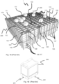
- FIG. 3A Perspective views of an automated storage and retrieval system are shown in Fig. 3A .
- the automated storage and retrieval system comprises a storage grid 104, onto which a plurality of container handling vehicles 200,300 operates, and a delivery system 140 comprising a delivery rail system 50 onto which a plurality of delivery vehicles 30 operates.
- the delivery vehicles 30 are provided with wheel arrangement 31 comprising first and second sets of wheels for driving the delivery vehicles in the first direction (X) and the second direction (Y).
- a master control system 800 keeps track of the container handling vehicles 200,300 operating on the storage grid 104 and the delivery vehicles 30 operating on the delivery rail system 30.
- the delivery system 140 comprises one or more of the delivery vehicles 30 as described above, i.e. delivery vehicles 30 configured to receive and support one or more storage containers 106 for transport between one or more delivery columns 119,120 of the storage grid 104 and one or more predetermined positions outside the storage grid 104.
- the predetermined positions may for example be a second location, a container accessing station, a conveyor line, another storage container, or a transport vehicle such as a truck.
- the delivery system 140 may further comprise a delivery rail system 50 situated below a delivery port of the one or more delivery columns 119,120.
- the delivery rail system 50 may be constructed in the same way or a similar way as the rail system 108 for the container handling vehicles 200,300.
- the delivery rail system 50 may comprise a first set of parallel rails 51 arranged in a horizontal plane (P1) and extending in a first direction (X), and a second set of parallel rails 52 arranged in the horizontal plane (P1) and extending in a second direction (Y) which is orthogonal to the first direction (X).
- the delivery rail system 50 may also be a double rail system, as is shown in Fig. 2B , thus allowing a delivery vehicle 30 having a footprint generally corresponding to the lateral area defined by a delivery grid column to travel along a row of grid columns even if another delivery vehicle 30 is positioned above a grid column neighbouring that row.
- Both the single and double rail system, or a combination comprising a single and double rail arrangement in a single rail system, forms a grid pattern in the horizontal plane P1 comprising a plurality of rectangular and uniform grid locations or grid cells, where each grid cell comprises a grid opening being delimited by a pair of rails of the first rails and a pair of rails of the second set of rails.
- the delivery vehicles 30 comprises a closed bottom portion and are configured to receive storage containers 106 from above (for example from container handling vehicles 200,300 operating on storage grid 104 at a level above the delivery system 140 where the delivery vehicles 30 operate).
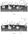
- FIGs. 3B and 3C show two examples where fume, smoke or heat emission 400 has occurred on a storage grid 104 in an automated storage and retrieval system 1.
- a plurality of container handling vehicles 200, 200' operates on a rail system 108 of a storage grid 104 in an automated storage and retrieval system 1 and communicates with a master control system 800.
- Some of the container handling vehicles 200, 200' have been equipped with fire detection device 150.
- a majority, preferably above 50%, of the container handling vehicles 200, 200' comprises a fire detection device 150, possibly together with stationary fire detection devices 150 arranged on the storage grid 104.
- the delivery vehicles 30 operating on a delivery rail system 50 of a delivery system 140 like the one in Fig. 3A may also be equipped with, or comprise, fire detection device(s) 150 in order to detect any fume, smoke or heat emission 400 within the delivery system 140, possibly together with stationary fire detection devices 150 arranged on the delivery system 140.
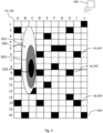
- Fig. 4 shows an example of a heat map created by the master control system based on input from a plurality of fire detection devices 150 arranged on container handling vehicles 200,300.
- fire detection devices 150 may also be arranged on delivery vehicles 30 such that a similar heat map ay be created based on data from the fire detection device from fire detection devices 150 on delivery vehicles 30.
- Order for the master control system 800 to provide the heat map 160 preferably three or more fire detection devices 150 which can provide additional input to the master control system 800 with regards to concentration of fume or smoke, or in case of heat detection, additional input from e.g. an infra-red camera or temperature sensor on the container handling vehicle 200',200 x , are utilized.
- the master control system 800 can create a heat map 160 which indicates the probable location of the source of the fume, smoke or heat emission (see Figs. 3B and 3C ).
- the disclosed heat map 160 comprises an outer portion 161 indicated by coarse-grains, an intermediate portion 161 indicated by stripes and an inner portion 162 indicated by solid black.
- the heat map 160 may indicated that it is certain that the source of the fume, smoke or heat emission 400 is within the outer portion 161, and almost certain that the source of the fume, smoke or heat emission 400 is within the striped portion 161, and very likely that the source of the fume, smoke or heat emission 400 is within the inner portion 162. If the master control system 800 has drawn up such a heat map 160, it is most promising for any fire-fighting crew to focus their initial fire-fighting in the inner portion 162 (i.e. within cell locations B7-B10 and C7-C10) on Fig. 4 . Although the figure is shown in relation to container handling vehicles on a storage grid, a similar figure may be made based on input from fire detection devices arranged on delivery vehicles operating on a delivery rail.
- Fig. 5 is a flow-chart of an example of steps to be taken in the event a container handling vehicle or delivery vehicle detects fume, smoke or heat. Such a process may include the following steps:
- Figs. 6A-6D are sequential step-by-step illustrations of the flow-chart of Fig. 5 , where one and one container handling vehicle 200' ...x with a fire detection device is instructed to drive to grid cells close to a container handling vehicle 200' that has detected fume, smoke or heat 400 in order for the master control system 800 to process data from the fire detection device received from the container handing vehicles 200' ...x to predict location of the source of the fume, smoke or heat 400.
- a first container handling vehicle 200' in cell H5 which first container handling vehicle 200' is provided with a fire detection device (not shown in Fig. 6A ), detects fume, smoke or heat 400.
- the first container handling vehicle 200' transmits data from the fire detection device to master control system 800.
- the master control system 800 keeps continuous track of all of the container handling vehicles 200' ...x , and thus know the position of the first container handling vehicle 200' which has detected fume, smoke or heat 400.
- the master control system 800 processes the data from the fire detection device received data from the fire detection device received from the first container handling vehicle 200'.
- the master control system 800 based on the input from the first container handling vehicle 200', has instructed a second container handling vehicle 200" initially positioned in cell E3, to move to cell G3 (as illustrated by arrow AR-1) which is closer to the first container handling vehicle 200' (and expected to be closer to the source of the fume, smoke or heat emission 400).
- cell G3 as illustrated by arrow AR-1
- the fire detection device of the second container handling vehicle 200" transmits data from the fire detection device to the master control system 800.
- the master control system 800 processes data from the fire detection device from the first and second container handling vehicles 200', 200".
- the master control system 800 based on the input from the first and second container handling vehicles 200', 200", has instructed a third container handling vehicle 200'" initially positioned in cell F8, to move to cell F6 (as illustrated by arrow AR-2) which is closer to the first and second container handling vehicles 200', 200" (and expected to be closer to the source of the fume, smoke or heat emission 400).
- cell F6 as illustrated by arrow AR-2
- the fire detection device of the third container handling vehicle 200'" transmits data from the fire detection device to the master control system 800.
- the master control system 800 processes data from the fire detection device from the first, second and third container handling vehicles 200', 200", 200'".
- the master control system 800 based on the processing has a reasonable prediction on the location of the source of the fume, smoke or heat 400, no further container handling vehicles 200 x are instructed to move closer to the expected source of the fume, smoke or heat emission 400.
- arranging three container handling vehicles 200', 200", 200'" in a triangular arrangement TA enclosing the source of the fume, smoke or heat emission 400 will be sufficient in order to establish a reasonable prediction on location of the source for the fume, smoke or heat emission 400 is.
- the master control system 800 based on the input from the first, second and third container handling vehicles 200', 200", 200′′′, has instructed a fourth container handling vehicle 200'''' initially positioned in cell 11, to move to cell J3 (as illustrated by arrow AR-3) which is closer to the first, second and or third container handling vehicles 200', 200", 200'" (and expected to be closer to the source of the fume, smoke or heat emission 400).
- cell J3 as illustrated by arrow AR-3
- the fire detection device of the fourth container handling vehicle 200''''' transmits data from the fire detection device to the master control system 800.
- the master control system 800 processes data from the fire detection devices from the first, second, third container handling vehicles 200', 200", 200'", 200"".
- a total of four container handling vehicles 200', 200", 200'", 200"” are arranged as a four-cornered polygon PA enclosing the source of the fume, smoke or heat emission 400.
- This setup is almost certainly enough to establish a reasonable location for the source of the fume, smoke or heat emission 400.
- the master control system 800 may instruct further container handling vehicles 200 x with fire detection device to move closer to the expected location of the source of the fume, smoke or heat emission 400.
Landscapes
- Engineering & Computer Science (AREA)
- Business, Economics & Management (AREA)
- Human Resources & Organizations (AREA)
- Physics & Mathematics (AREA)
- General Physics & Mathematics (AREA)
- Operations Research (AREA)
- Economics (AREA)
- Strategic Management (AREA)
- Entrepreneurship & Innovation (AREA)
- Emergency Management (AREA)
- Mechanical Engineering (AREA)
- Health & Medical Sciences (AREA)
- Public Health (AREA)
- Theoretical Computer Science (AREA)
- General Business, Economics & Management (AREA)
- Development Economics (AREA)
- Marketing (AREA)
- Quality & Reliability (AREA)
- Tourism & Hospitality (AREA)
- Remote Sensing (AREA)
- Aviation & Aerospace Engineering (AREA)
- Automation & Control Theory (AREA)
- Radar, Positioning & Navigation (AREA)
- Educational Administration (AREA)
- Game Theory and Decision Science (AREA)
- Analytical Chemistry (AREA)
- Computing Systems (AREA)
- Chemical & Material Sciences (AREA)
- Mathematical Physics (AREA)
- Warehouses Or Storage Devices (AREA)
- Fire Alarms (AREA)
- Alarm Systems (AREA)
Applications Claiming Priority (3)
| Application Number | Priority Date | Filing Date | Title |
|---|---|---|---|
| NO20190546A NO20190546A1 (en) | 2019-04-25 | 2019-04-25 | An automated storage and retrieval system with fire detection device and methods of locating and/or verifying fire or smoke in an automated storage and retrieval system |
| PCT/EP2020/059819 WO2020216608A1 (en) | 2019-04-25 | 2020-04-06 | An automated storage and retrieval system with fire detection device and methods of locating and/or verifying fire or smoke in an automated storage and retrieval system |
| EP20717185.1A EP3959673B1 (de) | 2019-04-25 | 2020-04-06 | Automatisiertes regalbedienungssystem mit feuerdetektionsvorrichtung und verfahren zum lokalisieren und/oder überprüfen von feuer oder rauch in einem automatischen regalbedienungssystem |
Related Parent Applications (1)
| Application Number | Title | Priority Date | Filing Date |
|---|---|---|---|
| EP20717185.1A Division EP3959673B1 (de) | 2019-04-25 | 2020-04-06 | Automatisiertes regalbedienungssystem mit feuerdetektionsvorrichtung und verfahren zum lokalisieren und/oder überprüfen von feuer oder rauch in einem automatischen regalbedienungssystem |
Publications (2)
| Publication Number | Publication Date |
|---|---|
| EP4480859A2 true EP4480859A2 (de) | 2024-12-25 |
| EP4480859A3 EP4480859A3 (de) | 2025-03-19 |
Family
ID=70189974
Family Applications (2)
| Application Number | Title | Priority Date | Filing Date |
|---|---|---|---|
| EP24196585.4A Pending EP4480859A3 (de) | 2019-04-25 | 2020-04-06 | Automatisiertes regalbedienungssystem mit branderkennungsvorrichtung und verfahren zur ortung und/oder überprüfung von feuer oder rauch in einem automatisierten regalbedienungssystem |
| EP20717185.1A Active EP3959673B1 (de) | 2019-04-25 | 2020-04-06 | Automatisiertes regalbedienungssystem mit feuerdetektionsvorrichtung und verfahren zum lokalisieren und/oder überprüfen von feuer oder rauch in einem automatischen regalbedienungssystem |
Family Applications After (1)
| Application Number | Title | Priority Date | Filing Date |
|---|---|---|---|
| EP20717185.1A Active EP3959673B1 (de) | 2019-04-25 | 2020-04-06 | Automatisiertes regalbedienungssystem mit feuerdetektionsvorrichtung und verfahren zum lokalisieren und/oder überprüfen von feuer oder rauch in einem automatischen regalbedienungssystem |
Country Status (10)
| Country | Link |
|---|---|
| US (2) | US12409352B2 (de) |
| EP (2) | EP4480859A3 (de) |
| JP (2) | JP7576045B2 (de) |
| KR (1) | KR20220005490A (de) |
| CN (2) | CN120504075A (de) |
| CA (1) | CA3134456A1 (de) |
| ES (1) | ES2991608T3 (de) |
| NO (1) | NO20190546A1 (de) |
| PL (1) | PL3959673T3 (de) |
| WO (1) | WO2020216608A1 (de) |
Families Citing this family (5)
| Publication number | Priority date | Publication date | Assignee | Title |
|---|---|---|---|---|
| US11498757B2 (en) | 2018-06-12 | 2022-11-15 | Autostore Technology AS | Storage system |
| EP3807180B1 (de) | 2018-06-12 | 2023-09-20 | Autostore Technology AS | Behälterzugriffsstation mit hebevorrichtung |
| NO345896B1 (en) * | 2020-01-31 | 2021-10-04 | Autostore Tech As | System and method for performing measurements while containers are being handled by container handling vehicles |
| GB202117095D0 (en) * | 2021-11-26 | 2022-01-12 | Ocado Innovation Ltd | Determining an exclusion zone in a workspace of transport devices |
| MY208255A (en) * | 2023-05-16 | 2025-04-29 | Pingspace Sdn Bhd | An automated storage system |
Citations (5)
| Publication number | Priority date | Publication date | Assignee | Title |
|---|---|---|---|---|
| NO317366B1 (no) | 1999-07-01 | 2004-10-18 | Autostore As | Lagringsanlegg med fjernstyrte vogner med to hjulsett og heisinnretning for drift på skinner anlagt i kryss over kolonner av lagringsenheter som er adskilt med vertikale profilstolper |
| WO2014075937A1 (en) | 2012-11-13 | 2014-05-22 | Jakob Hatteland Logistics As | Storage system |
| WO2014090684A1 (en) | 2012-12-10 | 2014-06-19 | Jakob Hatteland Logistics As | Robot for transporting storage bins |
| WO2015193278A1 (en) | 2014-06-19 | 2015-12-23 | Jakob Hatteland Logistics As | Robot for transporting storage bins |
| WO2016198467A1 (en) | 2015-06-08 | 2016-12-15 | Ocado Innovation Limited | Object storage, handling, and retrieving system and method |
Family Cites Families (18)
| Publication number | Priority date | Publication date | Assignee | Title |
|---|---|---|---|---|
| JPS61276573A (ja) * | 1985-05-29 | 1986-12-06 | ホーチキ株式会社 | 自動消火装置 |
| JPH09221201A (ja) * | 1996-02-20 | 1997-08-26 | Mitsubishi Heavy Ind Ltd | 消火機能付きスタッカクレーン |
| JP3123424B2 (ja) * | 1996-02-20 | 2001-01-09 | 鹿島建設株式会社 | 立体自動倉庫の自動消火方法および自動消火パレット |
| JP2002260117A (ja) * | 2001-03-06 | 2002-09-13 | Hatsuta Seisakusho Co Ltd | 立体駐車場等の火災感知システム |
| CN100425959C (zh) * | 2003-07-25 | 2008-10-15 | 陈伟 | 一种对红外源热映象进行检测的方法 |
| CN202189434U (zh) * | 2011-08-24 | 2012-04-11 | 黄剑锋 | 一种基于红外热成像技术的智能火情侦察仪 |
| KR20250022901A (ko) * | 2015-04-15 | 2025-02-17 | 오카도 이노베이션 리미티드 | 보관 시스템 및 방법 |
| JP2018513379A (ja) * | 2015-04-21 | 2018-05-24 | フィリップス ライティング ホールディング ビー ヴィ | 温度異常の特定 |
| CN107635891B (zh) * | 2015-06-09 | 2021-06-04 | 盖特法布瑞克有限公司 | 机器人库存处理 |
| GB201603518D0 (en) * | 2016-02-29 | 2016-04-13 | Ocado Innovation Ltd | Robotic fire extinguishing device and handling method |
| GB201610837D0 (en) * | 2016-06-21 | 2016-08-03 | Ocado Innovation Ltd | Robotic cargo handling system and method |
| DE102016212645B4 (de) * | 2016-07-12 | 2018-06-14 | Minimax Gmbh & Co. Kg | Unbemanntes Fahrzeug, System und Verfahren zur Einleitung einer Brandlöschaktion |
| JP2018114229A (ja) * | 2017-01-20 | 2018-07-26 | 株式会社ダイフク | 物品搬送設備 |
| NO345224B1 (en) * | 2017-05-08 | 2020-11-09 | Autostore Tech As | Container handling vehicle for picking up storage containers in an automated storage and retrieval system and a method of operating such a system. |
| US20190022441A1 (en) * | 2017-07-20 | 2019-01-24 | Carrier Corporation | Portable fire detection and suppression vehicle |
| CN107341947A (zh) * | 2017-07-21 | 2017-11-10 | 华南理工大学 | 一种基于红外热像仪的火灾报警器及火灾报警方法 |
| WO2019094511A1 (en) * | 2017-11-07 | 2019-05-16 | Nordstrom, Inc. | Systems and methods for storage, retrieval, and sortation in supply chain |
| CN109230148A (zh) * | 2018-08-02 | 2019-01-18 | 李丹 | 基于机器人的无人化智能仓储系统 |
-
2019
- 2019-04-25 NO NO20190546A patent/NO20190546A1/en unknown
-
2020
- 2020-04-06 CN CN202510674395.1A patent/CN120504075A/zh active Pending
- 2020-04-06 ES ES20717185T patent/ES2991608T3/es active Active
- 2020-04-06 JP JP2021563016A patent/JP7576045B2/ja active Active
- 2020-04-06 EP EP24196585.4A patent/EP4480859A3/de active Pending
- 2020-04-06 EP EP20717185.1A patent/EP3959673B1/de active Active
- 2020-04-06 PL PL20717185.1T patent/PL3959673T3/pl unknown
- 2020-04-06 US US17/605,432 patent/US12409352B2/en active Active
- 2020-04-06 CN CN202080030937.7A patent/CN113728343B/zh active Active
- 2020-04-06 CA CA3134456A patent/CA3134456A1/en active Pending
- 2020-04-06 WO PCT/EP2020/059819 patent/WO2020216608A1/en not_active Ceased
- 2020-04-06 KR KR1020217037354A patent/KR20220005490A/ko not_active Ceased
-
2024
- 2024-09-13 JP JP2024159023A patent/JP2024169483A/ja active Pending
-
2025
- 2025-08-19 US US19/304,410 patent/US20250371955A1/en active Pending
Patent Citations (5)
| Publication number | Priority date | Publication date | Assignee | Title |
|---|---|---|---|---|
| NO317366B1 (no) | 1999-07-01 | 2004-10-18 | Autostore As | Lagringsanlegg med fjernstyrte vogner med to hjulsett og heisinnretning for drift på skinner anlagt i kryss over kolonner av lagringsenheter som er adskilt med vertikale profilstolper |
| WO2014075937A1 (en) | 2012-11-13 | 2014-05-22 | Jakob Hatteland Logistics As | Storage system |
| WO2014090684A1 (en) | 2012-12-10 | 2014-06-19 | Jakob Hatteland Logistics As | Robot for transporting storage bins |
| WO2015193278A1 (en) | 2014-06-19 | 2015-12-23 | Jakob Hatteland Logistics As | Robot for transporting storage bins |
| WO2016198467A1 (en) | 2015-06-08 | 2016-12-15 | Ocado Innovation Limited | Object storage, handling, and retrieving system and method |
Also Published As
| Publication number | Publication date |
|---|---|
| EP4480859A3 (de) | 2025-03-19 |
| US12409352B2 (en) | 2025-09-09 |
| KR20220005490A (ko) | 2022-01-13 |
| CN113728343B (zh) | 2025-06-06 |
| JP7576045B2 (ja) | 2024-10-30 |
| US20250371955A1 (en) | 2025-12-04 |
| EP3959673C0 (de) | 2024-08-28 |
| CN120504075A (zh) | 2025-08-19 |
| CA3134456A1 (en) | 2020-10-29 |
| WO2020216608A1 (en) | 2020-10-29 |
| PL3959673T3 (pl) | 2025-01-20 |
| EP3959673B1 (de) | 2024-08-28 |
| EP3959673A1 (de) | 2022-03-02 |
| JP2024169483A (ja) | 2024-12-05 |
| NO20190546A1 (en) | 2020-10-26 |
| CN113728343A (zh) | 2021-11-30 |
| US20220241627A1 (en) | 2022-08-04 |
| ES2991608T3 (es) | 2024-12-04 |
| JP2022530410A (ja) | 2022-06-29 |
Similar Documents
| Publication | Publication Date | Title |
|---|---|---|
| EP3959673B1 (de) | Automatisiertes regalbedienungssystem mit feuerdetektionsvorrichtung und verfahren zum lokalisieren und/oder überprüfen von feuer oder rauch in einem automatischen regalbedienungssystem | |
| EP4025524B1 (de) | Verfahren und system zur bereitstellung eines bedienerzugriffs auf eine zielspeicherposition in einem automatischen regalbedienungssystem | |
| US12286295B2 (en) | Robot position detection system | |
| US20250050145A1 (en) | Automated grid storage and retrieval system with passive fire prevention arrangement | |
| US12503315B2 (en) | System and method for detection of anomalies in the tracks on a three-dimensional storage system | |
| HK40055055A (en) | An automated storage and retrieval system with fire detection device and methods of locating and/or verifying fire or smoke in an automated storage and retrieval system | |
| HK40055055B (zh) | 具有火灾探测装置的自动化仓储系统以及在自动化仓储系统中定位和/或验证火灾或烟雾的方法 | |
| HK40063202B (en) | Method, and associated system, of providing an operator access to a target storage position in an automated storage and retrieval system | |
| HK40063202A (en) | Method, and associated system, of providing an operator access to a target storage position in an automated storage and retrieval system | |
| HK40090188A (zh) | 用於自动化仓储系统的主控制系统 | |
| HK40077781A (en) | A remotely operated vehicle with an arrangement to provide a pre-alert and tracking of a position of the vehicle |
Legal Events
| Date | Code | Title | Description |
|---|---|---|---|
| PUAI | Public reference made under article 153(3) epc to a published international application that has entered the european phase |
Free format text: ORIGINAL CODE: 0009012 |
|
| STAA | Information on the status of an ep patent application or granted ep patent |
Free format text: STATUS: THE APPLICATION HAS BEEN PUBLISHED |
|
| STAA | Information on the status of an ep patent application or granted ep patent |
Free format text: STATUS: REQUEST FOR EXAMINATION WAS MADE |
|
| AC | Divisional application: reference to earlier application |
Ref document number: 3959673 Country of ref document: EP Kind code of ref document: P |
|
| AK | Designated contracting states |
Kind code of ref document: A2 Designated state(s): AL AT BE BG CH CY CZ DE DK EE ES FI FR GB GR HR HU IE IS IT LI LT LU LV MC MK MT NL NO PL PT RO RS SE SI SK SM TR |
|
| 17P | Request for examination filed |
Effective date: 20241210 |
|
| REG | Reference to a national code |
Ref country code: DE Ref legal event code: R079 Free format text: PREVIOUS MAIN CLASS: B65G0001040000 Ipc: G06Q0010060000 |
|
| PUAL | Search report despatched |
Free format text: ORIGINAL CODE: 0009013 |
|
| AK | Designated contracting states |
Kind code of ref document: A3 Designated state(s): AL AT BE BG CH CY CZ DE DK EE ES FI FR GB GR HR HU IE IS IT LI LT LU LV MC MK MT NL NO PL PT RO RS SE SI SK SM TR |
|
| RIC1 | Information provided on ipc code assigned before grant |
Ipc: G06Q 10/08 20240101ALI20250211BHEP Ipc: B65G 1/04 20060101ALI20250211BHEP Ipc: A62C 3/00 20060101ALI20250211BHEP Ipc: G06Q 10/06 20230101AFI20250211BHEP |
|
| STAA | Information on the status of an ep patent application or granted ep patent |
Free format text: STATUS: EXAMINATION IS IN PROGRESS |
|
| 17Q | First examination report despatched |
Effective date: 20260309 |
|
| RAP3 | Party data changed (applicant data changed or rights of an application transferred) |
Owner name: AUTOSTORE TECHNOLOGY AS |