EP4480453A2 - Herzklappenstützvorrichtung und verfahren zur herstellung und verwendung davon - Google Patents
Herzklappenstützvorrichtung und verfahren zur herstellung und verwendung davon Download PDFInfo
- Publication number
- EP4480453A2 EP4480453A2 EP24197322.1A EP24197322A EP4480453A2 EP 4480453 A2 EP4480453 A2 EP 4480453A2 EP 24197322 A EP24197322 A EP 24197322A EP 4480453 A2 EP4480453 A2 EP 4480453A2
- Authority
- EP
- European Patent Office
- Prior art keywords
- anchoring
- arms
- end region
- arm
- flow optimizer
- Prior art date
- Legal status (The legal status is an assumption and is not a legal conclusion. Google has not performed a legal analysis and makes no representation as to the accuracy of the status listed.)
- Pending
Links
Images


Classifications
-
- A—HUMAN NECESSITIES
- A61—MEDICAL OR VETERINARY SCIENCE; HYGIENE
- A61F—FILTERS IMPLANTABLE INTO BLOOD VESSELS; PROSTHESES; DEVICES PROVIDING PATENCY TO, OR PREVENTING COLLAPSING OF, TUBULAR STRUCTURES OF THE BODY, e.g. STENTS; ORTHOPAEDIC, NURSING OR CONTRACEPTIVE DEVICES; FOMENTATION; TREATMENT OR PROTECTION OF EYES OR EARS; BANDAGES, DRESSINGS OR ABSORBENT PADS; FIRST-AID KITS
- A61F2/00—Filters implantable into blood vessels; Prostheses, i.e. artificial substitutes or replacements for parts of the body; Appliances for connecting them with the body; Devices providing patency to, or preventing collapsing of, tubular structures of the body, e.g. stents
- A61F2/02—Prostheses implantable into the body
- A61F2/24—Heart valves ; Vascular valves, e.g. venous valves; Heart implants, e.g. passive devices for improving the function of the native valve or the heart muscle; Transmyocardial revascularisation [TMR] devices; Valves implantable in the body
- A61F2/2409—Support rings therefor, e.g. for connecting valves to tissue
-
- A—HUMAN NECESSITIES
- A61—MEDICAL OR VETERINARY SCIENCE; HYGIENE
- A61F—FILTERS IMPLANTABLE INTO BLOOD VESSELS; PROSTHESES; DEVICES PROVIDING PATENCY TO, OR PREVENTING COLLAPSING OF, TUBULAR STRUCTURES OF THE BODY, e.g. STENTS; ORTHOPAEDIC, NURSING OR CONTRACEPTIVE DEVICES; FOMENTATION; TREATMENT OR PROTECTION OF EYES OR EARS; BANDAGES, DRESSINGS OR ABSORBENT PADS; FIRST-AID KITS
- A61F2/00—Filters implantable into blood vessels; Prostheses, i.e. artificial substitutes or replacements for parts of the body; Appliances for connecting them with the body; Devices providing patency to, or preventing collapsing of, tubular structures of the body, e.g. stents
- A61F2/02—Prostheses implantable into the body
- A61F2/24—Heart valves ; Vascular valves, e.g. venous valves; Heart implants, e.g. passive devices for improving the function of the native valve or the heart muscle; Transmyocardial revascularisation [TMR] devices; Valves implantable in the body
- A61F2/2412—Heart valves ; Vascular valves, e.g. venous valves; Heart implants, e.g. passive devices for improving the function of the native valve or the heart muscle; Transmyocardial revascularisation [TMR] devices; Valves implantable in the body with soft flexible valve members, e.g. tissue valves shaped like natural valves
- A61F2/2415—Manufacturing methods
-
- A—HUMAN NECESSITIES
- A61—MEDICAL OR VETERINARY SCIENCE; HYGIENE
- A61F—FILTERS IMPLANTABLE INTO BLOOD VESSELS; PROSTHESES; DEVICES PROVIDING PATENCY TO, OR PREVENTING COLLAPSING OF, TUBULAR STRUCTURES OF THE BODY, e.g. STENTS; ORTHOPAEDIC, NURSING OR CONTRACEPTIVE DEVICES; FOMENTATION; TREATMENT OR PROTECTION OF EYES OR EARS; BANDAGES, DRESSINGS OR ABSORBENT PADS; FIRST-AID KITS
- A61F2/00—Filters implantable into blood vessels; Prostheses, i.e. artificial substitutes or replacements for parts of the body; Appliances for connecting them with the body; Devices providing patency to, or preventing collapsing of, tubular structures of the body, e.g. stents
- A61F2/02—Prostheses implantable into the body
- A61F2/24—Heart valves ; Vascular valves, e.g. venous valves; Heart implants, e.g. passive devices for improving the function of the native valve or the heart muscle; Transmyocardial revascularisation [TMR] devices; Valves implantable in the body
- A61F2/2412—Heart valves ; Vascular valves, e.g. venous valves; Heart implants, e.g. passive devices for improving the function of the native valve or the heart muscle; Transmyocardial revascularisation [TMR] devices; Valves implantable in the body with soft flexible valve members, e.g. tissue valves shaped like natural valves
- A61F2/2418—Scaffolds therefor, e.g. support stents
-
- A—HUMAN NECESSITIES
- A61—MEDICAL OR VETERINARY SCIENCE; HYGIENE
- A61F—FILTERS IMPLANTABLE INTO BLOOD VESSELS; PROSTHESES; DEVICES PROVIDING PATENCY TO, OR PREVENTING COLLAPSING OF, TUBULAR STRUCTURES OF THE BODY, e.g. STENTS; ORTHOPAEDIC, NURSING OR CONTRACEPTIVE DEVICES; FOMENTATION; TREATMENT OR PROTECTION OF EYES OR EARS; BANDAGES, DRESSINGS OR ABSORBENT PADS; FIRST-AID KITS
- A61F2/00—Filters implantable into blood vessels; Prostheses, i.e. artificial substitutes or replacements for parts of the body; Appliances for connecting them with the body; Devices providing patency to, or preventing collapsing of, tubular structures of the body, e.g. stents
- A61F2/02—Prostheses implantable into the body
- A61F2/24—Heart valves ; Vascular valves, e.g. venous valves; Heart implants, e.g. passive devices for improving the function of the native valve or the heart muscle; Transmyocardial revascularisation [TMR] devices; Valves implantable in the body
- A61F2/2442—Annuloplasty rings or inserts for correcting the valve shape; Implants for improving the function of a native heart valve
- A61F2/246—Devices for obstructing a leak through a native valve in a closed condition
-
- A—HUMAN NECESSITIES
- A61—MEDICAL OR VETERINARY SCIENCE; HYGIENE
- A61F—FILTERS IMPLANTABLE INTO BLOOD VESSELS; PROSTHESES; DEVICES PROVIDING PATENCY TO, OR PREVENTING COLLAPSING OF, TUBULAR STRUCTURES OF THE BODY, e.g. STENTS; ORTHOPAEDIC, NURSING OR CONTRACEPTIVE DEVICES; FOMENTATION; TREATMENT OR PROTECTION OF EYES OR EARS; BANDAGES, DRESSINGS OR ABSORBENT PADS; FIRST-AID KITS
- A61F2/00—Filters implantable into blood vessels; Prostheses, i.e. artificial substitutes or replacements for parts of the body; Appliances for connecting them with the body; Devices providing patency to, or preventing collapsing of, tubular structures of the body, e.g. stents
- A61F2/02—Prostheses implantable into the body
- A61F2/24—Heart valves ; Vascular valves, e.g. venous valves; Heart implants, e.g. passive devices for improving the function of the native valve or the heart muscle; Transmyocardial revascularisation [TMR] devices; Valves implantable in the body
- A61F2/2427—Devices for manipulating or deploying heart valves during implantation
- A61F2/2436—Deployment by retracting a sheath
-
- A—HUMAN NECESSITIES
- A61—MEDICAL OR VETERINARY SCIENCE; HYGIENE
- A61F—FILTERS IMPLANTABLE INTO BLOOD VESSELS; PROSTHESES; DEVICES PROVIDING PATENCY TO, OR PREVENTING COLLAPSING OF, TUBULAR STRUCTURES OF THE BODY, e.g. STENTS; ORTHOPAEDIC, NURSING OR CONTRACEPTIVE DEVICES; FOMENTATION; TREATMENT OR PROTECTION OF EYES OR EARS; BANDAGES, DRESSINGS OR ABSORBENT PADS; FIRST-AID KITS
- A61F2/00—Filters implantable into blood vessels; Prostheses, i.e. artificial substitutes or replacements for parts of the body; Appliances for connecting them with the body; Devices providing patency to, or preventing collapsing of, tubular structures of the body, e.g. stents
- A61F2/02—Prostheses implantable into the body
- A61F2/24—Heart valves ; Vascular valves, e.g. venous valves; Heart implants, e.g. passive devices for improving the function of the native valve or the heart muscle; Transmyocardial revascularisation [TMR] devices; Valves implantable in the body
- A61F2/2442—Annuloplasty rings or inserts for correcting the valve shape; Implants for improving the function of a native heart valve
- A61F2/2466—Delivery devices therefor
-
- A—HUMAN NECESSITIES
- A61—MEDICAL OR VETERINARY SCIENCE; HYGIENE
- A61F—FILTERS IMPLANTABLE INTO BLOOD VESSELS; PROSTHESES; DEVICES PROVIDING PATENCY TO, OR PREVENTING COLLAPSING OF, TUBULAR STRUCTURES OF THE BODY, e.g. STENTS; ORTHOPAEDIC, NURSING OR CONTRACEPTIVE DEVICES; FOMENTATION; TREATMENT OR PROTECTION OF EYES OR EARS; BANDAGES, DRESSINGS OR ABSORBENT PADS; FIRST-AID KITS
- A61F2210/00—Particular material properties of prostheses classified in groups A61F2/00 - A61F2/26 or A61F2/82 or A61F9/00 or A61F11/00 or subgroups thereof
- A61F2210/0014—Particular material properties of prostheses classified in groups A61F2/00 - A61F2/26 or A61F2/82 or A61F9/00 or A61F11/00 or subgroups thereof using shape memory or superelastic materials, e.g. nitinol
-
- A—HUMAN NECESSITIES
- A61—MEDICAL OR VETERINARY SCIENCE; HYGIENE
- A61F—FILTERS IMPLANTABLE INTO BLOOD VESSELS; PROSTHESES; DEVICES PROVIDING PATENCY TO, OR PREVENTING COLLAPSING OF, TUBULAR STRUCTURES OF THE BODY, e.g. STENTS; ORTHOPAEDIC, NURSING OR CONTRACEPTIVE DEVICES; FOMENTATION; TREATMENT OR PROTECTION OF EYES OR EARS; BANDAGES, DRESSINGS OR ABSORBENT PADS; FIRST-AID KITS
- A61F2220/00—Fixations or connections for prostheses classified in groups A61F2/00 - A61F2/26 or A61F2/82 or A61F9/00 or A61F11/00 or subgroups thereof
- A61F2220/0008—Fixation appliances for connecting prostheses to the body
- A61F2220/0016—Fixation appliances for connecting prostheses to the body with sharp anchoring protrusions, e.g. barbs, pins, spikes
Definitions
- the disclosed embodiments relate generally to medical device technology and more particularly, but not exclusively, to heart valve support devices and methods for making and using the same.
- a tricuspid valve is an atrioventricular valve located in the right side of the human heart, between the right atrium (RA) and the right ventricle (RV).
- Anatomy of the TV is constituted of three asymmetrical leaflets, septal, anterior, and posterior, supported by a complex sub-valvular apparatus constituted by the chordae tendineae and the papillary muscles.
- the TV is also in proximity of the tendon of Todaro, where the heart's delicate atrioventricular node is located.
- Regurgitant flow occurs during the systolic phases of the cardiac cycle when the tricuspid valve becomes incompetent.
- the incompetence is mainly caused by the pathology-induced progressive enlargement of the valve's annulus, which prevents the leaflets from reaching full coaptation during systole (or during the systole phase of the cardiac cycle).
- the lack of leaflets coaptation causes the development of a regurgitant orifice within the valve through which blood can reenter the right atrium instead of exiting the right ventricle via the pulmonary valve.
- Tricuspid valve regurgitation can be isolated from or associated to other valvulopathies, and leads to congestive heart failure, with reduced functional cardiovascular capacity and ultimately increased risks of mortality.
- Surgical repair or replacement are the most commonly used techniques for treating this pathology, but the clinical results (e.g. mortality and recurrence) are suboptimal. Also, due to the common presence of several comorbidities in most patients affected by tricuspid regurgitation, the majority is ineligible for surgical repair or replacement because of the high risk correlated with those procedures.
- Transcatheter therapy doesn't require open-heart surgery and could be a viable safer alternative.
- the unique anatomical feature of the tricuspid valve is the main challenge for developing a safe and effective implant.
- the anchoring possibly requires burdening of the adjacent cardiac structure (e.g. superior or inferior vena cava, the atrioventricular node, the coronary sinus, the right coronary artery, the ventricular myocardium).
- the low pressure and output of the hemodynamic flow in the right side of the heart increases the risks of inducing atrioventricular pressure gradient and thrombogenesis.
- the present disclosure relates to heart valve support devices and methods for making and using the same.
- a device for assisting a valve of a heart including:
- the cross sectional area during systole is greater than the cross sectional area during diastole.
- the flow optimizer includes:
- the covering collapses at least partially in a direction of a hemodynamic flow during diastole.
- the frame has a conical shape, the first end regions of the plurality of arms joining at a central axis of the conical shape.
- the conical shape has a base adjacent to a ventricle of the heart and a vertex adjacent to an atrium of the heart.
- the covering includes a plurality of leaflet layers each arranged concentrically about the central axis.
- the plurality of leaflet layers include two or more leaflet layers, the two or more leaflet layers including first and second leaflet layers that at least partially overlap.
- the first and second leaflet layers open to define a gap for hemodynamic flow during diastole.
- the first and second leaflet layer are respectively located proximally and distally from the central axis, an atrium-facing surface of the first leaflet layer overlaps at least partially with a ventricle-facing surface of the second leaflet layer.
- the plurality of leaflet layers include two or more leaflet layers, the two or more leaflet layers including two adjacent leaflet layers that at least partially overlap.
- the two adjacent leaflet layers open to define a gap for hemodynamic flow during diastole.
- the two adjacent leaflet layers include first and second leaflet layer respectively located proximally and distally from the central axis, an atrium-facing surface of the first leaflet layer overlaps at least partially with a ventricle-facing surface of the second leaflet layer.
- the covering inflates at least partially toward native valve leaflets during systole.
- the covering at least partially blocks the regurgitation orifice during systole.
- the anchoring mechanism includes one or more anchoring arms each including a proximal end region joining at a central axis and a distal end region extending from the central axis, the distal end regions of the anchoring arms being configured to be located at commissures of native valve leaflets.
- the distal end region is configured to mate with an annulus of the valve at the commissures.
- each of the one or more anchoring arms is configured to have a range of shape expansion and adapts to a geometry of the annulus of the valve at the commissures.
- the anchoring arms are configured to rotate about the central axis of the anchoring mechanism.
- the one or more anchoring arms rotate about the central axis to match angular distribution of the commissures.
- the one or more anchoring arms include a first anchoring arm, the proximal end region of the first anchoring arm including a cylindrical protrusion aligned with the central axis
- the one or more anchoring arms include a second anchoring arm, the proximal end region of the second anchoring arm is fixedly connected to an inner core enclosed in the cylindrical protrusion and configured to rotate about the central axis relative to the first cylindrical protrusion.
- rotating the inner core relative to the first cylindrical protrusion changes an angle between the first and second anchoring arms.
- the one or more anchoring arms include a third anchoring arm, the proximal end region of the third anchoring arm including a central portion located between the cylindrical protrusion and the inner core and configured to rotate about the central axis relative to the inner core.
- rotating the proximal end region of the third anchoring arm relative to the inner core changes an angle between the second and third anchoring arms.
- the anchoring mechanism includes a locking collar configured to fix relative positions among the one or more anchoring arms.
- the anchoring arms are configured to rotate prior to loading into a catheter, after deployment in the heart via the catheter, or a combination thereof.
- the one or more anchoring arms include three anchoring arms, the distal end region of each of the three anchoring arms being configured to be located at a respective commissure of the native valve leaflets.
- each of the one or more anchoring arms includes an intermediate region between the proximal end region and the distal end region, the intermediate region being configured to rest against an inner supra-annular wall of an atrium.
- the anchoring mechanism includes a height adjustment mechanism configured to individually control a shape of each of the one or more anchoring arms.
- the height adjustment mechanism includes a cable having a proximal end region slidingly connected to a proximal end region of a first anchoring arm of the one or more anchoring arms, the proximal end region of the first anchoring arm being aligned with the central axis, the cable having a distal end region connected to a distally-extending portion of a selected anchoring arm of the one or more anchoring arms.
- the device further includes a shaft connecting the flow optimizer and the anchoring mechanism.
- the shaft is threaded such that rotations of the shaft relative to the anchoring mechanism changes a distance between the flow optimizer and the anchoring mechanism.
- the shaft is threaded such that rotations of the shaft relative to the anchoring mechanism changes a radial orientation of the flow optimizer relative to the anchoring mechanism.
- the anchoring mechanism includes a locking collar configured to fix a relative position between the flow optimizer and the anchoring mechanism.
- the shaft is configured to rotate relative to the anchoring mechanism prior to loading into a catheter, after deployment in the heart via the catheter, or a combination thereof.
- each of the flow optimizer and the anchoring mechanism has a crimped conformation adapted to be loaded in a catheter and a deployed conformation upon deployment in the heart.
- the anchoring mechanism includes an anchoring device coupled to the flow optimizer and configured to anchor to a vena cava.
- the flow optimizer includes an atrial anchor coupled to the flow optimizer and configured to anchor to an atrial wall.
- the flow optimizer includes a ventricular anchor coupled to the flow optimizer and configured to anchor to a ventricular wall.
- an apparatus for implantation including:
- the distal end region is configured to mate with an annulus of the valve at the commissure.
- a method for deploying a device for supporting functions of a valve of a heart including:
- the anchoring mechanism includes one or more anchoring arms each including a proximal end region joining at a central axis and a distal end region extending from the central axis, wherein the opening includes partially opening the one or more anchoring arms.
- the method further includes respectively aligning the one or more anchoring arms with commissures of native valve leaflets of the valve.
- the disclosed embodiments relate to catheter-delivered intracardiac implants for supporting and improving the function of the tricuspid valve.
- a flow optimizer is devised to minimize its cross-sectional area and allows hemodynamic flow around and also through the implant, thus minimizing the potential risk of inducing atrioventricular pressure gradient and thrombogenesis.
- the flow optimizer seals or minimizes the regurgitant orifice and reinstates the efficacy of the tricuspid valve.
- the device's anchoring system doesn't require traumatic interaction with the tricuspid valve, right atrium and right ventricle, and implantation can be achieved with minimal procedural steps.
- anchoring mechanism of the device permits intra-procedural adjustments, under standard imaging techniques (e.g. fluoroscopy, echocardiography), of positioning of the flow optimizer within the native tricuspid valve to allow real-time optimization of the hemodynamic flow across the tricuspid valve.
- standard imaging techniques e.g. fluoroscopy, echocardiography
- the disclosure is devised to increase the efficacy, safety, and procedural success of transcatheter therapy of tricuspid valve regurgitation.
- the present disclosure provides tricuspid valve support devices that can be used to reduce or prevent tricuspid regurgitation (TR).
- TR tricuspid regurgitation
- the devices are capable of adopting a crimped conformation, so that they can be deployed using a standard intravascular catheter, and a deployed conformation within the body.
- the devices have a tricuspid valve flow optimizer that is placed within the lumen of the tricuspid valve.
- the flow optimizer permits diastolic hemodynamic flow from the right atrium into the right ventricle and, during systole, reduces or prevents blood regurgitation from the right ventricle into the right atrium through the regurgitation orifice present in the tricuspid valve of subjects affected by TR.
- the flow optimizer is directly connected to an anchoring structure that engages the tricuspid valve annulus at the commissure of the native leaflets and/or the supra-annular walls of the right atrium.
- the flow optimizer is attached to an anchoring element directly or through an articulating link.
- the articulating link can be configured to adopt and hold a three-dimensional configuration in order to maintain a proper shape and orientation from the anchoring device and within the tricuspid valve lumen.
- the anchoring element can be an intravascular stent configured to anchor the device by a frictional contact within the SVC or IVC, thereby providing support to the flow optimizer from the atrial side and further comprises an atrial support or anchoring structure.
- the anchoring element is frictionally engaged with the inner wall of the right ventricle, preferably at the ventricle apex.
- this latter configuration further comprises an atrial anchoring structure.
- the device, the flow optimizer and/or the anchoring mechanism can be applied to any valve of the heart.
- the device can be at least partially oriented such that two opposite end regions of the device are close to and away from the heart, respectively.
- distal can be a relative term that can refer to the direction or side towards the heart and, more specifically, toward the ventricle apex of the heart.
- the flow optimizer 140 in Fig. 1A is located at the distal end of the vena cava-anchored device, as described in more detail below.
- proximal can be a relative term that can refer to the direction or side away from the heart.
- anchoring stent 110 in Fig. 1A is located at the proximal end of the vena cava-anchored device, as described in more detail below.
- the disclosure provides an implantable tricuspid valve support device that can be delivered and implanted using a catheter.
- the device provides a flow optimizer that is placed within the tricuspid valve to support and improve the hemodynamic function in patients affected by tricuspid regurgitation (TR).
- TR tricuspid regurgitation
- the device seals the coaptation gap between the native leaflets during the systolic phase of the cardiac cycle and allows blood flow from the right atrium to the right ventricle during the diastolic phase of the cardiac cycle.
- the disclosure provides an anchored device. Anchoring can be achieved from the atrial side such as within the superior vena cava (SVC) or the inferior vena cava (IVC), or anchoring can be achieved by supporting the device from within the right ventricle.
- SVC superior vena cava
- IVC inferior vena cava
- the device is anchored only within the right atrium. In other embodiments, the device is anchored within the right atrium, at the commissures of the tricuspid valve annulus, and/or at the supra-annular region of the right atrium.
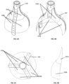
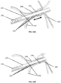
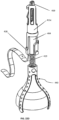
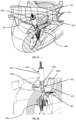
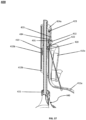
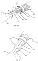
- Fig. 1A illustrates a tricuspid valve support device 100, in a deployed conformation, configured to be anchored in the vena cava.
- the vena cava can include superior vena cava (SVC) and/or inferior vena cava (IVC).
- Fig. 1A shows the device 100 as including an anchoring stent 110 connected to an atrial anchor 130 via an articulating Link 120.
- the atrial anchor 130 is attached to a tricuspid valve flow optimizer 140 and comprises one or more (e.g., one, two, three, four, or more) atrial support arms 135.
- Fig. 1B illustrates an exploded view of these elements in the deployed conformation.
- Fig. 1A illustrates a tricuspid valve support device 100, in a deployed conformation, configured to be anchored in the vena cava.
- the vena cava can include superior vena cava (SVC) and/or inferior vena cava (IVC).
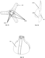
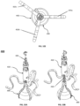
- FIG. 2A illustrates the tricuspid valve support device 100 in a crimped conformation as the tricuspid valve support device 100 can be loaded into an intravascular delivery catheter (not shown).
- Fig. 2B illustrates an exploded view of the tricuspid valve support device 100 in a crimped conformation.
- the anchoring stent 110 serves to anchor the device within the body by a frictional contact with the inner wall of the blood vessel while maintaining vessel patency.
- the anchoring stent 110 can have a generally cylindrical stent body 112.
- the stent body 112 can be attached at a distal end region thereof to the articulating link 120.
- the stent body 112 can be attached at the distal end region thereof to a proximal end region of the articulating link 120 by one or more (e.g., one, two, three, four, or more) Stent Arms 111.
- the articulating link 120 is adapted to connect the anchoring stent 110 to the atrial anchor 130 without significantly impeding blood flow.
- articulating link 120 can be configured to reside toward the center and/or midline of the vessel, when deployed.
- the articulating link 120 can be solid or hollow.
- Articulating link 120 further comprises a Receiver 121 at its distal end that is adapted to receive and secure the atrial anchor 130.
- the Receiver 121 can comprise a first mating pair member adapted to mate with a second mating pair member located on the atrial anchor 130.
- the receiver 121 can be articulating or non-articulating. For embodiments in which the receiver 121 is non-articulating, it is configured to reside entirely within the atrium so that the lack of articulation does not interfere with the proper placement and orientation of the atrial anchor 130 and/or the flow optimizer 140.
- the articulating link 120 is configured to deform and maintain any three-dimensional curvature induced by the catheter delivery system.
- a variety of gooseneck, interlocking coils, and interlocking links can be used in accordance with the principles set forth herein.
- Figs. 17A and 17B illustrate two exemplary types of interlocking links that can be used.
- the atrial anchor 130 comprises a second mating pair member adapted to mate with the first mating pair member located on receiver 121.
- the atrial anchor 130 can include one or more (e.g., one, two, three, four, or more) radially-deploying atrial support arms 135.
- the atrial anchor 130 is adapted to support the flow optimizer 140, on the distal end region of the atrial anchor 130 and within the tricuspid valve (e.g., through the receiver 121).
- the arms 135 are self-deploying from the crimped conformation to the deployed conformation once released from the delivery catheter.
- the arms 135 can be formed from any suitable material, including memory shape materials such as NiTi.
- the arms 135 further comprise a friction enhancing layer on a body-facing surface of the arms 135, in order to enhance adhesion with the atrial wall.
- exemplary friction enhancing layer can be made of polymer including, for example, fabric hook and loop fasteners (for example, Velcro ® available from Velcro company in United Kingdom) and microbarbs.
- the atrial anchor 130 further comprises a height adjustment mechanism adapted to adjust the vertical positioning of the arms 135 relative to the flow optimizer 140.
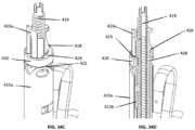
- Fig. 3A illustrates an exemplary height adjustment mechanism defining a channel 131 having a series of notches 132 into which an arm 135 is fitted.
- Fig. 3B provides a close-up view of the vertical positioning system, and
- Fig. 3C provides a cross-sectional view of the interior elements.
- the distal end region of each arm 135 terminates in a tab 136.
- Each arm 135 is slidably engaged with a channel 131 in the receiver 121 such that arm 135 can be translocated in the proximal or distal axial direction.
- Channel 131 defines a series of horizontal notches 132 sized to accept tab 136.
- the arms 135 can be positioned in the deployed conformation, prior to loading the device 100 into the deliver catheter.
- the selection of the height positioning can be determined using imaging and/or other data obtained from the patient.
- the arms 135 can be positioned proximally or distally relative to the flow optimizer 140 after deployment of the device 100 within the atrium.
- the arms 135 can be translocated relative to the flow optimizer 140 using an internal operator-controlled wire that is affixed to the distal end of the arms 135 and adapted to pull the distal end regions of the arms 135 inward towards the central axis of lumen of the device 100, thereby releasing the tabs 136 from the notches 132.
- the arms 135 can be translocated in the axial direction and the spring/memory shape property of the distal ends returns the tabs 136 into the notches 132 when tension from the catheter is released.
- the tabs 136 are reversibly engaged with a wire or tube internal to the catheter lumen in a manner that maintains the tabs 136 disengaged from the notches 132.
- the operator may translocate the arms 135 using that internal wire or tube until the arms 135 are properly positioned within the atrium (e.g., frictionally engaged with the atrial wall), and them disengage the tabs 136 from the internal wire or tube such that the tabs 136 become engaged with the notches 132.
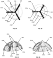
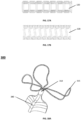
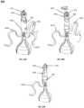
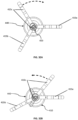
- Fig. 4 shows the tricuspid valve flow optimizer 140 as being in conical in shape.
- the tricuspid valve flow optimizer 140 can be formed in any desirable shape, preferably to match the tricuspid valve anatomy to ensure the atraumatic coaptation during systole of the native tricuspid valve leaflets on the flow optimizer.
- the flow optimizer 140 is devised to coapt with the tricuspid valve leaflets and fill the regurgitation orifice in the tricuspid valve.
- the flow optimizer 140 permits hemodynamic flow from the right atrium into the right ventricle.
- Exemplary flow optimizer 140 can include a frame 145.
- An exemplary frame 145 can be formed from a memory-shape material.
- the frame 145 can include a wire/ribbon frame made from a memory shape material, such as NiTi.
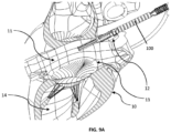
- the exemplary flow optimizer 140 can include a covering formed from one or more (e.g., two, three, four, five, or more) layers of the leaflets 150 (shown in Fig. 5A ).
- the flow optimizer frame can comprise two or more (e.g., two, three, four, five, or more) arms 146 that support the covering material and impart the desired three-dimensional shape to the leaflets 150.
- the leaflets 150 can be made of a material that is impermeable to blood cells and, preferably, impermeable to blood fluids (e.g., aqueous solutions).
- the leaflets 150 can be formed from any suitable biocompatible material including, for example, woven or nonwoven polymer fabrics or sheets, and/or biological tissue harvested from animals (e.g., bovine, porcine, and equine) or humans.
- Suitable biological tissue includes, for example, tissue obtained from the pericardial sac of the donor animal and/or human.
- the leaflets 150 are sutured or attached with other standard fastening methods (e.g. adhesives) on the arms 146 of the frame 145. Additionally and/or alternatively, the leaflets 150 can be molded in the desired three dimensional shape as a single sub-assembly mountable on the frame 145 as shown in Figs. 6E-6F and Fig. 7E .
- the tricuspid valve flow optimizer 140 can be configured to allow the leaflets 150 to collapse towards the center axis of frame 145 during diastole (or during a diastole phase of the cardiac cycle).
- the leaflets 150 of the tricuspid valve flow optimizer 140 are made from a pliable but impermeable material that forms a collapsible dome and/or other three-dimensional structures.
- the atrioventricular hemodynamic pressure gradient opens the tricuspid valve leaflets (not shown).
- the atrioventricular hemodynamic pressure gradient collapses the leaflets 150 of flow optimizer 140 towards the center axis of the frame 145, such that the three-dimensional volume and cross sectional area of the flow optimizer 140 can be reduced as shown in Fig. 5A , thereby allowing blood to flow unrestricted into the ventricle around the flow optimizer 140.
- the cross sectional area of the tricuspid valve flow optimizer 140 can include a size of the tricuspid valve flow optimizer 140 when the tricuspid valve flow optimizer 140 is viewed from the right atrium.
- the tricuspid valve flow optimizer 140 can be configured to inflate towards the arms 146 to fill the lumen of the regurgitation orifice (not shown) and thereby prevents regurgitation during systole.
- systole i.e., ventricular contraction
- the ventricular hemodynamic pressure inflates the leaflets 150 to their full three-dimensional volume which is sufficient to close the tricuspid valve regurgitant orifice and reduce or prevent blood flow into the right atrium.
- the covering of flow optimizer 140 can be formed from an overlapping cascade of two or more (e.g., two, three, four, or more) circumferential leaflet layers of the leaflets 150 to achieve, during the diastolic phase, an efficient reduction of the three-dimensional volume, and to leave open gaps between the leaflet layers of the leaflets 150, allowing a blood flow path throughout the flow optimizer 140.
- the gaps further minimize the cross-section area of the flow optimizer 140 that can restrict the hemodynamic flow, thus reducing the potential of creating a pressure gradient across the native tricuspid valve.
- the gaps also improve blood washout within the flow optimizer, minimizing blood stagnation and thus risk of thrombogenesis.
- the circumferential leaflets are aligned such that the distal (bottom, or the ventricle-side) edge of the upper leaflet layer (closest to the atrium) 150a overlaps on the inside of the proximal (upper, or the atrium-side) edge of the lower leaflet layer (closest to the ventricle) 150b.
- the ventricular pressure closes the leaflets of the tricuspid valve, making the leaflets of the tricuspid valve coapt around the flow optimizer 140, and expands the leaflets layers 150a, 150b to a full three-dimensional shape, pressing the leaflets layers 150a, 150b together to seal gaps 152 (shown in Fig. 7A ), and preventing blood flowing into the ventricle to pass through and around the flow optimizer 140.
- the leaflets layers 150a, 150b of the flow optimizer 140 partially and/or completely collapse, allowing blood flow from the atrium into the ventricle around the flow optimizer 140 and also through the gaps 152 open between the leaflets layers 150a and 150b as shown in Figs. 7A-7D .
- a similar pattern of overlapping three, four or more leaflet layers can be used for each leaflet 150.
- Fig. 8A and Fig. 8C six flaps 250a, 250b, arranged over two levels, allow hemodynamic flow through gaps 254 of the flow optimizer 140 during the diastolic phase of the cardiac cycle.
- the flaps 250a and 250b close the gaps 254 during the systolic phase of the cardiac cycle and thus prevent regurgitation through the native tricuspid valve.
- the flaps 250a, 250b are semi-rigid in order to retain a shape when opening or closing.
- Three flaps 250a are arranged on the upper layer of the frame 248, and three flaps 250b are arranged on the lower layer of the frame.
- the flaps 250a and 250b are connected to the frame 248 of flow optimizer 140 with connection strips 252a, 252b, which are patches of soft tissue or other pliable impermeable material preventing blood passage through the boundaries of flaps 250a and 250b.
- the patches are connected to the frame 248 with hinges 251a, 251b.
- Fig. 8A and Fig. 8C show flow optimizer 140 during the diastolic phase of the cardiac cycle, when the atrioventricular pressure gradient rotates the flaps 250a and 250b about hinges 251a and 251b in the direction of the hemodynamic flow. In this conformation, blood can pass through the open gaps 254 between the flaps 250a and 250b, providing a washing action to prevent risk of blood stagnation and thrombogenesis within the flow optimizer.
- Fig. 8B shows the flow optimizer 140 during the systolic phase of the cardiac cycle, when the atrioventricular pressure gradient rotates the flaps 250a and 250b towards the atrium.
- the distal (closer to the ventricle) edges of the flaps 250b overlap with the proximal (closer to the atrium) edges of the flaps 250a, thus sealing gaps 254 and preventing blood passage through.
- Device 100 can be anchored in the SVC and/or the IVC, depending upon which vessel is accessed. Deployment through the SVC is shown herein. The same principles and techniques can apply to the deployment of device 100 through the IVC.
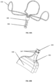
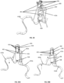
- Figs. 9A-9E illustrate the deployment sequence of device 100 into the heart 10 of a subject (for example, a patient).
- Fig. 9A illustrates that the device is inserted into the right atrium 11 via the SVC 12.
- Device 100 is housed within an intravascular delivery catheter (not shown) which holds device 100 in the crimped conformation.
- Fig. 9B device 100 is deflected toward tricuspid valve 13 using the catheter steering mechanism.
- device 100 can be pushed through into such that the distal end region of device 100 (and catheter) is located within the right ventricle 14.
- the flow optimizer 140 can be deployed as shown in Fig. 9C and device 100 is positioned such that flow optimizer 140 is disposed within tricuspid valve 13.
- the flow optimizer 140 can be deployed by a partial retraction of the catheter.
- the arms 135 can be deployed such that the distal end regions of the arms 135 are seated on the top of tricuspid valve 13 and/or against the wall of atrium 11 so as to suspend flow optimizer 140 within the tricuspid valve 13.
- arms 135 can be height-adjusted as described herein.
- Fig. 9E provides a perspective view of a fully deployed device 100.
- Fig. 10 provides a wire drawing illustrating a fully deployed device 100 within the heart 10.
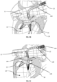
- Fig. 11A illustrates a tricuspid valve support device 200, in a deployed conformation, configured to be anchored in the right ventricle and in the right atrium.
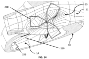
- Fig. 11A shows the device 200 as including a ventricular anchor 210, which can include one or more (e.g., one, two, three, four, or more) support arms 215, connected to an articulating link 220 which is attached to tricuspid valve flow optimizer 240.
- device 200 can further comprise an atrial anchor 230 that can have one or more (e.g., one, two, three, four, or more) arms 235.
- the arms 235 can be radially disposed from a central axis of device 200 and can be single ribbons or rods, or regular geometric or random shapes, as illustrated.
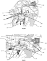
- Fig. 11B illustrates an exploded view of the tricuspid valve support device 200 in the deployed conformation.
- Fig. 12A illustrates the tricuspid valve support device 200 in a crimped conformation as the tricuspid valve support device 200 can be loaded into an intravascular delivery catheter (not shown).
- Fig. 12B illustrates an exploded view of the tricuspid valve support device 200, in a crimped conformation.
- the ventricular anchor 210 is configured and adapted to support device 200 by resting against the inner wall of the right ventricle at and/or near the ventricle apex.
- the ventricular anchor 210 contains a plurality of arms 215 on the distal side.
- the arms 215 can be formed from a memory shape material as described herein such that the arms 215 are self-expanding when released from the intravascular delivery catheter.
- the arms 215 can be formed from any suitable material, including memory shape materials such as NiTi.
- the arms 215 can comprise a friction enhancing layer (e.g., polymer) including, for example, Velcro ® and micro-barbs, in order to enhance adhesion with the ventricular wall. Additionally and/or alternatively, the arms 215 can partially penetrate the ventricular wall in order to facilitate anchoring.
- the ventricular anchor 210 is attached to articulating link 220 on a distal end region of the articulating link 220.
- the articulating link 220 can have similar or the same construction as the articulating link 120, as described above in the context of device 100.
- a tricuspid valve flow optimizer 240 can be attached at a proximal end region of the articulating link 220.
- the tricuspid valve flow optimizer 240 can have the same or similar construction as the tricuspid valve flow optimizer 140, as described above in the context of device 100.
- the tricuspid valve flow optimizer 240 can be supported from the ventricle at the ventricle apex by the articulating link 220 and from the atrium by the atrial anchor 230.
- the flow optimizer 240 and the articulating link 220 can have a height adjustment mechanism to allow for more precise positioning of the flow optimizer 240 within the tricuspid valve.
- the articulating link 220 can have a centrally-disposed non-articulating attachment member 225 defining a plurality of notches 226.
- the flow optimizer 240 comprises a frame 242 having a centrally-disposed sleeve 244 which one or more detents 246 configured to mate with notches 226.
- the flow optimizer 240 positioning can be adjusted by sliding the frame 242 longitudinally along attachment member 225 such that the detents 246 disengage and re-engage with the notches 226.
- the detents 246 are configured to allow sliding in only one direction.
- unidirectional detents 246 are configured to allow translocation in the proximal direction (i.e., toward the ventricle apex).
- the frame 242 and the attachment member 225 have a threaded engagement such that the operator can rotate the frame 242 to cause a translocation in either direction.
- the device 200 can comprises an atrial anchor 230 which extends proximally from the tricuspid valve flow optimizer 240 into the right atrium.
- atrial anchor 230 rests on the inner wall of the right atrium above and/or adjacent to the annulus of the tricuspid valve, to provide additional support and stabilization to the tricuspid valve flow optimizer 240.
- the atrial anchor 230 can comprise one or more (e.g., one, two, three, four, or more) support arms 235.
- the arms 235 can be linear and/or contoured to conform to the atrial wall in and/or adjacent to the supra-annular region of the tricuspid valve.
- the arms 235 can each include a wire that defines a closed shape.
- the atrial anchor 230 and/or the arms 235 are formed from a memory shape material (e.g., NiTi) such that they are self-expanding when released from the delivery catheter.
- the arms 235 can comprise, on the body-facing surface thereof, a friction enhancing layer (e.g., polymer) including, for example, Velcro ® and micro-barbs, in order to enhance adhesion with the atrial wall.
- the atrial anchor 230 can be locked in the desired position relative to the articulating link 220 prior to loading the device 200 into the deliver catheter.
- the selection of the height positioning can be determined using imaging and/or other data obtained from the patient.
- the atrial anchor 230 can be positioned proximally or distally relative to the articulating link 220 after deployment of the ventricular anchor 210 within the ventricle.
- the atrial anchor 230 can be translocated relatively to the articulating link 220 via an internal operator-controlled lumen that is affixed to the central sleeves 244 of the flow optimizer 240.
- a secondary operator-controlled lumen connected to the proximal end of the articulating link 220 and covering the notches 226 can prevent the notches 226 from engaging with the detents 246 of the sleeves 244.
- the secondary operator-controlled lumen can be retrieved to expose the notches 226 thus allowing the detents 246 to engage with the notches 226 and lock the position of the flow optimizer 240 on the articulating link 220.
- device 200 can be deployed using an intravascular catheter (not shown) and delivered through either the SVC or IVC.
- the catheter is pushed through the tricuspid valve from the right atrium into the right ventricle, with the catheter lumen positioned near the ventricle apex.
- the catheter's outer lumen can be partially retracted to deploy the ventricular anchor 210 and/or the arms 215.
- the positioning of device 200 can be adjusted to seat the ventricular anchor 210 at the ventricle apex.
- the catheter's outer lumen can be further retracted, exposing articulating link 220 and the flow optimizer 240.
- the articulating link 220 can be manipulated using the catheter's steerable distal end to seat the flow optimizer 240 at the desired location within the tricuspid valve.
- the catheter's outer lumen can be fully retracted, deploying the atrial anchor 230.
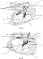
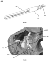
- Fig. 13A is a wireframe drawing showing device 200 fully deployed in the right atrium.
- Fig. 13B is an enlargement illustrating the positioning of the ventricular anchor 210 at the ventricle apex of the right ventricle.
- Fig. 14 is an illustration of a deployed device 200 viewed from the atrial side.
- Fig. 18A illustrates a tricuspid valve support device 300, in a deployed conformation, configured to be anchored in the right atrium.
- Fig. 18A shows the device 300 as including an Atrial Anchor 310.
- the atrial anchor 310 can include one or more (e.g., one, two, three, four, or more) support arms 315, attached to tricuspid valve flow optimizer 340.
- the arms 315 can be radially disposed from the central axis of device 300 and can be single ribbons or rods, or regular geometric or random shapes, as illustrated.
- Fig. 18B illustrates the tricuspid valve support device 300 in a crimped conformation as the tricuspid valve support device 300 can be loaded into an intravascular delivery catheter.
- Fig. 18C illustrates the tricuspid valve support device 300 including an optional vertical height adjustment mechanism to vary the relative distance between the flow optimizer 340 and the atrial anchor 310.
- the tricuspid valve flow optimizer 340 can have the same or similar construction as the tricuspid valve flow optimizer 140, as described above in the context of device 100.
- the tricuspid valve flow optimizer 340 can be supported from a proximal direction by the atrial anchor 310.
- Device 300 further comprises an atrial anchor 310 which extends proximally from the tricuspid valve flow optimizer 340 into the right atrium.
- the atrial anchor 310 rests on the inner wall of the right atrium above and/or adjacent to the annulus of the tricuspid valve to provide support and stabilization to the tricuspid valve flow optimizer 340.
- the atrial anchor 310 can comprise one or more (e.g., one, two, three, four, or more) support arms 315.
- the arms 315 can be linear and/or contoured to conform to the atrial wall in and/or adjacent to the supra-annular region of the tricuspid valve, and they can have individual shapes and/or length.
- the arms 315 can include a wire that defines a closed shape, for example a looped shape.
- the atrial anchor 310 and/or the arms 315 are formed from a memory shape material (e.g., NiTi) such that the atrial anchor 310 and/or the arms 315 are self-expanding when released from the delivery catheter.
- the arms 315 further comprise on the body-facing surface a friction enhancing layer (e.g., polymer) including, for example, Velcro ® and micro-barbs, in order to enhance adhesion with the atrial wall.
- the flow optimizer 340 and the atrial anchor 310 can be coupled with a height adjustment mechanism to allow for more precise positioning of the flow optimizer 340 within the tricuspid valve.
- the atrial anchor 310 has a centrally-disposed articulating or non-articulating attachment member 345 defining a plurality of notches 346.
- the flow optimizer 340 comprises a Frame 342 having a centrally-disposed sleeve 344 which one or more detents 347 configured to mate with notches 346.
- the flow optimizer 340 positioning can be adjusted by sliding the frame 342 longitudinally along attachment member 345 such that the detents 347 disengage and re-engage with the notches 346 as shown in Fig. 19C .
- the notches 346 are configured to allow sliding in both distal and proximal directions.
- unidirectional the notches 346 are configured to allow translocation in one direction, either distal (e.g., towards the ventricle) or proximal (e.g. towards the atrium).
- the frame 342 and attachment member 345 have a threaded engagement such that the operator can rotate the frame 342 to allow a translocation in either direction.
- the atrial anchor 310 can be positioned in the desired position relative to the flow optimizer 340 prior to loading the device 300 into the deliver catheter.
- the selection of the height positioning can be determined using imaging and/or other data obtained from the patient.
- the atrial anchor 310 can be positioned proximally or distally relative to the flow optimizer 340 after deployment of the device 300 within the atrium.
- the atrial anchor 310 can be translocated relatively to the flow optimizer 340 via an internal operator-controlled lumen that is affixed to the proximal end of the flow optimizer 340.
- a secondary operator-controlled lumen connected to the distal end of anchoring mechanism 310 and covering the notches 346 can prevent the notches 346 from engaging with the detents 347.
- the secondary operator-controlled lumen is retrieved to expose the notches 346 thus allowing the detents 347 to engage the notches 346 and lock the position of the flow optimizer 340 on the anchoring mechanism 310.
- the device 300 can be deployed using an intravascular catheter and delivered through either the SVC or IVC.
- the catheter is pushed through the tricuspid valve from the right atrium into the right ventricle, with the catheter lumen positioned near the ventricle apex.
- the catheter can be partially retracted, exposing the flow optimizer 340 and the atrial anchor 330.
- the catheter can be further retracted to deploy the shortest of the atrial anchor arms 315.
- the catheter can be fully retracted deploying all remaining atrial arms 315.
- Fig. 21A is a wireframe drawing showing device 300 fully deployed in the right atrium.
- Fig. 21B is an illustration of a deployed device 300 viewed from the atrial side.
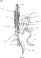
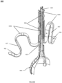
- Figs. 22A-B and Figs. 23A-B illustrate a tricuspid valve support device 400, in a deployed conformation, configured to be anchored at the annulus of the tricuspid valve in correspondence of commissures of the native leaflets of the tricuspid valve.
- the device 400 comprises an anchoring mechanism 410, which can contain one or more (e.g., one, two, three, four, or more) support arms 415, and its connected via a threaded shaft 419 to the tricuspid valve flow optimizer 440.
- the arms 415 can be radially disposed from the central axis of the device 400 and can be single ribbons or rods defining geometric, regular and/or random shapes, as illustrated.
- the arms 415 can be formed by a wire defining a closed shape.
- the end region (or distal end region) 416 of the arms 415a-415c is contoured to mate with the tissue wall of the tricuspid valve annulus at the commissures of the native leaflets.
- the intermediate portion 417 of the arm 415 is shaped to conform to the inner supra-annular wall of the right atrium to provide further support and/or stabilization.
- Fig. 25 illustrates the tricuspid valve support device 400 in a crimped conformation as it can be loaded into an intravascular delivery catheter.
- Tricuspid valve flow optimizer 440 can have similar or the same construction as the tricuspid valve flow optimizer 140, as described above in the context of device 100.
- the tricuspid valve flow optimizer 440 can be connected to the threaded shaft 419.
- the tricuspid valve flow optimizer 440 can be supported in the proximal direction by commissures/atrial wall anchoring mechanism 410 via the threaded shaft 419.
- Figs. 22A-23B shows the shaft 419 as being threaded
- the shaft 419 can be threaded and/or non-threaded, without limitation.
- the anchoring mechanism 410 can be connected to the shaft 419 via any mechanism that is same as and/or different from threading.
- the Device 400 further comprises commissures anchoring mechanism 410 which extends proximally from tricuspid valve flow optimizer 440 into the right atrium (not shown).
- the commissures anchoring mechanism 410 can comprise one or more (e.g., one, two, three, four, or more) anchoring arms 415.
- the anchoring arms 415 can have identical or individual shapes and/or length (shown in Fig. 24B ). As shown in Figs.
- the end regions (or the distal end regions) 416 of the arms 415a-415c mate with the tissue wall of the tricuspid valve annulus at the commissures of the leaflets, and the intermediate portion 417 rests against the inner supra-annular wall of the right atrium to provide further retention and stabilization to the tricuspid valve flow optimizer 440.
- the arms 415a-415c are formed from a memory shape material (e.g., NiTi) such that they are self-expanding when released from the delivery catheter.
- Figs. 29A-29B show an exemplary range of expansion of the shape of the arm 415a from the center axis of the device.
- the arm 415a can expand into either of the shapes shown in Figs. 29A-29B and/or any intermediate shapes between the shapes shown in Figs. 29A-29B , allowing placement and/or fitting of commissures anchoring mechanism 410 in tricuspid valve annuli of variable shape and size. Similar range of displacement applies to the arms 415a-415c.
- the arms 415a-415c can comprise, on the tissue-facing surface, a friction enhancing layer (e.g., polymer) including, for example, Velcro ® and micro-barbs, in order to enhance adhesion with the tissue at the commissures and at the inner supra-annular wall.
- the inner core 418, threaded shaft 419, locking collar 420 as shown in Fig. 24B can be machined from standard metallic alloys or polymers.
- the arm 415a protrudes proximally in a cylindrical shape.
- the arm 415a includes a proximal end region that includes a cylindrical protrusion.
- the inner core 418 can sit within the cylindrical shape protruding from the arm 415a.
- snap-fit edge 421 on the inner core 418 is devised to mate with notch 422 of the arm 415a, axially interlocking the components while still allowing limited rotation of inner core 418 within the arm 415a.
- the arm 415b is mated to the inner core 418 within matching groove 464 defined on the inner core 418, allowing combined rotation of the arm 415b with inner core 418.
- the arm 415c protrudes proximally in a cylindrically-shaped central portion.
- the central portion of the arm 415c can be inserted on the inner core 418 by mating in a groove 423 defined on the inner core 418, allowing the arm 415a to be rotated independently from inner core 418.
- Clockwise (CW) and/or counterclockwise (CCW) rotations of arm 415b can be limited by the edges of groove 423 on the inner core 418 within which the central portion of the arm 415c is mated.
- the arm 415c can be radially displaced by rotating CW or CCW a proximal end region of the arm 415c.
- the proximal end region of the arm 415c protrudes through the locking collar 420.
- the arm 415b can be radially displaced by rotating clockwise or counterclockwise the proximal end region of the inner core 418 protruding along the threaded shaft 419.
- an operator can individually position arms 415a-415c at different relative angles, matching angles across the commissures of the leaflets of the patients' native tricuspid valves.
- the rotating arms 415a-415c can be performed pre-procedurally (for example, prior to loading of the device 400 into the delivery catheter), and/or intra-procedurally (for example, prior to loading of the device 400 into the delivery catheter) via the device's delivery system controls.
- the threaded shaft 419 supports the flow optimizer 440 and is threaded through the inner core 418 as shown in Fig. 23A and Fig. 23B .
- CW and/or CCW rotations of the distal end region of the threaded shaft 419 can axially displace the distallyconnected flow optimizer 440 in the distal and proximal longitudinal directions, allowing shortening or extending the relative distance between the flow optimizer 440 and commissures anchoring mechanism 410, and/or to change the radial orientation of the flow optimizer 440 relatively to the anchoring arms 415a-415c.
- the locking collar 420 is shown as sitting on the proximal end of the anchoring mechanism 410, over the inner core 418 and the arm 415c as shown in Fig. 34A and Fig. 34B . As shown in Figs. 34C and 34D , the proximal surface 424 of the locking collar 420 can be displaced distally until being mated with a proximal cylindrical surface 425 of the arm 415a. The proximal surface 424 of the locking collar 420 can engage a snap-fit edge 426 of the inner core 418.
- the locking collar 420 compresses the arm 415a over the inner core 418, while radially constraining the arm 415c and the proximal ends of the inner core 418 over the threaded shaft 419, thus locking simultaneously the relative radial and axial positions of the inner core 418, the arms 415a-b-c and the threaded shaft 419.
- the commissures anchoring mechanism 410 can be coupled with a height adjustment mechanism to allow discrete individual control of the expansion or contraction of each arm 415.
- the end regions (or distal end regions) and/or the intermediate portions of the anchoring arms 415a-415c can be connected to cables 431.
- the proximal ends of the cable 431 are connected to sliders 432.
- the longitudinal cross-sectional profile of the sliders 432 is configured to mate with that of notches 433 cut along the cylindrical protrusion of the arm 415a.
- Expansion or contraction of the arms 415a-415c relative to the center axis of the anchoring mechanism can be individually controlled by longitudinally displacing distally or proximally the slider 432 along the arm 415a such that detents 434 disengage and re-engage with the sliders 432 as shown in Figs. 39A-39B .
- the detents 434 are configured to allow sliding in both distal and proximal directions.
- unidirectional detents 434 are configured to allow translocation in either the distal direction (e.g. towards the ventricle) or the proximal direction (e.g. towards the atrium).
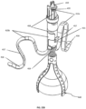
- device 400 can be loaded within an intravascular catheter 450 as shown in Fig. 40A and 40B , and delivered to the right atrium and into the tricuspid valve either via transfemoral access through the IVC, or via right internal jugular vein access of the IVC.
- the distal end of outer lumen 451 can be partially retracted to allow the expansion of the flow optimizer 440 and partial opening of the anchoring arms 415 (shown in Fig. 41A ).
- the radial position of the arm 415c can be modified by rotating CW or CCW the delivery system mid lumen 452 (shown in Fig. 42B ).
- the mid lumen 452 is connected via the slider 453 (shown in Fig. 42A ) to the proximal end of the Arm 415c.
- a slider 455 on an inner lumen 454 can be advanced to engage mating notch 456 at the distal end region of the inner core 418.
- the radial position of the arm 415b can be modified rotating CW or CCW the delivery system inner lumen 454.
- the slider 455 on the inner lumen 454 can be retracted by the operator, thus disengaging the rotation control of Arm 415b, and then the height and orientation of the flow optimizer 440 can be modified by rotating CW or CCW the inner lumen 454.
- locking the positions of the anchoring arms and of flow optimizer 440 can be achieved by sliding distally the slider 453 and advancing the locking collar 420 until is mated with the arm 415a.
- the outer lumen 451 can be further retrieved to allow the anchoring arms 415 to fully reach the annulus of the tricuspid valve at the commissures of the leaflets and/or at the supra-annular wall of the right atrium.
- the catheter operator can rotate (for example, CCW) the inner lumen 454 to disengage the threaded shaft 419, allowing release of the device and retrieval of the delivery system catheter.
- an additional outer lumen (not shown) with three separate sliders (not shown) can be added to the delivery system to allow the operator to modify the position of the sliders 432 (shown in Figs. 39A-39B ), and thus controlling the expansion and/or contraction of each individual anchoring arm 415.
Landscapes
- Health & Medical Sciences (AREA)
- Cardiology (AREA)
- Engineering & Computer Science (AREA)
- Biomedical Technology (AREA)
- Heart & Thoracic Surgery (AREA)
- Transplantation (AREA)
- Oral & Maxillofacial Surgery (AREA)
- Vascular Medicine (AREA)
- Life Sciences & Earth Sciences (AREA)
- Animal Behavior & Ethology (AREA)
- General Health & Medical Sciences (AREA)
- Public Health (AREA)
- Veterinary Medicine (AREA)
- Manufacturing & Machinery (AREA)
- Prostheses (AREA)
Applications Claiming Priority (3)
| Application Number | Priority Date | Filing Date | Title |
|---|---|---|---|
| US201662437523P | 2016-12-21 | 2016-12-21 | |
| EP17829864.2A EP3558164B1 (de) | 2016-12-21 | 2017-12-21 | Herzklappenhaltevorrichtung und verfahren zur herstellung davon |
| PCT/US2017/067817 WO2018119192A1 (en) | 2016-12-21 | 2017-12-21 | Heart valve support device and methods for making and using the same |
Related Parent Applications (2)
| Application Number | Title | Priority Date | Filing Date |
|---|---|---|---|
| EP17829864.2A Division EP3558164B1 (de) | 2016-12-21 | 2017-12-21 | Herzklappenhaltevorrichtung und verfahren zur herstellung davon |
| EP17829864.2A Division-Into EP3558164B1 (de) | 2016-12-21 | 2017-12-21 | Herzklappenhaltevorrichtung und verfahren zur herstellung davon |
Publications (2)
| Publication Number | Publication Date |
|---|---|
| EP4480453A2 true EP4480453A2 (de) | 2024-12-25 |
| EP4480453A3 EP4480453A3 (de) | 2025-01-08 |
Family
ID=60991614
Family Applications (2)
| Application Number | Title | Priority Date | Filing Date |
|---|---|---|---|
| EP24197322.1A Pending EP4480453A3 (de) | 2016-12-21 | 2017-12-21 | Herzklappenstützvorrichtung und verfahren zur herstellung und verwendung davon |
| EP17829864.2A Active EP3558164B1 (de) | 2016-12-21 | 2017-12-21 | Herzklappenhaltevorrichtung und verfahren zur herstellung davon |
Family Applications After (1)
| Application Number | Title | Priority Date | Filing Date |
|---|---|---|---|
| EP17829864.2A Active EP3558164B1 (de) | 2016-12-21 | 2017-12-21 | Herzklappenhaltevorrichtung und verfahren zur herstellung davon |
Country Status (4)
| Country | Link |
|---|---|
| US (3) | US10765518B2 (de) |
| EP (2) | EP4480453A3 (de) |
| CN (2) | CN110290764B (de) |
| WO (1) | WO2018119192A1 (de) |
Families Citing this family (133)
| Publication number | Priority date | Publication date | Assignee | Title |
|---|---|---|---|---|
| WO2006097931A2 (en) | 2005-03-17 | 2006-09-21 | Valtech Cardio, Ltd. | Mitral valve treatment techniques |
| US9883943B2 (en) | 2006-12-05 | 2018-02-06 | Valtech Cardio, Ltd. | Implantation of repair devices in the heart |
| US11259924B2 (en) | 2006-12-05 | 2022-03-01 | Valtech Cardio Ltd. | Implantation of repair devices in the heart |
| US11660190B2 (en) | 2007-03-13 | 2023-05-30 | Edwards Lifesciences Corporation | Tissue anchors, systems and methods, and devices |
| US8382829B1 (en) | 2008-03-10 | 2013-02-26 | Mitralign, Inc. | Method to reduce mitral regurgitation by cinching the commissure of the mitral valve |
| US8652202B2 (en) | 2008-08-22 | 2014-02-18 | Edwards Lifesciences Corporation | Prosthetic heart valve and delivery apparatus |
| US8545553B2 (en) | 2009-05-04 | 2013-10-01 | Valtech Cardio, Ltd. | Over-wire rotation tool |
| EP3848002A1 (de) | 2008-12-22 | 2021-07-14 | Valtech Cardio, Ltd. | Einstellbare annuloplastievorrichtungen und einstellmechanismen dafür |
| US8715342B2 (en) | 2009-05-07 | 2014-05-06 | Valtech Cardio, Ltd. | Annuloplasty ring with intra-ring anchoring |
| US8241351B2 (en) | 2008-12-22 | 2012-08-14 | Valtech Cardio, Ltd. | Adjustable partial annuloplasty ring and mechanism therefor |
| US10517719B2 (en) | 2008-12-22 | 2019-12-31 | Valtech Cardio, Ltd. | Implantation of repair devices in the heart |
| US8353956B2 (en) | 2009-02-17 | 2013-01-15 | Valtech Cardio, Ltd. | Actively-engageable movement-restriction mechanism for use with an annuloplasty structure |
| US9968452B2 (en) | 2009-05-04 | 2018-05-15 | Valtech Cardio, Ltd. | Annuloplasty ring delivery cathethers |
| US12485010B2 (en) | 2009-05-07 | 2025-12-02 | Edwards Lifesciences Innovation (Israel) Ltd. | Multiple anchor delivery tool |
| US9180007B2 (en) | 2009-10-29 | 2015-11-10 | Valtech Cardio, Ltd. | Apparatus and method for guide-wire based advancement of an adjustable implant |
| US10098737B2 (en) | 2009-10-29 | 2018-10-16 | Valtech Cardio, Ltd. | Tissue anchor for annuloplasty device |
| US8734467B2 (en) | 2009-12-02 | 2014-05-27 | Valtech Cardio, Ltd. | Delivery tool for implantation of spool assembly coupled to a helical anchor |
| US8449599B2 (en) | 2009-12-04 | 2013-05-28 | Edwards Lifesciences Corporation | Prosthetic valve for replacing mitral valve |
| EP2723274B1 (de) | 2011-06-23 | 2017-12-27 | Valtech Cardio, Ltd. | Verschlusselement zur verwendung mit einer annuloplastiestruktur |
| US10792152B2 (en) | 2011-06-23 | 2020-10-06 | Valtech Cardio, Ltd. | Closed band for percutaneous annuloplasty |
| US8858623B2 (en) | 2011-11-04 | 2014-10-14 | Valtech Cardio, Ltd. | Implant having multiple rotational assemblies |
| EP3970627B1 (de) | 2011-11-08 | 2023-12-20 | Edwards Lifesciences Innovation (Israel) Ltd. | Gesteuerte lenkfunktionalität für ein implantatabgabewerkzeug |
| CN104203157B (zh) | 2011-12-12 | 2016-02-03 | 戴维·阿隆 | 心脏瓣膜修补器械 |
| CA2885354A1 (en) | 2012-09-29 | 2014-04-03 | Mitralign, Inc. | Plication lock delivery system and method of use thereof |
| WO2014064694A2 (en) | 2012-10-23 | 2014-05-01 | Valtech Cardio, Ltd. | Controlled steering functionality for implant-delivery tool |
| US10376266B2 (en) | 2012-10-23 | 2019-08-13 | Valtech Cardio, Ltd. | Percutaneous tissue anchor techniques |
| WO2014087402A1 (en) | 2012-12-06 | 2014-06-12 | Valtech Cardio, Ltd. | Techniques for guide-wire based advancement of a tool |
| US9439763B2 (en) | 2013-02-04 | 2016-09-13 | Edwards Lifesciences Corporation | Prosthetic valve for replacing mitral valve |
| EP2961351B1 (de) | 2013-02-26 | 2018-11-28 | Mitralign, Inc. | Vorrichtungen zur perkutanen reparatur der trikuspidalklappe |
| US10449333B2 (en) | 2013-03-14 | 2019-10-22 | Valtech Cardio, Ltd. | Guidewire feeder |
| WO2014152503A1 (en) | 2013-03-15 | 2014-09-25 | Mitralign, Inc. | Translation catheters, systems, and methods of use thereof |
| US9763781B2 (en) * | 2013-05-07 | 2017-09-19 | George Kramer | Inflatable transcatheter intracardiac devices and methods for treating incompetent atrioventricular valves |
| US10070857B2 (en) | 2013-08-31 | 2018-09-11 | Mitralign, Inc. | Devices and methods for locating and implanting tissue anchors at mitral valve commissure |
| US10299793B2 (en) | 2013-10-23 | 2019-05-28 | Valtech Cardio, Ltd. | Anchor magazine |
| US9622863B2 (en) | 2013-11-22 | 2017-04-18 | Edwards Lifesciences Corporation | Aortic insufficiency repair device and method |
| US9610162B2 (en) | 2013-12-26 | 2017-04-04 | Valtech Cardio, Ltd. | Implantation of flexible implant |
| EP3200726B1 (de) | 2014-09-29 | 2023-07-05 | The Provost, Fellows, Foundation Scholars, & the other members of Board, of the College of the Holy & Undiv. Trinity of Queen Elizabeth near Dublin | Vorrichtung zur herzklappenbehandlung |
| EP3206629B1 (de) | 2014-10-14 | 2021-07-14 | Valtech Cardio, Ltd. | Vorrichtung zur rückhaltung von herzklappensegel |
| CN111437068B (zh) | 2014-12-04 | 2023-01-17 | 爱德华兹生命科学公司 | 用于修复心脏瓣膜的经皮夹具 |
| US20160256269A1 (en) | 2015-03-05 | 2016-09-08 | Mitralign, Inc. | Devices for treating paravalvular leakage and methods use thereof |
| EP3288496B1 (de) | 2015-04-30 | 2024-05-29 | Edwards Lifesciences Innovation (Israel) Ltd. | Technologien für die annuloplastie |
| ES3001450T3 (en) | 2015-05-14 | 2025-03-05 | Edwards Lifesciences Corp | Heart valve sealing devices and delivery devices therefor |
| WO2017117370A2 (en) | 2015-12-30 | 2017-07-06 | Mitralign, Inc. | System and method for reducing tricuspid regurgitation |
| US11219746B2 (en) | 2016-03-21 | 2022-01-11 | Edwards Lifesciences Corporation | Multi-direction steerable handles for steering catheters |
| US10835714B2 (en) | 2016-03-21 | 2020-11-17 | Edwards Lifesciences Corporation | Multi-direction steerable handles for steering catheters |
| US10799675B2 (en) | 2016-03-21 | 2020-10-13 | Edwards Lifesciences Corporation | Cam controlled multi-direction steerable handles |
| US10702274B2 (en) | 2016-05-26 | 2020-07-07 | Edwards Lifesciences Corporation | Method and system for closing left atrial appendage |
| US10973638B2 (en) | 2016-07-07 | 2021-04-13 | Edwards Lifesciences Corporation | Device and method for treating vascular insufficiency |
| GB201611910D0 (en) | 2016-07-08 | 2016-08-24 | Valtech Cardio Ltd | Adjustable annuloplasty device with alternating peaks and troughs |
| CA3041455A1 (en) * | 2016-10-19 | 2018-05-03 | Piotr Chodor | Stent of aortic valve implanted transcatheterly |
| US12485005B2 (en) * | 2016-10-19 | 2025-12-02 | Piotr Chodór | Stent of aortic valve |
| US10653862B2 (en) | 2016-11-07 | 2020-05-19 | Edwards Lifesciences Corporation | Apparatus for the introduction and manipulation of multiple telescoping catheters |
| EP4480453A3 (de) | 2016-12-21 | 2025-01-08 | TriFlo Cardiovascular Inc. | Herzklappenstützvorrichtung und verfahren zur herstellung und verwendung davon |
| US10905554B2 (en) | 2017-01-05 | 2021-02-02 | Edwards Lifesciences Corporation | Heart valve coaptation device |
| PL3558169T3 (pl) | 2017-04-18 | 2022-04-04 | Edwards Lifesciences Corporation | Urządzenia do uszczelniania zastawki serca i urządzenia do ich doprowadzania |
| US11224511B2 (en) | 2017-04-18 | 2022-01-18 | Edwards Lifesciences Corporation | Heart valve sealing devices and delivery devices therefor |
| US11045627B2 (en) | 2017-04-18 | 2021-06-29 | Edwards Lifesciences Corporation | Catheter system with linear actuation control mechanism |
| US10799312B2 (en) | 2017-04-28 | 2020-10-13 | Edwards Lifesciences Corporation | Medical device stabilizing apparatus and method of use |
| US10959846B2 (en) | 2017-05-10 | 2021-03-30 | Edwards Lifesciences Corporation | Mitral valve spacer device |
| US11051940B2 (en) | 2017-09-07 | 2021-07-06 | Edwards Lifesciences Corporation | Prosthetic spacer device for heart valve |
| US11065117B2 (en) | 2017-09-08 | 2021-07-20 | Edwards Lifesciences Corporation | Axisymmetric adjustable device for treating mitral regurgitation |
| US11110251B2 (en) | 2017-09-19 | 2021-09-07 | Edwards Lifesciences Corporation | Multi-direction steerable handles for steering catheters |
| WO2019079252A1 (en) * | 2017-10-20 | 2019-04-25 | Edwards Lifesciences Corporation | LOCALIZED FUSION OF NATIVE VALVES USING AN ACTIVE ADHESIVE |
| US10835221B2 (en) | 2017-11-02 | 2020-11-17 | Valtech Cardio, Ltd. | Implant-cinching devices and systems |
| US11135062B2 (en) | 2017-11-20 | 2021-10-05 | Valtech Cardio Ltd. | Cinching of dilated heart muscle |
| US10076415B1 (en) | 2018-01-09 | 2018-09-18 | Edwards Lifesciences Corporation | Native valve repair devices and procedures |
| US10245144B1 (en) | 2018-01-09 | 2019-04-02 | Edwards Lifesciences Corporation | Native valve repair devices and procedures |
| US10105222B1 (en) | 2018-01-09 | 2018-10-23 | Edwards Lifesciences Corporation | Native valve repair devices and procedures |
| US10973639B2 (en) | 2018-01-09 | 2021-04-13 | Edwards Lifesciences Corporation | Native valve repair devices and procedures |
| US10123873B1 (en) | 2018-01-09 | 2018-11-13 | Edwards Lifesciences Corporation | Native valve repair devices and procedures |
| US10136993B1 (en) | 2018-01-09 | 2018-11-27 | Edwards Lifesciences Corporation | Native valve repair devices and procedures |
| US10231837B1 (en) | 2018-01-09 | 2019-03-19 | Edwards Lifesciences Corporation | Native valve repair devices and procedures |
| US10159570B1 (en) | 2018-01-09 | 2018-12-25 | Edwards Lifesciences Corporation | Native valve repair devices and procedures |
| US10111751B1 (en) | 2018-01-09 | 2018-10-30 | Edwards Lifesciences Corporation | Native valve repair devices and procedures |
| US10238493B1 (en) | 2018-01-09 | 2019-03-26 | Edwards Lifesciences Corporation | Native valve repair devices and procedures |
| JP7343393B2 (ja) | 2018-01-09 | 2023-09-12 | エドワーズ ライフサイエンシーズ コーポレイション | 天然心臓弁修復装置および処置 |
| CN111655200B (zh) | 2018-01-24 | 2023-07-14 | 爱德华兹生命科学创新(以色列)有限公司 | 瓣环成形术结构的收缩 |
| WO2019145941A1 (en) | 2018-01-26 | 2019-08-01 | Valtech Cardio, Ltd. | Techniques for facilitating heart valve tethering and chord replacement |
| EP3749253B1 (de) | 2018-02-09 | 2023-07-05 | The Provost, Fellows, Foundation Scholars, and the other members of Board, of the College of the Holy & Undiv. Trinity of Queen Elizabeth near Dublin | Herzklappentherapievorrichtung |
| WO2019195860A2 (en) | 2018-04-04 | 2019-10-10 | Vdyne, Llc | Devices and methods for anchoring transcatheter heart valve |
| US11389297B2 (en) | 2018-04-12 | 2022-07-19 | Edwards Lifesciences Corporation | Mitral valve spacer device |
| US11207181B2 (en) | 2018-04-18 | 2021-12-28 | Edwards Lifesciences Corporation | Heart valve sealing devices and delivery devices therefor |
| US20200390552A1 (en) * | 2018-07-10 | 2020-12-17 | Syntach Ag | Implantable cardiac valve improvement device, system and procedure |
| JP7387731B2 (ja) | 2018-07-12 | 2023-11-28 | エドワーズ ライフサイエンシーズ イノベーション (イスラエル) リミテッド | 弁輪形成システムおよびそのための係止ツール |
| US10595994B1 (en) | 2018-09-20 | 2020-03-24 | Vdyne, Llc | Side-delivered transcatheter heart valve replacement |
| US11344413B2 (en) | 2018-09-20 | 2022-05-31 | Vdyne, Inc. | Transcatheter deliverable prosthetic heart valves and methods of delivery |
| US10321995B1 (en) | 2018-09-20 | 2019-06-18 | Vdyne, Llc | Orthogonally delivered transcatheter heart valve replacement |
| US12186187B2 (en) | 2018-09-20 | 2025-01-07 | Vdyne, Inc. | Transcatheter deliverable prosthetic heart valves and methods of delivery |
| US11278437B2 (en) | 2018-12-08 | 2022-03-22 | Vdyne, Inc. | Compression capable annular frames for side delivery of transcatheter heart valve replacement |
| US11071627B2 (en) | 2018-10-18 | 2021-07-27 | Vdyne, Inc. | Orthogonally delivered transcatheter heart valve frame for valve in valve prosthesis |
| US10945844B2 (en) | 2018-10-10 | 2021-03-16 | Edwards Lifesciences Corporation | Heart valve sealing devices and delivery devices therefor |
| US11109969B2 (en) | 2018-10-22 | 2021-09-07 | Vdyne, Inc. | Guidewire delivery of transcatheter heart valve |
| EP3883500B1 (de) | 2018-11-20 | 2024-11-06 | Edwards Lifesciences Corporation | Freisetzungswerkzeuge zur freisetzung einer vorrichtung in einer nativen herzklappe |
| CN113301869A (zh) | 2018-11-21 | 2021-08-24 | 爱德华兹生命科学公司 | 心脏瓣膜密封装置、其递送装置以及取回装置 |
| CR20210312A (es) | 2018-11-29 | 2021-09-14 | Edwards Lifesciences Corp | Método y aparato de cateterización |
| US11253359B2 (en) | 2018-12-20 | 2022-02-22 | Vdyne, Inc. | Proximal tab for side-delivered transcatheter heart valves and methods of delivery |
| WO2020146842A1 (en) | 2019-01-10 | 2020-07-16 | Vdyne, Llc | Anchor hook for side-delivery transcatheter heart valve prosthesis |
| US11273032B2 (en) | 2019-01-26 | 2022-03-15 | Vdyne, Inc. | Collapsible inner flow control component for side-deliverable transcatheter heart valve prosthesis |
| US11185409B2 (en) | 2019-01-26 | 2021-11-30 | Vdyne, Inc. | Collapsible inner flow control component for side-delivered transcatheter heart valve prosthesis |
| CN113747858B (zh) | 2019-02-11 | 2024-11-01 | 爱德华兹生命科学公司 | 心脏瓣膜密封装置及其递送装置 |
| WO2020168081A1 (en) | 2019-02-14 | 2020-08-20 | Edwards Lifesciences Corporation | Heart valve sealing devices and delivery devices therefor |
| SG11202108606PA (en) | 2019-02-25 | 2021-09-29 | Edwards Lifesciences Corp | Heart valve sealing devices |
| EP4729034A2 (de) | 2019-03-05 | 2026-04-22 | VDyne, Inc. | Trikuspidalregurgitationssteuerungsvorrichtungen für orthogonale transkatheterherzklappenprothese |
| US11173027B2 (en) | 2019-03-14 | 2021-11-16 | Vdyne, Inc. | Side-deliverable transcatheter prosthetic valves and methods for delivering and anchoring the same |
| US11076956B2 (en) | 2019-03-14 | 2021-08-03 | Vdyne, Inc. | Proximal, distal, and anterior anchoring tabs for side-delivered transcatheter mitral valve prosthesis |
| CN114072106B (zh) | 2019-05-04 | 2025-09-19 | 维迪内股份有限公司 | 用于在自体瓣环中部署侧面递送的假体心脏瓣膜的束紧装置和方法 |
| EP3972534A4 (de) | 2019-05-22 | 2023-08-02 | Triflo Cardiovascular Inc. | Herzklappenhaltevorrichtung |
| AU2020284630A1 (en) | 2019-05-29 | 2021-11-18 | Edwards Lifesciences Innovation (Israel) Ltd. | Tissue anchor handling systems and methods |
| US12502167B2 (en) | 2019-07-16 | 2025-12-23 | Edwards Lifesciences Corporation | Tissue remodeling systems and methods |
| US12364606B2 (en) | 2019-07-23 | 2025-07-22 | Edwards Lifesciences Innovation (Israel) Ltd. | Fluoroscopic visualization of heart valve anatomy |
| WO2021014440A2 (en) | 2019-07-23 | 2021-01-28 | Valtech Cardio, Ltd. | Contraction of an annuloplasty structure |
| WO2021024183A1 (en) * | 2019-08-05 | 2021-02-11 | Croivalve Ltd. | Apparatus and methods for treating a defective cardiac valve |
| CN121101808A (zh) | 2019-08-20 | 2025-12-12 | 维迪内股份有限公司 | 用于可侧面递送经导管人工瓣膜的递送和取回装置和方法 |
| EP4021445B8 (de) | 2019-08-26 | 2025-12-10 | VDyne, Inc. | Seitlich einführbare transkatheterherzklappenprothesen |
| CN114258313A (zh) | 2019-08-28 | 2022-03-29 | 瓦尔泰克卡迪欧有限公司 | 低剖面可转向导管 |
| JP2022546160A (ja) | 2019-08-30 | 2022-11-04 | エドワーズ ライフサイエンシーズ イノベーション (イスラエル) リミテッド | アンカーチャネル先端 |
| KR20220066398A (ko) | 2019-09-25 | 2022-05-24 | 카디악 임플란츠 엘엘씨 | 심장 판막 고리 감소 시스템 |
| CA3143014A1 (en) | 2019-10-15 | 2021-04-22 | Edwards Lifesciences Corporation | Heart valve sealing devices and delivery devices therefor |
| WO2021084407A1 (en) | 2019-10-29 | 2021-05-06 | Valtech Cardio, Ltd. | Annuloplasty and tissue anchor technologies |
| US11234813B2 (en) | 2020-01-17 | 2022-02-01 | Vdyne, Inc. | Ventricular stability elements for side-deliverable prosthetic heart valves and methods of delivery |
| EP4096529B1 (de) | 2020-03-23 | 2025-05-07 | Edwards Lifesciences Innovation (Israel) Ltd. | Selbstsichernde winde |
| WO2021236634A2 (en) | 2020-05-20 | 2021-11-25 | Cardiac Implants, Llc | Reducing the diameter of a cardiac valve annulus with independent control over each of the anchors that are launched into the annulus |
| CA3182316A1 (en) | 2020-06-19 | 2021-12-23 | Edwards Lifesciences Innovation (Israel) Ltd. | Self-stopping tissue anchors |
| WO2022051241A1 (en) | 2020-09-01 | 2022-03-10 | Edwards Lifesciences Corporation | Medical device stabilizing systems |
| WO2022068188A1 (zh) * | 2020-09-29 | 2022-04-07 | 上海捍宇医疗科技股份有限公司 | 一种夹合器 |
| US11266502B1 (en) | 2020-12-14 | 2022-03-08 | Versa Vascular Inc. | System and method for cardiac valve repair |
| EP4284255A4 (de) | 2021-01-28 | 2024-12-18 | Triflo Cardiovascular Inc. | Freisetzungssystem für eine herzklappenhaltevorrichtung |
| EP4376769A1 (de) * | 2021-07-28 | 2024-06-05 | Croivalve Ltd. | Systeme zur freisetzung von prothesen zur behandlung einer herzklappe |
| CN114533347A (zh) * | 2022-02-18 | 2022-05-27 | 上海臻亿医疗科技有限公司 | 人工心脏瓣膜的锚固装置及人工心脏瓣膜系统 |
| JP2025534210A (ja) | 2022-10-14 | 2025-10-15 | ブイダイン,インコーポレイテッド | 弁輪上支持体を使用して人工心臓弁を送達するデバイス及び方法 |
| EP4658207A1 (de) * | 2023-01-31 | 2025-12-10 | Croivalve Ltd. | Systeme und verfahren zur freisetzung von prothesen zur behandlung einer herzklappe |
| USD1071198S1 (en) | 2023-06-28 | 2025-04-15 | Edwards Lifesciences Corporation | Cradle |
| WO2025235669A2 (en) * | 2024-05-10 | 2025-11-13 | Edwards Lifesciences Corporation | Atrioventricular regurgitation solutions |
Citations (2)
| Publication number | Priority date | Publication date | Assignee | Title |
|---|---|---|---|---|
| US20100298929A1 (en) * | 2005-02-07 | 2010-11-25 | Thornton Troy L | Methods, systems and devices for cardiac valve repair |
| WO2019010370A1 (en) * | 2017-07-06 | 2019-01-10 | Raghuveer Basude | FABRIC PREVENTION DEVICES AND ASSOCIATED METHODS |
Family Cites Families (122)
| Publication number | Priority date | Publication date | Assignee | Title |
|---|---|---|---|---|
| US307980A (en) | 1884-11-11 | Freight-elevator | ||
| DK124690D0 (da) | 1990-05-18 | 1990-05-18 | Henning Rud Andersen | Klapprotes til implantering i kroppen for erstatning af naturlig klap samt kateter til brug ved implantering af en saadan klapprotese |
| US6048189A (en) | 1995-04-05 | 2000-04-11 | Japan Synthetic Rubber Co., Ltd. | Blow molding apparatus |
| US5954766A (en) | 1997-09-16 | 1999-09-21 | Zadno-Azizi; Gholam-Reza | Body fluid flow control device |
| US10327743B2 (en) | 1999-04-09 | 2019-06-25 | Evalve, Inc. | Device and methods for endoscopic annuloplasty |
| US20050070999A1 (en) | 2000-02-02 | 2005-03-31 | Spence Paul A. | Heart valve repair apparatus and methods |
| US6797002B2 (en) | 2000-02-02 | 2004-09-28 | Paul A. Spence | Heart valve repair apparatus and methods |
| US6569198B1 (en) | 2000-03-31 | 2003-05-27 | Richard A. Wilson | Mitral or tricuspid valve annuloplasty prosthetic device |
| US6976995B2 (en) | 2002-01-30 | 2005-12-20 | Cardiac Dimensions, Inc. | Fixed length anchor and pull mitral valve device and method |
| US6764510B2 (en) | 2002-01-09 | 2004-07-20 | Myocor, Inc. | Devices and methods for heart valve treatment |
| KR20040071025A (ko) | 2003-02-06 | 2004-08-11 | 삼성전자주식회사 | 그릴 및 이를 갖춘 조리장치 |
| US7316706B2 (en) * | 2003-06-20 | 2008-01-08 | Medtronic Vascular, Inc. | Tensioning device, system, and method for treating mitral valve regurgitation |
| WO2005027797A1 (en) | 2003-09-23 | 2005-03-31 | Ersin Erek | A mitral web apparatus for mitral valve insufficiencies |
| ITTO20040135A1 (it) | 2004-03-03 | 2004-06-03 | Sorin Biomedica Cardio Spa | Protesi valvolare cardiaca |
| JP2008513060A (ja) | 2004-09-14 | 2008-05-01 | エドワーズ ライフサイエンシーズ アーゲー | 心臓弁逆流の処置のためのデバイスおよび方法 |
| WO2009053952A2 (en) | 2007-10-26 | 2009-04-30 | Mednua Limited | A medical device for use in treatment of a valve |
| EP1841383A1 (de) * | 2004-12-15 | 2007-10-10 | Mednua Limited | Medizinprodukt zur verwendung bei der behandlung einer klappe |
| US8470028B2 (en) | 2005-02-07 | 2013-06-25 | Evalve, Inc. | Methods, systems and devices for cardiac valve repair |
| SE531468C2 (sv) | 2005-04-21 | 2009-04-14 | Edwards Lifesciences Ag | En anordning för styrning av blodflöde |
| US7854762B2 (en) | 2005-05-20 | 2010-12-21 | Mayo Foundation For Medical Education And Research | Devices and methods for reducing cardiac valve regurgitation |
| US7776084B2 (en) | 2005-07-13 | 2010-08-17 | Edwards Lifesciences Corporation | Prosthetic mitral heart valve having a contoured sewing ring |
| WO2007025028A1 (en) | 2005-08-25 | 2007-03-01 | The Cleveland Clinic Foundation | Percutaneous atrioventricular valve and method of use |
| US20070061010A1 (en) | 2005-09-09 | 2007-03-15 | Hauser David L | Device and method for reshaping mitral valve annulus |
| US8092525B2 (en) | 2005-10-26 | 2012-01-10 | Cardiosolutions, Inc. | Heart valve implant |
| US8778017B2 (en) | 2005-10-26 | 2014-07-15 | Cardiosolutions, Inc. | Safety for mitral valve implant |
| US7785366B2 (en) | 2005-10-26 | 2010-08-31 | Maurer Christopher W | Mitral spacer |
| WO2007078772A1 (en) | 2005-12-15 | 2007-07-12 | The Cleveland Clinic Foundation | Apparatus and method for treating a regurgitant valve |
| US20070185571A1 (en) | 2006-02-06 | 2007-08-09 | The Cleveland Clinic Foundation | Apparatus and method for treating a regurgitant valve |
| US20070203391A1 (en) | 2006-02-24 | 2007-08-30 | Medtronic Vascular, Inc. | System for Treating Mitral Valve Regurgitation |
| US8932348B2 (en) | 2006-05-18 | 2015-01-13 | Edwards Lifesciences Corporation | Device and method for improving heart valve function |
| EP2032080B1 (de) | 2006-06-01 | 2017-05-03 | Edwards Lifesciences Corporation | Protheseneinsatz zur verbesserung der herzklappenfunktion |
| IE20070428A1 (en) | 2006-06-15 | 2007-12-21 | Mednua Ltd | A medical device suitable for use in treatment of a valve |
| US8449605B2 (en) | 2006-06-28 | 2013-05-28 | Kardium Inc. | Method for anchoring a mitral valve |
| US20080033541A1 (en) | 2006-08-02 | 2008-02-07 | Daniel Gelbart | Artificial mitral valve |
| US8876894B2 (en) | 2006-09-19 | 2014-11-04 | Medtronic Ventor Technologies Ltd. | Leaflet-sensitive valve fixation member |
| JO2704B1 (en) | 2007-09-21 | 2013-03-03 | جانسين فارماسوتيكا ان في | Interference inhibition factors between MD2 and B53 |
| US9848981B2 (en) | 2007-10-12 | 2017-12-26 | Mayo Foundation For Medical Education And Research | Expandable valve prosthesis with sealing mechanism |
| US8597347B2 (en) | 2007-11-15 | 2013-12-03 | Cardiosolutions, Inc. | Heart regurgitation method and apparatus |
| US20090222081A1 (en) | 2008-01-24 | 2009-09-03 | Coherex Medical, Inc. | Methods and apparatus for reducing valve prolapse |
| EP2349018B1 (de) * | 2008-10-27 | 2018-08-01 | Boston Scientific Scimed, Inc. | Chirurgisches nadel-und-anker-system mit zurückziehattributen |
| WO2010057262A1 (en) | 2008-11-21 | 2010-05-27 | Percutaneous Cardiovascular Solutions Pty Limited | Heart valve prosthesis and method |
| US8998982B2 (en) | 2009-01-12 | 2015-04-07 | Valve Medical Ltd. | Method and apparatus for fine adjustment of a percutaneous valve structure |
| CA2759242A1 (en) | 2009-03-17 | 2010-09-23 | Mitrassist Medical Ltd. | Heart valve prosthesis with collapsible valve and method of delivery thereof |
| US20110077733A1 (en) * | 2009-09-25 | 2011-03-31 | Edwards Lifesciences Corporation | Leaflet contacting apparatus and method |
| US8377115B2 (en) | 2009-11-16 | 2013-02-19 | Medtronic Vascular, Inc. | Implantable valve prosthesis for treating venous valve insufficiency |
| US8449599B2 (en) | 2009-12-04 | 2013-05-28 | Edwards Lifesciences Corporation | Prosthetic valve for replacing mitral valve |
| US8961596B2 (en) | 2010-01-22 | 2015-02-24 | 4Tech Inc. | Method and apparatus for tricuspid valve repair using tension |
| US9307980B2 (en) | 2010-01-22 | 2016-04-12 | 4Tech Inc. | Tricuspid valve repair using tension |
| US8475525B2 (en) | 2010-01-22 | 2013-07-02 | 4Tech Inc. | Tricuspid valve repair using tension |
| SE535140C2 (sv) | 2010-03-25 | 2012-04-24 | Jan Otto Solem | En implanterbar anordning, kit och system för förbättring av hjärtfunktionen, innefattande medel för generering av longitudinell rörelse av mitralisklaffen |
| US8408214B2 (en) | 2010-07-08 | 2013-04-02 | Benjamin Spenser | Method for implanting prosthetic valve |
| US8641757B2 (en) | 2010-09-10 | 2014-02-04 | Edwards Lifesciences Corporation | Systems for rapidly deploying surgical heart valves |
| EP2478868A1 (de) | 2011-01-25 | 2012-07-25 | The Provost, Fellows, Foundation Scholars, and the other Members of Board, of the College of the Holy and Undivided Trinity of Queen Elizabeth | Implantationsvorrichtung |
| US8845717B2 (en) | 2011-01-28 | 2014-09-30 | Middle Park Medical, Inc. | Coaptation enhancement implant, system, and method |
| WO2012175483A1 (en) | 2011-06-20 | 2012-12-27 | Jacques Seguin | Prosthetic leaflet assembly for repairing a defective cardiac valve and methods of using the same |
| EP3424468A1 (de) | 2011-07-21 | 2019-01-09 | 4Tech Inc. | Vorrichtung zur reparatur der trikuspidalklappe mithilfe von spannung |
| WO2013016618A2 (en) | 2011-07-27 | 2013-01-31 | The Cleveland Clinic Foundation | Apparatus, system, and method for treating a regurgitant heart valve |
| US10799360B2 (en) | 2011-07-27 | 2020-10-13 | The Cleveland Clinic Foundation | Systems and methods for treating a regurgitant heart valve |
| EA201400481A1 (ru) | 2011-10-19 | 2014-10-30 | Твелв, Инк. | Искусственные сердечно-клапанные устройства, искусственные митральные клапаны и соответствующие системы и способы |
| US9011515B2 (en) | 2012-04-19 | 2015-04-21 | Caisson Interventional, LLC | Heart valve assembly systems and methods |
| CA2871156C (en) | 2012-05-16 | 2020-06-30 | Edwards Lifesciences Corporation | Devices and methods for reducing cardiac valve regurgitation |
| CA2872611C (en) * | 2012-05-16 | 2020-09-15 | Edwards Lifesciences Corporation | Systems and methods for placing a coapting member between valvular leaflets |
| US9474605B2 (en) | 2012-05-16 | 2016-10-25 | Edwards Lifesciences Corporation | Devices and methods for reducing cardiac valve regurgitation |
| US10413402B2 (en) | 2012-06-22 | 2019-09-17 | Pierre Squara | Heart valve prostheses |
| US9510946B2 (en) | 2012-09-06 | 2016-12-06 | Edwards Lifesciences Corporation | Heart valve sealing devices |
| US20140163652A1 (en) | 2012-12-10 | 2014-06-12 | Thomas Witzel | Method for treating and repairing mitral valve annulus |
| US10856983B2 (en) * | 2013-01-25 | 2020-12-08 | Medtentia International Ltd. Oy | System for cardiac valve repair |
| US9439763B2 (en) | 2013-02-04 | 2016-09-13 | Edwards Lifesciences Corporation | Prosthetic valve for replacing mitral valve |
| AU2014214811B2 (en) * | 2013-02-08 | 2018-02-22 | Muffin Incorporated | Peripheral sealing venous check-valve |
| US10271949B2 (en) | 2013-03-12 | 2019-04-30 | St. Jude Medical, Cardiology Division, Inc. | Paravalvular leak occlusion device for self-expanding heart valves |
| CA2910753A1 (en) | 2013-03-13 | 2014-10-09 | Aortic Innovations, Llc | Dual frame stent and valve devices and implantation |
| US9232998B2 (en) | 2013-03-15 | 2016-01-12 | Cardiosolutions Inc. | Trans-apical implant systems, implants and methods |
| CN105246431B (zh) | 2013-05-20 | 2018-04-06 | 托尔福公司 | 可植入心脏瓣膜装置、二尖瓣修复装置以及相关系统和方法 |
| US20150100116A1 (en) | 2013-10-07 | 2015-04-09 | Medizinische Universitat Wien | Implant and method for improving coaptation of an atrioventricular valve |
| US10166098B2 (en) | 2013-10-25 | 2019-01-01 | Middle Peak Medical, Inc. | Systems and methods for transcatheter treatment of valve regurgitation |
| US9668861B2 (en) | 2014-03-15 | 2017-06-06 | Rex Medical, L.P. | Vascular device for treating venous valve insufficiency |
| CN104055605B (zh) | 2014-07-07 | 2016-06-01 | 宁波健世生物科技有限公司 | 一种用于阻止瓣膜反流的假体 |
| US9180005B1 (en) | 2014-07-17 | 2015-11-10 | Millipede, Inc. | Adjustable endolumenal mitral valve ring |
| WO2016040526A1 (en) | 2014-09-10 | 2016-03-17 | Cedars-Sinai Medical Center | Method and apparatus for percutaneous delivery and deployment of a cardiac valve prosthesis |
| GB2536538B (en) | 2014-09-17 | 2018-07-18 | Cardiomech As | Anchor for implantation in body tissue |
| ES2676060T3 (es) | 2014-09-26 | 2018-07-16 | Nvt Ag | Dispositivo implantable para el tratamiento de la regurgitación de la válvula mitral |
| EP3200726B1 (de) | 2014-09-29 | 2023-07-05 | The Provost, Fellows, Foundation Scholars, & the other members of Board, of the College of the Holy & Undiv. Trinity of Queen Elizabeth near Dublin | Vorrichtung zur herzklappenbehandlung |
| US9750605B2 (en) | 2014-10-23 | 2017-09-05 | Caisson Interventional, LLC | Systems and methods for heart valve therapy |
| CN107106296A (zh) | 2014-11-17 | 2017-08-29 | 二尖瓣辅助治疗有限公司 | 用于心脏瓣膜的辅助装置 |
| US10842626B2 (en) | 2014-12-09 | 2020-11-24 | Didier De Canniere | Intracardiac device to correct mitral regurgitation |
| US9517131B2 (en) | 2014-12-12 | 2016-12-13 | Than Nguyen | Cardiac valve repair device |
| CN110934665B (zh) | 2014-12-14 | 2022-04-12 | 特瑞森医疗有限公司 | 假体心脏瓣膜及控制通过孔口的流体的方法 |
| US10383726B2 (en) | 2015-01-13 | 2019-08-20 | George Kramer | Implantable transcatheter intracardiac devices and methods for treating incompetent atrioventricular valves |
| US9629720B2 (en) | 2015-05-04 | 2017-04-25 | Jacques Seguin | Apparatus and methods for treating cardiac valve regurgitation |
| DE102015005933A1 (de) | 2015-05-12 | 2016-11-17 | Coramaze Technologies Gmbh | Implantierbare Vorrichtung zur Verbesserung oder Behebung einer Herzklappeninsuffizienz |
| ES3001450T3 (en) | 2015-05-14 | 2025-03-05 | Edwards Lifesciences Corp | Heart valve sealing devices and delivery devices therefor |
| GB2539444A (en) | 2015-06-16 | 2016-12-21 | Ucl Business Plc | Prosthetic heart valve |
| WO2017035002A1 (en) | 2015-08-21 | 2017-03-02 | Twelve Inc. | Implantable heart valve devices, mitral valve repair devices and associated systems and methods |
| US20170056176A1 (en) | 2015-08-25 | 2017-03-02 | Edwards Lifesciences Corporation | Treatments for mitral valve insufficiency |
| US10117744B2 (en) | 2015-08-26 | 2018-11-06 | Edwards Lifesciences Cardiaq Llc | Replacement heart valves and methods of delivery |
| CN108472135B (zh) | 2015-12-10 | 2021-02-02 | 姆维亚克斯股份有限公司 | 用于使心脏瓣膜环再成形的装置、系统和方法 |
| PL3184081T3 (pl) | 2015-12-22 | 2021-10-04 | Medira Ag | Urządzenie protetyczne do wspomagania koaptacji zastawki mitralnej |
| WO2017117370A2 (en) | 2015-12-30 | 2017-07-06 | Mitralign, Inc. | System and method for reducing tricuspid regurgitation |
| US10321992B2 (en) | 2016-02-01 | 2019-06-18 | Medtronic, Inc. | Heart valve prostheses having multiple support arms and methods for percutaneous heart valve replacement |
| EP3426195A4 (de) | 2016-03-08 | 2019-11-20 | Dura LLC | Herzklappenflügelaustauschsystem und verfahren dafür |
| CN105852916B (zh) | 2016-04-14 | 2018-02-06 | 上海甲悦医疗器械有限公司 | 一种经心尖植入的二尖瓣柔性闭合板阻塞体及植入方法 |
| US10945842B2 (en) | 2016-08-04 | 2021-03-16 | Evalve, Inc. | Annular augmentation device for cardiac valve repair |
| WO2018042439A1 (en) | 2016-08-31 | 2018-03-08 | Corassist Cardiovascular Ltd. | Transcatheter mechanical aortic valve prosthesis |
| US10420565B2 (en) | 2016-11-29 | 2019-09-24 | Abbott Cardiovascular Systems Inc. | Cinch and post for tricuspid valve repair |
| US10779837B2 (en) | 2016-12-08 | 2020-09-22 | Evalve, Inc. | Adjustable arm device for grasping tissues |
| EP4480453A3 (de) | 2016-12-21 | 2025-01-08 | TriFlo Cardiovascular Inc. | Herzklappenstützvorrichtung und verfahren zur herstellung und verwendung davon |
| CA3051272C (en) | 2017-01-23 | 2023-08-22 | Cephea Valve Technologies, Inc. | Replacement mitral valves |
| AU2018203053B2 (en) | 2017-01-23 | 2020-03-05 | Cephea Valve Technologies, Inc. | Replacement mitral valves |
| EP3576670B1 (de) | 2017-02-06 | 2025-07-16 | Caisson Interventional LLC | Systeme für herzklappentherapie |
| WO2018145249A1 (zh) | 2017-02-07 | 2018-08-16 | 上海甲悦医疗器械有限公司 | 用于治疗三尖瓣反流的装置及其植入方法 |
| US10653524B2 (en) | 2017-03-13 | 2020-05-19 | Polares Medical Inc. | Device, system, and method for transcatheter treatment of valvular regurgitation |
| PL3558169T3 (pl) | 2017-04-18 | 2022-04-04 | Edwards Lifesciences Corporation | Urządzenia do uszczelniania zastawki serca i urządzenia do ich doprowadzania |
| EP3630014A4 (de) | 2017-05-26 | 2021-11-03 | The Johns Hopkins University | Systeme und verfahren zur behandlung von herzklappenfehlern |
| US11026785B2 (en) | 2017-06-05 | 2021-06-08 | Edwards Lifesciences Corporation | Mechanically expandable heart valve |
| US10779829B2 (en) | 2017-06-07 | 2020-09-22 | Evalve, Inc. | Tissue compression device for cardiac valve repair |
| CN110944599A (zh) | 2017-07-10 | 2020-03-31 | 克拉玛泽技术有限公司 | 心脏植入物 |
| KR101965637B1 (ko) | 2017-07-31 | 2019-04-03 | (주) 타우피엔유메디칼 | 폐동맥 삽입용 삼첨판막 역류증 시술용 기구 |
| US11173032B2 (en) | 2017-08-28 | 2021-11-16 | Edwards Lifesciences Corporation | Transcatheter device for treating mitral regurgitation |
| US10905549B2 (en) | 2017-09-19 | 2021-02-02 | Cardiovalve Ltd. | Prosthetic valve with overlapping atrial tissue anchors and ventricular tissue anchors |
| CN111132636B (zh) | 2017-09-27 | 2022-04-08 | W.L.戈尔及同仁股份有限公司 | 带有可扩张框架的假体瓣膜以及相关系统和方法 |
| US10806574B2 (en) | 2017-11-20 | 2020-10-20 | Medtronic Vascular, Inc. | Delivery systems having a temporary valve and methods of use |
| EP3972534A4 (de) | 2019-05-22 | 2023-08-02 | Triflo Cardiovascular Inc. | Herzklappenhaltevorrichtung |
-
2017
- 2017-12-21 EP EP24197322.1A patent/EP4480453A3/de active Pending
- 2017-12-21 US US15/850,255 patent/US10765518B2/en active Active
- 2017-12-21 WO PCT/US2017/067817 patent/WO2018119192A1/en not_active Ceased
- 2017-12-21 CN CN201780086306.5A patent/CN110290764B/zh active Active
- 2017-12-21 EP EP17829864.2A patent/EP3558164B1/de active Active
- 2017-12-21 CN CN202210431483.5A patent/CN115137529B/zh active Active
-
2019
- 2019-12-12 US US16/712,832 patent/US11833047B2/en active Active
-
2020
- 2020-10-14 US US17/070,850 patent/US20210022851A1/en active Pending
Patent Citations (2)
| Publication number | Priority date | Publication date | Assignee | Title |
|---|---|---|---|---|
| US20100298929A1 (en) * | 2005-02-07 | 2010-11-25 | Thornton Troy L | Methods, systems and devices for cardiac valve repair |
| WO2019010370A1 (en) * | 2017-07-06 | 2019-01-10 | Raghuveer Basude | FABRIC PREVENTION DEVICES AND ASSOCIATED METHODS |
Also Published As
| Publication number | Publication date |
|---|---|
| EP3558164A1 (de) | 2019-10-30 |
| EP4480453A3 (de) | 2025-01-08 |
| US20180168803A1 (en) | 2018-06-21 |
| US20200113679A1 (en) | 2020-04-16 |
| US11833047B2 (en) | 2023-12-05 |
| CN115137529B (zh) | 2025-12-02 |
| CN115137529A (zh) | 2022-10-04 |
| CN110290764B (zh) | 2022-04-29 |
| US20210022851A1 (en) | 2021-01-28 |
| EP3558164B1 (de) | 2024-10-09 |
| US10765518B2 (en) | 2020-09-08 |
| WO2018119192A1 (en) | 2018-06-28 |
| CN110290764A (zh) | 2019-09-27 |
Similar Documents
| Publication | Publication Date | Title |
|---|---|---|
| EP3558164B1 (de) | Herzklappenhaltevorrichtung und verfahren zur herstellung davon | |
| EP3612135B1 (de) | Abgabesysteme mit befestigungen für herzklappenvorrichtungen | |
| AU2013245201B2 (en) | Cardiac valve support structure | |
| US10105224B2 (en) | Cardiac valve support structure | |
| EP3151784B1 (de) | Prothesenklappe zum ersetzen einer mitralklappe | |
| AU2013227235B2 (en) | Single-ring cardiac valve support | |
| CN113873971A (zh) | 心脏瓣膜支撑设备 | |
| US20150094802A1 (en) | Single-ring cardiac valve support | |
| WO2012031141A2 (en) | Cardiac valve support structure | |
| JP7736575B2 (ja) | 人工心臓弁 | |
| US20250152347A1 (en) | Attachment of a marker to a commissure of a prosthetic heart valve | |
| HK40081219A (en) | Heart valve support device and methods for making and using the same | |
| HK40015815A (en) | Heart valve support device and methods for making the same | |
| HK40015815B (en) | Heart valve support device and methods for making the same | |
| HK40115606B (en) | Prosthetic valve for replacing a mitral valve | |
| WO2025175037A1 (en) | Prosthetic heart valve | |
| CN104507416B (zh) | 心脏瓣膜支撑结构 |
Legal Events
| Date | Code | Title | Description |
|---|---|---|---|
| PUAI | Public reference made under article 153(3) epc to a published international application that has entered the european phase |
Free format text: ORIGINAL CODE: 0009012 |
|
| STAA | Information on the status of an ep patent application or granted ep patent |
Free format text: STATUS: THE APPLICATION HAS BEEN PUBLISHED |
|
| PUAL | Search report despatched |
Free format text: ORIGINAL CODE: 0009013 |
|
| AC | Divisional application: reference to earlier application |
Ref document number: 3558164 Country of ref document: EP Kind code of ref document: P |
|
| AK | Designated contracting states |
Kind code of ref document: A2 Designated state(s): AL AT BE BG CH CY CZ DE DK EE ES FI FR GB GR HR HU IE IS IT LI LT LU LV MC MK MT NL NO PL PT RO RS SE SI SK SM TR |
|
| AK | Designated contracting states |
Kind code of ref document: A3 Designated state(s): AL AT BE BG CH CY CZ DE DK EE ES FI FR GB GR HR HU IE IS IT LI LT LU LV MC MK MT NL NO PL PT RO RS SE SI SK SM TR |
|
| RIC1 | Information provided on ipc code assigned before grant |
Ipc: A61F 2/24 20060101AFI20241205BHEP |
|
| STAA | Information on the status of an ep patent application or granted ep patent |
Free format text: STATUS: REQUEST FOR EXAMINATION WAS MADE |
|
| STAA | Information on the status of an ep patent application or granted ep patent |
Free format text: STATUS: EXAMINATION IS IN PROGRESS |
|
| 17P | Request for examination filed |
Effective date: 20250826 |
|
| 17Q | First examination report despatched |
Effective date: 20250912 |