EP4478476A2 - Klammeranordnungen, kabelbaumintegrationsanordnungen und batteriemodule - Google Patents
Klammeranordnungen, kabelbaumintegrationsanordnungen und batteriemodule Download PDFInfo
- Publication number
- EP4478476A2 EP4478476A2 EP24166914.2A EP24166914A EP4478476A2 EP 4478476 A2 EP4478476 A2 EP 4478476A2 EP 24166914 A EP24166914 A EP 24166914A EP 4478476 A2 EP4478476 A2 EP 4478476A2
- Authority
- EP
- European Patent Office
- Prior art keywords
- wiring harness
- bracket
- mounting
- connecting portion
- connector
- Prior art date
- Legal status (The legal status is an assumption and is not a legal conclusion. Google has not performed a legal analysis and makes no representation as to the accuracy of the status listed.)
- Pending
Links
Images


Classifications
-
- H—ELECTRICITY
- H01—ELECTRIC ELEMENTS
- H01M—PROCESSES OR MEANS, e.g. BATTERIES, FOR THE DIRECT CONVERSION OF CHEMICAL ENERGY INTO ELECTRICAL ENERGY
- H01M10/00—Secondary cells; Manufacture thereof
- H01M10/42—Methods or arrangements for servicing or maintenance of secondary cells or secondary half-cells
- H01M10/4207—Methods or arrangements for servicing or maintenance of secondary cells or secondary half-cells for several batteries or cells simultaneously or sequentially
-
- H—ELECTRICITY
- H01—ELECTRIC ELEMENTS
- H01M—PROCESSES OR MEANS, e.g. BATTERIES, FOR THE DIRECT CONVERSION OF CHEMICAL ENERGY INTO ELECTRICAL ENERGY
- H01M50/00—Constructional details or processes of manufacture of the non-active parts of electrochemical cells other than fuel cells, e.g. hybrid cells
- H01M50/20—Mountings; Secondary casings or frames; Racks, modules or packs; Suspension devices; Shock absorbers; Transport or carrying devices; Holders
- H01M50/298—Mountings; Secondary casings or frames; Racks, modules or packs; Suspension devices; Shock absorbers; Transport or carrying devices; Holders characterised by the wiring of battery packs
-
- H—ELECTRICITY
- H01—ELECTRIC ELEMENTS
- H01M—PROCESSES OR MEANS, e.g. BATTERIES, FOR THE DIRECT CONVERSION OF CHEMICAL ENERGY INTO ELECTRICAL ENERGY
- H01M10/00—Secondary cells; Manufacture thereof
- H01M10/42—Methods or arrangements for servicing or maintenance of secondary cells or secondary half-cells
- H01M10/48—Accumulators combined with arrangements for measuring, testing or indicating the condition of cells, e.g. the level or density of the electrolyte
- H01M10/482—Accumulators combined with arrangements for measuring, testing or indicating the condition of cells, e.g. the level or density of the electrolyte for several batteries or cells simultaneously or sequentially
-
- H—ELECTRICITY
- H01—ELECTRIC ELEMENTS
- H01M—PROCESSES OR MEANS, e.g. BATTERIES, FOR THE DIRECT CONVERSION OF CHEMICAL ENERGY INTO ELECTRICAL ENERGY
- H01M10/00—Secondary cells; Manufacture thereof
- H01M10/42—Methods or arrangements for servicing or maintenance of secondary cells or secondary half-cells
- H01M10/48—Accumulators combined with arrangements for measuring, testing or indicating the condition of cells, e.g. the level or density of the electrolyte
- H01M10/486—Accumulators combined with arrangements for measuring, testing or indicating the condition of cells, e.g. the level or density of the electrolyte for measuring temperature
-
- H—ELECTRICITY
- H01—ELECTRIC ELEMENTS
- H01M—PROCESSES OR MEANS, e.g. BATTERIES, FOR THE DIRECT CONVERSION OF CHEMICAL ENERGY INTO ELECTRICAL ENERGY
- H01M50/00—Constructional details or processes of manufacture of the non-active parts of electrochemical cells other than fuel cells, e.g. hybrid cells
- H01M50/20—Mountings; Secondary casings or frames; Racks, modules or packs; Suspension devices; Shock absorbers; Transport or carrying devices; Holders
- H01M50/204—Racks, modules or packs for multiple batteries or multiple cells
- H01M50/207—Racks, modules or packs for multiple batteries or multiple cells characterised by their shape
- H01M50/209—Racks, modules or packs for multiple batteries or multiple cells characterised by their shape adapted for prismatic or rectangular cells
-
- H—ELECTRICITY
- H01—ELECTRIC ELEMENTS
- H01M—PROCESSES OR MEANS, e.g. BATTERIES, FOR THE DIRECT CONVERSION OF CHEMICAL ENERGY INTO ELECTRICAL ENERGY
- H01M50/00—Constructional details or processes of manufacture of the non-active parts of electrochemical cells other than fuel cells, e.g. hybrid cells
- H01M50/50—Current conducting connections for cells or batteries
- H01M50/502—Interconnectors for connecting terminals of adjacent batteries; Interconnectors for connecting cells outside a battery casing
- H01M50/507—Interconnectors for connecting terminals of adjacent batteries; Interconnectors for connecting cells outside a battery casing comprising an arrangement of two or more busbars within a container structure, e.g. busbar modules
-
- H—ELECTRICITY
- H01—ELECTRIC ELEMENTS
- H01M—PROCESSES OR MEANS, e.g. BATTERIES, FOR THE DIRECT CONVERSION OF CHEMICAL ENERGY INTO ELECTRICAL ENERGY
- H01M50/00—Constructional details or processes of manufacture of the non-active parts of electrochemical cells other than fuel cells, e.g. hybrid cells
- H01M50/50—Current conducting connections for cells or batteries
- H01M50/569—Constructional details of current conducting connections for detecting conditions inside cells or batteries, e.g. details of voltage sensing terminals
-
- H—ELECTRICITY
- H01—ELECTRIC ELEMENTS
- H01R—ELECTRICALLY-CONDUCTIVE CONNECTIONS; STRUCTURAL ASSOCIATIONS OF A PLURALITY OF MUTUALLY-INSULATED ELECTRICAL CONNECTING ELEMENTS; COUPLING DEVICES; CURRENT COLLECTORS
- H01R11/00—Individual connecting elements providing two or more spaced connecting locations for conductive members which are, or may be, thereby interconnected, e.g. end pieces for wires or cables supported by the wire or cable and having means for facilitating electrical connection to some other wire, terminal, or conductive member, blocks of binding posts
- H01R11/11—End pieces or tapping pieces for wires, supported by the wire and for facilitating electrical connection to some other wire, terminal or conductive member
- H01R11/28—End pieces consisting of a ferrule or sleeve
- H01R11/281—End pieces consisting of a ferrule or sleeve for connections to batteries
- H01R11/288—Interconnections between batteries
-
- Y—GENERAL TAGGING OF NEW TECHNOLOGICAL DEVELOPMENTS; GENERAL TAGGING OF CROSS-SECTIONAL TECHNOLOGIES SPANNING OVER SEVERAL SECTIONS OF THE IPC; TECHNICAL SUBJECTS COVERED BY FORMER USPC CROSS-REFERENCE ART COLLECTIONS [XRACs] AND DIGESTS
- Y02—TECHNOLOGIES OR APPLICATIONS FOR MITIGATION OR ADAPTATION AGAINST CLIMATE CHANGE
- Y02E—REDUCTION OF GREENHOUSE GAS [GHG] EMISSIONS, RELATED TO ENERGY GENERATION, TRANSMISSION OR DISTRIBUTION
- Y02E60/00—Enabling technologies; Technologies with a potential or indirect contribution to GHG emissions mitigation
- Y02E60/10—Energy storage using batteries
Definitions
- the present disclosure relates to a technical field of batteries, and in particular to bracket assemblies, wiring harness integration assemblies, and battery modules.
- a battery module is a power module of a new energy power supply system, and generally consists of a cell, a connecting member, an acquisition wiring harness for signal sampling, a connector for signal output, a bracket assembly, and the like.
- the present disclosure provides bracket assemblies, wiring harness integration assemblies, and battery modules to solve the above technical problems.
- embodiments of the present disclosure provide a bracket assembly for a battery module, the bracket assembly including: a wiring harness bracket configured to mount an acquisition wiring harness, a side of the wiring harness bracket is provided with a mounting portion for mounting a connector, and a first connecting portion is protrudingly arranged on the mounting portion; and a fixing bracket detachably connected to the wiring harness bracket, the fixing bracket includes a fixing portion and a second connecting portion that are connected to each other, the fixing portion is configured to mount the connector, and the second connecting portion is detachably connected to the first connecting portion.
- embodiments of the present disclosure provide a wiring harness integration assembly including: the above bracket assembly; an acquisition wiring harness arranged on a wiring harness bracket of the bracket assembly; and a connector mounted on the fixing portion of the fixing bracket in the bracket assembly, the connector being electrically connected to the acquisition wiring harness.
- a fixing bracket detachably connected to the wiring harness bracket is provided, so that when the connector and the acquisition wiring harness are installed on the wiring harness bracket, the connector can be first fixed by the fixing part of the fixing bracket, and then the acquisition wiring harness is electrically connected to the connector, and then the fixing bracket, the connector and the acquisition wiring harness are integrally installed on the wiring harness bracket through the connection between the second connecting part and the first connecting part, thereby avoiding loosening of the acquisition wiring harness due to the excessive length thereof after the connector is fixed, thereby reducing the risk of signal collection failure.
- the wiring harness integration assembly provided in the present disclosure, by integrating the acquisition wiring harness, the connecting assembly, and the connector all on one bracket assembly, it is possible to realize high integration of the wiring harness integration assembly in the battery module so as to facilitate rapid assembly of the battery module.
- the battery module provided by the present disclosure includes a plurality of cells and a wiring harness integration assembly, the wiring harness integration assembly is electrically connected to the cells to collect signals such as voltage and temperature of the cells, and is electrically connected to the BMS module through a connector so as to output signals such as voltage and temperature monitored by the acquisition wiring harness, thereby realizing the monitoring and maintenance of the working state and service performance of the battery module to ensure safe and stable use of the battery module.
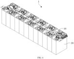
- battery module 10, wiring harness integration assembly; 100, bracket assembly; 110, wiring harness bracket; 111, mounting portion; 112, first connecting portion; 1121, chute; 1122, mounting port; 1123, stop block; 1124, stop portion; 120, fixing bracket; 121, fixing portion; 1211, first side surface; 1212, second side surface; 1213, mounting slot; 122, second connecting portion; 123, sliding block; 1231, avoidance slot; 124, abutment block; X, first direction; Y, second direction; 200, acquisition wiring harness; 300, connecting assembly; 400, connector; 410, elastic member; 20, cell.
- Embodiments of the present disclosure provide bracket assemblies, wiring harness integration assemblies, and battery modules, which are described in detail below. It should be noted that the order in which the following embodiments are described is not intended to limit the preferred order of the embodiments.
- an embodiment of the present disclosure provides a bracket assembly for a battery module, the battery module consists of a plurality of cells connected in series or in parallel.
- the bracket assembly When the plurality of cells are connected in series or in parallel, and signals such as a voltage or a temperature of the battery module are acquired and output, it is necessary to provide the bracket assembly above the cells, so as to facilitate the installation of a connecting assembly connecting the cells, a acquisition wiring harness, and a connector.
- the bracket assembly 100 includes a wiring harness bracket 110 and a fixing bracket 120 that is detachably connected to the wiring harness bracket 110.
- the wiring harness bracket 110 is configured to mount the acquisition wiring harness 200
- a side of the wiring harness bracket 110 is provided with a mounting portion 111
- the mounting portion 111 is configured to mount a connector 400
- a first connecting portion 112 is protrudingly arranged on the mounting portion 111 to facilitate detachable mounting of the fixing bracket 120.
- first connecting portion 112 and the second connecting portion 122 are not particularly limited, and it is only necessary to ensure that the fixing bracket 120 and the wiring harness bracket 110 are two separate individuals and can be detachably connected to each other.
- the bracket assembly 100 is used for a battery module 1, the bracket assembly 100 includes the wiring harness bracket 110 and the fixing bracket 120, the wiring harness bracket 110 is configured to mount the acquisition wiring harness 200, a side of the wiring harness bracket 110 is provided with the mounting portion 111, the mounting portion 111 configured to mount the connector 400, the first connecting portion 112 is protrudingly arranged on the mounting portion 111, the fixing bracket 120 is detachably connected to the wiring harness bracket 110, the fixing bracket 120 includes the fixing portion 121 and the second connecting portion 122 that are connected to each other, the fixing portion 121 is used for mounting the connector 400, and the second connecting portion 122 is detachably connected to the first connecting portion 112.
- the connector 400 can be first fixed by the fixing portion 121 of the fixing bracket 120, the acquisition wiring harness 200 is electrically connected to the connector 400, and then the fixing bracket 120, the connector 400 and the acquisition wiring harness 200 are integrally mounted to the wiring harness bracket 110 through the connection of the second connecting portion 122 and the first connecting portion 112, so that it is possible to avoid loosening of the acquisition wiring harness 200 due to the excessive length thereof after the connector 400 is fixed, thereby reducing the risk of signal acquisition failure.
- the sliding block 123 on the second connecting portion 122 slides into the chute 1121 from the mounting port 1122 of the first connecting portion 112, and slides along the extension direction of the chute 1121 to contact with each other.
- the first connecting portion 112 may be directly deformed by the plasticity of the first connecting portion 112, and after the sliding block 123 is slid into the chute 1121, the first connecting portion 112 and the second connecting portion 122 may be brought into contact with each other by a reaction force of plastic deformation.
- a stop block 1123 is protrudingly arranged on a bottom of the chute 1121, a side of the sliding block 123 facing the stop block 1123 is provided with an avoidance slot 1231, the avoidance slot 1231 extends through the sliding block 123 along a sliding direction of the sliding block 123, the avoidance slot 1231 is used for avoiding the stop block 1123, an abutment block 124 is protrudingly arranged on a bottom of the avoidance slot 1231, and the abutment block 124 is used for abutting a side of the stop block 1123 away from the mounting port 1122.
- the stopper block 1123 can restrict the upward movement of the fixing bracket 120, and prevent the fixing bracket 120 from moving upward and detaching from the wiring harness bracket 110.
- a surface of the sliding block 123 which is first in contact with the stop block 1123 during the sliding process can be provided as an inclined surface so as to reduce the resistance in the sliding process of the sliding block 123 into the chute 1121, thereby facilitating the installation of the fixing bracket 120 and the wiring harness bracket 110.
- the sliding block 123 and the second connecting portion 122 there is a gap between the sliding block 123 and the second connecting portion 122, and the two opposite side walls of the chute 1121 are provided with protruding stop portions 1124 for abutting against a side of the sliding block 123 facing the second connecting portion 122. That is, an end of the sliding block 123 away from the mounting portion 111 is connected to the second connecting portion 122, and an end of the sliding block 123 facing toward the mounting portion 111 is spaced apart from the second connecting portion 122, and a gap is formed between the second connecting portion 122 and the end of the sliding block 123 facing toward the mounting portion 111.
- the sliding block 123 slides into the gap between the stop portion 1124 and the bottom of the chute 1121 from the mounting port 1122, and a side of the sliding block 123 facing the second connecting portion 122 abuts against the stop portion 1124, that is, the stop portion 1124 is positioned between the second connecting portion 122 and the sliding block 123, so as to limit the movement of the fixing bracket 120 in the front, backward, left and right directions, thereby further improving the mounting stability of the fixing bracket 120 and the wiring harness bracket 110.
- the positions at which the chute 1121 on the first connecting portion 112 and the sliding block 123 on the second connecting portion 122 are provided can be interchanged, that is, the sliding block is provided on the first connecting portion 112, and the chute is provided on the second connecting portion 122, so that the fixing bracket 120 is detachably connected to the wiring harness bracket 110.
- the specific structure thereof can be described with reference to the related description in the foregoing embodiment, and details are not described herein.
- the mounting portion 111 is provided with two protruding first connecting portions 112 which are arranged in parallel in a first direction X
- the fixing bracket 120 includes two second connecting portions 122 which are connected to opposite ends of the fixing portion 121 in the first direction X respectively, and the second connecting portions 122 are connected in one-to-one correspondence with the first connecting portions 112. That is, the fixing bracket 120 is connected to the wiring harness bracket 110 at opposite ends of the fixing bracket 120 in the first direction X at the same time, so that the mounting stability of the fixing bracket 120 can be improved, and the stress on the fixing bracket 120 can be more uniform, thereby contributing to improving the structural stability of the fixing bracket 120.
- the fixing portion 121 has first and second side surfaces 1211 and 1212 opposite to each other in a second direction Y, the second connecting portion 122 is connected to the second side surface 1212, the first side surface 1211 is provided with a mounting slot 1213, the mounting slot 1213 extends in the second direction Y and extends through the second side surface 1212, and a side wall of the mounting slot 1213 is configured to abut the connector 400. That is, when the connector 400 is mounted, the connector 400 can be mounted to the mounting slot 1213 from the first side surface 1211 and protruded from the second side surface 1212, and the connector 400 can be fixed by abutting the side wall of the mounting slot 1213 against the connector 400. An end of the connector 400 protruding from the second side surface 1212 is configured to be electrically connected to the acquisition wiring harness 200.
- the second direction Y corresponds to the arrangement direction of the plurality of cells 20 in the battery module 1
- the first direction X is a direction perpendicular to the second direction Y in the horizontal plane, that is, the first direction X is the distribution direction of the positive and negative posts of a single cell 20.
- the first side surface 1211 is provided with at least two mounting slots 1213, which are spaced apart in the first direction X, each of the mounting slots 1213 can be used to mount the connector 400, so that at least two connectors 400 of the same type or different types can be mounted on the fixing bracket 120 at the same time to meet different design requirements of the battery module 1.
- an embodiment of the present disclosure further provides a wiring harness integration assembly, which includes a bracket assembly, and a specific structure of the bracket assembly is described with reference to the foregoing embodiments. Since the wiring harness integration assembly adopts all technical solutions of all the foregoing embodiments, it has at least all beneficial effects caused by the technical solutions of the foregoing embodiments, which are not repeated herein again.
- the wiring harness integration assembly 10 includes the bracket assembly 100, a connecting assembly 300, an acquisition wiring harness 200, and a connector 400
- the connecting assembly 300 is provided on the wiring harness bracket 110 of the bracket assembly 100
- the connecting assembly 300 is configured to be electrically connected to electrodes of the cells 20 in the battery module 1
- the acquisition wiring harness 200 is provided on the wiring harness bracket 110 of the bracket assembly 100
- the acquisition wiring harness 200 is electrically connected to the connecting assembly 300 to collect signals such as voltage and temperature of the cells 20
- the connector 400 is mounted on the fixing portion 121 of the fixing bracket 120 in the bracket assembly 100
- the connector 400 is electrically connected to the acquisition wiring harness 200 to realize output of the collected signals of the acquisition wiring harness 200.
- the acquisition wiring harness 200, the connecting assembly 300, and the connector 400 all on one bracket assembly 100, it is possible to achieve a high degree of integration of the wiring harness integration assembly 10 in the battery module 1 so as to facilitate rapid assembly of the battery module 1.
- the bracket assembly 100 includes the wiring harness bracket 110 and the fixing bracket 120, a side of the wiring harness bracket 110 is provided with a mounting portion 111, a first connecting portion 112 is protrudingly arranged on the mounting portion 111, the fixing bracket 120 includes a fixing portion 121 and a second connecting portion 122 that are connected to each other, the fixing portion 121 is used for mounting the connector 400, and the second connecting portion 122 is detachably connected to the first connecting portion 112.
- the connector 400 can be first fixed by the fixing portion 121 of the fixing bracket 120, the acquisition wiring harness 200 is electrically connected to the connector 400, and then the fixing bracket 120, the connector 400 and the acquisition wiring harness 200 are integrally mounted to the wiring harness bracket 110 through the connection of the second connecting portion 122 and the first connecting portion 112, so that it is possible to avoid loosening of the acquisition wiring harness 200 due to the excessive length thereof after the connector 400 is fixed, thereby reducing the risk of signal acquisition failure.
- the fixing portion 121 is provided with the mounting slot 1213, and at least one side of the connector 400 is provided with an elastic member 410 which abuts against the side wall of the mounting slot 1213 on the fixing portion 121, so that the connector 400 is mounted in the mounting slot 1213.
- an elastic member 410 which abuts against the side wall of the mounting slot 1213 on the fixing portion 121, so that the connector 400 is mounted in the mounting slot 1213.
- the fixing bracket 120 and the connector 400 can be tolerance-fitted, that is, the mounting slot 1213 on the fixing bracket 120 can be adapted to the connectors 400 of different sizes at the same time, so as to improve the applicability of the fixing bracket 120.
- the connector 400 is provided with an elastic member 410 on each of opposite sides in the first direction X, so that the connector 400 and the mounting slot 1213 of the fixing bracket 120 can be symmetrically fixed to reduce the stress concentration generated during the fixing process.
- the connecting assembly 300 includes a first connecting member and a second connecting member, the first connecting member is used for connecting two adjacent cells 20 in the battery module 1 to realize the series or parallel connection of the two adjacent cells 20, and the second connecting member is used for electrically connecting with an output electrode of the battery module 1.
- the output electrodes of the battery module 1 are located at both ends of the battery module 1 in the alignment direction of the plurality of cells 20, that is, the second connecting members are provided at both ends of the wiring harness bracket 110 so as to facilitate the connection design of the battery module 1 to the external output circuit.
- a thermistor NTC is provided at an end of the partial acquisition wiring harness 200 connected to the connecting assembly 300 to monitor the temperature of the corresponding cell 20 in the battery module 1.
- a layer of UV glue can be applied to the connection to enhance the welding strength of the acquisition wiring harness 200 and the connecting assembly 300, and the foreign matter can be prevented from contacting the welding area of the acquisition wiring harness 200 and the connecting assembly 300, thereby improving the connection stability of the acquisition wiring harness 200 and the connecting assembly 300.
- an embodiment of the present disclosure further provides a battery module including a wiring harness integration assembly, a specific structure of the wiring harness integration assembly refers to the above-described embodiment. Since the battery module employs all the technical solutions of all the above-described embodiments, it has at least all beneficial effects caused by the technical solutions of the foregoing embodiments, which are not repeated herein again.
- the battery module 1 includes the plurality of cells 20 and the wiring harness integration assembly 10 electrically connected to the cells 20 to collect signals such as voltage and temperature of the cells 20, and electrically connected to the BMS module through the connector 400 so as to output signals such as voltage and temperature monitored by the acquisition wiring harness 200, thereby enabling monitoring and maintenance of the operating state and service performance of the battery modules 1 to ensure safe and stable use of the battery modules 1.
- the wiring harness integration assembly 10 includes the bracket assembly 100 including the wiring harness bracket 110 and the fixing bracket 120, a side of the wiring harness bracket 110 is provided with the mounting portion 111, the first connecting portion 112 is protrudingly arranged on the mounting portion 111, the fixing bracket 120 includes the fixing portion 121 and the second connecting portion 122 which are connected to each other, the fixing portion 121 is used to mount the connector 400, and the second connecting portion 122 is detachably connected to the first connecting portion 112.
- the fixing bracket 120 which is detachably connected to the wiring harness bracket 110 is provided, so that when the connector 400 and the acquisition wiring harness 200 are mounted to the wiring harness bracket 110, the connector 400 can be first fixed by the fixing portion 121 of the fixing bracket 120, the acquisition wiring harness 200 is electrically connected to the connector 400, and then the fixing bracket 120, the connector 400 and the acquisition wiring harness 200 are integrally mounted to the wiring harness bracket 110 through the connection of the second connecting portion 122 and the first connecting portion 112, and the acquisition wiring harness 200 is fixed to the wiring harness bracket 110, thereby avoiding loosening of the acquisition wiring harness 200 due to the excessive length thereof after the connector 400 is fixed, thereby reducing the risk of signal acquisition failure.
Landscapes
- Chemical & Material Sciences (AREA)
- Chemical Kinetics & Catalysis (AREA)
- Electrochemistry (AREA)
- General Chemical & Material Sciences (AREA)
- Engineering & Computer Science (AREA)
- Manufacturing & Machinery (AREA)
- Battery Mounting, Suspending (AREA)
Applications Claiming Priority (1)
| Application Number | Priority Date | Filing Date | Title |
|---|---|---|---|
| CN202321556707.1U CN220138622U (zh) | 2023-06-16 | 2023-06-16 | 支架组件、线束集成组件及电池模组 |
Publications (2)
| Publication Number | Publication Date |
|---|---|
| EP4478476A2 true EP4478476A2 (de) | 2024-12-18 |
| EP4478476A3 EP4478476A3 (de) | 2024-12-25 |
Family
ID=88952525
Family Applications (1)
| Application Number | Title | Priority Date | Filing Date |
|---|---|---|---|
| EP24166914.2A Pending EP4478476A3 (de) | 2023-06-16 | 2024-03-27 | Klammeranordnungen, kabelbaumintegrationsanordnungen und batteriemodule |
Country Status (4)
| Country | Link |
|---|---|
| US (1) | US20240421414A1 (de) |
| EP (1) | EP4478476A3 (de) |
| CN (1) | CN220138622U (de) |
| WO (1) | WO2024255228A1 (de) |
Families Citing this family (1)
| Publication number | Priority date | Publication date | Assignee | Title |
|---|---|---|---|---|
| CN220138622U (zh) * | 2023-06-16 | 2023-12-05 | 惠州亿纬锂能股份有限公司 | 支架组件、线束集成组件及电池模组 |
Family Cites Families (7)
| Publication number | Priority date | Publication date | Assignee | Title |
|---|---|---|---|---|
| JP5304606B2 (ja) * | 2009-11-16 | 2013-10-02 | 住友電装株式会社 | ロック構造 |
| JP6182992B2 (ja) * | 2013-06-14 | 2017-08-23 | 株式会社Gsユアサ | 蓄電モジュール |
| JP6204876B2 (ja) * | 2014-06-04 | 2017-09-27 | 株式会社オートネットワーク技術研究所 | 温度センサの取付構造 |
| JP6788794B2 (ja) * | 2016-11-22 | 2020-11-25 | 株式会社オートネットワーク技術研究所 | 配線モジュール |
| CN212991245U (zh) * | 2020-09-23 | 2021-04-16 | 中航锂电技术研究院有限公司 | 线束板组件及电池模组 |
| CN212991246U (zh) * | 2020-09-23 | 2021-04-16 | 中航锂电技术研究院有限公司 | 线束板组件及电池模组 |
| CN220138622U (zh) * | 2023-06-16 | 2023-12-05 | 惠州亿纬锂能股份有限公司 | 支架组件、线束集成组件及电池模组 |
-
2023
- 2023-06-16 CN CN202321556707.1U patent/CN220138622U/zh active Active
-
2024
- 2024-01-09 WO PCT/CN2024/071341 patent/WO2024255228A1/zh not_active Ceased
- 2024-03-27 EP EP24166914.2A patent/EP4478476A3/de active Pending
- 2024-05-30 US US18/679,103 patent/US20240421414A1/en active Pending
Also Published As
| Publication number | Publication date |
|---|---|
| CN220138622U (zh) | 2023-12-05 |
| US20240421414A1 (en) | 2024-12-19 |
| EP4478476A3 (de) | 2024-12-25 |
| WO2024255228A1 (zh) | 2024-12-19 |
Similar Documents
| Publication | Publication Date | Title |
|---|---|---|
| KR100996957B1 (ko) | 전지모듈의 전극단자의 연결용 기계적 고정구 및전극단자의 연결방법 | |
| EP4478476A2 (de) | Klammeranordnungen, kabelbaumintegrationsanordnungen und batteriemodule | |
| CN117393949A (zh) | 一种ccs组件及电池包 | |
| CN218782309U (zh) | 信号采集装置及电池模组 | |
| WO2022213696A1 (zh) | 一种免焊式锂电池组 | |
| CN115372845A (zh) | 用于燃料电池电堆的电压巡检装置 | |
| CN112838278B (zh) | 一种电压信号采集模组结构 | |
| CN222735066U (zh) | 电池采集组件、电池模组和用电设备 | |
| CN219873946U (zh) | 一种电池包及新能源汽车 | |
| CN117060016A (zh) | 一种电池 | |
| CN213845422U (zh) | 锂离子电池模块 | |
| CN110098797B (zh) | 一种光伏组件电性能测试系统和测试方法 | |
| CN114597517A (zh) | 电池模组 | |
| CN221352879U (zh) | 采温单元和电池包 | |
| CN223797484U (zh) | 集成母排及电池包 | |
| CN112928377A (zh) | 集成盖板及动力电池模组 | |
| CN223757642U (zh) | 电池模组和电池包 | |
| CN223066421U (zh) | 一种电芯数据采集结构 | |
| CN221828091U (zh) | Ccs集成组件及电池包 | |
| CN221328005U (zh) | 一种ccs组件及电池包 | |
| CN219873950U (zh) | 一种电池模组导电排、电池模组和电池包 | |
| CN222914865U (zh) | 电池管理单元、集成母排和电池 | |
| CN223156243U (zh) | 一种锂电模组采样单元 | |
| EP4576397A1 (de) | Batteriemodul und batteriemodulsammelmechanismus | |
| CN213426605U (zh) | 一种用于电机测试的微机保护测控装置 |
Legal Events
| Date | Code | Title | Description |
|---|---|---|---|
| PUAI | Public reference made under article 153(3) epc to a published international application that has entered the european phase |
Free format text: ORIGINAL CODE: 0009012 |
|
| STAA | Information on the status of an ep patent application or granted ep patent |
Free format text: STATUS: REQUEST FOR EXAMINATION WAS MADE |
|
| PUAL | Search report despatched |
Free format text: ORIGINAL CODE: 0009013 |
|
| 17P | Request for examination filed |
Effective date: 20240327 |
|
| AK | Designated contracting states |
Kind code of ref document: A2 Designated state(s): AL AT BE BG CH CY CZ DE DK EE ES FI FR GB GR HR HU IE IS IT LI LT LU LV MC ME MK MT NL NO PL PT RO RS SE SI SK SM TR |
|
| AK | Designated contracting states |
Kind code of ref document: A3 Designated state(s): AL AT BE BG CH CY CZ DE DK EE ES FI FR GB GR HR HU IE IS IT LI LT LU LV MC ME MK MT NL NO PL PT RO RS SE SI SK SM TR |
|
| RIC1 | Information provided on ipc code assigned before grant |
Ipc: H01R 11/28 20060101ALI20241115BHEP Ipc: H01M 50/569 20210101ALI20241115BHEP Ipc: H01M 50/507 20210101ALI20241115BHEP Ipc: H01M 50/298 20210101ALI20241115BHEP Ipc: H01M 50/209 20210101ALI20241115BHEP Ipc: H01M 10/48 20060101ALI20241115BHEP Ipc: H01M 10/42 20060101AFI20241115BHEP |