EP4478437A1 - Mehrschichtige verbundelektrodenfolie, energiespeichervorrichtung und herstellungsverfahren - Google Patents
Mehrschichtige verbundelektrodenfolie, energiespeichervorrichtung und herstellungsverfahren Download PDFInfo
- Publication number
- EP4478437A1 EP4478437A1 EP24179150.8A EP24179150A EP4478437A1 EP 4478437 A1 EP4478437 A1 EP 4478437A1 EP 24179150 A EP24179150 A EP 24179150A EP 4478437 A1 EP4478437 A1 EP 4478437A1
- Authority
- EP
- European Patent Office
- Prior art keywords
- iron phosphate
- lithium manganese
- phosphate layer
- manganese iron
- conductive fibers
- Prior art date
- Legal status (The legal status is an assumption and is not a legal conclusion. Google has not performed a legal analysis and makes no representation as to the accuracy of the status listed.)
- Granted
Links
Images


Classifications
-
- H—ELECTRICITY
- H01—ELECTRIC ELEMENTS
- H01M—PROCESSES OR MEANS, e.g. BATTERIES, FOR THE DIRECT CONVERSION OF CHEMICAL ENERGY INTO ELECTRICAL ENERGY
- H01M4/00—Electrodes
- H01M4/02—Electrodes composed of, or comprising, active material
- H01M4/36—Selection of substances as active materials, active masses, active liquids
- H01M4/362—Composites
- H01M4/366—Composites as layered products
-
- H—ELECTRICITY
- H01—ELECTRIC ELEMENTS
- H01M—PROCESSES OR MEANS, e.g. BATTERIES, FOR THE DIRECT CONVERSION OF CHEMICAL ENERGY INTO ELECTRICAL ENERGY
- H01M10/00—Secondary cells; Manufacture thereof
- H01M10/05—Accumulators with non-aqueous electrolyte
- H01M10/052—Li-accumulators
-
- H—ELECTRICITY
- H01—ELECTRIC ELEMENTS
- H01M—PROCESSES OR MEANS, e.g. BATTERIES, FOR THE DIRECT CONVERSION OF CHEMICAL ENERGY INTO ELECTRICAL ENERGY
- H01M10/00—Secondary cells; Manufacture thereof
- H01M10/05—Accumulators with non-aqueous electrolyte
- H01M10/058—Construction or manufacture
- H01M10/0587—Construction or manufacture of accumulators having only wound construction elements, i.e. wound positive electrodes, wound negative electrodes and wound separators
-
- H—ELECTRICITY
- H01—ELECTRIC ELEMENTS
- H01M—PROCESSES OR MEANS, e.g. BATTERIES, FOR THE DIRECT CONVERSION OF CHEMICAL ENERGY INTO ELECTRICAL ENERGY
- H01M4/00—Electrodes
- H01M4/02—Electrodes composed of, or comprising, active material
- H01M4/04—Processes of manufacture in general
-
- H—ELECTRICITY
- H01—ELECTRIC ELEMENTS
- H01M—PROCESSES OR MEANS, e.g. BATTERIES, FOR THE DIRECT CONVERSION OF CHEMICAL ENERGY INTO ELECTRICAL ENERGY
- H01M4/00—Electrodes
- H01M4/02—Electrodes composed of, or comprising, active material
- H01M4/04—Processes of manufacture in general
- H01M4/0402—Methods of deposition of the material
- H01M4/0404—Methods of deposition of the material by coating on electrode collectors
-
- H—ELECTRICITY
- H01—ELECTRIC ELEMENTS
- H01M—PROCESSES OR MEANS, e.g. BATTERIES, FOR THE DIRECT CONVERSION OF CHEMICAL ENERGY INTO ELECTRICAL ENERGY
- H01M4/00—Electrodes
- H01M4/02—Electrodes composed of, or comprising, active material
- H01M4/04—Processes of manufacture in general
- H01M4/0402—Methods of deposition of the material
- H01M4/0411—Methods of deposition of the material by extrusion
-
- H—ELECTRICITY
- H01—ELECTRIC ELEMENTS
- H01M—PROCESSES OR MEANS, e.g. BATTERIES, FOR THE DIRECT CONVERSION OF CHEMICAL ENERGY INTO ELECTRICAL ENERGY
- H01M4/00—Electrodes
- H01M4/02—Electrodes composed of, or comprising, active material
- H01M4/13—Electrodes for accumulators with non-aqueous electrolyte, e.g. for lithium-accumulators; Processes of manufacture thereof
- H01M4/136—Electrodes based on inorganic compounds other than oxides or hydroxides, e.g. sulfides, selenides, tellurides, halogenides or LiCoFy
-
- H—ELECTRICITY
- H01—ELECTRIC ELEMENTS
- H01M—PROCESSES OR MEANS, e.g. BATTERIES, FOR THE DIRECT CONVERSION OF CHEMICAL ENERGY INTO ELECTRICAL ENERGY
- H01M4/00—Electrodes
- H01M4/02—Electrodes composed of, or comprising, active material
- H01M4/13—Electrodes for accumulators with non-aqueous electrolyte, e.g. for lithium-accumulators; Processes of manufacture thereof
- H01M4/139—Processes of manufacture
- H01M4/1397—Processes of manufacture of electrodes based on inorganic compounds other than oxides or hydroxides, e.g. sulfides, selenides, tellurides, halogenides or LiCoFy
-
- H—ELECTRICITY
- H01—ELECTRIC ELEMENTS
- H01M—PROCESSES OR MEANS, e.g. BATTERIES, FOR THE DIRECT CONVERSION OF CHEMICAL ENERGY INTO ELECTRICAL ENERGY
- H01M4/00—Electrodes
- H01M4/02—Electrodes composed of, or comprising, active material
- H01M4/36—Selection of substances as active materials, active masses, active liquids
- H01M4/58—Selection of substances as active materials, active masses, active liquids of inorganic compounds other than oxides or hydroxides, e.g. sulfides, selenides, tellurides, halogenides or LiCoFy; of polyanionic structures, e.g. phosphates, silicates or borates
- H01M4/5825—Oxygenated metallic salts or polyanionic structures, e.g. borates, phosphates, silicates, olivines
-
- H—ELECTRICITY
- H01—ELECTRIC ELEMENTS
- H01M—PROCESSES OR MEANS, e.g. BATTERIES, FOR THE DIRECT CONVERSION OF CHEMICAL ENERGY INTO ELECTRICAL ENERGY
- H01M4/00—Electrodes
- H01M4/02—Electrodes composed of, or comprising, active material
- H01M4/62—Selection of inactive substances as ingredients for active masses, e.g. binders, fillers
- H01M4/624—Electric conductive fillers
-
- H—ELECTRICITY
- H01—ELECTRIC ELEMENTS
- H01M—PROCESSES OR MEANS, e.g. BATTERIES, FOR THE DIRECT CONVERSION OF CHEMICAL ENERGY INTO ELECTRICAL ENERGY
- H01M4/00—Electrodes
- H01M4/02—Electrodes composed of, or comprising, active material
- H01M4/62—Selection of inactive substances as ingredients for active masses, e.g. binders, fillers
- H01M4/624—Electric conductive fillers
- H01M4/625—Carbon or graphite
-
- H—ELECTRICITY
- H01—ELECTRIC ELEMENTS
- H01M—PROCESSES OR MEANS, e.g. BATTERIES, FOR THE DIRECT CONVERSION OF CHEMICAL ENERGY INTO ELECTRICAL ENERGY
- H01M4/00—Electrodes
- H01M4/02—Electrodes composed of, or comprising, active material
- H01M4/64—Carriers or collectors
- H01M4/66—Selection of materials
- H01M4/665—Composites
- H01M4/667—Composites in the form of layers, e.g. coatings
-
- H—ELECTRICITY
- H01—ELECTRIC ELEMENTS
- H01M—PROCESSES OR MEANS, e.g. BATTERIES, FOR THE DIRECT CONVERSION OF CHEMICAL ENERGY INTO ELECTRICAL ENERGY
- H01M10/00—Secondary cells; Manufacture thereof
- H01M10/05—Accumulators with non-aqueous electrolyte
- H01M10/052—Li-accumulators
- H01M10/0525—Rocking-chair batteries, i.e. batteries with lithium insertion or intercalation in both electrodes; Lithium-ion batteries
-
- H—ELECTRICITY
- H01—ELECTRIC ELEMENTS
- H01M—PROCESSES OR MEANS, e.g. BATTERIES, FOR THE DIRECT CONVERSION OF CHEMICAL ENERGY INTO ELECTRICAL ENERGY
- H01M4/00—Electrodes
- H01M4/02—Electrodes composed of, or comprising, active material
- H01M2004/021—Physical characteristics, e.g. porosity, surface area
-
- H—ELECTRICITY
- H01—ELECTRIC ELEMENTS
- H01M—PROCESSES OR MEANS, e.g. BATTERIES, FOR THE DIRECT CONVERSION OF CHEMICAL ENERGY INTO ELECTRICAL ENERGY
- H01M4/00—Electrodes
- H01M4/02—Electrodes composed of, or comprising, active material
- H01M2004/026—Electrodes composed of, or comprising, active material characterised by the polarity
- H01M2004/028—Positive electrodes
-
- Y—GENERAL TAGGING OF NEW TECHNOLOGICAL DEVELOPMENTS; GENERAL TAGGING OF CROSS-SECTIONAL TECHNOLOGIES SPANNING OVER SEVERAL SECTIONS OF THE IPC; TECHNICAL SUBJECTS COVERED BY FORMER USPC CROSS-REFERENCE ART COLLECTIONS [XRACs] AND DIGESTS
- Y02—TECHNOLOGIES OR APPLICATIONS FOR MITIGATION OR ADAPTATION AGAINST CLIMATE CHANGE
- Y02E—REDUCTION OF GREENHOUSE GAS [GHG] EMISSIONS, RELATED TO ENERGY GENERATION, TRANSMISSION OR DISTRIBUTION
- Y02E60/00—Enabling technologies; Technologies with a potential or indirect contribution to GHG emissions mitigation
- Y02E60/10—Energy storage using batteries
Definitions
- the present application relates to the technical field of battery preparation, and in particular, to a multilayer composite electrode sheet, an energy storage apparatus and a preparation method.
- Lithium manganese iron phosphate has the same material safety property as lithium iron phosphate, and the capacity per gram of lithium manganese iron phosphate and that of lithium iron phosphate are equal, both are 170mAh/g.
- lithium manganese iron phosphate has a higher voltage platform. Therefore, the energy density of lithium manganese iron phosphate is higher than that of lithium iron phosphate.
- the present disclosure provides a multilayer composite electrode sheet.
- the multilayer composite electrode sheet comprises: a positive current collector, a first lithium manganese iron phosphate layer, a second lithium manganese iron phosphate layer, a third lithium manganese iron phosphate layer, first conductive fibers, and second conductive fibers.
- the first lithium manganese iron phosphate layer is disposed on the positive current collector.
- the second lithium manganese iron phosphate layer is disposed on a surface of the first lithium manganese iron phosphate layer facing away from the positive current collector.
- the third lithium manganese iron phosphate layer is disposed on a surface of the second lithium manganese iron phosphate layer facing away from the first lithium manganese iron phosphate layer.
- the first conductive fibers extend along a direction that forms a first acute angle R1 with a first direction
- the second conductive fibers extend along a direction that forms a second acute angle R2 with the first direction
- the first direction is a direction in which the positive current collector points to the first lithium manganese iron phosphate layer.
- the present disclosure further provides an energy storage apparatus.
- the energy storage apparatus comprises the multilayer composite electrode sheet of the first aspect.
- the present disclosure further provides a preparation method of a multilayer composite electrode sheet.
- the preparation method is used to prepare the multilayer composite electrode sheet described in the first aspect.
- the preparation method comprises:
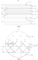
- 100-Multilayer composite electrode sheet 110-Positive current collector; 120-First lithium manganese iron phosphate layer; 130-Second lithium manganese iron phosphate layer; 140-Third lithium manganese iron phosphate layer; 150-First conductive fiber; 160-Second conductive fiber; 170-Needle injection apparatus.
- orientations or positional relationships indicated by the terms “on”, “below”, “left”, “right”, “front”, “back”, “top”, “bottom”, “inside”, “outside”, “vertical”, “horizontal”, “lateral”, “longitudinal”, etc. are orientations or positional relationships shown based on the accompanying drawings. These terms are used primarily to better describe the present disclosure and the embodiments thereof and are not intended to limit that the indicated apparatuses, elements or components have to be located at specific orientations, or to be constructed and operated in the specific orientations.
- the terms “installed”, “set”, “provided”, “connected”, and “linked” can be understood in a broad sense.
- it may be a fixed connection, a detachable connection, or an integral construction; it may be a mechanical connection or an electrical connection; it may be a direct connection, or an indirect connection through an intermediate medium, or an internal communication between two apparatuses, elements or components.
- installed may be a fixed connection, a detachable connection, or an integral construction
- it may be a mechanical connection or an electrical connection
- it may be a direct connection, or an indirect connection through an intermediate medium, or an internal communication between two apparatuses, elements or components.
- the specific meanings of these terms in the present disclosure may be understood according to specific circumstances.
- first means two or more.
- Lithium manganese iron phosphate has the same material safety property as lithium iron phosphate, and the capacity per gram of lithium manganese iron phosphate and that of lithium iron phosphate are equal, both are 170mAh/g.
- lithium manganese iron phosphate has a higher voltage platform. Therefore, the energy density of lithium manganese iron phosphate is higher than that of lithium iron phosphate.
- a positive electrode sheet is prepared as a multilayer composite electrode sheet.
- a positive electrode slurry is sequentially coated on the positive current collector to form a plurality of lithium manganese iron phosphate layers, which results in a relatively large internal resistance of the formed multilayer composite electrode sheet due to the existence of a connecting interface between every two adjacent lithium manganese iron phosphate layers.
- the present disclosure provides a multilayer composite electrode sheet, an energy storage apparatus and a preparation method.
- first conductive fibers between a first lithium manganese iron phosphate layer and a second lithium manganese iron phosphate layer and inserting the first conductive fibers into the first lithium manganese iron phosphate layer and the second lithium manganese iron phosphate layer respectively in a direction that forms a first acute angle R1 with the first direction
- not only the connection stability between the first lithium manganese iron phosphate layer and the second lithium manganese iron phosphate layer can be improved due to the first acute angle R1 formed between the first conductive fiber and the first direction, but also the interface resistance between the first lithium manganese iron phosphate layer and the second lithium manganese iron phosphate layer can be reduced due to the conductive ability of the first conductive fibers.
- an embodiment of the present application provides a multilayer composite electrode sheet 100.
- the multilayer composite electrode sheet 100 comprises a positive current collector 110, a first lithium manganese iron phosphate layer 120, a second lithium manganese iron phosphate layer 130, a third lithium manganese iron phosphate layer 140, first conductive fibers 150 and second conductive fibers 160.
- the first lithium manganese iron phosphate layer 120 is disposed on the positive current collector 110.
- the second lithium manganese iron phosphate layer 130 is disposed on a surface of the first lithium manganese iron phosphate layer 120 facing away from the positive current collector 110.
- the third lithium manganese iron phosphate layer 140 is disposed on a surface of the second lithium manganese iron phosphate layer 130 facing away from the positive current collector 110.
- One end of the first conductive fiber 150 is inserted obliquely into the surface of the first lithium manganese iron phosphate layer 120 facing away from the positive current collector 110, and the other end of the first conductive fiber 150 is inserted obliquely into a surface of the second lithium manganese iron phosphate layer 130 facing toward the positive current collector 110.
- the first conductive fibers 150 extend along a direction that forms a first acute angle R1 with a first direction
- the second conductive fibers 160 extend along a direction that forms a second acute angle R2 with the first direction
- the first direction is a direction in which the positive current collector 110 points to the first lithium manganese iron phosphate layer 120.
- the first conductive fibers 150 are provided between the first lithium manganese iron phosphate layer 120 and the second lithium manganese iron phosphate layer 130, where one end of the first conductive fiber 150 is inserted into the surface of the first lithium manganese iron phosphate layer 120 facing away from the positive current collector 110, and the other end of the first conductive fiber 150 is inserted into the surface of the second lithium manganese iron phosphate layer 130 facing toward the positive current collector 110.
- the second conductive fibers 160 are provided between the second lithium manganese iron phosphate layer 130 and the third lithium manganese iron phosphate layer 140, where one end of the second conductive fiber 160 is inserted into the surface of the second lithium manganese iron phosphate layer 130 facing away from the positive current collector 110, and the other end of the second conductive fiber 160 is inserted into the surface of the third lithium manganese iron phosphate layer 140 facing toward the positive current collector 110.
- the first lithium manganese iron phosphate layer 120 and the second lithium manganese iron phosphate layer 130 compared with the second lithium manganese iron phosphate layer 130 being directly attached to the first lithium manganese iron phosphate layer 120, it enables the first lithium manganese iron phosphate layer 120 and the second lithium manganese iron phosphate layer 130 to be connected to each other through the first conductive fibers 150, thereby improving the connection stability between the first lithium manganese iron phosphate layer 120 and the second lithium manganese iron phosphate layer 130.
- the second lithium manganese iron phosphate layer 130 and the third lithium manganese iron phosphate layer 140 to be connected to each other through the second conductive fibers 160, thereby improving the connection stability between the second lithium manganese iron phosphate layer 130 and the third lithium manganese iron phosphate layer 140. Therefore, the structural strength of the multilayer composite electrode sheet 100 is improved.
- conductive fibers are made of chemical fibers, metal wires or carbon fibers with conductive media, etc. Therefore, by inserting one end of the first conductive fiber 150 into the surface of the first lithium manganese iron phosphate layer 120 facing away from the positive current collector 110 and inserting the other end into the surface of the second lithium manganese iron phosphate layer 130 facing toward the positive current collector 110, and by inserting one end of the second conductive fiber 160 into the surface of the second lithium manganese iron phosphate layer 130 facing away from the positive current collector 110 and inserting the other end into the surface of the third lithium manganese iron phosphate layer 140 facing toward the positive current collector 110, the interface resistance between the first lithium manganese iron phosphate layer 120 and the second lithium manganese iron phosphate layer 130 can be reduced, and the interface resistance between the second lithium manganese iron phosphate layer 130 and the third lithium manganese iron phosphate layer 140 can also be reduced.
- the internal resistance of the multilayer composite electrode sheet 100 is reduced, thereby improving the electrochemical performance
- the pulling force exerted on the first lithium manganese iron phosphate layer 120 by the portion of the first conductive fibers 150 inserted into the first lithium manganese iron phosphate layer 120 has a component force in a direction along the layer surface of the first lithium manganese iron phosphate layer 120 and a component force in the first direction.
- connection strength between the first conductive fibers 150 and the first lithium manganese iron phosphate layer 120 is improved, and similarly, the connection strength between the first conductive fibers 150 and the second lithium manganese iron phosphate layer 130 is improved, thereby further improving the connection stability between the first lithium manganese iron phosphate layer 120 and the second lithium manganese iron phosphate layer 130.
- the strength of the connection between the second conductive fibers 160 and the second lithium manganese iron phosphate layer 130 as well as the third lithium manganese iron phosphate layer 140 are enhanced. Therefore, the structural strength of the multilayer composite electrode sheet 100 is further improved.
- the above-mentioned multilayer composite electrode sheet 100 refers to an electrode sheet with multiple lithium manganese iron phosphate layers provided on the positive current collector 110, that is, three or more lithium manganese iron phosphate layers are formed sequentially on the positive current collector 110, and conductive fibers are provided between every two adjacent lithium manganese iron phosphate layers.
- the above-mentioned first lithium manganese iron phosphate layer 120, second lithium manganese iron phosphate layer 130 and third lithium manganese iron phosphate layer 140 can not be understood as a limitation on the number of lithium manganese iron phosphate layers in the multilayer composite electrode sheet 100.
- first conductive fibers 150 and the second conductive fibers 160 can not be understood as a limitation on the number of layers of conductive fibers in the multilayer composite electrode sheet 100.
- the number of layers of conductive fibers is related to the number of lithium manganese iron phosphate layers, i.e., the greater the number of lithium manganese iron phosphate layers, for example, a fourth lithium manganese iron phosphate layer, a fifth lithium manganese iron phosphate layer, etc., then the corresponding conductive fibers also comprise a third conductive fiber, fourth conductive fibers, etc.
- the above-mentioned first direction refers to the direction perpendicular to the layer surface of the first lithium manganese iron phosphate layer 120, i.e., the direction indicated by the arrow X in FIG. 1 , that is, the direction in which the positive current collector 110 points to the first lithium manganese iron phosphate layer 120, or the direction in which the first lithium manganese iron phosphate layer 120 points to the positive current collector 110, or the direction in which the first lithium manganese iron phosphate layer 120 points to the second lithium manganese iron phosphate layer 130, or the direction in which the second lithium manganese iron phosphate layer 130 points to the third lithium manganese iron phosphate layer 140, etc.
- first acute angle R1 and the second acute angle R2 may be equal or different, which is not limited herein.
- first conductive fibers there are a plurality of first conductive fibers and a plurality of second conductive fibers.
- the plurality of first conductive fibers 150 are distributed at intervals on the surface of the first lithium manganese iron phosphate layer 120 facing away from the positive current collector 110. And the greater the number of the first conductive fibers 150, the smaller the spacing between every two adjacent first conductive fibers 150, and the more significant effect on improving the interface resistance between the first lithium manganese iron phosphate layer 120 and the second lithium manganese iron phosphate layer 130 by the first conductive fibers 150.
- the plurality of second conductive fibers 160 are distributed at intervals on the surface of the second lithium manganese iron phosphate layer 130 facing away from the positive current collector 110.
- first conductive fibers 150 and the spacing between every two adjacent first conductive fibers 150 are not limited herein, and the number of second conductive fibers 160 and the spacing between every two adjacent second conductive fibers 160 are not limited herein, both of which may be designed by those skilled in the art according to the extent to which the structural strength and interface resistance of the multilayer composite electrode sheet 100 are improved by the first conductive fibers and the second conductive fibers 160, respectively.
- the first acute angle R1 and the second acute angle R2 are both in a range between 25° and 55°.
- the component force of the first conductive fibers 150 or the second conductive fibers 160 in the direction along the layer surface of the first lithium manganese iron phosphate layer 120 is relatively small, thereby affecting the pulling force exerted on the first lithium manganese iron phosphate layer 120 or the second lithium manganese iron phosphate layer 130 by the first conductive fibers 120 in the direction along the layer surface of the first lithium manganese iron phosphate layer 120, or, affecting the pulling force exerted on the second lithium manganese iron phosphate layer 130 or the third lithium manganese iron phosphate layer 140 by the second conductive fibers 160 in the direction along the layer surface of the first lithium manganese iron phosphate layer 120, thus the structural strength of the multilayer composite electrode sheet 100 is affected.
- the component force of the first conductive fibers 150 or the second conductive fibers 160 in the first direction is relatively small, thereby affecting the pulling force exerted on the first lithium manganese iron phosphate layer 120 or the second lithium manganese iron phosphate layer 130 by the first conductive fibers 150 in the first direction, or, affecting the pulling force exerted on the second lithium manganese iron phosphate layer 130 or the third lithium manganese iron phosphate layer 140 by the second conductive fibers 160 in the first direction, thus the connection stability between the plurality of lithium manganese iron phosphate layers in the multilayer composite electrode sheet 100 are affected.
- the first acute angle R1 and the second acute angle R2 are set between 25° and 55°, which can not only ensure the structural strength of the multilayer composite electrode sheet 100, but also improve the connection stability between the plurality of lithium manganese iron phosphate layers.
- the first acute angle R1 is 25°, 28°, 30°, 35°, 38°, 40°, 45°, 48°, 50°, 55°, etc.
- the first acute angle R1 and the second acute angle R2 are 45°, the component force in the first direction and the component force in the direction along the layer surface of the first lithium manganese iron phosphate layer 120 provided by the first conductive fibers 150 and the second conductive fibers 160 are the same.
- the first conductive fibers 150 and the second conductive fibers 160 provide a better effect on improving the structural strength of the multilayer composite electrode sheet 100 and the connection stability between the plurality of lithium manganese iron phosphate layers.
- a cross sectional plane of the stacked first lithium manganese iron phosphate layer 120 and second lithium manganese iron phosphate layer 130 in the first direction is a first section (the area shown by A1 in FIG. 1 ), and projections of at least two of the first conductive fibers 150 on the first section are in a crossed state; and a cross sectional plane of the stacked second lithium manganese iron phosphate layer 130 and third lithium manganese iron phosphate layer 140 in the first direction is a second section (the area shown by A2 in FIG. 1 ), and projections of at least two of the second conductive fibers on the second section are in a crossed state.
- the projections of at least two of the first conductive fibers 150 on the first section and the projections of at least two of the second conductive fibers 160 on the second cross section are both in the crossed state, which can improve the structural strength of the first conductive fibers 150 and the second conductive fibers 160, thereby improving the bonding strength between the first lithium manganese iron phosphate layer 120 and the second lithium manganese iron phosphate layer 130, and the bonding strength between the second lithium manganese iron phosphate layer 130 and the third lithium manganese iron phosphate layer 140.
- the projections of at least two of the first conductive fibers 150 on the first section are in the crossed state. It can be understood that along the width direction of the multilayer composite electrode sheet 100, every two adjacent first conductive fibers 150 in the plurality of first conductive fibers 150 are arranged to be mirrored with the first direction as a reference line, and every two adjacent first conductive fibers 150 intersect at a position near the middle in the extending directions thereof, that is, the plurality of first conductive fibers 150 form a cross-woven conductive fiber layer in the width direction of the multilayer composite electrode sheet 100.
- the cross arrangement of the second conductive fibers 160 is the same as the cross arrangement of the first conductive fibers 150, and will not be repeated herein.
- an insertion depth of the first conductive fibers 150 into the first lithium manganese iron phosphate layer 120 is the same as an insertion depth of the first conductive fibers 150 into the second lithium manganese iron phosphate layer 130; and/or an insertion depth of the second conductive fibers into the second lithium manganese iron phosphate layer 130 is the same as an insertion depth of the second conductive fibers into the third lithium manganese iron phosphate layer 140 (i.e., the insertion depth of the first conductive fibers 150 into the first lithium manganese iron phosphate layer 120 is the same as the insertion depth of the first conductive fibers 150 into the second lithium manganese iron phosphate layer 130, the insertion depth of the second conductive fibers into the second lithium manganese iron phosphate layer 130 is the same as the insertion depth of the second conductive fibers into the third lithium manganese iron phosphate layer 140, or the insertion depth of the first conductive fibers 150
- the above-mentioned insertion depth refers to the distance by which the first conductive fibers 150 extends into the first lithium manganese iron phosphate layer 120 and the second lithium manganese iron phosphate layer 130 in the first direction, and/or the distance by which the second conductive fibers 160 extends into the second lithium manganese iron phosphate layer 130 and the third lithium manganese iron phosphate layer 140 in the first direction (i.e., the above-mentioned insertion depth refers to the distance by which the first conductive fibers 150 extends into the first lithium manganese iron phosphate layer 120 and the second lithium manganese iron phosphate layer 130 in the first direction, the above-mentioned insertion depth refers to the distance by which the second conductive fibers 160 extends into the second lithium manganese iron phosphate layer 130 and the third lithium manganese iron phosphate layer 140 in the first direction, or the above-mentioned insertion depth refers to the distance by which the first conductive fibers 150 extends
- the first conductive fibers 150 When the first conductive fibers 150 are inserted into the first lithium manganese iron phosphate layer 120 at the same depth as they are inserted into the second lithium manganese iron phosphate layer 130, it can enable the pulling force exerted on the first lithium manganese iron phosphate layer 120 by the first conductive fibers 150 to be equal to the pulling force exerted on the second lithium manganese iron phosphate layer 130 by the first conductive fibers 150.
- step 200 first conductive fibers are inserted into a surface of the first lithium manganese iron phosphate layer facing away from the positive current collector in a direction that forms a first acute angle R1 with a first direction, and a portion of the first conductive fiber is made protrude from the surface of the first lithium manganese iron phosphate layer facing away from the positive current collector.
- the first conductive fibers 150 are first dissolved in N-methylpyrrolidone, and then a uniformly mixed slurry of the first conductive fibers 150 is obtained by stirring for a certain period of time. Then, an auxiliary apparatus is used to insert the slurry of the first conductive fibers 150 into the surface of the first lithium manganese iron phosphate layer 120 facing away from the positive current collector 110 in the direction that forms a first acute angle R1 with the first direction, and a portion of the first conductive fiber 150 is made protrude from the surface of the first lithium manganese iron phosphate layer 120 facing away from the positive current collector 110 as shown in FIG. 8 .
- step S300 a positive electrode slurry is coated on a side of the first lithium manganese iron phosphate layer into which the first conductive fibers are inserted, to form a second lithium manganese iron phosphate layer, so that the first conductive fibers protruding from the first lithium manganese iron phosphate layer are inserted into the second lithium manganese iron phosphate layer in the direction that forms the first acute angle R1 with the first direction.
- lithium manganese iron phosphate LiMnxFe1-xPO4 and 0.4 ⁇ x ⁇ 0.6
- conductive carbon black conductive carbon black
- polyvinylidene fluoride are firstly weighed with a mass ratio of 95%:2%:3% and put into a stirred tank, and an appropriate amount of N-methylpyrrolidone is added to the stirred tank.
- the stirred tank is then started to stir for a certain period of time, for example, 6 hours to obtain a second slurry with an appropriate viscosity.
- the second slurry is uniformly coated on the first lithium manganese iron phosphate layer 120 through an extrusion manner to form the second lithium manganese iron phosphate layer 130 as shown in FIG. 9 .
- step S400 the second conductive fibers are inserted into the surface of the second lithium manganese iron phosphate layer facing away from the positive current collector in the direction that forms the second acute angle R2 with the first direction, and a portion of the second conductive fiber is made protrude from the surface of the second lithium manganese iron phosphate layer facing away from the positive current collector.
- step 500 a positive electrode slurry is coated on a side of the second lithium manganese iron phosphate layer into which the second conductive fibers are inserted, to form the third lithium manganese iron phosphate layer, so that the second conductive fibers protruding from the second lithium manganese iron phosphate layer are inserted into the third lithium manganese iron phosphate layer in the direction that forms the second acute angle R2 with the first direction.
- lithium manganese iron phosphate LiMnxFe1-xPO4 and 0.2 ⁇ x ⁇ 0.4
- conductive carbon black conductive carbon black
- polyvinylidene fluoride are firstly weighed with a mass ratio of 95%:2%:3% and put into a stirred tank, and an appropriate amount of N-methylpyrrolidone is added to the stirred tank.
- the stirred tank is then started to stir for a certain period of time, for example, 6 hours to obtain a third slurry with an appropriate viscosity.
- the third slurry is uniformly coated on the second lithium manganese iron phosphate layer 130 through an extrusion manner to form the third lithium manganese iron phosphate layer 140 as shown in FIG. 11 .
- the surface of the second lithium manganese iron phosphate layer 130 facing away from the positive current collector 110 is provided with the second conductive fiber 160 that forms the second acute angle R2 with the first direction, and a portion of the second conductive fiber 160 protrudes from the second lithium manganese iron phosphate layer 130. Therefore, the second conductive fibers 160 protruding from the second lithium manganese iron phosphate layer 130 will be inserted into the third lithium manganese iron phosphate layer 140 in the direction that forms the second acute angle R2 with the first direction.
- first conductive fibers 150 forming a first acute angle R1 with the first direction are disposed on the first lithium manganese iron phosphate layer 120.
- second conductive fibers 160 forming a second acute angle R2 with the first direction are disposed on the second lithium manganese iron phosphate layer 130.
- the first lithium manganese iron phosphate layer 120 and the second lithium manganese iron phosphate layer 130 compared with the second lithium manganese iron phosphate layer 130 being directly attached to the first lithium manganese iron phosphate layer 120, it enables the first lithium manganese iron phosphate layer 120 and the second lithium manganese iron phosphate layer 130 to be connected to each other through the first conductive fibers 150, thereby improving the connection stability between the first lithium manganese iron phosphate layer 120 and the second lithium manganese iron phosphate layer 130.
- the second lithium manganese iron phosphate layer 130 and the third lithium manganese iron phosphate layer 140 to be connected to each other through the second conductive fibers 160, thereby improving the connection stability between the second lithium manganese iron phosphate layer 130 and the third lithium manganese iron phosphate layer 140. Therefore, the structural strength of the multilayer composite electrode sheet 100 is improved.
- conductive fibers are made of chemical fibers, metal wires or carbon fibers with conductive media, etc. Therefore, the interface resistance between the first lithium manganese iron phosphate layer 120 and the second lithium manganese iron phosphate layer 130 can be reduced through the first conductive fibers 150 and the interface resistance between the second lithium manganese iron phosphate layer 130 and the third lithium manganese iron phosphate layer 140 can be reduced through the second conductive fibers 160.
- the internal resistance of the multilayer composite electrode sheet 100 is reduced, thereby improving the electrochemical performance of the energy storage apparatus formed by the multilayer composite electrode sheet 100.
- the pulling force exerted on the first lithium manganese iron phosphate layer 120 by the portion of the first conductive fibers 150 inserted into the first lithium manganese iron phosphate layer 120 has a component force in a direction along the layer surface of the first lithium manganese iron phosphate layer 120 and a component force in the first direction.
- connection strength between the first conductive fibers 150 and the first lithium manganese iron phosphate layer 120 is improved, and similarly, the connection strength between the first conductive fibers 150 and the second lithium manganese iron phosphate layer 130 is improved, thereby improving the connection stability between the first lithium manganese iron phosphate layer 120 and the second lithium manganese iron phosphate layer 130.
- connection strength between the second conductive fibers 160 and the second lithium manganese iron phosphate layer 130 as well as the third lithium manganese iron phosphate layer 140 are enhanced. Therefore, the structural strength of the multilayer composite electrode sheet 100 is further improved.
- the preparation method comprises: injecting one end of the first conductive fiber 150 into the surface of the first lithium manganese iron phosphate layer 120 facing away from the positive current collector 110 in the direction that forms the first acute angle R1 with the first direction by using a needle injection apparatus 170.
- the injection volume, the movement speed, and the injection frequency of the needle injection apparatus 170 are controlled to extend the slurry of the first conductive fibers 150 into the interior of the first lithium manganese iron phosphate layer 120 so as to insert the first conductive fibers 150 into the interior of the first lithium manganese iron phosphate layer 120.
- the operation process of injecting the first conductive fibers 150 into the first lithium manganese iron phosphate layer 120 by using the needle injection apparatus 170 is simple and the operation efficiency is high.
- the preparation method comprises: injecting, by the needle injection apparatus 170, the first conductive fibers 150 in a state where the first lithium manganese iron phosphate layer 120 is not completely dry.
- the first lithium manganese iron phosphate layer 120 in an incompletely dried state is relatively soft, which enables the first conductive fibers 150 to be inserted into the first lithium manganese iron phosphate layer 120 with less resistance, thereby facilitating the formation of the first conductive fibers 150 in the crossed state.
- the humidity of the first lithium manganese iron phosphate layer 120 in the incompletely dried state is around 30%, for example, the humidity of the first lithium manganese iron phosphate layer 120 in the incompletely dried state is 30%, 31%, etc.
- the injection of the second conductive fibers 160 is carried out when the second lithium manganese iron phosphate layer 130 is in an incompletely dried state.
- the inserting the second conductive fibers 160 into the surface of the second lithium manganese iron phosphate layer 130 facing away from the positive current collector 110 in the direction that forms the second acute angle R2 with the first direction comprises: injecting one end of the second conductive fiber 160 into the surface of the second lithium manganese iron phosphate layer 130 facing away from the positive current collector 110 in the direction that forms the second acute angle R2 with the first direction by using the needle injection apparatus 170.
- the principle of inserting the second conductive fibers 160 into the second lithium manganese iron phosphate layer 130 is the same as the principle of inserting the first conductive fibers 150 into the first lithium manganese iron phosphate layer 120, and details may refer to the above description, which will not be repeated herein.
- the preparation method of injecting one end of the first conductive fiber 150 into the surface of the first lithium manganese iron phosphate layer 120 facing away from the positive current collector 110 in the direction that forms the first acute angle R1 with the first direction by using the needle injection apparatus 170 comprises the following steps.
- step S210 two groups of the needle injection apparatuses are provided.
- each group of needle injection apparatuses 170 may inject multiple first conductive fibers 150 simultaneously, which improves the efficiency of arranging the first conductive fibers 150.
- step S220 the injection directions of the two groups of the needle injection apparatuses are adjusted to be mirrored with respect to the first direction, so that the injection directions of both groups of needle injection apparatuses form the first acute angle R1 with the first direction.
- the injection directions of the needle injection apparatuses 170 are first adjusted, either manually or automatically, until the injection directions of the needle injection apparatus 170 form a first acute angle R1 with the first direction, where the first acute angle R1 may be understood as an acute angle or an obtuse angle.
- step S230 the first conductive fibers that form the first acute angle R1 with the first direction are injected into the surface of the first lithium manganese iron phosphate layer facing away from the positive current collector by using the two groups of the needle injection apparatuses, respectively.
- the two groups of needle injection apparatuses 170 with the injection directions adjusted are moved to directly above the area where the first lithium manganese iron phosphate layer 120 is to be provided with the first conductive fibers 150.
- the needle injection apparatus 170 comprises a storage bin that is communicated with the injection head and is used to store the slurry of the first conductive fibers 150.
- the slurry of the first conductive fibers 150 in the storage bin will be injected into the first lithium manganese iron phosphate layer 120 through the injection head.
- the first lithium manganese iron phosphate layer 120 provided with the first conductive fibers 150 is then sufficiently dried by an oven (the drying temperature of the oven is about 120°C, and the drying time is about 5 hours) to form the first lithium manganese iron phosphate layer 120 with a special distribution of the first conductive fibers 150.
- the pulling force exerted on the first lithium manganese iron phosphate layer 120 by the portion of the first conductive fibers 150 inserted into the first lithium manganese iron phosphate layer 120 has a component force in a direction along the layer surface of the first lithium manganese iron phosphate layer 120 and a component force in the first direction.
- connection strength between the first conductive fibers 150 and the first lithium manganese iron phosphate layer 120 is improved, and similarly, the connection strength between the first conductive fibers 150 and the second lithium manganese iron phosphate layer 130 is improved, thereby improving the connection stability between the first lithium manganese iron phosphate layer 120 and the second lithium manganese iron phosphate layer 130.
- the injection directions of the two groups of needle injection apparatuses 170 are adjusted respectively, so that the injection directions of the two groups of the needle injection apparatuses 170 are symmetrical with respect to the first direction, and the symmetry herein refers to approximately symmetry.
- the component force of the first conductive fibers 150 or the second conductive fibers 160 in the direction along the layer surface of the first lithium manganese iron phosphate layer 120 is smaller, thereby affecting the pulling force exerted on the first lithium manganese iron phosphate layer 120 or the second lithium manganese iron phosphate layer 130 by the first conductive fibers 150 in the direction along the layer surface of the first lithium manganese iron phosphate layer 120, or, affecting the pulling force exerted on the second lithium manganese iron phosphate layer 130 or the third lithium manganese iron phosphate layer 140 by the second conductive fibers 160 in the direction along the layer surface of the first lithium manganese iron phosphate layer 120, thus the structural strength of the multilayer composite electrode sheet 100 is affected.
- angles between the injection direction of both groups of needle injection apparatuses 170 and the first direction are set between 25° and 55°, which can not only ensure the structural strength of the multilayer composite electrode sheet 100, but also improve the connection stability between the plurality of lithium manganese iron phosphate layers.
- an embodiment of the present application further provides a preparation method of an energy storage apparatus, where the preparation method comprises the following steps.
- step S 10 a positive electrode sheet is prepared.
- the positive electrode sheet is prepared by using the preparation method of the multilayer composite electrode sheet 100 in the above embodiment, and details may refer to the description in the above embodiment, which will not be repeated herein.
- step S20 a negative electrode sheet and a separator are provided.
- step S30 the positive electrode sheet, the separator and the negative electrode sheet are assembled and wound to form a wound electrode assembly.
- step S40 a end cap assembly is provided and connected to the wound electrode assembly.
- step S50 a housing is provided, the wound electrode assembly is installed into the housing, and the end cap assembly is welded and fixed to the housing.
- step S60 an electrolyte is provided, the electrolyte is injected into the interior of the housing and encapsulated after battery formation.
- step S70 an outer film is provided to wrap an outer peripheral wall of the housing to form an energy storage apparatus cell.
- the energy storage apparatus prepared by the above preparation method of the energy storage apparatus has a high energy density and better overall performance.
- the button battery is assembled for testing.
- the specific process of assembling the button battery is as follows: first, the positive electrode sheet and the negative electrode sheet are put into a press machine respectively to be pressed, so that the vacuum bubbles in the positive electrode sheet and the negative electrode sheet are eliminated. Then, the pressed positive electrode sheet and negative electrode sheet are cut to form a positive electrode disc with a first preset diameter and a negative electrode disc with a second preset diameter (where the first preset diameter is smaller than the second preset diameter). The positive electrode sheet and the negative electrode sheet are cut by using a punch machine, respectively.
- the diameter of the positive electrode disc is 15mm, i.e., the first preset diameter is 15mm, and the diameter of the negative electrode disc is 18mm, i.e., the second preset diameter is 18mm.
- the positive electrode disc and negative electrode disc are assembled in a glove box filled with protective gas (e.g., argon), and the positive electrode disc, negative electrode disc, polyethylene separator and other components are assembled together and then injected with electrolyte to form an energy storage apparatus.
- the electrolyte refers to a solution obtained by using 1 mol/L lithium hexafluorophosphate dissolved in a mixed solvent of ethylene carbonate and diethyl carbonate with a molar ratio of 1:1.
- An embodiment of the present application further provides an energy storage apparatus, which comprises the multilayer composite electrode sheet 100 in the above embodiment.
- the energy storage apparatus may be a lithium battery, a button battery, a power battery and the like.
- the above-mentioned energy storage apparatus may also be prepared and formed by using the above-mentioned preparation method of the energy storage apparatus.
- the energy storage apparatus has a high energy density and good overall performance.
Landscapes
- Chemical & Material Sciences (AREA)
- Chemical Kinetics & Catalysis (AREA)
- Electrochemistry (AREA)
- General Chemical & Material Sciences (AREA)
- Engineering & Computer Science (AREA)
- Inorganic Chemistry (AREA)
- Manufacturing & Machinery (AREA)
- Materials Engineering (AREA)
- Composite Materials (AREA)
- Crystallography & Structural Chemistry (AREA)
- Battery Electrode And Active Subsutance (AREA)
- Secondary Cells (AREA)
Applications Claiming Priority (1)
| Application Number | Priority Date | Filing Date | Title |
|---|---|---|---|
| CN202310681246.9A CN116417575B (zh) | 2023-06-09 | 2023-06-09 | 多层复合极片、储能装置及制备方法 |
Publications (2)
| Publication Number | Publication Date |
|---|---|
| EP4478437A1 true EP4478437A1 (de) | 2024-12-18 |
| EP4478437B1 EP4478437B1 (de) | 2026-04-29 |
Family
ID=87054668
Family Applications (1)
| Application Number | Title | Priority Date | Filing Date |
|---|---|---|---|
| EP24179150.8A Active EP4478437B1 (de) | 2023-06-09 | 2024-05-30 | Mehrschichtige verbundelektrodenfolie, energiespeichervorrichtung und herstellungsverfahren |
Country Status (4)
| Country | Link |
|---|---|
| US (1) | US20240413310A1 (de) |
| EP (1) | EP4478437B1 (de) |
| CN (1) | CN116417575B (de) |
| WO (1) | WO2024250734A1 (de) |
Families Citing this family (1)
| Publication number | Priority date | Publication date | Assignee | Title |
|---|---|---|---|---|
| CN116417575B (zh) * | 2023-06-09 | 2024-01-26 | 深圳海辰储能控制技术有限公司 | 多层复合极片、储能装置及制备方法 |
Citations (4)
| Publication number | Priority date | Publication date | Assignee | Title |
|---|---|---|---|---|
| US20170256788A1 (en) * | 2014-09-11 | 2017-09-07 | Toyota Jidosha Kabushiki Kaisha | Nonaqueous electrolyte secondary battery |
| CN113948673A (zh) * | 2021-10-13 | 2022-01-18 | 天津市捷威动力工业有限公司 | 一种锂离子电池正极片及其制备方法与锂离子电池 |
| US20220416251A1 (en) * | 2021-04-26 | 2022-12-29 | Panasonic Intellectual Property Management Co., Ltd. | Electrode layer and all-solid-state battery |
| CN116417567A (zh) * | 2023-06-09 | 2023-07-11 | 深圳海辰储能控制技术有限公司 | 正极极片、储能装置及制备方法 |
Family Cites Families (13)
| Publication number | Priority date | Publication date | Assignee | Title |
|---|---|---|---|---|
| FR2943854B1 (fr) * | 2009-03-26 | 2011-06-10 | Commissariat Energie Atomique | Batterie bipolaire a fonctionnement ameliore |
| JP2011175918A (ja) * | 2010-02-25 | 2011-09-08 | Jx Nippon Mining & Metals Corp | リチウムイオン二次電池用集電体、二次電池用負極及びリチウムイオン二次電池 |
| CN103094619B (zh) * | 2013-01-17 | 2015-02-04 | 北京好风光储能技术有限公司 | 一种高能量密度锂离子电池电芯及其制备方法 |
| WO2015093411A1 (ja) * | 2013-12-20 | 2015-06-25 | 三洋化成工業株式会社 | リチウムイオン電池用電極、リチウムイオン電池及びリチウムイオン電池用電極の製造方法 |
| CN107871868A (zh) * | 2016-09-26 | 2018-04-03 | 华为技术有限公司 | 一种石墨烯增强的一体化电极及其制备方法和电池 |
| CN109088050B (zh) * | 2018-06-26 | 2021-02-02 | 宁德新能源科技有限公司 | 极片及其锂离子电池 |
| CN115621412B (zh) * | 2021-07-15 | 2024-10-11 | 比亚迪股份有限公司 | 锂离子电池正极片、制备方法及锂离子电池 |
| CN113594415B (zh) * | 2021-07-28 | 2022-06-17 | 贵州大学 | 抑制锂硫电池穿梭效应的三明治独立正极及其制备方法 |
| CN115394959A (zh) * | 2022-09-05 | 2022-11-25 | 重庆立弘时代新材料有限公司 | 一种3d双层锂负极及其制备方法及全固态锂离子电池 |
| CN115207278B (zh) * | 2022-09-13 | 2022-12-20 | 深圳海润新能源科技有限公司 | 负极极片、其制备方法、电池及用电设备 |
| CN115458707B (zh) * | 2022-10-26 | 2025-09-16 | 欣旺达动力科技股份有限公司 | 二次电池及用电设备 |
| CN116137330B (zh) * | 2023-02-28 | 2026-04-17 | 上海恩捷新材料科技有限公司 | 集流体及其制备方法、电池极片和电池 |
| CN116417575B (zh) * | 2023-06-09 | 2024-01-26 | 深圳海辰储能控制技术有限公司 | 多层复合极片、储能装置及制备方法 |
-
2023
- 2023-06-09 CN CN202310681246.9A patent/CN116417575B/zh active Active
-
2024
- 2024-02-18 WO PCT/CN2024/077392 patent/WO2024250734A1/zh not_active Ceased
- 2024-05-22 US US18/671,422 patent/US20240413310A1/en active Pending
- 2024-05-30 EP EP24179150.8A patent/EP4478437B1/de active Active
Patent Citations (4)
| Publication number | Priority date | Publication date | Assignee | Title |
|---|---|---|---|---|
| US20170256788A1 (en) * | 2014-09-11 | 2017-09-07 | Toyota Jidosha Kabushiki Kaisha | Nonaqueous electrolyte secondary battery |
| US20220416251A1 (en) * | 2021-04-26 | 2022-12-29 | Panasonic Intellectual Property Management Co., Ltd. | Electrode layer and all-solid-state battery |
| CN113948673A (zh) * | 2021-10-13 | 2022-01-18 | 天津市捷威动力工业有限公司 | 一种锂离子电池正极片及其制备方法与锂离子电池 |
| CN116417567A (zh) * | 2023-06-09 | 2023-07-11 | 深圳海辰储能控制技术有限公司 | 正极极片、储能装置及制备方法 |
Also Published As
| Publication number | Publication date |
|---|---|
| CN116417575B (zh) | 2024-01-26 |
| WO2024250734A1 (zh) | 2024-12-12 |
| US20240413310A1 (en) | 2024-12-12 |
| CN116417575A (zh) | 2023-07-11 |
| EP4478437B1 (de) | 2026-04-29 |
Similar Documents
| Publication | Publication Date | Title |
|---|---|---|
| EP1698004B1 (de) | Positiv-elektrodenmaterial für eine lithiumionenbatterie mit wasserfreiem elektrolyt und batterie damit | |
| US6203938B1 (en) | Flat cells | |
| EP3282502B1 (de) | Elektrode, elektrodengruppe und batterie mit wasserfreiem elektrolyt | |
| EP4478437A1 (de) | Mehrschichtige verbundelektrodenfolie, energiespeichervorrichtung und herstellungsverfahren | |
| US20220223982A1 (en) | Electrochemical device and electronic device containing the same | |
| CN113036069A (zh) | 一种提升锂电池容量和稳定性的方法、涂覆装置和用途 | |
| KR20200025056A (ko) | 원통형 삼전극 셀의 제조방법 및 이에 의해 제조된 원통형 삼전극 셀 | |
| US20250309497A1 (en) | Battery cell, manufacturing method therefor, battery, and power consuming apparatus | |
| US20240332760A1 (en) | Secondary battery and electronic device | |
| CN117637989A (zh) | 极片、电极组件及电池 | |
| CN116417567A (zh) | 正极极片、储能装置及制备方法 | |
| CN109494413B (zh) | 一种软包锂离子电池及其制备方法 | |
| EP4579817A1 (de) | Positivelektrodenfolie, sekundärbatterie und elektrische vorrichtung | |
| WO2024174760A1 (zh) | 正极片、储能装置及正极片的制作方法 | |
| JP3508455B2 (ja) | リチウムイオン電池用負極板及びその製造方法 | |
| CN101771174A (zh) | 硬壳聚合物锂离子电池 | |
| JP2011204670A (ja) | 非水電解質二次電池用正極及びその製造方法、並びに、当該正極を用いた非水電解質二次電池及びその製造方法 | |
| JP2019212609A (ja) | リチウム二次電池 | |
| CN113945477A (zh) | 一种电池电极材料中碳含量的检测方法 | |
| CN114243092A (zh) | 一种方形锂离子电池 | |
| US20250286076A1 (en) | Current collector and preparation apparatus thereof, electrode plate, battery, and electrical device | |
| CN114709469B (zh) | 电化学装置及电子装置 | |
| CN121663047B (zh) | 软包电池及用电装置 | |
| US20230395907A1 (en) | Secondary battery | |
| US20260121252A1 (en) | Secondary battery and electrical device |
Legal Events
| Date | Code | Title | Description |
|---|---|---|---|
| PUAI | Public reference made under article 153(3) epc to a published international application that has entered the european phase |
Free format text: ORIGINAL CODE: 0009012 |
|
| STAA | Information on the status of an ep patent application or granted ep patent |
Free format text: STATUS: THE APPLICATION HAS BEEN PUBLISHED |
|
| AK | Designated contracting states |
Kind code of ref document: A1 Designated state(s): AL AT BE BG CH CY CZ DE DK EE ES FI FR GB GR HR HU IE IS IT LI LT LU LV MC ME MK MT NL NO PL PT RO RS SE SI SK SM TR |
|
| RAP1 | Party data changed (applicant data changed or rights of an application transferred) |
Owner name: HITHIUM TECH HK LIMITED |
|
| STAA | Information on the status of an ep patent application or granted ep patent |
Free format text: STATUS: REQUEST FOR EXAMINATION WAS MADE |
|
| 17P | Request for examination filed |
Effective date: 20250606 |
|
| GRAP | Despatch of communication of intention to grant a patent |
Free format text: ORIGINAL CODE: EPIDOSNIGR1 |
|
| STAA | Information on the status of an ep patent application or granted ep patent |
Free format text: STATUS: GRANT OF PATENT IS INTENDED |
|
| RIC1 | Information provided on ipc code assigned before grant |
Ipc: H01M 4/04 20060101AFI20260103BHEP Ipc: H01M 4/136 20100101ALI20260103BHEP Ipc: H01M 4/1397 20100101ALI20260103BHEP Ipc: H01M 4/58 20100101ALI20260103BHEP Ipc: H01M 4/62 20060101ALI20260103BHEP Ipc: H01M 4/66 20060101ALI20260103BHEP Ipc: H01M 4/02 20060101ALN20260103BHEP Ipc: H01M 10/0525 20100101ALN20260103BHEP |
|
| INTG | Intention to grant announced |
Effective date: 20260126 |
|
| GRAS | Grant fee paid |
Free format text: ORIGINAL CODE: EPIDOSNIGR3 |
|
| GRAA | (expected) grant |
Free format text: ORIGINAL CODE: 0009210 |
|
| STAA | Information on the status of an ep patent application or granted ep patent |
Free format text: STATUS: THE PATENT HAS BEEN GRANTED |
|
| AK | Designated contracting states |
Kind code of ref document: B1 Designated state(s): AL AT BE BG CH CY CZ DE DK EE ES FI FR GB GR HR HU IE IS IT LI LT LU LV MC ME MK MT NL NO PL PT RO RS SE SI SK SM TR |
|
| REG | Reference to a national code |
Ref country code: CH Ref legal event code: F10 Free format text: ST27 STATUS EVENT CODE: U-0-0-F10-F00 (AS PROVIDED BY THE NATIONAL OFFICE) Effective date: 20260429 |