EP3282502B1 - Elektrode, elektrodengruppe und batterie mit wasserfreiem elektrolyt - Google Patents
Elektrode, elektrodengruppe und batterie mit wasserfreiem elektrolyt Download PDFInfo
- Publication number
- EP3282502B1 EP3282502B1 EP16776570.0A EP16776570A EP3282502B1 EP 3282502 B1 EP3282502 B1 EP 3282502B1 EP 16776570 A EP16776570 A EP 16776570A EP 3282502 B1 EP3282502 B1 EP 3282502B1
- Authority
- EP
- European Patent Office
- Prior art keywords
- organic fiber
- electrode
- containing layer
- thickness
- negative electrode
- Prior art date
- Legal status (The legal status is an assumption and is not a legal conclusion. Google has not performed a legal analysis and makes no representation as to the accuracy of the status listed.)
- Active
Links
- 239000011255 nonaqueous electrolyte Substances 0.000 title claims description 160
- 239000000835 fiber Substances 0.000 claims description 397
- 239000011244 liquid electrolyte Substances 0.000 claims description 102
- 239000002033 PVDF binder Substances 0.000 claims description 27
- 229920002981 polyvinylidene fluoride Polymers 0.000 claims description 27
- 239000004952 Polyamide Substances 0.000 claims description 6
- 239000004962 Polyamide-imide Substances 0.000 claims description 6
- 239000002131 composite material Substances 0.000 claims description 6
- 229920002647 polyamide Polymers 0.000 claims description 6
- 229920002312 polyamide-imide Polymers 0.000 claims description 6
- 239000004642 Polyimide Substances 0.000 claims description 5
- 229920001721 polyimide Polymers 0.000 claims description 5
- 239000004372 Polyvinyl alcohol Substances 0.000 claims description 4
- 229920002451 polyvinyl alcohol Polymers 0.000 claims description 4
- 239000001913 cellulose Substances 0.000 claims description 3
- 229920002678 cellulose Polymers 0.000 claims description 3
- 229920002239 polyacrylonitrile Polymers 0.000 claims description 3
- 229920000098 polyolefin Polymers 0.000 claims description 3
- SWAIALBIBWIKKQ-UHFFFAOYSA-N lithium titanium Chemical compound [Li].[Ti] SWAIALBIBWIKKQ-UHFFFAOYSA-N 0.000 claims description 2
- 150000002894 organic compounds Chemical class 0.000 claims description 2
- 239000010410 layer Substances 0.000 description 347
- 230000000052 comparative effect Effects 0.000 description 107
- 238000000034 method Methods 0.000 description 62
- 239000010408 film Substances 0.000 description 55
- 230000001681 protective effect Effects 0.000 description 48
- 238000005259 measurement Methods 0.000 description 35
- 238000007789 sealing Methods 0.000 description 26
- 238000003860 storage Methods 0.000 description 26
- 239000002904 solvent Substances 0.000 description 25
- 239000011230 binding agent Substances 0.000 description 21
- 229910052782 aluminium Inorganic materials 0.000 description 20
- XAGFODPZIPBFFR-UHFFFAOYSA-N aluminium Chemical compound [Al] XAGFODPZIPBFFR-UHFFFAOYSA-N 0.000 description 20
- 238000005470 impregnation Methods 0.000 description 19
- 239000005001 laminate film Substances 0.000 description 18
- -1 polytetrafluoroethylene Polymers 0.000 description 18
- 239000006258 conductive agent Substances 0.000 description 17
- 239000003792 electrolyte Substances 0.000 description 17
- 238000004519 manufacturing process Methods 0.000 description 13
- 239000000463 material Substances 0.000 description 13
- CSCPPACGZOOCGX-UHFFFAOYSA-N Acetone Chemical compound CC(C)=O CSCPPACGZOOCGX-UHFFFAOYSA-N 0.000 description 12
- 239000011888 foil Substances 0.000 description 12
- 230000001747 exhibiting effect Effects 0.000 description 10
- 239000002657 fibrous material Substances 0.000 description 10
- 239000007774 positive electrode material Substances 0.000 description 10
- OKTJSMMVPCPJKN-UHFFFAOYSA-N Carbon Chemical compound [C] OKTJSMMVPCPJKN-UHFFFAOYSA-N 0.000 description 9
- SECXISVLQFMRJM-UHFFFAOYSA-N N-Methylpyrrolidone Chemical compound CN1CCCC1=O SECXISVLQFMRJM-UHFFFAOYSA-N 0.000 description 9
- 239000012212 insulator Substances 0.000 description 9
- 229910052751 metal Inorganic materials 0.000 description 9
- 239000002184 metal Substances 0.000 description 9
- 229920005989 resin Polymers 0.000 description 9
- 239000011347 resin Substances 0.000 description 9
- 229910000838 Al alloy Inorganic materials 0.000 description 8
- WHXSMMKQMYFTQS-UHFFFAOYSA-N Lithium Chemical compound [Li] WHXSMMKQMYFTQS-UHFFFAOYSA-N 0.000 description 8
- 239000011267 electrode slurry Substances 0.000 description 8
- 229910052744 lithium Inorganic materials 0.000 description 8
- 239000000203 mixture Substances 0.000 description 8
- 239000007773 negative electrode material Substances 0.000 description 8
- 239000011248 coating agent Substances 0.000 description 7
- 238000000576 coating method Methods 0.000 description 7
- 238000012790 confirmation Methods 0.000 description 7
- 229910001416 lithium ion Inorganic materials 0.000 description 7
- 239000002002 slurry Substances 0.000 description 7
- 229920001577 copolymer Polymers 0.000 description 6
- JBTWLSYIZRCDFO-UHFFFAOYSA-N ethyl methyl carbonate Chemical compound CCOC(=O)OC JBTWLSYIZRCDFO-UHFFFAOYSA-N 0.000 description 6
- 238000002347 injection Methods 0.000 description 6
- 239000007924 injection Substances 0.000 description 6
- 230000002093 peripheral effect Effects 0.000 description 6
- 239000004810 polytetrafluoroethylene Substances 0.000 description 6
- 229920001343 polytetrafluoroethylene Polymers 0.000 description 6
- HBBGRARXTFLTSG-UHFFFAOYSA-N Lithium ion Chemical compound [Li+] HBBGRARXTFLTSG-UHFFFAOYSA-N 0.000 description 5
- PXHVJJICTQNCMI-UHFFFAOYSA-N Nickel Chemical compound [Ni] PXHVJJICTQNCMI-UHFFFAOYSA-N 0.000 description 5
- 239000004698 Polyethylene Substances 0.000 description 5
- 239000003575 carbonaceous material Substances 0.000 description 5
- 238000001523 electrospinning Methods 0.000 description 5
- 229920000573 polyethylene Polymers 0.000 description 5
- WYURNTSHIVDZCO-UHFFFAOYSA-N Tetrahydrofuran Chemical compound C1CCOC1 WYURNTSHIVDZCO-UHFFFAOYSA-N 0.000 description 4
- 229910002804 graphite Inorganic materials 0.000 description 4
- 239000010439 graphite Substances 0.000 description 4
- XEEYBQQBJWHFJM-UHFFFAOYSA-N iron Substances [Fe] XEEYBQQBJWHFJM-UHFFFAOYSA-N 0.000 description 4
- 239000007788 liquid Substances 0.000 description 4
- 239000011368 organic material Substances 0.000 description 4
- YEJRWHAVMIAJKC-UHFFFAOYSA-N 4-Butyrolactone Chemical compound O=C1CCCO1 YEJRWHAVMIAJKC-UHFFFAOYSA-N 0.000 description 3
- WEVYAHXRMPXWCK-UHFFFAOYSA-N Acetonitrile Chemical compound CC#N WEVYAHXRMPXWCK-UHFFFAOYSA-N 0.000 description 3
- KMTRUDSVKNLOMY-UHFFFAOYSA-N Ethylene carbonate Chemical compound O=C1OCCO1 KMTRUDSVKNLOMY-UHFFFAOYSA-N 0.000 description 3
- 229910032387 LiCoO2 Inorganic materials 0.000 description 3
- RTAQQCXQSZGOHL-UHFFFAOYSA-N Titanium Chemical compound [Ti] RTAQQCXQSZGOHL-UHFFFAOYSA-N 0.000 description 3
- 239000006230 acetylene black Substances 0.000 description 3
- 239000011149 active material Substances 0.000 description 3
- 229910052799 carbon Inorganic materials 0.000 description 3
- 239000000155 melt Substances 0.000 description 3
- 238000002156 mixing Methods 0.000 description 3
- 238000003825 pressing Methods 0.000 description 3
- 239000000243 solution Substances 0.000 description 3
- ZZXUZKXVROWEIF-UHFFFAOYSA-N 1,2-butylene carbonate Chemical compound CCC1COC(=O)O1 ZZXUZKXVROWEIF-UHFFFAOYSA-N 0.000 description 2
- 229920000049 Carbon (fiber) Polymers 0.000 description 2
- OIFBSDVPJOWBCH-UHFFFAOYSA-N Diethyl carbonate Chemical compound CCOC(=O)OCC OIFBSDVPJOWBCH-UHFFFAOYSA-N 0.000 description 2
- XTHFKEDIFFGKHM-UHFFFAOYSA-N Dimethoxyethane Chemical compound COCCOC XTHFKEDIFFGKHM-UHFFFAOYSA-N 0.000 description 2
- LCGLNKUTAGEVQW-UHFFFAOYSA-N Dimethyl ether Chemical compound COC LCGLNKUTAGEVQW-UHFFFAOYSA-N 0.000 description 2
- UQSXHKLRYXJYBZ-UHFFFAOYSA-N Iron oxide Chemical compound [Fe]=O UQSXHKLRYXJYBZ-UHFFFAOYSA-N 0.000 description 2
- 229910001228 Li[Ni1/3Co1/3Mn1/3]O2 (NCM 111) Inorganic materials 0.000 description 2
- 229920003171 Poly (ethylene oxide) Polymers 0.000 description 2
- 239000004743 Polypropylene Substances 0.000 description 2
- 230000001133 acceleration Effects 0.000 description 2
- 238000007664 blowing Methods 0.000 description 2
- 239000006229 carbon black Substances 0.000 description 2
- 239000004917 carbon fiber Substances 0.000 description 2
- 150000001786 chalcogen compounds Chemical class 0.000 description 2
- 239000000571 coke Substances 0.000 description 2
- 229910052802 copper Inorganic materials 0.000 description 2
- 239000010949 copper Substances 0.000 description 2
- IEJIGPNLZYLLBP-UHFFFAOYSA-N dimethyl carbonate Chemical compound COC(=O)OC IEJIGPNLZYLLBP-UHFFFAOYSA-N 0.000 description 2
- 238000007599 discharging Methods 0.000 description 2
- 238000011156 evaluation Methods 0.000 description 2
- 238000004817 gas chromatography Methods 0.000 description 2
- 238000010438 heat treatment Methods 0.000 description 2
- HCDGVLDPFQMKDK-UHFFFAOYSA-N hexafluoropropylene Chemical group FC(F)=C(F)C(F)(F)F HCDGVLDPFQMKDK-UHFFFAOYSA-N 0.000 description 2
- 229910010272 inorganic material Inorganic materials 0.000 description 2
- 239000011147 inorganic material Substances 0.000 description 2
- 229910052742 iron Inorganic materials 0.000 description 2
- 229910003002 lithium salt Inorganic materials 0.000 description 2
- 159000000002 lithium salts Chemical class 0.000 description 2
- 229910001496 lithium tetrafluoroborate Inorganic materials 0.000 description 2
- NUJOXMJBOLGQSY-UHFFFAOYSA-N manganese dioxide Chemical compound O=[Mn]=O NUJOXMJBOLGQSY-UHFFFAOYSA-N 0.000 description 2
- VNWKTOKETHGBQD-UHFFFAOYSA-N methane Chemical compound C VNWKTOKETHGBQD-UHFFFAOYSA-N 0.000 description 2
- CWQXQMHSOZUFJS-UHFFFAOYSA-N molybdenum disulfide Chemical compound S=[Mo]=S CWQXQMHSOZUFJS-UHFFFAOYSA-N 0.000 description 2
- 229910052982 molybdenum disulfide Inorganic materials 0.000 description 2
- 229910052759 nickel Inorganic materials 0.000 description 2
- 229920001155 polypropylene Polymers 0.000 description 2
- RUOJZAUFBMNUDX-UHFFFAOYSA-N propylene carbonate Chemical compound CC1COC(=O)O1 RUOJZAUFBMNUDX-UHFFFAOYSA-N 0.000 description 2
- 238000009987 spinning Methods 0.000 description 2
- 229910001220 stainless steel Inorganic materials 0.000 description 2
- 239000010935 stainless steel Substances 0.000 description 2
- YLQBMQCUIZJEEH-UHFFFAOYSA-N tetrahydrofuran Natural products C=1C=COC=1 YLQBMQCUIZJEEH-UHFFFAOYSA-N 0.000 description 2
- 239000010936 titanium Substances 0.000 description 2
- 229910052719 titanium Inorganic materials 0.000 description 2
- CFJRPNFOLVDFMJ-UHFFFAOYSA-N titanium disulfide Chemical compound S=[Ti]=S CFJRPNFOLVDFMJ-UHFFFAOYSA-N 0.000 description 2
- 238000003466 welding Methods 0.000 description 2
- 238000004804 winding Methods 0.000 description 2
- BQCIDUSAKPWEOX-UHFFFAOYSA-N 1,1-Difluoroethene Chemical compound FC(F)=C BQCIDUSAKPWEOX-UHFFFAOYSA-N 0.000 description 1
- UUAMLBIYJDPGFU-UHFFFAOYSA-N 1,3-dimethoxypropane Chemical compound COCCCOC UUAMLBIYJDPGFU-UHFFFAOYSA-N 0.000 description 1
- JWUJQDFVADABEY-UHFFFAOYSA-N 2-methyltetrahydrofuran Chemical compound CC1CCCO1 JWUJQDFVADABEY-UHFFFAOYSA-N 0.000 description 1
- 229920002134 Carboxymethyl cellulose Polymers 0.000 description 1
- RYGMFSIKBFXOCR-UHFFFAOYSA-N Copper Chemical compound [Cu] RYGMFSIKBFXOCR-UHFFFAOYSA-N 0.000 description 1
- PXGOKWXKJXAPGV-UHFFFAOYSA-N Fluorine Chemical compound FF PXGOKWXKJXAPGV-UHFFFAOYSA-N 0.000 description 1
- UFHFLCQGNIYNRP-UHFFFAOYSA-N Hydrogen Chemical compound [H][H] UFHFLCQGNIYNRP-UHFFFAOYSA-N 0.000 description 1
- 229910000733 Li alloy Inorganic materials 0.000 description 1
- 229910002986 Li4Ti5O12 Inorganic materials 0.000 description 1
- 229910000552 LiCF3SO3 Inorganic materials 0.000 description 1
- 229910002993 LiMnO2 Inorganic materials 0.000 description 1
- 229910015915 LiNi0.8Co0.2O2 Inorganic materials 0.000 description 1
- 229910002097 Lithium manganese(III,IV) oxide Inorganic materials 0.000 description 1
- 229910000861 Mg alloy Inorganic materials 0.000 description 1
- 239000004721 Polyphenylene oxide Substances 0.000 description 1
- 229920001328 Polyvinylidene chloride Polymers 0.000 description 1
- GWEVSGVZZGPLCZ-UHFFFAOYSA-N Titan oxide Chemical compound O=[Ti]=O GWEVSGVZZGPLCZ-UHFFFAOYSA-N 0.000 description 1
- KLARSDUHONHPRF-UHFFFAOYSA-N [Li].[Mn] Chemical compound [Li].[Mn] KLARSDUHONHPRF-UHFFFAOYSA-N 0.000 description 1
- SOXUFMZTHZXOGC-UHFFFAOYSA-N [Li].[Mn].[Co].[Ni] Chemical compound [Li].[Mn].[Co].[Ni] SOXUFMZTHZXOGC-UHFFFAOYSA-N 0.000 description 1
- XHCLAFWTIXFWPH-UHFFFAOYSA-N [O-2].[O-2].[O-2].[O-2].[O-2].[V+5].[V+5] Chemical compound [O-2].[O-2].[O-2].[O-2].[O-2].[V+5].[V+5] XHCLAFWTIXFWPH-UHFFFAOYSA-N 0.000 description 1
- 230000005856 abnormality Effects 0.000 description 1
- 230000032683 aging Effects 0.000 description 1
- 239000004760 aramid Substances 0.000 description 1
- 229920003235 aromatic polyamide Polymers 0.000 description 1
- 229910021383 artificial graphite Inorganic materials 0.000 description 1
- 230000015572 biosynthetic process Effects 0.000 description 1
- CXRFFSKFQFGBOT-UHFFFAOYSA-N bis(selanylidene)niobium Chemical compound [Se]=[Nb]=[Se] CXRFFSKFQFGBOT-UHFFFAOYSA-N 0.000 description 1
- 238000004364 calculation method Methods 0.000 description 1
- 230000015556 catabolic process Effects 0.000 description 1
- 238000005119 centrifugation Methods 0.000 description 1
- CKFRRHLHAJZIIN-UHFFFAOYSA-N cobalt lithium Chemical compound [Li].[Co] CKFRRHLHAJZIIN-UHFFFAOYSA-N 0.000 description 1
- 229910000428 cobalt oxide Inorganic materials 0.000 description 1
- IVMYJDGYRUAWML-UHFFFAOYSA-N cobalt(ii) oxide Chemical compound [Co]=O IVMYJDGYRUAWML-UHFFFAOYSA-N 0.000 description 1
- 238000006731 degradation reaction Methods 0.000 description 1
- 238000009792 diffusion process Methods 0.000 description 1
- 238000004090 dissolution Methods 0.000 description 1
- 238000001035 drying Methods 0.000 description 1
- 239000008151 electrolyte solution Substances 0.000 description 1
- 238000005516 engineering process Methods 0.000 description 1
- 229920006242 ethylene acrylic acid copolymer Polymers 0.000 description 1
- 239000005038 ethylene vinyl acetate Substances 0.000 description 1
- 229920006244 ethylene-ethyl acrylate Polymers 0.000 description 1
- 229920005680 ethylene-methyl methacrylate copolymer Polymers 0.000 description 1
- 230000006355 external stress Effects 0.000 description 1
- 238000000605 extraction Methods 0.000 description 1
- 239000004744 fabric Substances 0.000 description 1
- 239000011737 fluorine Substances 0.000 description 1
- 229910052731 fluorine Inorganic materials 0.000 description 1
- 239000007789 gas Substances 0.000 description 1
- 239000007770 graphite material Substances 0.000 description 1
- 229910052739 hydrogen Inorganic materials 0.000 description 1
- 239000001257 hydrogen Substances 0.000 description 1
- 238000003780 insertion Methods 0.000 description 1
- 230000037431 insertion Effects 0.000 description 1
- 229920000554 ionomer Polymers 0.000 description 1
- 238000005304 joining Methods 0.000 description 1
- 239000001989 lithium alloy Substances 0.000 description 1
- MHCFAGZWMAWTNR-UHFFFAOYSA-M lithium perchlorate Chemical compound [Li+].[O-]Cl(=O)(=O)=O MHCFAGZWMAWTNR-UHFFFAOYSA-M 0.000 description 1
- MCVFFRWZNYZUIJ-UHFFFAOYSA-M lithium;trifluoromethanesulfonate Chemical compound [Li+].[O-]S(=O)(=O)C(F)(F)F MCVFFRWZNYZUIJ-UHFFFAOYSA-M 0.000 description 1
- 239000011777 magnesium Substances 0.000 description 1
- 229910052749 magnesium Inorganic materials 0.000 description 1
- 229910052748 manganese Inorganic materials 0.000 description 1
- 239000011572 manganese Substances 0.000 description 1
- 238000002844 melting Methods 0.000 description 1
- 230000008018 melting Effects 0.000 description 1
- 229910021382 natural graphite Inorganic materials 0.000 description 1
- 229910000480 nickel oxide Inorganic materials 0.000 description 1
- 239000012044 organic layer Substances 0.000 description 1
- YTBWYQYUOZHUKJ-UHFFFAOYSA-N oxocobalt;oxonickel Chemical compound [Co]=O.[Ni]=O YTBWYQYUOZHUKJ-UHFFFAOYSA-N 0.000 description 1
- GNRSAWUEBMWBQH-UHFFFAOYSA-N oxonickel Chemical compound [Ni]=O GNRSAWUEBMWBQH-UHFFFAOYSA-N 0.000 description 1
- 230000000704 physical effect Effects 0.000 description 1
- 229920002493 poly(chlorotrifluoroethylene) Polymers 0.000 description 1
- 229920001200 poly(ethylene-vinyl acetate) Polymers 0.000 description 1
- 229920002492 poly(sulfone) Polymers 0.000 description 1
- 239000005023 polychlorotrifluoroethylene (PCTFE) polymer Substances 0.000 description 1
- 229920000570 polyether Polymers 0.000 description 1
- 229920000139 polyethylene terephthalate Polymers 0.000 description 1
- 239000005020 polyethylene terephthalate Substances 0.000 description 1
- 229920001470 polyketone Polymers 0.000 description 1
- 229920005672 polyolefin resin Polymers 0.000 description 1
- 229920001955 polyphenylene ether Polymers 0.000 description 1
- 239000005033 polyvinylidene chloride Substances 0.000 description 1
- 238000002360 preparation method Methods 0.000 description 1
- 238000012545 processing Methods 0.000 description 1
- 230000001737 promoting effect Effects 0.000 description 1
- 238000005201 scrubbing Methods 0.000 description 1
- 229910052710 silicon Inorganic materials 0.000 description 1
- 229920003048 styrene butadiene rubber Polymers 0.000 description 1
- 125000001424 substituent group Chemical group 0.000 description 1
- 238000006467 substitution reaction Methods 0.000 description 1
- HXJUTPCZVOIRIF-UHFFFAOYSA-N sulfolane Chemical compound O=S1(=O)CCCC1 HXJUTPCZVOIRIF-UHFFFAOYSA-N 0.000 description 1
- 229920001897 terpolymer Polymers 0.000 description 1
- BFKJFAAPBSQJPD-UHFFFAOYSA-N tetrafluoroethene Chemical group FC(F)=C(F)F BFKJFAAPBSQJPD-UHFFFAOYSA-N 0.000 description 1
- 239000010409 thin film Substances 0.000 description 1
- OGIDPMRJRNCKJF-UHFFFAOYSA-N titanium oxide Inorganic materials [Ti]=O OGIDPMRJRNCKJF-UHFFFAOYSA-N 0.000 description 1
- 229910001935 vanadium oxide Inorganic materials 0.000 description 1
- 229920002554 vinyl polymer Polymers 0.000 description 1
- 239000002699 waste material Substances 0.000 description 1
- 229910052725 zinc Inorganic materials 0.000 description 1
- 239000011701 zinc Substances 0.000 description 1
Images


Classifications
-
- H—ELECTRICITY
- H01—ELECTRIC ELEMENTS
- H01M—PROCESSES OR MEANS, e.g. BATTERIES, FOR THE DIRECT CONVERSION OF CHEMICAL ENERGY INTO ELECTRICAL ENERGY
- H01M50/00—Constructional details or processes of manufacture of the non-active parts of electrochemical cells other than fuel cells, e.g. hybrid cells
- H01M50/40—Separators; Membranes; Diaphragms; Spacing elements inside cells
- H01M50/409—Separators, membranes or diaphragms characterised by the material
- H01M50/44—Fibrous material
-
- H—ELECTRICITY
- H01—ELECTRIC ELEMENTS
- H01M—PROCESSES OR MEANS, e.g. BATTERIES, FOR THE DIRECT CONVERSION OF CHEMICAL ENERGY INTO ELECTRICAL ENERGY
- H01M10/00—Secondary cells; Manufacture thereof
- H01M10/04—Construction or manufacture in general
- H01M10/0431—Cells with wound or folded electrodes
-
- H—ELECTRICITY
- H01—ELECTRIC ELEMENTS
- H01M—PROCESSES OR MEANS, e.g. BATTERIES, FOR THE DIRECT CONVERSION OF CHEMICAL ENERGY INTO ELECTRICAL ENERGY
- H01M10/00—Secondary cells; Manufacture thereof
- H01M10/05—Accumulators with non-aqueous electrolyte
- H01M10/052—Li-accumulators
- H01M10/0525—Rocking-chair batteries, i.e. batteries with lithium insertion or intercalation in both electrodes; Lithium-ion batteries
-
- H—ELECTRICITY
- H01—ELECTRIC ELEMENTS
- H01M—PROCESSES OR MEANS, e.g. BATTERIES, FOR THE DIRECT CONVERSION OF CHEMICAL ENERGY INTO ELECTRICAL ENERGY
- H01M10/00—Secondary cells; Manufacture thereof
- H01M10/05—Accumulators with non-aqueous electrolyte
- H01M10/058—Construction or manufacture
- H01M10/0587—Construction or manufacture of accumulators having only wound construction elements, i.e. wound positive electrodes, wound negative electrodes and wound separators
-
- H—ELECTRICITY
- H01—ELECTRIC ELEMENTS
- H01M—PROCESSES OR MEANS, e.g. BATTERIES, FOR THE DIRECT CONVERSION OF CHEMICAL ENERGY INTO ELECTRICAL ENERGY
- H01M4/00—Electrodes
- H01M4/02—Electrodes composed of, or comprising, active material
- H01M4/13—Electrodes for accumulators with non-aqueous electrolyte, e.g. for lithium-accumulators; Processes of manufacture thereof
- H01M4/131—Electrodes based on mixed oxides or hydroxides, or on mixtures of oxides or hydroxides, e.g. LiCoOx
-
- H—ELECTRICITY
- H01—ELECTRIC ELEMENTS
- H01M—PROCESSES OR MEANS, e.g. BATTERIES, FOR THE DIRECT CONVERSION OF CHEMICAL ENERGY INTO ELECTRICAL ENERGY
- H01M50/00—Constructional details or processes of manufacture of the non-active parts of electrochemical cells other than fuel cells, e.g. hybrid cells
- H01M50/40—Separators; Membranes; Diaphragms; Spacing elements inside cells
- H01M50/409—Separators, membranes or diaphragms characterised by the material
- H01M50/411—Organic material
- H01M50/414—Synthetic resins, e.g. thermoplastics or thermosetting resins
- H01M50/426—Fluorocarbon polymers
-
- H—ELECTRICITY
- H01—ELECTRIC ELEMENTS
- H01M—PROCESSES OR MEANS, e.g. BATTERIES, FOR THE DIRECT CONVERSION OF CHEMICAL ENERGY INTO ELECTRICAL ENERGY
- H01M50/00—Constructional details or processes of manufacture of the non-active parts of electrochemical cells other than fuel cells, e.g. hybrid cells
- H01M50/40—Separators; Membranes; Diaphragms; Spacing elements inside cells
- H01M50/409—Separators, membranes or diaphragms characterised by the material
- H01M50/411—Organic material
- H01M50/429—Natural polymers
- H01M50/4295—Natural cotton, cellulose or wood
-
- H—ELECTRICITY
- H01—ELECTRIC ELEMENTS
- H01M—PROCESSES OR MEANS, e.g. BATTERIES, FOR THE DIRECT CONVERSION OF CHEMICAL ENERGY INTO ELECTRICAL ENERGY
- H01M4/00—Electrodes
- H01M4/02—Electrodes composed of, or comprising, active material
- H01M2004/026—Electrodes composed of, or comprising, active material characterised by the polarity
- H01M2004/027—Negative electrodes
-
- H—ELECTRICITY
- H01—ELECTRIC ELEMENTS
- H01M—PROCESSES OR MEANS, e.g. BATTERIES, FOR THE DIRECT CONVERSION OF CHEMICAL ENERGY INTO ELECTRICAL ENERGY
- H01M2220/00—Batteries for particular applications
- H01M2220/20—Batteries in motive systems, e.g. vehicle, ship, plane
-
- H—ELECTRICITY
- H01—ELECTRIC ELEMENTS
- H01M—PROCESSES OR MEANS, e.g. BATTERIES, FOR THE DIRECT CONVERSION OF CHEMICAL ENERGY INTO ELECTRICAL ENERGY
- H01M4/00—Electrodes
- H01M4/02—Electrodes composed of, or comprising, active material
- H01M4/36—Selection of substances as active materials, active masses, active liquids
- H01M4/48—Selection of substances as active materials, active masses, active liquids of inorganic oxides or hydroxides
- H01M4/485—Selection of substances as active materials, active masses, active liquids of inorganic oxides or hydroxides of mixed oxides or hydroxides for inserting or intercalating light metals, e.g. LiTi2O4 or LiTi2OxFy
-
- H—ELECTRICITY
- H01—ELECTRIC ELEMENTS
- H01M—PROCESSES OR MEANS, e.g. BATTERIES, FOR THE DIRECT CONVERSION OF CHEMICAL ENERGY INTO ELECTRICAL ENERGY
- H01M50/00—Constructional details or processes of manufacture of the non-active parts of electrochemical cells other than fuel cells, e.g. hybrid cells
- H01M50/40—Separators; Membranes; Diaphragms; Spacing elements inside cells
- H01M50/403—Manufacturing processes of separators, membranes or diaphragms
- H01M50/406—Moulding; Embossing; Cutting
-
- H—ELECTRICITY
- H01—ELECTRIC ELEMENTS
- H01M—PROCESSES OR MEANS, e.g. BATTERIES, FOR THE DIRECT CONVERSION OF CHEMICAL ENERGY INTO ELECTRICAL ENERGY
- H01M50/00—Constructional details or processes of manufacture of the non-active parts of electrochemical cells other than fuel cells, e.g. hybrid cells
- H01M50/40—Separators; Membranes; Diaphragms; Spacing elements inside cells
- H01M50/46—Separators, membranes or diaphragms characterised by their combination with electrodes
-
- Y—GENERAL TAGGING OF NEW TECHNOLOGICAL DEVELOPMENTS; GENERAL TAGGING OF CROSS-SECTIONAL TECHNOLOGIES SPANNING OVER SEVERAL SECTIONS OF THE IPC; TECHNICAL SUBJECTS COVERED BY FORMER USPC CROSS-REFERENCE ART COLLECTIONS [XRACs] AND DIGESTS
- Y02—TECHNOLOGIES OR APPLICATIONS FOR MITIGATION OR ADAPTATION AGAINST CLIMATE CHANGE
- Y02E—REDUCTION OF GREENHOUSE GAS [GHG] EMISSIONS, RELATED TO ENERGY GENERATION, TRANSMISSION OR DISTRIBUTION
- Y02E60/00—Enabling technologies; Technologies with a potential or indirect contribution to GHG emissions mitigation
- Y02E60/10—Energy storage using batteries
-
- Y—GENERAL TAGGING OF NEW TECHNOLOGICAL DEVELOPMENTS; GENERAL TAGGING OF CROSS-SECTIONAL TECHNOLOGIES SPANNING OVER SEVERAL SECTIONS OF THE IPC; TECHNICAL SUBJECTS COVERED BY FORMER USPC CROSS-REFERENCE ART COLLECTIONS [XRACs] AND DIGESTS
- Y02—TECHNOLOGIES OR APPLICATIONS FOR MITIGATION OR ADAPTATION AGAINST CLIMATE CHANGE
- Y02P—CLIMATE CHANGE MITIGATION TECHNOLOGIES IN THE PRODUCTION OR PROCESSING OF GOODS
- Y02P70/00—Climate change mitigation technologies in the production process for final industrial or consumer products
- Y02P70/50—Manufacturing or production processes characterised by the final manufactured product
Definitions
- Embodiments of the present invention relate to an electrode, an electrode group, and a nonaqueous electrolyte battery.
- Nonaqueous electrolyte batteries capable of charging and discharging are mainly used as power sources for electric vehicles such as hybrid electric vehicles and plug-in electric vehicles, which are rapidly spread in recent years.
- a lithium-ion secondary battery is manufactured by, for example, the following method. After an electrode group in which a positive electrode and a negative electrode are wound with a separator provided therebetween is produced, the electrode group is accommodated in a case of metal such as aluminum and an aluminum alloy.
- a lid is welded to an opening of the case, a liquid nonaqueous electrolyte is injected into the case via a liquid injection port provided in the lid, and then, a sealing member is welded to the liquid injection port, thereby manufacturing a battery unit. After that, initial charge and aging treatment are performed on the battery unit to obtain a lithium-ion secondary battery.
- a self-supporting thin separator is made to have a high density so as to ensure sufficient tensile strength, and as a result, the porosity becomes small.
- Another method of forming a thin separator there is a method of directly forming a separator on an electrode by coating or the like. If coating is performed by using a gravure roll, a thickness reduction is possible, but there is a problem that the porosity is reduced.
- a separator obtained by forming a nonwoven fiber on an electrode by a melt blowing method, an electrospinning method, or the like may be subjected to a hot press after formation of the nonwoven fiber to increase density, so as to increase resistance to damage at the time of manufacturing a battery. Such an increase in density also reduces the porosity of the separator.
- An object is to provide an electrode capable of realizing a nonaqueous electrolyte battery that can exhibit high energy density and excellent input-and-output characteristics, an electrode group including the electrode, and a nonaqueous electrolyte battery including the electrode group.
- an electrode is provided.
- the electrode includes an electrode layer and an organic fiber-containing layer.
- the organic fiber-containing layer is provided on the electrode layer.
- the organic fiber-containing layer includes an organic fiber.
- the organic fiber-containing layer has a ratio tW/tD within a range of 1.1 to 2.55, where tW is a thickness [ ⁇ m] of the organic fiber-containing layer in a wet state and tD is a thickness [ ⁇ m] of the organic fiber-containing layer in a dry state.
- the organic fiber-containing layer in the wet state is impregnated with a liquid electrolyte of 500 mg or more per 1 cm 3 .
- the organic fiber-containing layer in the dry state has an impregnated amount of the liquid electrolyte per 1 cm 3 of 10 mg or less.
- a ratio dW/dD is within a range of 0.95 to 1.05, where dW is an average fiber diameter [nm] of the organic fiber included in the organic fiber-containing layer in the wet state, and dD is an average fiber diameter [nm] of the organic fiber included in the organic fiber-containing layer in the dry state.
- an electrode group is provided.
- the electrode group includes a positive electrode including a positive electrode layer and a negative electrode including a negative electrode layer.
- the positive electrode or the negative electrode is the electrode according to the first embodiment.
- the organic fiber-containing layer included in the electrode according to the first embodiment is provided between the positive electrode layer and the negative electrode layer.
- a nonaqueous electrolyte battery includes the electrode group according to the second embodiment and a nonaqueous electrolyte impregnated into the electrode group.
- an electrode is provided.
- the electrode includes an electrode layer and an organic fiber-containing layer.
- the organic fiber-containing layer is provided on the electrode layer.
- the organic fiber-containing layer includes an organic fiber.
- the organic fiber-containing layer has a ratio tW/tD within a range of 1.1 to 2.55, where tW is a thickness [ ⁇ m] of the organic fiber-containing layer in a wet state and tD is a thickness [ ⁇ m] of the organic fiber-containing layer in a dry state.
- the organic fiber-containing layer in the wet state is impregnated with a liquid electrolyte of 500 mg or more per 1 cm 3 .
- the organic fiber-containing layer in the dry state has an impregnated amount of the liquid electrolyte per 1 cm 3 of 10 mg or less.
- a ratio dW/dD is within a range of 0.95 to 1.05, where dW is an average fiber diameter [nm] of the organic fiber included in the organic fiber-containing layer in the wet state, and dD is an average fiber diameter [nm] of the organic fiber included in the organic fiber-containing layer in the dry state.
- an organic fiber as a separator
- an organic material is made into fibers by a melt blowing method or an electrospinning method which are coated on an electrode.
- a separator exhibiting a high porosity can be obtained.
- the separator thus obtained can often be subjected to further processing so as to increase resistance to damage during the manufacturing of the electrode group, and to be made a separator which can prevent a short circuit between the positive electrode and the negative electrode.
- a separator that is difficult to be peeled off can be obtained by coating organic fibers on an electrode, and then compressing the separator by a heated roll press or the like to bond the fibers to each other, or by mixing a binder with the fibers and compressing the separator by roll press or the like.
- the porosity of the separator tends to be low.
- the organic fiber-containing layer included in the electrode according to the first embodiment has a ratio tW/tD within a range of 1.1 to 2.55, where tW is a thickness [ ⁇ m] of the organic fiber-containing layer in a wet state and tD is a thickness [ ⁇ m] of the organic fiber-containing layer in a dry state.
- the organic fiber-containing layer in the wet state is impregnated with a liquid electrolyte of 500 mg or more per 1 cm 3 .
- an impregnated amount of the liquid electrolyte per 1 cm 3 is 10 mg or less.
- the thickness and in turn the apparent volume of the organic fiber-containing layer included in the electrode according to the first embodiment can be increased when impregnated with the liquid electrolyte of 500 mg or more per 1 cm 3 of the organic fiber-containing layer, as compared with those in the dry state.
- a ratio dW/dD of an average fiber diameter dW [nm] of the organic fiber included in the organic fiber-containing layer in the wet state to an average fiber diameter dD [nm] of the organic fiber included in the organic fiber-containing layer in the dry state is within a range of 0.95 to 1.05.
- the apparent volume of the organic fiber-containing layer included in the electrode according to the first embodiment can be increased when impregnated with the liquid electrolyte of 500 mg or more per 1 cm 3 of the organic fiber-containing layer, while the increase in the fiber diameter of the organic fiber can be suppressed due to the impregnation with the liquid electrolyte.
- the apparent volume increases but the fiber diameter of the organic fiber hardly changes, a density of the organic fiber-containing layer can be reduced.
- the organic fiber-containing layer included in the electrode according to the first embodiment can have a higher porosity in the wet state than in the dry state. That is, the organic fiber-containing layer included in the electrode according to the first embodiment can have a low porosity in the dry state and can have a high porosity in the wet state.
- the organic fiber-containing layer can be made thin, it is possible to reduce the resistance that lithium ions encounter during passing through the organic fiber-containing layer. Therefore, the electrode according to the first embodiment, which can make the organic fiber-containing layer thin, can also exhibit excellent input-and-output characteristics.
- the electrode group when a nonaqueous electrolyte battery is manufactured by using the electrode group including the electrode according to the first embodiment, the electrode group can be impregnated with a liquid electrolyte.
- the organic fiber-containing layer included in the electrode according to the first embodiment can be impregnated with the liquid electrolyte.
- the electrode according to the first embodiment can exhibit a high porosity in the wet state. Therefore, the electrode according to the first embodiment can realize a nonaqueous electrolyte battery including a separator having a high porosity.
- the electrode according to the first embodiment can include a thin separator having a high porosity and, as a result, can realize a nonaqueous electrolyte battery that can exhibit a high energy density and excellent input-and-output characteristics.
- the organic fiber-containing layer in which the thickness ratio tW/tD of the organic fiber-containing layer in the electrode according to the first embodiment is smaller than 1.1 can be obtained by press with an extremely low load, the organic fiber is easily damaged in manufacturing the battery and the yield of battery production is lowered. Furthermore, it is found that, when such an organic fiber-containing layer is impregnated with a liquid electrolyte, the organic fiber is made liable to be peeled off from the electrode layer.
- the thickness ratio tW/tD of the organic fiber-containing layer in the electrode according to the first embodiment is preferably from 1.2 to 2.3, and more preferably from 1.3 to 2.1.
- the ratio dW/dD of the average fiber diameter of the organic fiber When the ratio dW/dD of the average fiber diameter of the organic fiber is smaller than 0.95, the fiber diameter becomes finer in the wet state, that is, the organic fiber dissolves in the liquid electrolyte. Thus, an increase in resistance due to a change in physical properties of the liquid electrolyte or an internal short circuit of the battery due to dissolution of the organic fiber-containing layer is liable to occur.
- the ratio dW/dD of the average fiber diameter of the organic fiber when the ratio dW/dD of the average fiber diameter of the organic fiber is larger than 1.05, the fiber diameter of the organic fiber becomes too large due to impregnation with the liquid electrolyte, even if the thickness ratio tW/tD of the organic fiber-containing layer is within a range of 1.1 to 2.55. Thus, it is difficult for the organic fiber-containing layer to have a high porosity even in the wet state.
- the ratio dW/dD of the average fiber diameter of the organic fiber in the electrode according to the first embodiment is preferably from 0.96 to 1.04, and more preferably from 0.98 to 1.02.
- the porosity of the organic fiber-containing layer in the dry state is desirably within a range of 40% to 82%.
- Such an organic fiber-containing layer can be further prevented from being damaged in the dry state, that is, at the time of manufacturing the battery, thereby further suppressing a short circuit between the positive electrode and the negative electrode.
- the organic fiber-containing layer of the electrode according to the first embodiment is within a range of 40% to 82% in the dry state, the organic fiber-containing layer can exhibit a high porosity in the wet state.
- such an electrode can further reduce the thickness of the organic fiber-containing layer, and can realize a nonaqueous electrolyte battery exhibiting a higher energy density and more excellent input-and-output characteristics.
- a weight per unit area of the organic fiber-containing layer in the dry state is preferably from 0.5 g/m 2 to 4 g/m 2 , more preferably from 1 g/m 2 to 4 g/m 2 . Since such an organic fiber-containing layer can be further reduced in thickness, it is possible to realize a nonaqueous electrolyte battery having a higher energy density and more excellent input-and-output characteristics.
- a pressure necessary for pressurizing the organic fiber-containing layer impregnated with the liquid electrolyte so as to make the thickness thereof to tD is 40 N/cm 2 or more. Since such an organic fiber-containing layer is resistant to external stress, it is possible to further suppress a short circuit between the positive electrode and the negative electrode due to vibration or the like. As a result, since such an organic fiber-containing layer can be further reduced in thickness, it is possible to realize a nonaqueous electrolyte battery having a higher energy density and more excellent input-and-output characteristics.
- the electrode according to the first embodiment may be a positive electrode or a negative electrode. Alternatively, the electrode according to the first embodiment may be both a positive electrode and a negative electrode.
- the positive electrode can include, for example, a positive electrode current collector, and a positive electrode layer provided on the positive electrode current collector.
- the positive electrode layer may be supported on one surface of the positive electrode current collector, or may be supported on both surfaces thereof.
- the positive electrode current collector can include a portion which does not support the positive electrode layer.
- the organic fiber-containing layer is provided on the positive electrode layer which is an electrode layer.
- the organic fiber-containing layer may be further supported on the portion of the positive electrode current collector which does not support the positive electrode layer.
- the positive electrode can also include a positive electrode tab.
- a portion of the positive electrode current collector which does not support either of the positive electrode layer and the organic fiber-containing layer can also serve as the positive electrode tab.
- the positive electrode can include the positive electrode tab that is not a portion of the positive electrode current collector.
- the positive electrode layer can include a positive electrode active material.
- the positive electrode layer can further include a conductive agent and a binder if necessary.
- the electrode according to the first embodiment can be manufactured by, for example, the following procedure.
- an electrode is prepared.
- the method of manufacturing the electrode is not particularly limited. An example of the method of manufacturing the electrode will be described below.
- an organic fiber is directly provided on both surfaces of the electrode by using, for example, an electrospinning method, an ink jet method, a melt blow method, or the like.
- the obtained organic fiber is roll-pressed, for example, under the conditions described in Examples described below. It is preferable that a temperature of a roll at the time of the roll press is selected appropriately according to a softening point and a melting point of the organic fiber. That is, it is preferable to perform the roll press at a temperature at which the fiber does not fuse. In this manner, the electrode according to the first embodiment can be obtained. According to the method of the above example, both a positive electrode and a negative electrode can be manufactured.
- a nonaqueous electrolyte battery is disassembled and an electrode group is taken out. Subsequently, the taken-out electrode group is provided to a centrifugal separator, and a liquid electrolyte is extracted from the electrode group. The liquid electrolyte is kept because the liquid electrolyte is used for a subsequent measurement. After that, an electrode including an organic fiber-containing layer is taken out from the electrode group and cut into a sample having a square planar shape of 5 cm square.
- the obtained sample is sandwiched between thin protective films each having a uniform thickness together with 1 g of the liquid electrolyte previously extracted.
- the protective film serves to prevent volatilization of the liquid electrolyte.
- the thickness of the thin protective film is measured in advance. It is preferable that the thin protective film is a thin film having a thickness of 15 ⁇ m or less. It is preferable that the protective film is a film made of a material which is hardly dissolved in the liquid electrolyte, such as an aramid resin and a polyolefin resin. It is preferable that the protective film has a size of 7 cm square or more. When sandwiched between the protective films, a part of the liquid electrolyte may come out from the peripheral portion of the protective film. In that case, the liquid electrolyte that has come out may be wiped off with a Kimtowel or the like.
- the sample sandwiched between the protective films is sealed in an Al laminate film bag under an environment of a temperature of 25°C and a dew point of -50°C or less, and is stored for 5 days. Due to this, the liquid electrolyte is impregnated into the electrode layer and the organic fiber-containing layer. That is, the organic fiber-containing layer included in the sample is in a wet state of being impregnated with the liquid electrolyte of 500 mg or more per 1 cm 3 . After that, the sample is taken out from the Al laminate film bag, and the thickness measurements of the sample on 10 points are performed while being sandwiched between the protective films and an average value t 1 is calculated by using the results.
- the protective films sandwiching the sample therebetween are removed, and the sample is immersed in ethyl methyl carbonate for 10 minutes.
- the electrolyte can be removed from the sample.
- the sample is taken out from ethyl methyl carbonate and the solvent is dried under vacuum at 90°C. Due to this drying, the impregnation amount of the liquid electrolyte in the organic fiber-containing layer included in the sample can be reduced to 10 mg or less per 1 cm 3 .
- An average value t 2 is calculated by performing the thickness measurement of the dried sample on 10 points in the same manner as in the measurement of the thickness t 1 . At this time, a weight w 1 of the sample is measured.
- the organic fiber-containing layers on both surfaces are scrubbed off from the sample with a waste cloth such as Kimtowel made by Nippon Paper Cresia Co., Ltd. At this time, it is preferable not to scrub off the electrode layer.
- thickness measurements of the sample are performed at 10 points, and an average value t 3 is calculated. At this time, a weight w 2 of the sample is measured.
- the scrubbed organic fiber-containing layer is taken as an organic fiber sample.
- a true density D 1 is measured by a He gas substitution method.
- a sample remaining after scrubbing off the organic fiber sample is sandwiched between protective films having a uniform thickness together with 1 g of the previously extracted liquid electrolyte, as with that described above.
- the protective film serves to prevent volatilization of the liquid electrolyte solution.
- a part of the liquid electrolyte may come out from the peripheral portion of the protective film. In that case, the liquid electrolyte that has come out may be wiped off with a Kimtowel or the like.
- the sample is sealed in an Al laminate film bag under an environment of a temperature of 25°C and a dew point of - 50°C or less, and is stored for 5 days.
- the liquid electrolyte is impregnated into the electrode layer.
- the sample is taken out from the Al laminate film bag, and the thickness measurements of the sample are performed at 10 points while being sandwiched between the protective films, and an average value t 4 is calculated.
- the thickness tW of the organic fiber-containing layer in the wet state can be obtained.
- the thickness tD of the organic fiber-containing layer in the dry state can be obtained by subtracting the thickness t 3 from the thickness t 2 obtained as described above.
- the weight per unit are [g/m 2 ] of the organic fiber-containing layer per one surface in a dry state is obtained by dividing a difference, which is obtained by subtracting the weight w 2 from the weight w 1 obtained as described above, by an area of the sample and dividing the result by 2.
- the porosity [%] of the organic fiber-containing layer in the dry state can be obtained as follows. First, the weight per unit area obtained as described above is divided by the thickness tD obtained as described above. The value thus obtained is taken as the apparent density D 2 of the organic fiber-containing layer. By dividing the density D 2 by the measured true density D 1 of the organic fiber-containing layer, it is possible to calculate a ratio occupied by the organic fibers in the organic fiber-containing layer. By subtracting the ratio from 1, the porosity of the organic fiber-containing layer can be calculated. That is, the porosity of the organic fiber-containing layer can be obtained by substituting the value of the apparent density D 2 and the value of the true density D 1 into formula: (1 - D 2 /D 1 ). The above procedure is performed on 10 samples taken out from different portions and an average thereof is taken.
- the sample of the electrode to be measured is obtained from the nonaqueous electrolyte battery.
- the liquid electrolyte extracted from the electrode group is kept because the liquid electrolyte is to be used for a subsequent measurement.
- the obtained sample is sandwiched between thin protective films each having a uniform thickness together with 1 g of the liquid electrolyte previously extracted. It is preferable that the protective film has a thickness of 15 ⁇ m or less.
- the protective film used herein the same protective film as described above can be used. When sandwiched between the protective films, a part of the liquid electrolyte may come out from the peripheral portion of the protective film. In that case, the liquid electrolyte that has come out may be wiped off with a Kimtowel or the like.
- the sample sandwiched between the protective films is sealed in an Al laminate film bag under an environment of a temperature of 25°C and a dew point of -50°C or less, and is stored for 5 days. Due to this, the liquid electrolyte is impregnated into the organic fiber-containing layer. That is, the organic fiber-containing layer included in the sample is in a wet state of being impregnated with the liquid electrolyte of 500 mg or more per 1 cm 3 .
- the protective films sandwiching the sample therebetween are removed from the sample.
- the sample is cleaned with a solvent such as ethyl methyl carbonate, and the electrolyte is washed away from the sample.
- the sample is put in a vacuum dryer of 90°C to dry the solvent. Note that it is not necessary to wash off the electrolyte remaining on the electrode, but it is preferable to wash the electrolyte off so as not to interfere with the measurement.
- the dried sample is observed with the confocal laser microscope. Upon observation, the diameters of 50 fibers included in the organic fiber-containing layer are measured to obtain an average value dD.
- the average value dD is an average diameter of the organic fiber included in the organic fiber-containing layer in the dry state.
- the sample of the electrode to be measured is obtained from the nonaqueous electrolyte battery.
- the liquid electrolyte extracted from the electrode group is kept because the liquid electrolyte is to be used for a subsequent measurement.
- the obtained sample is sandwiched between thin protective films each having a uniform thickness together with 1 g of the liquid electrolyte previously extracted. It is preferable that the protective film has a thickness of 15 ⁇ m or less.
- the protective film used the same protective film as described above can be used. When sandwiched between the protective films, a part of the liquid electrolyte may come out from the peripheral portion of the protective film. In that case, the liquid electrolyte that has come out may be wiped off with a Kimtowel or the like.
- the sample sandwiched between the protective films is sealed in an Al laminate film bag under an environment of a temperature of 25°C and a dew point of -50°C or less, and is stored for 5 days. Due to this, the liquid electrolyte is impregnated into the organic fiber-containing layer.
- the sample is taken out from the Al laminate film bag. Subsequently, the sample taken out is pressed with a resinous block while being sandwiched between the protective films. It is preferable that the pressurized area of the block is equal to or larger than the area of the sample. In addition, it is preferable that the weight of the block is 500 g or less.
- the load required to press the organic fiber-containing layer until the thickness of the organic fiber-containing layer reaches the thickness tD measured in the dry state as described above is divided by the area of the electrode. Thus, the pressure required to pressurize the organic fiber-containing layer in the wet state to make the thickness thereof to tD is obtained.
- an electrode to be measured is provided.
- the electrode group is taken out from the battery, and the electrode having the organic fiber-containing layer is taken out from the electrode group.
- the extracted electrode is taken as an object to be measured.
- the volume of 10 electrode samples among the cut-out electrode samples is examined.
- the volume of the electrode samples can be calculated by the following procedure. First, each electrode sample is sandwiched between the protective films each having the same thickness as described above. Subsequently, the thickness measurements of the sample are performed at 10 points while being sandwiched between the protective films, and an average value is calculated. The calculated result is taken as the thickness of the sample. The volume of each electrode sample can be calculated by multiplying the thickness of this sample by the bottom area of the electrode sample. The average of the volumes of the 10 electrode samples is taken as the volume of the electrode sample.
- each of these electrode samples is immersed in an acetone solvent and kept overnight.
- the liquid electrolyte impregnated into the electrode sample can be extracted into the acetone solvent.
- the components in the acetone solvent is quantified by gas chromatography. The average of the amounts of the liquid electrolyte components for the 10 electrode samples is taken as the amount (mg) of the liquid electrolyte impregnated into the electrode sample.
- the organic fiber-containing layer is scrubbed off from each of the other ten of the electrode samples in the same manner as described above.
- the volume of the sample, from which the organic fiber-containing layer is scrubbed off is measured.
- the volume of each sample can be examined by the same method as described above.
- the average of the volumes of the 10 samples is taken as the volume of the electrode layer sample.
- the sample is immersed in an acetone solvent and kept overnight.
- the liquid electrolyte impregnated into the sample can be extracted into the acetone solvent.
- the components included in the acetone solvent is quantified by gas chromatography.
- the average of the amounts of the liquid electrolyte components for the 10 samples is taken as the amount (mg) of the liquid electrolyte impregnated into the electrode layer sample.
- the amount of the liquid electrolyte impregnated into the organic fiber-containing layer is obtained by subtracting the amount of the liquid electrolyte impregnated into the electrode layer sample from the amount of the liquid electrolyte impregnated into the electrode sample.
- the volume of the organic fiber-containing layer is obtained by subtracting the average volume of the electrode layer samples from the average volume of the electrode samples.
- the impregnation amount of the liquid electrolyte per 1 cm 3 of the organic fiber-containing layer can be obtained by dividing the obtained amount of the liquid electrolyte impregnated into the organic fiber-containing layer by the volume (unit: cm 3 ) of the organic fiber-containing layer.
- the impregnation amount of the liquid electrolyte for the organic fiber-containing layer included in the electrode at each measurement can be confirmed by the following procedure.
- 40 confirmation samples each having a planar shape of 1 cm square are cut out from the electrode group from which the liquid electrolyte has been removed by centrifugation.
- the liquid electrolyte is impregnated into each of these confirmation samples in the Al laminate film bag in the same procedure as in the sample used for measurement of a thickness t 1 or a fiber diameter dW.
- the impregnation amount of the liquid electrolyte is measured in the procedure described above by using 20 confirmation samples among the confirmation samples impregnated with the liquid electrolyte.
- This impregnation amount can be regarded as being similar to the impregnation amount of the liquid electrolyte in the organic fiber-containing layer included in the sample used for the measurement of the thickness t 1 or the fiber diameter dW.
- the electrolyte is removed from each of the remaining 20 confirmation samples in the same procedure as in the sample used for the measurement of the thickness t 2 or the fiber diameter dD, and each of the confirmation samples is dried under vacuum in the same procedure as in the sample used for the measurement of the thickness t 2 or the fiber diameter dD.
- the impregnation amount of the liquid electrolyte is measured in the procedure described above by using each of the vacuum-dried 20 confirmation samples. This impregnation amount can be regarded as being similar to the impregnation amount of the liquid electrolyte in the organic fiber-containing layer included in the sample used for the measurement of the thickness t 2 or the fiber diameter dD.
- the electrode according to the first embodiment is the positive electrode
- the following materials can be used.
- the positive electrode current collector can be made of, for example, a metal foil.
- a material of the metal foil which can form the positive electrode current collector for example, aluminum or an aluminum alloy can be used.
- the positive electrode layer can include a positive electrode active material.
- the positive electrode active material is not particularly limited, and examples thereof may include various oxides such as lithium-containing cobalt oxide (for example, LiCoO 2 ), manganese dioxide, lithium-manganese composite oxide (for example, LiMn 2 O 4 or LiMnO 2 ), lithium-containing nickel oxide (LiNiO 2 ), lithium-containing nickel cobalt oxide (for example, LiNi 0.8 Co 0.2 O 2 ), lithium-containing iron oxide, lithium-containing vanadium oxide, chalcogen compounds such as titanium disulfide or molybdenum disulfide, and the like.
- the kind of the positive electrode active material used can be one kind or two or more kinds.
- the positive electrode layer can further include a conductive agent and a binder if necessary.
- the binder has a function to bind the positive electrode active material and the positive electrode current collector.
- the binder in the positive electrode layer it is possible to use, for example, polytetrafluoroethylene (PTFE), polyvinylidene fluoride (PVdF), modified PVdF in which at least one of hydrogen and fluorine of PVdF is substituted with another substituent, a copolymer of vinylidene fluoride and hexafluoropropylene, a terpolymer of polyvinylidene fluoride, tetrafluoroethylene, and hexafluoropropylene, and the like.
- PTFE polytetrafluoroethylene
- PVdF polyvinylidene fluoride
- modified PVdF in which at least one of hydrogen and fluorine of PVdF is substituted with another substituent
- a copolymer of vinylidene fluoride and hexafluoropropylene a copolymer of vinyl
- the positive electrode can be made, for example, as follows.
- the positive electrode active material, an optional conductive agent, and a binder are put into an appropriate solvent, for example, N-methylpyrrolidone, and suspended to prepare a positive electrode slurry.
- an appropriate solvent for example, N-methylpyrrolidone
- a blending ratios of the positive electrode active material, the conductive agent, and the binder are preferably in a range of 75% by mass to 96% by mass of the positive electrode active material, 3% by mass to 20% by mass of the conductive agent, and 1% by mass to 7% by mass of the binder.
- the slurry obtained as described above is coated on the positive electrode current collector. After that, the coated slurry is dried and rolled by, for example, roll press.
- a positive electrode including the positive electrode current collector and the positive electrode layer provided on the positive electrode current collector can be obtained.
- the electrode according to the first embodiment is the negative electrode
- the following materials can be used.
- the negative electrode current collector is made of a material that is electrochemically stable in a potential range where insertion and extraction of lithium ions occur in the negative electrode layer.
- examples of such materials include copper, nickel, stainless steel, aluminum, and aluminum alloys.
- the aluminum alloys include one or more elements selected from Mg, Ti, Zn, Mn, Fe, Cu, and Si.
- the negative electrode layer can include a negative electrode active material.
- the negative electrode active material is not particularly limited, and examples thereof can include a graphite material or a carbonaceous material (for example, graphite, coke, carbon fiber, spherical carbon, carbonaceous material obtained by the pyrolytic of the gaseous carbonaceous substance, a resin baked material, or the like), a chalcogen compound (for example, titanium disulfide, molybdenum disulfide, niobium selenide, or the like), light metal (for example, aluminum, an aluminum alloy, a magnesium alloy, a lithium, lithium alloy, or the like), a titanium-containing composite oxide such as titanium oxide or a lithium-titanium composite oxide (for example, spinel-type lithium titanate), and the like.
- a graphite material or a carbonaceous material for example, graphite, coke, carbon fiber, spherical carbon, carbonaceous material obtained by the pyrolytic of the gaseous carbonaceous substance, a resin baked material, or the like
- the negative electrode layer can further include a conductive agent and a binder if necessary.
- the conductive agent is added if necessary, in order to increase the current-collecting performance and to suppress the contact resistance between the negative electrode active material and the negative electrode current collector.
- a carbon material can be used as the conductive agent in the negative electrode layer.
- the carbon material can include an acetylene black, a carbon black, a coke, a carbon fiber, graphite, and the like.
- the binder has a function to bind the negative electrode active material and the negative electrode current collector.
- the binder in the negative electrode material layer it is possible to use, for example, polytetrafluoroethylene (PTFE), polyvinylidene fluoride (PVdF), ethylene-propylene-diene copolymer (EPDM), styrenebutadiene rubber (SBR), carboxymethyl cellulose (CMC), and the like.
- PTFE polytetrafluoroethylene
- PVdF polyvinylidene fluoride
- EPDM ethylene-propylene-diene copolymer
- SBR styrenebutadiene rubber
- CMC carboxymethyl cellulose
- the negative electrode can be made, for example, as follows.
- the negative electrode active material, the binder, and, if necessary, the conductive agent are suspended in a commonly used solvent such as N-methylpyrrolidone to produce a slurry for preparing the negative electrode.
- the slurry obtained as described above is coated on the negative electrode current collector. After that, the slurry coated on the negative electrode current collector is dried and pressed by, for example, roll press.
- a negative electrode including the negative electrode current collector and the negative electrode layer provided on the negative electrode current collector can be obtained.
- the organic fiber includes at least one organic compound selected from the group consisting of polyimide, polyamide, polyamide-imide, polyvinylidene fluoride, polyolefin, cellulose, polyvinyl alcohol, and polyacrylonitrile.
- FIG. 1 is a schematic cross-sectional view of an example of an electrode according to the first embodiment.
- FIG. 2 is an enlarged schematic cross-sectional view of the electrode illustrated in FIG. 1 in a dry state.
- FIG. 3 is an enlarged schematic cross-sectional view of the electrode illustrated in FIG. 1 in a wet state.
- the electrode 1 illustrated in FIG. 1 includes a belt-shaped current collector 2.
- the current collector 2 supports electrode layers 3 on both surfaces thereof.
- the current collector 2 includes a portion 2A which does not support the electrode layer 3.
- the electrode 1 illustrated in FIG. 1 further includes an organic fiber-containing layer 4.
- the organic fiber-containing layer 4 is provided on the surface of the electrode layer 3 including an edge surface 3E of the electrode layer 3.
- the organic fiber-containing layer 4 is also supported on a part of the portion 2A of the current collector 2 which does not support the electrode layer 3.
- the thicknesses of the organic fiber-containing layers in the electrode 1 are tD 1 and tD 2 , respectively.
- the thicknesses of the organic fiber-containing layers in the electrode 1 are tW 1 and tW 2 , respectively.
- An average value of the thickness tW 1 and the thickness tW 2 is a thickness tW of the organic fiber-containing layers 4 in the wet state.
- an average value of the thickness tD 1 and the thickness tD 2 is a thickness tD of the organic fiber-containing layers 4 in the dry state.
- the electrode including the organic fiber-containing layer has a ratio tW/tD within a range of 1.1 to 2.55.
- tW is the thickness [ ⁇ m] of the organic fiber-containing layer in the wet state
- tD is the thickness [ ⁇ m] of the organic fiber-containing layer in the dry state.
- a ratio dW/dD of an average fiber diameter dW [nm] of the organic fiber included in the organic fiber-containing layer in the wet state to an average fiber diameter dD [nm] of the organic fiber included in the organic fiber-containing layer in the dry state is within a range of 0.95 to 1.05.
- the electrode according to the first embodiment can include a thin organic fiber-containing layer having a high porosity. As a result, the electrode according to the first embodiment can realize a nonaqueous electrolyte battery exhibiting a high energy density and excellent input-and-output characteristics.
- an electrode group is provided.
- the electrode group includes a positive electrode including a positive electrode layer and a negative electrode group including a negative electrode layer. At least one of the positive electrode and the negative electrode is the electrode according to the first embodiment.
- the organic fiber-containing layer included in the electrode according to the first embodiment is provided between the positive electrode layer and the negative electrode layer.
- the electrode group according to the second embodiment includes the electrode according to the first embodiment, it is possible to realize a nonaqueous electrolyte battery exhibiting a high energy density and excellent input-and-output characteristics.
- At least one of the positive electrode and the negative electrode included in the electrode group according to the second embodiment may be the electrode according to the first embodiment. Therefore, in the electrode group according to the second embodiment, both the positive electrode and the negative electrode may be the electrodes according to the first embodiment.
- the electrode group according to the second embodiment can have, for example, a wound-type structure.
- the wound-type electrode group has a structure in which there is wound a stack that is formed by stacking a positive electrode and a negative electrode with an organic fiber-containing layer provided between a positive electrode layer and a negative electrode layer.
- the wound-type electrode group may have a flat shape having a cross-section having a long diameter and a short diameter.
- the electrode group according to the second embodiment can have a stack-type structure.
- the stack-type electrode group has a structure in which a plurality of positive electrodes and a plurality of negative electrodes are alternately stacked.
- the thickness of the organic fiber-containing layer hardly changes with pressurization.
- the electrode group satisfies the relational expression: 0 ⁇ (TL - TH) / (tW x n) ⁇ 0.1, where TL [mm] is the thickness when pressurized at 101.3 kPa in a state in which the organic fiber-containing layer is in the wet state, TH [mm] is the thickness when pressurized at 202.6 kPa in a state in which the organic fiber-containing layer is in the wet state, and n is the number of organic fiber-containing layers in a thickness direction of the electrode group.
- the electrode group according to the second embodiment satisfies the above relational expression, there can be further suppressed a short circuit between the positive electrode and the negative electrode due to vibration or the like. Thus, the thickness of the organic fiber-containing layer can be further reduced. As a result, such an electrode group can realize a nonaqueous electrolyte battery having a higher energy density and more excellent input-and-output characteristics.
- the thickness direction of the electrode group means a direction of the short diameter of the cross-section when the electrode group is the wound-type electrode group having the flat shape.
- the thickness direction of the electrode group is a stacking direction in which the positive electrode and the negative electrode are stacked.
- the pressurizing direction is the thickness direction of the electrode group.
- a nonaqueous electrolyte battery is disassembled and an electrode group is taken out.
- the electrode group is put in a bag made of Al laminate film together with a liquid electrolyte and is sealed at a gauge pressure of -70 kPa.
- the size of the bag is close to that of the electrode group.
- the thickness of the bag is measured in advance. It is preferable that the amount of the liquid electrolyte to be sealed together with the electrode group is 1 mg to 2 mg per 1 Ah.
- the sample is stored for 5 days. Due to this, the liquid electrolyte is impregnated into the organic fiber-containing layer. That is, the organic fiber-containing layer included in the sample is in a wet state of being impregnated with an electrolytic solution of 500 mg or more per 1 cm 3 of the organic fiber-containing layer.
- the electrode group is sandwiched between resinous blocks in the thickness direction, a pressure of 101.3 kPa is applied to a contact area between the resinous block and the electrode group, and the thickness of the electrode group put in the bag is measured.
- the thickness TL is obtained by subtracting the thickness of the bag from the measured thickness.
- the size of the block used for pressurization is equal to or larger than that of the electrode group, and the weight of the block is 500 g or less.
- the pressure is increased to 202.6 kPa, and the thickness of the electrode group is measured in the same manner as described above.
- the thickness TH is obtained by subtracting the thickness of the bag from the measured thickness.
- the thickness direction of the electrode group is a direction in which the positive electrode and the negative electrode are stacked. Therefore, the number n 2 of the organic fiber-containing layers in this case is the number of the organic fiber-containing layers in the stacking direction of the electrode group.
- the materials of the positive electrode, the negative electrode, and the organic fiber-containing layer included in the electrode group according to the second embodiment it is possible to use, for example, those described in the first embodiment.
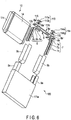
- FIG. 4 is a schematic exploded perspective view of an example of the electrode group according to the second embodiment.
- An electrode group 10 illustrated in FIG. 4 includes a positive electrode 11 and a negative electrode 12.
- the positive electrode 11 includes a belt-shaped positive electrode current collector 11a, and positive electrode layers 11b (one of which is not illustrated) provided on both surfaces of the positive electrode current collector.
- the positive electrode current collector 11a includes a portion 11c which does not support the positive electrode layer 11b.
- the portion 11c functions as a positive electrode tab of the electrode group 10.
- the negative electrode 12 includes a belt-shaped negative electrode current collector 12a.
- the negative electrode 12 further includes a negative electrode layer (not illustrated).
- the negative electrode layer is provided on both surfaces of the negative electrode current collector 12a.
- the negative electrode current collector 12a includes a portion 12c which does not support the negative electrode layer.
- the portion 12c functions as a negative electrode tab of the electrode group 10.
- the negative electrode 12 further includes an organic fiber-containing layer 13.
- the organic fiber-containing layer 13 is provided on the negative electrode layer.
- the organic fiber-containing layer 13 is also provided on the edge surface of the negative electrode layer.
- the positive electrode 11 and the negative electrode 12 are stacked to form a stack in a state in which the organic fiber-containing layer is sandwiched between the positive electrode layer 11b and the negative electrode layer.
- the positive electrode tab 11c and the negative electrode tab 12c protrude from the stack in opposite directions to each other.
- the stack including the positive electrode 11 and the negative electrode 12 is wound in a flat shape as illustrated in FIG. 4 to form the electrode group 10.
- the electrode group according to the second embodiment includes the electrode according to the first embodiment.
- the electrode group can achieve a nonaqueous electrolyte battery exhibiting high energy density and excellent input-and-output characteristics.
- a nonaqueous electrolyte battery includes the electrode group according to the second embodiment and a nonaqueous electrolyte impregnated into the electrode group.
- the nonaqueous electrolyte battery according to the third embodiment can further include a container member which accommodates the electrode group and the nonaqueous electrolyte.
- the nonaqueous electrolyte battery according to the third embodiment can further include a positive electrode terminal electrically connected to the positive electrode of the electrode group, and a negative electrode terminal electrically connected to the negative electrode of the electrode group.
- Each of the positive electrode terminal and the negative electrode terminal can be attached to the container member, for example, with an insulating member interposed therebetween.
- the container member may be either the positive electrode terminal or the negative electrode terminal.
- the nonaqueous electrolyte, the container member, the positive electrode terminal, the negative electrode terminal, and the insulating member which can be used in the nonaqueous electrolyte battery according to the third embodiment are explained.
- nonaqueous electrolyte it is possible to use a product prepared by dissolving an electrolyte (for example, a lithium salt) in a nonaqueous solvent.
- an electrolyte for example, a lithium salt
- the nonaqueous solvent may include, for example, ethylene carbonate (EC), propylene carbonate (PC), butylene carbonate (BC), dimethyl carbonate (DMC), diethyl carbonate (DEC), ethylmethyl carbonate (EMC), ⁇ -butyrolactone ( ⁇ -BL), sulpholane, acetonitrile, 1,2-dimethoxyethane, 1,3-dimethoxypropane, dimethyl ether, tetrahydrofuran (THF), 2-methyltetrahydrofuran, and the like.
- One nonaqueous solvent may be used alone or a mixture of two or more nonaqueous solvents may be used.
- the electrolyte may include, for example, lithium salts such as lithium perchlorate (LiClO 4 ), lithium hexafluorophosphate (LiPF 6 ), lithium tetrafluoroborate (LiBF 4 ), lithium hexafluoroarsenate (LiAsF 6 ), and lithium trifluoromethanesulfonate (LiCF 3 SO 3 ).
- lithium salts such as lithium perchlorate (LiClO 4 ), lithium hexafluorophosphate (LiPF 6 ), lithium tetrafluoroborate (LiBF 4 ), lithium hexafluoroarsenate (LiAsF 6 ), and lithium trifluoromethanesulfonate (LiCF 3 SO 3 ).
- LiCF 3 SO 3 lithium trifluoromethanesulfonate
- the concentration of the electrolyte is too low, sufficient ion-conductivity may not be obtained.
- the amount of the electrolyte supplied to the nonaqueous solvent is too large, the electrolyte may not be completely dissolved in the nonaqueous solvent.
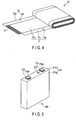
- the container member is a prismatic container having a bottom.
- the container member which can be included in the nonaqueous electrolyte battery according to the third embodiment is not particularly limited, and container members having various shapes can be used according to their intended use.
- a metal container member may be used, for example.
- aluminum, aluminum alloy, iron (Fe), iron plated with nickel (Ni), and stainless steel (SUS) may be used, for example.
- the container member may be made of a laminate film, for example.
- the laminate film it is possible to use a film formed of a metal layer and two resin layers sandwiching the metal layer therebetween.
- the positive electrode terminal and the negative electrode terminal from, for example, aluminum or aluminum alloy.
- connection of the positive electrode terminal to the positive electrode can be performed, for example, via a positive electrode lead.
- connection of the negative electrode terminal to the negative electrode can be performed, for example, via a negative electrode lead.
- the positive electrode lead and the negative electrode lead are formed, for example, from aluminum or aluminum alloy.
- a resin may be used as a material for the insulating member.
- a resin used for the insulating member any resin can be used so long as it is resistant to the liquid electrolyte.
- One of the resins described above may be used alone or a mixture of multiple kinds of
- FIG. 5 is a schematic perspective view of an example of a nonaqueous electrolyte battery according to a third embodiment.
- FIG. 6 is one exploded perspective view of the nonaqueous electrolyte battery illustrated in FIG. 5 .
- FIG. 7 is another exploded perspective view of the nonaqueous electrolyte battery illustrated in FIG. 5 .
- the nonaqueous electrolyte battery 100 of this example is a prismatic battery including a container member 111, an electrode group 10 accommodated in the container member 111, a liquid nonaqueous electrolyte (not illustrated) impregnated into the electrode group 10.
- the electrode group 10 is the flat wound-type electrode group 10 described with reference to FIG. 4 .
- the portion of the electrode group 10 other than a positive electrode tab 11c and a negative electrode tab 12c is covered with an insulating tape 14.
- the container member 111 includes a rectangular cylindrical metal container 111a with a bottom and having an opening, and a rectangular plate-shaped sealing member 111b provided on the opening of the container 111a.
- the sealing member 111b is joined to the opening of the container 111a by, for example, welding such as laser welding. Two through-holes (not illustrated) and an inlet port (not illustrated) are opened in the sealing member 111b.
- the nonaqueous electrolyte battery 100 of this example further includes a positive electrode lead 6 and a negative electrode lead 7.
- the positive electrode lead 6 includes a connection plate 6a with a through-hole 6b, and current-collection parts 6c bifurcating into two branches from the connection plate 6a and extending downward.
- the negative electrode lead 7 includes a connection plate 7a with a through-hole 7b, and current-collection parts 7c bifurcating into two branches from the connection plate 7a and extending downward.
- an insulator 8 is provided on a back surface of the sealing member 111b.
- the insulator 8 has a first concave portion 8a and a second concave portion 8b on a back surface thereof.
- a through-hole 8a' and a through-hole 8b' are opened in the first concave portion 8a and the second concave portion 8b, respectively, and the through-holes 8a' and 8b' communicate with the through-holes of the sealing member 111b, respectively.
- the connection plate 6a of the positive electrode lead 6 is provided in the first concave portion 8a, and the connection plate 7a of the negative electrode lead 7 is disposed in the second concave portion 8b.
- a through-hole 8c communicating with the inlet port of the sealing member 111b is opened in the insulator 8.
- the positive electrode lead 6 is joined to the positive electrode tab 11c of the electrode group 10 in a state where the outer surface of the positive electrode tab 11c is sandwiched between the bifurcated current-collection parts 6c of the positive electrode lead 6.
- the negative electrode lead 7 is joined to the negative electrode tab 12c in a state where the outer surface of the negative electrode tab 12c is sandwiched between the bifurcated current-collection parts 7c of the negative electrode lead 7.
- the nonaqueous electrolyte battery 100 of this example includes two insulating members 9a.
- One insulating member 9a covers a joined portion between the positive electrode lead 6 and the positive electrode tab 11c.
- the other insulating member 9a covers a joined portion between the negative electrode lead 7 and the negative electrode tab 12c.
- Each of the two insulating members 9a is fixed to the electrode group 10 by a twofold insulating tape 9b.
- the positive electrode terminal 113 includes a rectangular head part 113a, and a shaft 113b extending downward from the back surface of the head part 113a.
- the negative electrode terminal 114 includes a rectangular head part 114a, and a shaft 114b extending downward from the back surface of the head part 114a.
- Each of the positive electrode terminal 113 and the negative electrode terminal 114 is mounted on the upper surface of the sealing member 111b through insulating gaskets 115.
- the injection of the nonaqueous electrolyte can be performed by accommodating the electrode group 10 in the container 111a, joining the sealing member 111b to the opening of the container 111a, and then injecting the nonaqueous electrolyte through the inlet port opened in the sealing member 111b.
- a metallic sealing member 123 can be fitted into the inlet port and welded to seal the container member 111.
- Example 1 a nonaqueous electrolyte battery 100 having a structure similar to that of the nonaqueous electrolyte secondary battery 100 illustrated in FIGS. 5 to 7 which includes the wound-type electrode group 10 illustrated in FIG. 4 was produced.
- lithium-nickel-cobalt-manganese composite oxide LiNi 1/3 Co 1/3 Mn 1/3 O 2 and lithium-cobalt composite oxide LiCoO 2 were provided as a positive electrode active material. These were mixed so that LiNi 1/3 Co 1/3 Mn 1/3 O 2 and LiCoO 2 was 2 : 1 to obtain an active material mixture.
- the active material mixture, acetylene black as a conductive agent, graphite as a further conductive agent, and polyvinylidene fluoride as a binder were mixed at a mass ratio of 100 : 2 : 3 : 3.
- the mixture thus obtained was added to N-methyl-2-pyrrolidone as a solvent and kneaded and stirred with a planetary mixer to prepare a positive electrode slurry.
- a belt-shaped aluminum foil having a thickness of 20 ⁇ m was provided as the positive electrode current collector 11a.
- the positive electrode slurry previously prepared was coated on both surfaces of the aluminum foil 11a by a coating apparatus so that a coating amount per unit area was 70 g/m 2 .
- a portion 11c which was not coated with the positive electrode slurry was left along a long side of the aluminum foil 11a.
- the coated film thus obtained was dried. Subsequently, the dried coated film and the aluminum foil 11a were rolled by a roll press machine so that an electrode density (not including the aluminum foil) was 3.4 g/cm 3 .
- the positive electrode 11, including the positive electrode current collector 11a with the positive electrode tab 11c and the positive electrode layer 11b provided on the surface of the positive electrode current collector 11a was obtained.
- lithium titanate Li 4 Ti 5 O 12 was provided as a negative electrode active material.
- the active material, graphite as a conductive agent, and polyvinylidene fluoride as a binder were mixed at a mass ratio of 100 : 15 : 4.
- the mixture thus obtained was added to N-methyl-2-pyrrolidone as a solvent and kneaded and stirred with a planetary mixer to prepare a negative electrode slurry.
- a belt-shaped aluminum foil having a thickness of 20 ⁇ m was provided as the negative electrode current collector 12a.
- the negative electrode slurry previously prepared was coated on both surfaces of the aluminum foil 12a by a coating apparatus so that a coating amount per unit area was 65 g/m 2 .
- a portion 12c which was not coated with the negative electrode slurry was left along a long side of the aluminum foil.
- Polyvinylidene fluoride PVdF was used as an organic material.
- the PVdF was dissolved in N-methylpyrrolidone NMP serving as a solvent at a concentration of 20% by mass to prepare a material solution.
- the material solution was supplied from a spinning nozzle to the surface of the negative electrode 12 previously prepared at a supply rate of 6 mL/h by using a metering pump.
- fibers were supplied to the surface of the negative electrode layer including the end portion and a portion of the negative electrode tab 12c.
- the organic fiber-containing layer 13 including the PVdF fibers having a weight per unit area of 4 g/m 2 was formed by an electrospinning method.
- the organic fiber-containing layer 13 was roll-pressed so that the porosity thereof became 60%.
- a pressing pressure was 20 kN/m.
- the press roll was not heated, and the roll press was performed under an environment of 25°C.
- the negative electrode 12 of Example 1 including the negative electrode layer and the organic fiber-containing layer 13 provided on the negative electrode layer was obtained.
- the negative electrode 12 including the organic fiber-containing layer 13 provided on the surface thereof and the previously prepared positive electrode 11 were stacked in this order to obtain a stack. Subsequently, the stack was transferred to a winding apparatus, and the entire stack was bent and wound into a spiral shape. The wound body thus obtained was pressed to obtain a flat wound type electrode group 10 having the structure illustrated in FIG. 4 .
- the press was performed at 25°C, at 50 kN, and for 120 seconds.
- an insulator 8 was provided on a back surface of an aluminum sealing member 111b.
- a head part 113a of a positive electrode terminal 113 was mounted on an upper surface of the sealing member 111b with an insulating gasket 115 interposed therebetween, and a shaft 113b of the positive electrode terminal 113 was inserted into one through-hole of the sealing member 111b and a through-hole 8a' of the insulator 8.
- the positive electrode tab 11c of the wound-type electrode group 10 previously prepared was sandwiched between the bifurcated current-collector parts 6c of the positive electrode lead 6, and the positive electrode tab 11c and the positive electrode lead 6 were welded to each other in this state.
- the negative electrode tab 12c of the wound-type electrode group 10 was sandwiched between the bifurcated current collector parts 7c of the negative electrode lead 7, and the negative electrode tab 12c and the negative electrode lead 7 were welded in this state.
- the positive electrode terminal 113 was caulked and fixed to the connection plate 6a of the positive electrode lead 6.
- the negative electrode terminal 114 was caulked and fixed to the connection plate 7a of the negative electrode lead 7. In this way, the electrode group 10 and the sealing member 111b were integrated.
- an insulating member 9a was put on the positive electrode lead 6 and the positive electrode tab 11c so as to fix them.
- another insulating member 9a was put on the negative electrode lead 7 and the negative electrode tab 12c so as to fix them. Then, each of these insulating members 9a was fixed with insulating tape 9b.
- the unit of the insulating member 9a, the positive electrode lead 6 and the positive electrode tab 11c which were fixed as described above, and the unit of the insulating member 9a, the negative electrode lead 7 and the negative electrode tab 12c were inserted into the aluminum container 111a. Subsequently, the sealing member 111b was welded to the opening of the container 111a by a laser to produce a battery unit 100.
- the produced battery unit 100 had a rectangular parallelepiped shape with a width of 10 cm, a height of 10 cm, and a thickness of 2.5 cm.
- a nonaqueous solvent was prepared by mixing ethylene carbonate and dimethyl carbonate at a ratio of 1 : 1.
- lithium hexafluorophosphate LiPF 6 as an electrolyte was dissolved so as to have a concentration of 1 mol/L.
- a nonaqueous electrolyte was obtained.
- the prepared nonaqueous electrolyte was injected into the battery unit 100 from the inlet port of the sealing member 111b. After the injection, the sealing member 123 made of aluminum was fitted into the inlet port, and the periphery of the sealing member 123 was welded to the sealing member 111b. Thus, the nonaqueous electrolyte battery 100 of Example 1 was completed. 20 nonaqueous electrolyte batteries were prepared, and the 20 batteries could be charged and discharged without any abnormality. That is, the yield of Example 1 was 100%.
- the nonaqueous electrolyte battery 100 of Example 1 was adjusted to SOC 50%.
- AC resistance at 1 kHz in a 25°C atmosphere was measured, and was 1.25 m ⁇ . This resistance value was taken as a resistance value of the nonaqueous electrolyte battery of Example 1.
- a constant current charge was performed up to 2.8 V at 0.2 C and at 25°C, and thereafter, a charge was performed until a current value reached 0.01 C by a constant voltage charge. After that, the nonaqueous electrolyte battery 100 was stored in a 25°C atmosphere for one month.
- the nonaqueous electrolyte battery 100 after the storage was discharged at 0.33 C in a 25°C atmosphere until a voltage reached 1.3 V, and a discharge capacity was measured.
- the discharge capacity obtained here was taken as the capacity after the storage of the nonaqueous electrolyte battery 100 of Example 1.
- the discharge capacity after the storage of the nonaqueous electrolyte battery 100 of Example 1 was 21.41 Ah. That is, the self-discharge amount by the storage of the nonaqueous electrolyte battery 100 of Example 1 was 1.11 Ah.
- the nonaqueous electrolyte battery 100 of Example 1 was disassembled, and the electrode group 10 was taken out. At the time of disassembling, the electrolyte was kept separately. After that, the electrode group 10 was put in an Al laminate film bag together with the previously-kept liquid electrolyte at a temperature of 25°C and a dew point of -50°C or less, sealed at a gauge pressure of -70 kPa, and then stored for 5 days. Due to this, the organic fiber-containing layer 13 was impregnated with the liquid electrolyte.
- the electrode group 10 was sandwiched between resinous blocks in the thickness direction, pressurized at 101.3 kPa, and the thickness TL of the electrode group put in the bag was measured.
- the measured thickness TL of the electrode group 10 was 23.26 mm.
- the pressure was increased to 202.3 kPa, and the thickness TH of the electrode group 10 was measured in the same manner as described above.
- the measured thickness TH of the electrode group 10 was 23.00 mm.
- the number n of the organic fiber-containing layers in the thickness direction (direction of the short diameter) of the electrode group 10 was 280.
- the nonaqueous electrolyte battery 100 of Example 1 was disassembled, and the electrode group 10 was taken out. At the time of disassembling, the electrolyte was kept separately. Subsequently, the negative electrode 12 having the organic fiber-containing layer provided thereon was taken out from the electrode group 10, and a sample having a square planar shape of 5 cm square was cut out therefrom to prepare a sample of the negative electrode 12. After that, this sample was sandwiched between polyethylene protective films having a thickness of 12 ⁇ m and a square of 7 cm together with 1 g of the previously-kept liquid electrolyte. When sandwiched between the protective films, a part of the liquid electrolyte may come out from the peripheral portion of the protective film.
- the liquid electrolyte that has come out may be wiped off with a Kimtowel or the like.
- the sample was sealed in an Al laminate film bag under an environment of a temperature of 25°C and a dew point of -50°C or less, and was stored for 5 days.
- the organic fiber-containing layer 13 was impregnated with the liquid electrolyte.
- the sample was taken out from the Al laminate film bag, and the thickness was measured while sandwiching the sample between the protective films. As a result, the average t 1 of 10 points was 102.24 ⁇ m.
- the fiber diameter dW of the fibers included in the organic fiber-containing layer 13 in the wet state was measured with the confocal laser microscope VK-X100 manufactured by Keyence Corporation.
- the fiber diameter dW was 502 nm on an average of 50 points.
- the protective films were removed, the sample having the organic fiber-containing layer 13 was immersed in ethyl methyl carbonate for 10 minutes, the electrolyte was removed, and the solvent was dried under vacuum at 90°C. After that, the thickness of the sample was measured in the same manner, and the average t 2 of 10 points was 88.13 ⁇ m. At this time, the weight w 1 of the sample was measured. The weight w 1 of the sample was 0.9931 g. Further, the sample was sandwiched between the protective films in the same manner as described above, and the fiber diameter dD of the fibers included in the organic fiber-containing layer 13 in the dry state was measured with the confocal laser microscope VK-X100 manufactured by Keyence Corporation. The fiber diameter dD was 495 nm on an average of 50 points.
- the organic fiber-containing layer 13 was scrubbed off from both surfaces of the sample of the negative electrode 12, so as not to scrub off the negative electrode layer.
- the thickness of the sample was measured on 10 points in the same manner.
- the average t 3 of the thickness of the sample on 10 points was 73.89 ⁇ m.
- the weight w 2 of the sample was measured.
- the weight w 2 of the sample was 0.9634 g.
- the weight per unit area of the organic fiber-containing layer 13 in the dry state was calculated from the weight w 1 and the weight w 2 , and the average value on both surfaces thereof was 5.9 g/m 2 .
- the true density D1 was measured by using AccuPyc 1340-10cc manufactured by Shimadzu Corporation.
- the true density D 1 was 2.85 g/cm 3 .
- the porosity of the organic fiber-containing layer 13 in the dry state was calculated from the weight per unit area of the organic fiber-containing layer 13 and the true density D 1 of the organic fiber-containing layer 13 in the dry state.
- the porosity of the organic fiber-containing layer 13 in the dry state was 71%.
- the sample of the negative electrode 12, from which the organic fiber-containing layer 13 was scrubbed off was sandwiched between polyethylene protective films having a thickness of 12 ⁇ m and 7 cm square together with 1 g of the previously-kept liquid electrolyte in the same manner as described above.
- a part of the liquid electrolyte may come out from the peripheral portion of the protective film. In that case, the liquid electrolyte that has come out may be wiped off with a Kimtowel or the like.
- the sample was sealed in an Al laminate film bag under an environment at a temperature of 25°C and a dew point of -50°C or less and stored for 5 days, and the liquid electrolyte was impregnated into the negative electrode layer. After that, the sample was taken out from the Al laminate film bag, and the thickness was measured while sandwiching the sample between the protective films. As a result, the average t 4 of 10 points was 74.02 ⁇ m.
- the thickness tW in the wet state and the thickness tD in the dry state of the organic fiber-containing layer 13 of the nonaqueous electrolyte battery 100 of Example 1 were calculated by using the measured thicknesses t 1 to t 4 according to the procedure described above.
- the thickness tW was 14.11 ⁇ m
- the thickness tD in the dry state was 7.12. Calculation of the ratio tW / tD , the ratio dW / dD , and the ratio TL ⁇ TH / tW ⁇ n
- the ratio tW/tD of the organic fiber-containing layer 13 of the nonaqueous electrolyte battery 100 of Example 1 was 1.98.
- the ratio dW/dD of the average fiber diameter dW of the organic fibers included in the organic fiber-containing layer 13 in the wet state to the average fiber diameter dD of the organic fibers included in the organic fiber-containing layer 13 in the dry state was 1.01.
- the ratio (TL - TH) / (tW ⁇ n) of the electrode group 10 of the nonaqueous electrolyte battery 100 of Example 1 was 0.066.
- Example 2 a negative electrode 12 of Example 2 was produced by the same procedure as in Example 1, except that an organic fiber-containing layer 13 was roll-pressed so that the porosity thereof was 36%, and the negative electrode 12 was used to produce a nonaqueous electrolyte battery 100 of Example 2.
- the pressure of the roll press was 43 kN/m.
- Example 2 With respect to the nonaqueous electrolyte battery 100 of Example 2, various measurements were performed in the same procedure as in Example 1. As a result, the ratio tW/tD of Example 2 was 2.55. The ratio dW/dD of Example 2 was 0.98. In Example 2, the porosity of the organic fiber-containing layer 13 in the dry state was 40%. The ratio (TL - TH)/(tW ⁇ n) of Example 2 was 0.055. The yield of Example 2 was 100%. The self-discharge amount by storage of the nonaqueous electrolyte battery 100 of Example 2 was 1.29 Ah. The resistance value of the nonaqueous electrolyte battery 100 of Example 2 was 1.12 m ⁇ .
- Example 3 a negative electrode 12 of Example 3 was produced by the same procedure as in Example 1, except that an organic fiber-containing layer 13 was roll-pressed so that the porosity thereof was 78%, and the negative electrode 12 was used to prepare a nonaqueous electrolyte battery 100 of Example 3.
- the pressure of the roll press was 12 kN/m.
- Example 4 a negative electrode 12 of Example 4 was produced by the same procedure as in Example 1, except that polyimide was used as a fiber material, and the negative electrode 12 was used to produced a nonaqueous electrolyte battery 100 of Example 4.
- Example 4 With respect to the nonaqueous electrolyte battery 100 of Example 4, various measurements were performed in the same procedure as in Example 1. As a result, the ratio tW/tD of Example 4 was 1.17. The ratio dW/dD of Example 4 was 1.05. In Example 4, the porosity of the organic fiber-containing layer 13 in the dry state was 82%. The ratio (TL - TH)/(tW ⁇ n) of Example 4 was 0.038. The yield of Example 4 was 100%. The self-discharge amount by storage of the nonaqueous electrolyte battery 100 of Example 4 was 1.31 Ah. The resistance value of the nonaqueous electrolyte battery 100 of Example 4 was 1.13 m ⁇ .
- Example 5 the negative electrode 12 of Example 5 was produced by the same procedure as in Example 1, except that polyamide was used as a fiber material, and the negative electrode 12 was used to produce a nonaqueous electrolyte battery 100 of Example 5.
- Example 5 With respect to the nonaqueous electrolyte battery 100 of Example 5, various measurements were performed in the same procedure as in Example 1. As a result, the ratio tW/tD of Example 5 was 1.89. The ratio dW/dD of Example 5 was 1.02. In Example 5, the porosity of the organic fiber-containing layer 13 in the dry state was 62%. The ratio (TL - TH)/(tW ⁇ n) of Example 5 was 0.002. The yield of Example 5 was 100%. The self-discharge amount by storage of the nonaqueous electrolyte battery 100 of Example 5 was 1.14 Ah. The resistance value of the nonaqueous electrolyte battery 100 of Example 5 was 1.27 m ⁇ .
- Example 6 a negative electrode 12 of Example 6 was produced by the same procedure as in Example 1, except that polyamide-imide was used as a fiber material, and the negative electrode 12 was used to produce a nonaqueous electrolyte battery 100 of Example 6.
- Example 6 With respect to the nonaqueous electrolyte battery 100 of Example 6, various measurements were performed in the same procedure as in Example 1. As a result, the ratio tW/tD of Example 6 was 1.96. The ratio dW/dD of Example 6 was 0.98. In Example 6, the porosity of the organic fiber-containing layer 13 in the dry state was 60%. The ratio (TL - TH)/(tW ⁇ n) of Example 6 was 0.033. The yield of Example 6 was 100%. The self-discharge amount by storage of the nonaqueous electrolyte battery 100 of Example 6 was 1.13 Ah. The resistance value of the nonaqueous electrolyte battery 100 of Example 6 was 1.24 m ⁇ .
- Comparative Example 1 a negative electrode of Comparative Example 1 was produced by the same procedure as in Example 1, except that an organic fiber-containing layer 13 was roll-pressed while heating a press roll at 140°C, and the negative electrode was used to produce a nonaqueous electrolyte battery of Comparative Example 1.
- Comparative Example 3 a negative electrode of Comparative Example 3 was produced by the same procedure as in Example 1, except that an organic fiber-containing layer 13 was roll-pressed so that the porosity thereof was 91%, and the negative electrode was used to produce a nonaqueous electrolyte battery 100 of Comparative Example 3.
- the pressure of the roll press was 3 kN/m.
- the porosity of the organic fiber-containing layer 13 in the dry state was 91%.
- the organic fiber-containing layer 13 was peeled off from the negative electrode 12, and there were a plurality of places where the positive electrode 11 and the negative electrode 12 were in contact with each other.
- Comparative Example 4 a negative electrode of Comparative Example 4 was produced by the same procedure as in Example 1, except that an organic fiber-containing layer 13 was roll-pressed so that the porosity thereof was 28%, and the negative electrode was used to produce a nonaqueous electrolyte battery of Comparative Example 4.
- the pressure of the roll press was 60 kN/m.
- Comparative Example 5 a negative electrode 12 of Comparative Example 5 was produced by the same procedure as in Example 1, except that polyethylene oxide was used as a fiber material, and the negative electrode 12 was used to produce a nonaqueous electrolyte battery 100 of Comparative Example 5.
- the nonaqueous electrolyte batteries 100 of Examples 1 to 6 had a lower resistance than those of the nonaqueous electrolyte batteries of Comparative Examples 1, 2, 4, and 5. It is considered that the reason why the resistance of the nonaqueous electrolyte battery of Comparative Example 1 was higher than those of the nonaqueous electrolyte batteries 100 of Examples 1 to 6 was that, since the organic fiber-containing layer 13 was subjected to a hot roll press, the organic fiber-containing layer 13 was not increased by the impregnation with the liquid electrolyte.
- the nonaqueous electrolyte battery of Comparative Example 4 it is considered that the diffusion of Li ions was inhibited and thus the resistance was high. It is considered that the resistance of the nonaqueous electrolyte battery of Comparative Example 5 was high because the ratio dW/dD was greater than 1.05, so that the fiber diameter of the organic fiber included in the organic fiber-containing layer 13 became too large by the impregnation with the liquid electrolyte, and the organic fiber-containing layer 13 could not exhibit a high porosity even in the wet state.
- Example 7 With respect to the nonaqueous electrolyte battery 100 of Example 7, various measurements were performed in the same procedure as in Example 1. As a result, the ratio tW/tD of Example 7 was 2.36. The ratio dW/dD of Example 7 was 0.99. In Example 7, the porosity of the organic fiber-containing layer 13 in the dry state was 81%. The ratio (TL - TH)/(tW ⁇ n) of Example 7 was 0.086. The yield of Example 7 was 100%. The self-discharge amount by storage of the nonaqueous electrolyte battery 100 of Example 7 was 1.54 Ah. The resistance value of the nonaqueous electrolyte battery 100 of Example 7 was 1.16 m ⁇ .
- Example 8 a negative electrode of Example 8 was produced by the same procedure as in Example 1, except that an organic fiber-containing layer 13 was roll-pressed while heating a press roll at 60°C, and the negative electrode was used to produce a nonaqueous electrolyte battery of Example 8.
- Example 8 With respect to the nonaqueous electrolyte battery 100 of Example 8, various measurements were performed in the same procedure as in Example 1. As a result, the ratio tW/tD of Example 8 was 1.11. The ratio dW/dD of Example 8 was 0.96. In Example 8, the porosity of the organic fiber-containing layer 13 in the dry state was 79%. The ratio (TL - TH)/(tW ⁇ n) of Example 8 was 0.098. The yield of Example 8 was 100%. The self-discharge amount by storage of the nonaqueous electrolyte battery 100 of Example 8 was 1.39 Ah. The resistance value of the nonaqueous electrolyte battery 100 of Example 8 was 1.02 m ⁇ .
- Comparative Example 6 a negative electrode of Comparative Example 6 was prepared by the same procedure as in Example 1, except that a roll press was not performed after an organic fiber-containing layer 13 was formed, and the negative electrode was used to prepare a nonaqueous electrolyte battery 100 of Comparative Example 6.
- Comparative Example 6 a plurality of nonaqueous electrolyte batteries were produced as in Example 1. However, the yield of Comparative Example 6 was worse than that of Example 1.
- the organic fiber-containing layers 13 have thicknesses tW of 4.56 ⁇ m and 5.19 ⁇ m even in the wet state, respectively.
- the nonaqueous electrolyte batteries of Examples 7 and 8 could achieve excellent yields as described above even when thin organic fiber-containing layers were used.
- the use of the negative electrodes 12 of Examples 7 and 8 made it possible to realize the nonaqueous electrolyte battery 100 capable of exhibiting a high energy density and excellent input-and-output characteristics.
- the organic fibers 40 are deposited while entangling with each other.
- a frictional force is generated among the organic fibers 40, and, for example as illustrated in FIG. 8 , the organic fiber-containing layer 4 is in a compressed state.
- the roll press at a temperature lower than the softening point of the organic fiber material can prevent the organic fibers 40 from being fused together.
- the roll press is preferably performed at a temperature from room temperature to 60°C, and more preferably at room temperature.
- the room temperature is, for example, a temperature within a range of 20°C to 30°C.
- the organic fiber-containing layer when the organic fiber-containing layer is roll-pressed while being heated at a temperature higher than a softening point of the organic fiber material, the organic fibers are fused together. Even when the organic fiber-containing layer compressed as described above is impregnated with the liquid electrolyte, the entanglement of the organic fibers are not released or are hardly released. Also, when the organic fibers are bonded together by a binder, the organic fibers are bonded in a state of being entangled with each other, and thus, the entanglement of the organic fibers are not released or are hardly released even when impregnated with the liquid electrolyte. It is considered that this is the reason that the ratio tW/tD of Comparative Examples 1 and 2 was less than 1.1.
- the organic fiber-containing layer tends to be peeled off from the electrode layer when impregnated with the liquid electrolyte. This is considered to be because adhesion between the organic fiber and the electrode layer and adhesion among the organic fibers weaken due to the liquid electrolyte.
- the roll press of the organic fiber-containing layer performed in each of Examples is to compress the organic fiber-containing layer at a linear pressure of 10 kN/m or more.
- the press performed on the wound body obtained by winding the stack produced by using the negative electrode and the positive electrode is a press which applies a pressure on the surface. Therefore, the load applied to the organic fiber-containing layer by the press to the wound body is smaller than the load applied to the organic fiber-containing layer by the roll press.
- Comparative Example 3 the pressure during the roll press of the organic fiber-containing layer 13 was too low.
- Comparative Example 6 the wound body was produced without subjecting the organic fiber-containing layer formed on the negative electrode to roll-pressing, and the wound body is pressed. Therefore, in each of Comparative Example 3 and Comparative Example 6, the organic fiber-containing layer was not sufficiently pressed. As a result, it is considered that in the nonaqueous electrolyte batteries 100 of Comparative Example 3 and Comparative Example 6, a portion of the organic fiber-containing layer was peeled off from the negative electrode by the liquid electrolyte, and this portion led to an increase in the self-discharge.
- the electrode according to at least one embodiment and Example explained above includes the electrode layer and the organic fiber-containing layer.
- the organic fiber-containing layer is provided on the electrode layer.
- the organic fiber-containing layer includes the organic fiber.
- the organic fiber-containing layer has the ratio tW/tD within the range of 1.1 to 2.55, where tW is the thickness [ ⁇ m] of the organic fiber-containing layer in the wet state and tD is a thickness [ ⁇ m] of the organic fiber-containing layer in the dry state.
- the ratio dW/dD is within the range of 0.95 to 1.05, where dW is the average fiber diameter [nm] of the organic fiber included in the organic fiber-containing layer in the wet state, and dD is the average fiber diameter [nm] of the organic fiber included in the organic fiber-containing layer in the dry state. Due to these, the electrode can include the organic fiber-containing layer which is thin and has high porosity. As a result, the electrode can achieve a nonaqueous electrolyte battery exhibiting high energy density and excellent input-and-output characteristics.
Landscapes
- Chemical & Material Sciences (AREA)
- Chemical Kinetics & Catalysis (AREA)
- Electrochemistry (AREA)
- General Chemical & Material Sciences (AREA)
- Engineering & Computer Science (AREA)
- Manufacturing & Machinery (AREA)
- Materials Engineering (AREA)
- Life Sciences & Earth Sciences (AREA)
- Wood Science & Technology (AREA)
- Battery Electrode And Active Subsutance (AREA)
- Secondary Cells (AREA)
- Cell Separators (AREA)
Claims (14)
- Elektrode, umfassend:eine Elektrodenschicht; undeine organische Fasern enthaltende Schicht, die auf der Elektrodenschicht angeordnet ist und eine organische Faser umfasst,wobei die organische Fasern enthaltende Schicht ein Verhältnis tW/tD im Bereich von 1,1 bis 2,55 aufweist, wobei tW eine Dicke [µm] der organische Fasern enthaltenden Schicht in einem benetzten Zustand ist, in dem sie mit einem flüssigen Elektrolyt zu 500 mg oder mehr pro 1 cm3 imprägniert ist und tD eine Dicke [µm] der organische Fasern enthaltenden Schicht in einem trockenen Zustand ist, in dem eine imprägnierte Menge des flüssigen Elektrolyts pro 1 cm3 10 mg oder weniger beträgt, undein Verhältnis dW/dD im Bereich von 0,95 bis 1,05 liegt, wobei dW ein durchschnittlicher Faserdurchmesser [nm] der organischen Faser ist, die in der organische Fasern enthaltenden Schicht im benetzten Zustand enthalten ist, und dD ein durchschnittlicher Faserdurchmesser [nm] der organischen Faser ist, die in der organische Fasern enthaltenden Schicht im trockenen Zustand enthalten ist.
- Elektrode gemäß Anspruch 1, wobei die organische Fasern enthaltende Schicht im trockenen Zustand eine Porosität im Bereich von 40% bis 82% aufweist.
- Elektrode gemäß Anspruch 1 oder 2, wobei die organische Fasern enthaltende Schicht im trockenen Zustand ein Flächengewicht im Bereich von 0,5 g/m2 bis 4 g/m2 aufweist.
- Elektrode gemäß einem der Ansprüche 1 bis 3, wobei die organische Fasern enthaltende Schicht im trockenen Zustand ein Flächengewicht im Bereich von 1 g/m2 bis 4 g/m2 aufweist.
- Elektrode gemäß einem der Ansprüche 1 bis 4, wobei das Verhältnis tW/tD der Dicken 1,2 bis 2,3 beträgt.
- Elektrode gemäß einem der Ansprüche 1 bis 5, wobei das Verhältnis tW/tD der Dicken 1,3 bis 2,1 beträgt.
- Elektrode gemäß einem der Ansprüche 1 bis 6, wobei das Verhältnis dW/dD der durchschnittlichen Faserdurchmesser 0,96 bis 1,04 beträgt.
- Elektrode gemäß einem der Ansprüche 1 bis 7, wobei das Verhältnis dW/dD der durchschnittlichen Faserdurchmesser 0,98 bis 1,02 beträgt.
- Elektrode gemäß einem der Ansprüche 1 bis 8, wobei die organische Faser mindestens eine organische Verbindung umfasst, die aus der Gruppe ausgewählt ist, die aus Polyimid, Polyamid, Polyamidimid, Polyvinylidenfluorid, Polyolefin, Cellulose, Polyvinylalkohol und Polyacrylnitril besteht.
- Elektrodengruppe, umfassend:eine positive Elektrode, umfassend eine positive Elektrodenschicht; undeine negative Elektrode, umfassend eine negative Elektrodenschicht,wobei mindestens eine der positiven Elektrode und der negativen Elektrode die Elektrode gemäß einem der Ansprüche 1 bis 9 ist, unddie organische Fasern enthaltende Schicht zwischen der positiven Elektrodenschicht und der negativen Elektrodenschicht angeordnet ist.
- Elektrodengruppe gemäß Anspruch 10, wobei die Elektrodengruppe eine Elektrodengruppe vom flachen, gewundenen Typ ist, die einen Querschnitt mit einem langen Durchmesser und einem kurzen Durchmesser aufweist,
die Elektrodengruppe eine Dicke TL [mm] bei einem Druck von 101,3 kPa in einem Zustand, in dem sich die organische Fasern enthaltende Schicht im benetzten Zustand befindet, und eine Dicke TH [mm] bei einem Druck von 202,6 kPa in einem Zustand, in dem sich die organische Fasern enthaltende Schicht im benetzten Zustand befindet, aufweist und eine Anzahl der organischen Fasern enthaltenden Schichten in Richtung des kurzen Durchmessers der Elektrodengruppe n1 ist, und
die Dicke TH, die Dicke TL, die Dicke tW und die Anzahl n1 der organische Fasern enthaltenden Schichten die folgende Formel erfüllen:
- Elektrodengruppe gemäß Anspruch 10, wobei die Elektrodengruppe eine Struktur aufweist, in der mehrere positive Elektroden und mehrere negative Elektroden abwechselnd gestapelt sind,
die Elektrodengruppe eine Dicke TL [mm] bei einem Druck von 101,3 kPa in einem Zustand, in dem sich die organische Fasern enthaltende Schicht im benetzten Zustand befindet, und eine Dicke TH [mm] bei einem Druck von 202,6 kPa in einem Zustand, in dem sich die organische Fasern enthaltende Schicht sich im benetzten Zustand befindet, aufweist und eine Anzahl der organischen Fasern enthaltenden Schichten in Stapelrichtung n2 ist,
die Dicke TH, die Dicke TL, die Dicke tW und die Anzahl n2 der organische Fasern enthaltenden Schichten die folgende Formel erfüllen:
- Elektrodengruppe gemäß einem der Ansprüche 10 bis 12, wobei die negative Elektrodenschicht ein Lithium-Titan-Kompositoxid umfasst.
- Batterie mit nichtwässrigem Elektrolyt, umfassend:die Elektrodengruppe gemäß einem der Ansprüche 10 bis 13; undeinen nichtwässrigen Elektrolyt, der in die Elektrodengruppe imprägniert ist.
Applications Claiming Priority (2)
| Application Number | Priority Date | Filing Date | Title |
|---|---|---|---|
| JP2015077993 | 2015-04-06 | ||
| PCT/JP2016/061274 WO2016163404A1 (ja) | 2015-04-06 | 2016-04-06 | 電極、電極群及び非水電解質電池 |
Publications (3)
| Publication Number | Publication Date |
|---|---|
| EP3282502A1 EP3282502A1 (de) | 2018-02-14 |
| EP3282502A4 EP3282502A4 (de) | 2018-10-24 |
| EP3282502B1 true EP3282502B1 (de) | 2019-10-30 |
Family
ID=57072581
Family Applications (1)
| Application Number | Title | Priority Date | Filing Date |
|---|---|---|---|
| EP16776570.0A Active EP3282502B1 (de) | 2015-04-06 | 2016-04-06 | Elektrode, elektrodengruppe und batterie mit wasserfreiem elektrolyt |
Country Status (5)
| Country | Link |
|---|---|
| US (1) | US10454085B2 (de) |
| EP (1) | EP3282502B1 (de) |
| JP (1) | JP6408137B2 (de) |
| CN (1) | CN107534129B (de) |
| WO (1) | WO2016163404A1 (de) |
Families Citing this family (7)
| Publication number | Priority date | Publication date | Assignee | Title |
|---|---|---|---|---|
| JP6924047B2 (ja) * | 2017-03-10 | 2021-08-25 | 株式会社東芝 | 二次電池 |
| WO2018179613A1 (ja) * | 2017-03-28 | 2018-10-04 | 株式会社 東芝 | 電極構造体および二次電池 |
| JP2019153434A (ja) * | 2018-03-01 | 2019-09-12 | 株式会社東芝 | 積層体及び二次電池 |
| JP6847893B2 (ja) * | 2018-07-02 | 2021-03-24 | 株式会社東芝 | 電極構造体および二次電池 |
| US11121408B2 (en) | 2019-03-14 | 2021-09-14 | Medtronic, Inc. | Lithium-ion battery |
| CN113224297A (zh) * | 2020-02-06 | 2021-08-06 | 宁德新能源科技有限公司 | 负极极片、应用所述负极极片的电池以及电子装置 |
| WO2023182509A1 (ja) * | 2022-03-25 | 2023-09-28 | パナソニックIpマネジメント株式会社 | 電解コンデンサ用セパレータの製造方法、電解コンデンサの製造方法、電解コンデンサ用セパレータ、および電解コンデンサ |
Family Cites Families (24)
| Publication number | Priority date | Publication date | Assignee | Title |
|---|---|---|---|---|
| JP3614984B2 (ja) | 1996-06-19 | 2005-01-26 | 株式会社東芝 | シート状極板の製造方法およびこれを用いた非水電解質電池 |
| US6727017B1 (en) * | 2001-04-06 | 2004-04-27 | Changs Ascending Enterprise Co., Ltd. | Methods of fabricating binding layers for a Li-ion polymer battery |
| DE10238944A1 (de) * | 2002-08-24 | 2004-03-04 | Creavis Gesellschaft Für Technologie Und Innovation Mbh | Separator zur Verwendung in Hochenergiebatterien sowie Verfahren zu dessen Herstellung |
| WO2007054707A1 (en) * | 2005-11-11 | 2007-05-18 | Freudenberg Nonwovens Lp | Electrode separator |
| JP5403857B2 (ja) * | 2006-05-18 | 2014-01-29 | 日立マクセル株式会社 | 電池用セパレータ、その製造方法およびリチウム二次電池 |
| US8865336B2 (en) * | 2006-12-20 | 2014-10-21 | Kuraray Co., Ltd. | Separator for alkaline battery, method for producing the same, and battery |
| WO2010123686A1 (en) * | 2009-04-23 | 2010-10-28 | Toray Tonen Specialty Separator Company | Polymeric film, methods for making such film, and the use of such film as battery separator film |
| JP2012033498A (ja) * | 2010-04-08 | 2012-02-16 | Hitachi Maxell Energy Ltd | 電気化学素子 |
| KR101117126B1 (ko) * | 2010-04-19 | 2012-02-24 | 한국과학기술연구원 | 금속산화물 초극세 섬유-기반 내열성 복합 분리막 및 이를 이용한 이차전지 |
| JP2012059486A (ja) * | 2010-09-08 | 2012-03-22 | Konica Minolta Holdings Inc | リチウムイオン二次電池及びリチウムイオン二次電池用多孔質絶縁層 |
| EP2688123B1 (de) * | 2012-07-16 | 2017-07-05 | Commissariat à l'Énergie Atomique et aux Énergies Alternatives | Verfahren zur Herstellung einer Li-Ion-Batterie mit einem fluorpolymeren Abscheider |
| CN104508860B (zh) * | 2012-07-24 | 2016-06-29 | 株式会社东芝 | 二次电池 |
| JP6096908B2 (ja) * | 2012-11-30 | 2017-03-15 | エルジー・ケム・リミテッド | 有機バインダー高分子化合物で被覆されている繊維から形成された不織布、その不織布を含む電気化学素子、及びその不織布の製造方法 |
| EP2935665A2 (de) * | 2012-12-18 | 2015-10-28 | SABIC Global Technologies B.V. | Batterieseparatoren mit hochtemperaturschmelzfestigkeit mittels spinnen |
| JP2014139903A (ja) * | 2013-01-21 | 2014-07-31 | Daicel Corp | 蓄電素子用積層体の製造方法及びリチウムイオン電池 |
| JP6219113B2 (ja) * | 2013-09-30 | 2017-10-25 | 株式会社東芝 | 二次電池 |
| US20160308231A1 (en) * | 2013-12-03 | 2016-10-20 | Nippon Valqua Industries, Ltd. | Composite film for electrochemical element |
| US10186716B2 (en) * | 2014-11-10 | 2019-01-22 | Lanxess Solutions Us Inc. | Non-aqueous flow cell comprising a polyurethane separator |
| US10333173B2 (en) * | 2014-11-14 | 2019-06-25 | Medtronic, Inc. | Composite separator and electrolyte for solid state batteries |
| US10177360B2 (en) * | 2014-11-21 | 2019-01-08 | Hollingsworth & Vose Company | Battery separators with controlled pore structure |
| US20170263908A1 (en) * | 2016-03-08 | 2017-09-14 | Giner, Inc. | Separator For Use in Electrochemical Cells and Method of Fabrication Thereof |
| US10490843B2 (en) * | 2017-04-10 | 2019-11-26 | Nano And Advanced Materials Institute Limited | Flexible battery with 180 degree operational bend radius |
| US10734673B2 (en) * | 2017-06-23 | 2020-08-04 | GM Global Technology Operations LLC | Ionically-conductive reinforced glass ceramic separators/solid electrolytes |
| JP6805102B2 (ja) * | 2017-09-19 | 2020-12-23 | 株式会社東芝 | 二次電池用電極構造体、二次電池、電池パック及び車両 |
-
2016
- 2016-04-06 JP JP2017511022A patent/JP6408137B2/ja active Active
- 2016-04-06 EP EP16776570.0A patent/EP3282502B1/de active Active
- 2016-04-06 WO PCT/JP2016/061274 patent/WO2016163404A1/ja active Application Filing
- 2016-04-06 CN CN201680020635.5A patent/CN107534129B/zh active Active
-
2017
- 2017-10-04 US US15/724,706 patent/US10454085B2/en active Active
Non-Patent Citations (1)
| Title |
|---|
| None * |
Also Published As
| Publication number | Publication date |
|---|---|
| WO2016163404A1 (ja) | 2016-10-13 |
| EP3282502A1 (de) | 2018-02-14 |
| JP6408137B2 (ja) | 2018-10-17 |
| CN107534129A (zh) | 2018-01-02 |
| CN107534129B (zh) | 2021-02-02 |
| JPWO2016163404A1 (ja) | 2018-01-25 |
| US10454085B2 (en) | 2019-10-22 |
| US20180034026A1 (en) | 2018-02-01 |
| EP3282502A4 (de) | 2018-10-24 |
Similar Documents
| Publication | Publication Date | Title |
|---|---|---|
| EP3282502B1 (de) | Elektrode, elektrodengruppe und batterie mit wasserfreiem elektrolyt | |
| EP2942828B1 (de) | Lithiumelektrode und lithiumsekundärbatterie damit | |
| EP3070767B1 (de) | Elektrode, nicht wässrige elektrolytbatterie und batteriepack | |
| JP5783425B2 (ja) | 非水電解質二次電池の製造方法 | |
| US9634311B2 (en) | Separator including coating layer and battery including the same | |
| EP2950370A1 (de) | Lithium sekundaerbatterie | |
| EP2980895B1 (de) | Nichtwässrige elektrolytbatterie und batteriepack | |
| EP3300144A1 (de) | Sekundärbatterien | |
| US20130143125A1 (en) | Lithium ion secondary battery | |
| US20160294006A1 (en) | Nonaqueous electrolyte secondary cell and method for producing same | |
| JPH103946A (ja) | 非水電解液系二次電池 | |
| KR102243458B1 (ko) | 비수 전해질 이차전지, 및, 비수 전해질 이차전지의 제조 방법 | |
| EP3694028A1 (de) | Elektrode, batterie mit wasserfreiem elektrolyt und batteriepack | |
| US20110111302A1 (en) | Electrode plate for nonaqueous electrolyte secondary battery, method for fabricating the same, and nonaqueous electrolyte secondary battery | |
| EP3322024A1 (de) | Batterie mit wasserfreiem elektrolyt und batteriepack | |
| JP7247353B2 (ja) | 電極、電池、及び電池パック | |
| US8980482B2 (en) | Nonaqueous electrolyte lithium ion secondary battery | |
| JP6250941B2 (ja) | 非水電解質二次電池 | |
| EP3113276A1 (de) | Gewalzter elektrodensatz und batterie mit wasserfreiem elektrolyt | |
| US20220328818A1 (en) | Non-aqueous electrolyte secondary battery and method for manufacturing same | |
| JP2001102051A (ja) | 電極及びリチウム二次電池 | |
| US10741826B2 (en) | Method for manufacturing electrode plate and method for manufacturing secondary battery | |
| JPH11260417A (ja) | 高分子電解質リチウム二次電池 | |
| US20220293937A1 (en) | Positive electrode and non-aqueous electrolyte secondary battery including the positive electrode | |
| JP2012174414A (ja) | 非水電解質電池及びその製造方法 |
Legal Events
| Date | Code | Title | Description |
|---|---|---|---|
| STAA | Information on the status of an ep patent application or granted ep patent |
Free format text: STATUS: THE INTERNATIONAL PUBLICATION HAS BEEN MADE |
|
| PUAI | Public reference made under article 153(3) epc to a published international application that has entered the european phase |
Free format text: ORIGINAL CODE: 0009012 |
|
| STAA | Information on the status of an ep patent application or granted ep patent |
Free format text: STATUS: REQUEST FOR EXAMINATION WAS MADE |
|
| 17P | Request for examination filed |
Effective date: 20171009 |
|
| AK | Designated contracting states |
Kind code of ref document: A1 Designated state(s): AL AT BE BG CH CY CZ DE DK EE ES FI FR GB GR HR HU IE IS IT LI LT LU LV MC MK MT NL NO PL PT RO RS SE SI SK SM TR |
|
| AX | Request for extension of the european patent |
Extension state: BA ME |
|
| DAV | Request for validation of the european patent (deleted) | ||
| DAX | Request for extension of the european patent (deleted) | ||
| A4 | Supplementary search report drawn up and despatched |
Effective date: 20180920 |
|
| RIC1 | Information provided on ipc code assigned before grant |
Ipc: H01M 2/16 20060101ALI20180915BHEP Ipc: H01M 10/04 20060101ALI20180915BHEP Ipc: H01M 4/485 20100101ALI20180915BHEP Ipc: H01M 10/0587 20100101ALI20180915BHEP Ipc: H01M 4/131 20100101ALI20180915BHEP Ipc: H01M 4/02 20060101ALI20180915BHEP Ipc: H01M 4/13 20100101AFI20180915BHEP Ipc: H01M 10/0585 20100101ALI20180915BHEP |
|
| GRAP | Despatch of communication of intention to grant a patent |
Free format text: ORIGINAL CODE: EPIDOSNIGR1 |
|
| STAA | Information on the status of an ep patent application or granted ep patent |
Free format text: STATUS: GRANT OF PATENT IS INTENDED |
|
| INTG | Intention to grant announced |
Effective date: 20190605 |
|
| GRAS | Grant fee paid |
Free format text: ORIGINAL CODE: EPIDOSNIGR3 |
|
| GRAA | (expected) grant |
Free format text: ORIGINAL CODE: 0009210 |
|
| STAA | Information on the status of an ep patent application or granted ep patent |
Free format text: STATUS: THE PATENT HAS BEEN GRANTED |
|
| AK | Designated contracting states |
Kind code of ref document: B1 Designated state(s): AL AT BE BG CH CY CZ DE DK EE ES FI FR GB GR HR HU IE IS IT LI LT LU LV MC MK MT NL NO PL PT RO RS SE SI SK SM TR |
|
| REG | Reference to a national code |
Ref country code: GB Ref legal event code: FG4D |
|
| REG | Reference to a national code |
Ref country code: CH Ref legal event code: EP |
|
| REG | Reference to a national code |
Ref country code: AT Ref legal event code: REF Ref document number: 1197115 Country of ref document: AT Kind code of ref document: T Effective date: 20191115 |
|
| REG | Reference to a national code |
Ref country code: DE Ref legal event code: R096 Ref document number: 602016023411 Country of ref document: DE |
|
| REG | Reference to a national code |
Ref country code: IE Ref legal event code: FG4D |
|
| REG | Reference to a national code |
Ref country code: LT Ref legal event code: MG4D |
|
| PG25 | Lapsed in a contracting state [announced via postgrant information from national office to epo] |
Ref country code: LT Free format text: LAPSE BECAUSE OF FAILURE TO SUBMIT A TRANSLATION OF THE DESCRIPTION OR TO PAY THE FEE WITHIN THE PRESCRIBED TIME-LIMIT Effective date: 20191030 Ref country code: PL Free format text: LAPSE BECAUSE OF FAILURE TO SUBMIT A TRANSLATION OF THE DESCRIPTION OR TO PAY THE FEE WITHIN THE PRESCRIBED TIME-LIMIT Effective date: 20191030 Ref country code: NO Free format text: LAPSE BECAUSE OF FAILURE TO SUBMIT A TRANSLATION OF THE DESCRIPTION OR TO PAY THE FEE WITHIN THE PRESCRIBED TIME-LIMIT Effective date: 20200130 Ref country code: GR Free format text: LAPSE BECAUSE OF FAILURE TO SUBMIT A TRANSLATION OF THE DESCRIPTION OR TO PAY THE FEE WITHIN THE PRESCRIBED TIME-LIMIT Effective date: 20200131 Ref country code: FI Free format text: LAPSE BECAUSE OF FAILURE TO SUBMIT A TRANSLATION OF THE DESCRIPTION OR TO PAY THE FEE WITHIN THE PRESCRIBED TIME-LIMIT Effective date: 20191030 Ref country code: BG Free format text: LAPSE BECAUSE OF FAILURE TO SUBMIT A TRANSLATION OF THE DESCRIPTION OR TO PAY THE FEE WITHIN THE PRESCRIBED TIME-LIMIT Effective date: 20200130 Ref country code: LV Free format text: LAPSE BECAUSE OF FAILURE TO SUBMIT A TRANSLATION OF THE DESCRIPTION OR TO PAY THE FEE WITHIN THE PRESCRIBED TIME-LIMIT Effective date: 20191030 Ref country code: SE Free format text: LAPSE BECAUSE OF FAILURE TO SUBMIT A TRANSLATION OF THE DESCRIPTION OR TO PAY THE FEE WITHIN THE PRESCRIBED TIME-LIMIT Effective date: 20191030 Ref country code: PT Free format text: LAPSE BECAUSE OF FAILURE TO SUBMIT A TRANSLATION OF THE DESCRIPTION OR TO PAY THE FEE WITHIN THE PRESCRIBED TIME-LIMIT Effective date: 20200302 Ref country code: NL Free format text: LAPSE BECAUSE OF FAILURE TO SUBMIT A TRANSLATION OF THE DESCRIPTION OR TO PAY THE FEE WITHIN THE PRESCRIBED TIME-LIMIT Effective date: 20191030 |
|
| REG | Reference to a national code |
Ref country code: NL Ref legal event code: MP Effective date: 20191030 |
|
| PG25 | Lapsed in a contracting state [announced via postgrant information from national office to epo] |
Ref country code: IS Free format text: LAPSE BECAUSE OF FAILURE TO SUBMIT A TRANSLATION OF THE DESCRIPTION OR TO PAY THE FEE WITHIN THE PRESCRIBED TIME-LIMIT Effective date: 20200229 Ref country code: HR Free format text: LAPSE BECAUSE OF FAILURE TO SUBMIT A TRANSLATION OF THE DESCRIPTION OR TO PAY THE FEE WITHIN THE PRESCRIBED TIME-LIMIT Effective date: 20191030 Ref country code: RS Free format text: LAPSE BECAUSE OF FAILURE TO SUBMIT A TRANSLATION OF THE DESCRIPTION OR TO PAY THE FEE WITHIN THE PRESCRIBED TIME-LIMIT Effective date: 20191030 |
|
| PG25 | Lapsed in a contracting state [announced via postgrant information from national office to epo] |
Ref country code: AL Free format text: LAPSE BECAUSE OF FAILURE TO SUBMIT A TRANSLATION OF THE DESCRIPTION OR TO PAY THE FEE WITHIN THE PRESCRIBED TIME-LIMIT Effective date: 20191030 |
|
| PG25 | Lapsed in a contracting state [announced via postgrant information from national office to epo] |
Ref country code: CZ Free format text: LAPSE BECAUSE OF FAILURE TO SUBMIT A TRANSLATION OF THE DESCRIPTION OR TO PAY THE FEE WITHIN THE PRESCRIBED TIME-LIMIT Effective date: 20191030 Ref country code: ES Free format text: LAPSE BECAUSE OF FAILURE TO SUBMIT A TRANSLATION OF THE DESCRIPTION OR TO PAY THE FEE WITHIN THE PRESCRIBED TIME-LIMIT Effective date: 20191030 Ref country code: RO Free format text: LAPSE BECAUSE OF FAILURE TO SUBMIT A TRANSLATION OF THE DESCRIPTION OR TO PAY THE FEE WITHIN THE PRESCRIBED TIME-LIMIT Effective date: 20191030 Ref country code: EE Free format text: LAPSE BECAUSE OF FAILURE TO SUBMIT A TRANSLATION OF THE DESCRIPTION OR TO PAY THE FEE WITHIN THE PRESCRIBED TIME-LIMIT Effective date: 20191030 Ref country code: DK Free format text: LAPSE BECAUSE OF FAILURE TO SUBMIT A TRANSLATION OF THE DESCRIPTION OR TO PAY THE FEE WITHIN THE PRESCRIBED TIME-LIMIT Effective date: 20191030 |
|
| REG | Reference to a national code |
Ref country code: DE Ref legal event code: R097 Ref document number: 602016023411 Country of ref document: DE |
|
| REG | Reference to a national code |
Ref country code: AT Ref legal event code: MK05 Ref document number: 1197115 Country of ref document: AT Kind code of ref document: T Effective date: 20191030 |
|
| PG25 | Lapsed in a contracting state [announced via postgrant information from national office to epo] |
Ref country code: SM Free format text: LAPSE BECAUSE OF FAILURE TO SUBMIT A TRANSLATION OF THE DESCRIPTION OR TO PAY THE FEE WITHIN THE PRESCRIBED TIME-LIMIT Effective date: 20191030 Ref country code: IT Free format text: LAPSE BECAUSE OF FAILURE TO SUBMIT A TRANSLATION OF THE DESCRIPTION OR TO PAY THE FEE WITHIN THE PRESCRIBED TIME-LIMIT Effective date: 20191030 Ref country code: SK Free format text: LAPSE BECAUSE OF FAILURE TO SUBMIT A TRANSLATION OF THE DESCRIPTION OR TO PAY THE FEE WITHIN THE PRESCRIBED TIME-LIMIT Effective date: 20191030 |
|
| PLBE | No opposition filed within time limit |
Free format text: ORIGINAL CODE: 0009261 |
|
| STAA | Information on the status of an ep patent application or granted ep patent |
Free format text: STATUS: NO OPPOSITION FILED WITHIN TIME LIMIT |
|
| 26N | No opposition filed |
Effective date: 20200731 |
|
| PG25 | Lapsed in a contracting state [announced via postgrant information from national office to epo] |
Ref country code: AT Free format text: LAPSE BECAUSE OF FAILURE TO SUBMIT A TRANSLATION OF THE DESCRIPTION OR TO PAY THE FEE WITHIN THE PRESCRIBED TIME-LIMIT Effective date: 20191030 Ref country code: MC Free format text: LAPSE BECAUSE OF FAILURE TO SUBMIT A TRANSLATION OF THE DESCRIPTION OR TO PAY THE FEE WITHIN THE PRESCRIBED TIME-LIMIT Effective date: 20191030 Ref country code: SI Free format text: LAPSE BECAUSE OF FAILURE TO SUBMIT A TRANSLATION OF THE DESCRIPTION OR TO PAY THE FEE WITHIN THE PRESCRIBED TIME-LIMIT Effective date: 20191030 |
|
| REG | Reference to a national code |
Ref country code: CH Ref legal event code: PL |
|
| PG25 | Lapsed in a contracting state [announced via postgrant information from national office to epo] |
Ref country code: LU Free format text: LAPSE BECAUSE OF NON-PAYMENT OF DUE FEES Effective date: 20200406 Ref country code: CH Free format text: LAPSE BECAUSE OF NON-PAYMENT OF DUE FEES Effective date: 20200430 Ref country code: LI Free format text: LAPSE BECAUSE OF NON-PAYMENT OF DUE FEES Effective date: 20200430 |
|
| REG | Reference to a national code |
Ref country code: BE Ref legal event code: MM Effective date: 20200430 |
|
| PG25 | Lapsed in a contracting state [announced via postgrant information from national office to epo] |
Ref country code: BE Free format text: LAPSE BECAUSE OF NON-PAYMENT OF DUE FEES Effective date: 20200430 |
|
| PG25 | Lapsed in a contracting state [announced via postgrant information from national office to epo] |
Ref country code: IE Free format text: LAPSE BECAUSE OF NON-PAYMENT OF DUE FEES Effective date: 20200406 |
|
| PG25 | Lapsed in a contracting state [announced via postgrant information from national office to epo] |
Ref country code: TR Free format text: LAPSE BECAUSE OF FAILURE TO SUBMIT A TRANSLATION OF THE DESCRIPTION OR TO PAY THE FEE WITHIN THE PRESCRIBED TIME-LIMIT Effective date: 20191030 Ref country code: MT Free format text: LAPSE BECAUSE OF FAILURE TO SUBMIT A TRANSLATION OF THE DESCRIPTION OR TO PAY THE FEE WITHIN THE PRESCRIBED TIME-LIMIT Effective date: 20191030 Ref country code: CY Free format text: LAPSE BECAUSE OF FAILURE TO SUBMIT A TRANSLATION OF THE DESCRIPTION OR TO PAY THE FEE WITHIN THE PRESCRIBED TIME-LIMIT Effective date: 20191030 |
|
| PG25 | Lapsed in a contracting state [announced via postgrant information from national office to epo] |
Ref country code: MK Free format text: LAPSE BECAUSE OF FAILURE TO SUBMIT A TRANSLATION OF THE DESCRIPTION OR TO PAY THE FEE WITHIN THE PRESCRIBED TIME-LIMIT Effective date: 20191030 |
|
| PGFP | Annual fee paid to national office [announced via postgrant information from national office to epo] |
Ref country code: FR Payment date: 20230221 Year of fee payment: 8 |
|
| PGFP | Annual fee paid to national office [announced via postgrant information from national office to epo] |
Ref country code: DE Payment date: 20230222 Year of fee payment: 8 |
|
| PGFP | Annual fee paid to national office [announced via postgrant information from national office to epo] |
Ref country code: GB Payment date: 20240222 Year of fee payment: 9 |