EP4477902A1 - Rotor main bearing of a nacelle for a wind turbine - Google Patents
Rotor main bearing of a nacelle for a wind turbine Download PDFInfo
- Publication number
- EP4477902A1 EP4477902A1 EP24194950.2A EP24194950A EP4477902A1 EP 4477902 A1 EP4477902 A1 EP 4477902A1 EP 24194950 A EP24194950 A EP 24194950A EP 4477902 A1 EP4477902 A1 EP 4477902A1
- Authority
- EP
- European Patent Office
- Prior art keywords
- ring element
- nacelle
- bearing
- inner ring
- outer ring
- Prior art date
- Legal status (The legal status is an assumption and is not a legal conclusion. Google has not performed a legal analysis and makes no representation as to the accuracy of the status listed.)
- Withdrawn
Links
Images
Classifications
-
- F—MECHANICAL ENGINEERING; LIGHTING; HEATING; WEAPONS; BLASTING
- F16—ENGINEERING ELEMENTS AND UNITS; GENERAL MEASURES FOR PRODUCING AND MAINTAINING EFFECTIVE FUNCTIONING OF MACHINES OR INSTALLATIONS; THERMAL INSULATION IN GENERAL
- F16C—SHAFTS; FLEXIBLE SHAFTS; ELEMENTS OR CRANKSHAFT MECHANISMS; ROTARY BODIES OTHER THAN GEARING ELEMENTS; BEARINGS
- F16C17/00—Sliding-contact bearings for exclusively rotary movement
- F16C17/10—Sliding-contact bearings for exclusively rotary movement for both radial and axial load
- F16C17/102—Sliding-contact bearings for exclusively rotary movement for both radial and axial load with grooves in the bearing surface to generate hydrodynamic pressure
- F16C17/105—Sliding-contact bearings for exclusively rotary movement for both radial and axial load with grooves in the bearing surface to generate hydrodynamic pressure with at least one bearing surface providing angular contact, e.g. conical or spherical bearing surfaces
-
- F—MECHANICAL ENGINEERING; LIGHTING; HEATING; WEAPONS; BLASTING
- F03—MACHINES OR ENGINES FOR LIQUIDS; WIND, SPRING, OR WEIGHT MOTORS; PRODUCING MECHANICAL POWER OR A REACTIVE PROPULSIVE THRUST, NOT OTHERWISE PROVIDED FOR
- F03D—WIND MOTORS
- F03D80/00—Details, components or accessories not provided for in groups F03D1/00 - F03D17/00
- F03D80/70—Bearing or lubricating arrangements
-
- F—MECHANICAL ENGINEERING; LIGHTING; HEATING; WEAPONS; BLASTING
- F16—ENGINEERING ELEMENTS AND UNITS; GENERAL MEASURES FOR PRODUCING AND MAINTAINING EFFECTIVE FUNCTIONING OF MACHINES OR INSTALLATIONS; THERMAL INSULATION IN GENERAL
- F16C—SHAFTS; FLEXIBLE SHAFTS; ELEMENTS OR CRANKSHAFT MECHANISMS; ROTARY BODIES OTHER THAN GEARING ELEMENTS; BEARINGS
- F16C33/00—Parts of bearings; Special methods for making bearings or parts thereof
- F16C33/02—Parts of sliding-contact bearings
- F16C33/04—Brasses; Bushes; Linings
- F16C33/06—Sliding surface mainly made of metal
- F16C33/08—Attachment of brasses, bushes or linings to the bearing housing
-
- F—MECHANICAL ENGINEERING; LIGHTING; HEATING; WEAPONS; BLASTING
- F16—ENGINEERING ELEMENTS AND UNITS; GENERAL MEASURES FOR PRODUCING AND MAINTAINING EFFECTIVE FUNCTIONING OF MACHINES OR INSTALLATIONS; THERMAL INSULATION IN GENERAL
- F16C—SHAFTS; FLEXIBLE SHAFTS; ELEMENTS OR CRANKSHAFT MECHANISMS; ROTARY BODIES OTHER THAN GEARING ELEMENTS; BEARINGS
- F16C33/00—Parts of bearings; Special methods for making bearings or parts thereof
- F16C33/02—Parts of sliding-contact bearings
- F16C33/04—Brasses; Bushes; Linings
- F16C33/20—Sliding surface consisting mainly of plastics
- F16C33/208—Methods of manufacture, e.g. shaping, applying coatings
-
- F—MECHANICAL ENGINEERING; LIGHTING; HEATING; WEAPONS; BLASTING
- F05—INDEXING SCHEMES RELATING TO ENGINES OR PUMPS IN VARIOUS SUBCLASSES OF CLASSES F01-F04
- F05B—INDEXING SCHEME RELATING TO WIND, SPRING, WEIGHT, INERTIA OR LIKE MOTORS, TO MACHINES OR ENGINES FOR LIQUIDS COVERED BY SUBCLASSES F03B, F03D AND F03G
- F05B2230/00—Manufacture
- F05B2230/60—Assembly methods
-
- F—MECHANICAL ENGINEERING; LIGHTING; HEATING; WEAPONS; BLASTING
- F05—INDEXING SCHEMES RELATING TO ENGINES OR PUMPS IN VARIOUS SUBCLASSES OF CLASSES F01-F04
- F05B—INDEXING SCHEME RELATING TO WIND, SPRING, WEIGHT, INERTIA OR LIKE MOTORS, TO MACHINES OR ENGINES FOR LIQUIDS COVERED BY SUBCLASSES F03B, F03D AND F03G
- F05B2240/00—Components
- F05B2240/50—Bearings
-
- F—MECHANICAL ENGINEERING; LIGHTING; HEATING; WEAPONS; BLASTING
- F16—ENGINEERING ELEMENTS AND UNITS; GENERAL MEASURES FOR PRODUCING AND MAINTAINING EFFECTIVE FUNCTIONING OF MACHINES OR INSTALLATIONS; THERMAL INSULATION IN GENERAL
- F16C—SHAFTS; FLEXIBLE SHAFTS; ELEMENTS OR CRANKSHAFT MECHANISMS; ROTARY BODIES OTHER THAN GEARING ELEMENTS; BEARINGS
- F16C2220/00—Shaping
- F16C2220/24—Shaping by built-up welding
-
- F—MECHANICAL ENGINEERING; LIGHTING; HEATING; WEAPONS; BLASTING
- F16—ENGINEERING ELEMENTS AND UNITS; GENERAL MEASURES FOR PRODUCING AND MAINTAINING EFFECTIVE FUNCTIONING OF MACHINES OR INSTALLATIONS; THERMAL INSULATION IN GENERAL
- F16C—SHAFTS; FLEXIBLE SHAFTS; ELEMENTS OR CRANKSHAFT MECHANISMS; ROTARY BODIES OTHER THAN GEARING ELEMENTS; BEARINGS
- F16C2223/00—Surface treatments; Hardening; Coating
- F16C2223/30—Coating surfaces
- F16C2223/46—Coating surfaces by welding, e.g. by using a laser to build a layer
-
- F—MECHANICAL ENGINEERING; LIGHTING; HEATING; WEAPONS; BLASTING
- F16—ENGINEERING ELEMENTS AND UNITS; GENERAL MEASURES FOR PRODUCING AND MAINTAINING EFFECTIVE FUNCTIONING OF MACHINES OR INSTALLATIONS; THERMAL INSULATION IN GENERAL
- F16C—SHAFTS; FLEXIBLE SHAFTS; ELEMENTS OR CRANKSHAFT MECHANISMS; ROTARY BODIES OTHER THAN GEARING ELEMENTS; BEARINGS
- F16C2240/00—Specified values or numerical ranges of parameters; Relations between them
- F16C2240/40—Linear dimensions, e.g. length, radius, thickness, gap
- F16C2240/54—Surface roughness
-
- F—MECHANICAL ENGINEERING; LIGHTING; HEATING; WEAPONS; BLASTING
- F16—ENGINEERING ELEMENTS AND UNITS; GENERAL MEASURES FOR PRODUCING AND MAINTAINING EFFECTIVE FUNCTIONING OF MACHINES OR INSTALLATIONS; THERMAL INSULATION IN GENERAL
- F16C—SHAFTS; FLEXIBLE SHAFTS; ELEMENTS OR CRANKSHAFT MECHANISMS; ROTARY BODIES OTHER THAN GEARING ELEMENTS; BEARINGS
- F16C2240/00—Specified values or numerical ranges of parameters; Relations between them
- F16C2240/40—Linear dimensions, e.g. length, radius, thickness, gap
- F16C2240/60—Thickness, e.g. thickness of coatings
-
- F—MECHANICAL ENGINEERING; LIGHTING; HEATING; WEAPONS; BLASTING
- F16—ENGINEERING ELEMENTS AND UNITS; GENERAL MEASURES FOR PRODUCING AND MAINTAINING EFFECTIVE FUNCTIONING OF MACHINES OR INSTALLATIONS; THERMAL INSULATION IN GENERAL
- F16C—SHAFTS; FLEXIBLE SHAFTS; ELEMENTS OR CRANKSHAFT MECHANISMS; ROTARY BODIES OTHER THAN GEARING ELEMENTS; BEARINGS
- F16C2360/00—Engines or pumps
- F16C2360/31—Wind motors
-
- Y—GENERAL TAGGING OF NEW TECHNOLOGICAL DEVELOPMENTS; GENERAL TAGGING OF CROSS-SECTIONAL TECHNOLOGIES SPANNING OVER SEVERAL SECTIONS OF THE IPC; TECHNICAL SUBJECTS COVERED BY FORMER USPC CROSS-REFERENCE ART COLLECTIONS [XRACs] AND DIGESTS
- Y02—TECHNOLOGIES OR APPLICATIONS FOR MITIGATION OR ADAPTATION AGAINST CLIMATE CHANGE
- Y02E—REDUCTION OF GREENHOUSE GAS [GHG] EMISSIONS, RELATED TO ENERGY GENERATION, TRANSMISSION OR DISTRIBUTION
- Y02E10/00—Energy generation through renewable energy sources
- Y02E10/70—Wind energy
- Y02E10/72—Wind turbines with rotation axis in wind direction
Definitions
- the invention relates to a nacelle with a rotor bearing for a wind turbine.
- the object of the present invention was to overcome the disadvantages of the prior art and to provide a nacelle for a wind turbine which has an improved rotor bearing. Furthermore, the object of the present invention was to provide a method for producing the nacelle for the wind turbine.
- the plain bearing element has a running surface.
- the running surface of the plain bearing element interacts with a surface of the inner ring element when the plain bearing element is inseparably connected to the outer ring element.
- the running surface of the plain bearing element interacts with a surface of the outer ring element when the plain bearing element is inseparably connected to the inner ring element.
- the nacelle according to the invention in particular the rotor bearing of the nacelle, has the surprising advantage that it has a simple structure and is less susceptible to errors and has a long service life.
- the inner ring element is designed as an integral part of a rotor shaft for receiving the rotor hub or as an integral part of the rotor hub itself. This further simplifies the structure of the nacelle and surprisingly increases reliability.
- the outer ring element is designed as an integral part of the nacelle housing or of a bearing block accommodated in the nacelle housing. This brings about a further simplification of the structure of the nacelle and a surprising increase in reliability.
- the nacelle housing is the entirety of the load-bearing nacelle components. This can also be, for example, a nacelle main frame. In particular, it can be provided that the outer ring element is formed in the nacelle main frame.
- the bearing block is designed to be radially divided.
- the bearing block can, for example, be divided into two bearing block halves. It is conceivable that a part of the plain bearing element is formed in both of the bearing block halves or is connected to them.
- the plain bearing element can be designed to be radially or axially divided together with the inner ring element or outer ring element receiving the plain bearing element.
- the plain bearing element is integrally connected to the inner ring element or that the plain bearing element is integrally connected to the outer ring element.
- such an integral connection of the plain bearing element with the ring element brings with it a surprising increase in reliability. Additional improvements in reliability can be achieved, particularly in conjunction with the measure whereby the inner ring element is designed as an integral component of a rotor shaft for receiving the rotor hub or as an integral component of the rotor hub itself.
- the plain bearing element can be designed as a coating that is applied directly to the inner ring element or the outer ring element.
- a coating applied directly to the ring element is particularly easy to produce and has a precise shape.
- the plain bearing element prefferably be designed for simultaneous radial and axial bearing of the rotor hub. This has the advantage that no separate bearing elements have to be designed for the radial bearing and the axial bearing of the rotor hub.
- the plain bearing element has different material properties in the area of the radial bearing than in the area of the axial bearing. This has the advantage that the plain bearing element can have sliding properties adapted to the respective different loads of the radial bearing and the axial bearing. In particular, it can be provided that the plain bearing element can have a higher strength and/or a higher wear resistance in the area of the radial bearing than in the area of the axial bearing.
- the plain bearing element has a sliding surface in the form of a spherical cap.
- the shape of a spherical cap is easy to manufacture and also has the advantage that efficient radial bearing and simultaneous axial bearing of the rotor hub can be achieved.
- the inner ring element and/or the outer ring element is split in the axial direction. This has the advantage that the rotor bearing can be easily assembled.
- the ring element on which the plain bearing element is not arranged is split in the axial direction. This measure can ensure that the rotor bearing has a high level of functionality in use and a high level of durability, despite the possibility of simply assembling it.
- the method according to the invention for producing a nacelle, in particular the rotor bearing of the nacelle, has the surprising advantage that it is easy to carry out and is therefore less prone to errors in order to be able to produce a nacelle with a long service life.
- the plain bearing element is applied to the inner ring element or the outer ring element by coating.
- a coating applied directly to the ring element is particularly simple and precise to produce.
- the plain bearing element is applied to the inner ring element or the outer ring element by magnetic pulse welding using a magnetic force generator.
- the magnetic pulse welding process can be used to functionally integrate plain bearing elements with excellent sliding properties into the nacelles of wind turbines.
- the strength of the plain bearing element is smaller than the strength of the inner ring element and the outer ring element. This has the advantage that the material of the bearing body can be easily adapted to the material of the carrier body or can be pressed together with it.
- a surface structure is formed on the inner ring element or on the outer ring element and that in order to apply the plain bearing element to the inner ring element or to the outer ring element, the plain bearing element and the inner ring element or the outer ring element are pressed together, wherein the plain bearing element is plastically deformed at a connection surface to the inner ring element or to the outer ring element by the effect of the surface structure of the inner ring element or the outer ring element and forms a positive connection with the connection surface.
- This measure can ensure that a sufficiently strong connection can be achieved between the plain bearing element and the inner ring element or the outer ring element, so that the rotor bearing has a high long-term durability and is also easy to manufacture.
- the surface structure of the connecting surface has undercuts into which the plain bearing element material is pressed. This measure can achieve a positive connection between the inner ring element or the outer ring element and the plain bearing.
- the surface structuring is produced by means of a laser.
- the surface structuring can be produced using a 3D printing process.
- the surface structure has webs, wherein the webs are deformed when the bearing body and the carrier body are pressed together. This brings with it the surprising advantage that the connection between the bearing body and the carrier body can have increased strength.
- the webs are arranged substantially at right angles to the carrier body connection surface.
- Another advantageous embodiment is one in which the webs can be bent transversely to their longitudinal extension when the bearing body and the carrier body are pressed together. This surprisingly allows a good connection between the carrier body and the bearing body to be achieved.
- the webs in a web head to have a head cross-sectional width and for the webs at a web base to have a base cross-sectional width, wherein the head cross-sectional width is greater than the base cross-sectional width.
- the surface structuring of the carrier body connection surface is produced by means of a forming process, in particular by knurling.
- the required surface structure of the carrier body can be produced easily, in particular by means of such a rolling process.
- the surface structure of the connecting surface has cross knurling or left-right knurling.
- the process of cross knurling or left-right knurling or the surfaces produced thereby provide an improved Durability between the bearing body and the carrier body.
- Such knurling processes are standardized in DIN 8583-5, DIN 82, DIN 403.
- the following designation can be used for the knurls mentioned above according to the standard: RGE: left-right knurl, raised tips (fish skin); RGV: left-right knurl, recessed tips; RKE: cross knurl, raised tips; RKV: cross knurl, recessed tips.
- knurling When knurling, a distinction is made between non-cutting knurling and cutting knurling. Depending on the process, the profile is pressed in with knurling wheels or milled on a knurling machine. Special knurling milling tools can also be used on CNC lathes with driven tools to avoid having to change the tool to another machine. Since the machining forces are lower when milling, it is mainly used for thin workpieces or on machining centers.
- the surfaces produced by cross knurling or left-right knurling described above in conjunction with a carrier body connection surface and bearing body connection surface formed cylindrically or in the form of a cylinder segment bring about a particularly improved durability between the carrier body and the bearing body.
- the plain bearing element is manufactured by deposition welding directly onto the inner ring element or the outer ring element.
- the layer of the welded material has a layer thickness of between 0.5 mm and 1.5 mm, in particular between 0.8 mm and 1.2 mm.
- a layer thickness has the advantage that it can have good sliding properties, is easy to produce in terms of process technology and can also have a sufficient service life.
- the layer thickness is measured from the surface of the workpiece before the welding process to the sliding surface.
- the sliding surface on the layer of the welded material has an average roughness depth Rz between 0.1 ⁇ m and 3.2 ⁇ m, in particular between 0.5 ⁇ m and 1.6 ⁇ m.
- Surfaces with such an average roughness depth Rz in particular have good sliding properties and are also easy to produce on the layer of the welded material.
- the welded material consists of or comprises a material that is selected from a group comprising aluminum-based alloys, tin-based alloys, bronze-based alloys, brass-based alloys. Such materials in particular have good sliding properties.
- the welded material consists of or comprises a material that comprises at least two materials selected from a group comprising aluminum, tin, bronze, brass.
- a material that comprises at least two materials selected from a group comprising aluminum, tin, bronze, brass has the advantage that various positive properties of the individual materials can be combined in order to be able to have good sliding properties as well as great long-term durability.
- Another advantageous embodiment is one in which it can be provided that welded-on materials made of different materials are formed for the radial bearing and the axial bearing. This allows different materials with different material properties to be combined with one another. In particular, this means that a welded-on material with properties adapted to the respective load can be used for the different loads of the radial bearing and the axial bearing.
- Thermal spraying processes are also surface coating processes. According to the normative definition (DIN EN 657), additional materials, known as spray additives, are melted, heated or heated inside or outside a spray torch, accelerated in a gas stream in the form of spray particles and thrown onto the surface of the component to be coated. In contrast to build-up welding, the component surface is not melted and is only subjected to a small amount of thermal stress. This means that the build-up welding and thermal spraying processes can be clearly distinguished from one another.
- An inseparable connection within the meaning of this document is any connection that cannot be separated without at least partially destroying the structure of the plain bearing element and/or the ring element connected to it.
- a connection using a detachable fastening means, such as a screw, is not considered an inseparable connection within the meaning of this document.
- a connection using a fastening means that can only be separated by destruction, such as a rivet, is also not considered an inseparable connection within the meaning of this document.
- Such an inseparable connection can, for example, be a material-bonded connection.
- a plain bearing element in the form of a coating within the meaning of this document is understood to be a layer that is applied to a substrate by coating, a main group of manufacturing processes according to DIN 8580.
- the coating can be a thin layer or a thick layer or several interconnected layers.
- the coating processes differ in the type of layer application into chemical, mechanical, thermal and thermomechanical processes.
- laser cladding in particular laser powder cladding, is used as a welding process.
- a polymer-based running-in layer is arranged on the plain bearing element in order to achieve a better adaptability of the plain bearing running surface to the counter running surface during the running-in of the sliding layer, with the additional advantage that this running-in layer also improves the tribology of the plain bearing itself. It is advantageous that this polymer-based running-in layer can be applied using a spray process.
- the entire plain bearing element can be made from a polymer-based material.
- the advantage here is that the plain bearing element can be applied directly to the inner ring element or the outer ring element using a spraying process.
- Cladding according to DIN 8590 - "Coating by welding” is a welding process in which the surface is coated exclusively by the welding filler material, such as wire or powder, a volume build-up takes place, usually in the form of a covering layer. In this case, the component surface onto which the build-up welding is carried out is melted. It is therefore one of the surface coating processes.
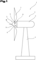
- Fig. 1 shows a schematic representation of a wind turbine 1 for generating electrical energy from wind energy.
- the wind turbine 1 comprises a nacelle 2, which is rotatably mounted on a tower 3.
- the nacelle 2 comprises a nacelle housing 4, which forms the main structure of the nacelle 2.
- the electrical components, such as a generator of the wind turbine 1, are arranged in the nacelle housing 4 of the nacelle 2.
- a rotor 5 is formed, which has a rotor hub 6 with rotor blades 7 arranged thereon.
- the rotor hub 6 is seen as part of the nacelle 2.
- the rotor hub 6 is rotatably mounted on the nacelle housing 4 by means of a rotor bearing 8.
- the axial force 10 is caused by the force of the wind.
- the radial force 9 is caused by the weight of the rotor 5 and acts on the center of gravity of the rotor 5. Since the center of gravity of the rotor 5 is outside the rotor bearing 8, the tilting moment 11 is caused in the rotor bearing 8 by the radial force 9.
- the tilting moment 11 can also be caused by an uneven load on the rotor blades 7.
- the rotor bearing 8 according to the invention can, for example, have a diameter between 0.5 m and 5 m. Of course, it is also conceivable that the rotor bearing 8 is smaller or larger.
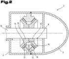
- Fig. 2 The nacelle housing 4 and the rotor hub 6 are shown in a schematic sectional view, whereby the structure, especially in its dimensions, has been highly schematized.
- the rotor bearing 8 has at least one inner ring element 12 and at least one outer ring element 13.
- At least one plain bearing element 14 is arranged between the inner ring element 12 and the outer ring element 13.
- the inner ring element 12 is coupled to the rotor hub 6.
- a rotor shaft 15 is formed on which the rotor hub 6 is arranged.
- the inner ring element 12 can be received directly on the rotor shaft 15.
- the inner ring element 12 is fastened to the nacelle housing 4 and that the rotor hub 6 is coupled to the outer ring element 13.
- both the inner ring element 12 and the outer ring element 13 are V-shaped and two sliding bearing elements 14 are formed on the V-shaped flank between the two ring elements 12, 13, spaced axially from each other, which are arranged at an angle to each other.
- the sliding bearing elements 14 are mounted directly on the inner ring element 12.
- a sliding surface 16 can be formed between the sliding bearing elements 14 and the outer ring element 13.
- the sliding surfaces 16 can also be arranged in a V shape.
- the inner ring element 12 is divided with respect to its axial extent or alternatively also along a central axis in order to facilitate the assembly of the rotor bearing 8.
- the inner ring element 12 is not as in Fig. 2 illustrated embodiment forms a groove, but the V-shaped arrangement is formed in reverse, so that a V-shaped projection is formed on the inner ring element 12.
- the outer ring element 13 is designed to be divided in its axial extent or alternatively also along a central axis.
- the individual parts of the split ring element 12, 13 are designed to be axially adjustable relative to one another in order to be able to compensate for the wear of the plain bearing elements 14, for example.
- the bearing gap can be adjusted by the axial adjustability of the individual parts of the ring elements 12, 13 relative to one another.
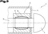
- FIG. 3 a further and possibly independent embodiment of the nacelle 2 is shown, whereby again the same reference numerals or component designations are used for the same parts as in the previous Figures 1 and 2 To avoid unnecessary repetition, please refer to the detailed description in the previous Figures 1 and 2 pointed out or referred to.
- the sliding bearing element 14 is designed as a coating which is applied directly to the inner ring element 12, wherein the inner ring element 12 is designed as an integral part of the rotor shaft 15 for receiving the rotor hub 6.
- the plain bearing element 14 has a sliding surface 16 in the form of a spherical cap.
- the plain bearing element 14 is designed for simultaneous radial and axial bearing of the rotor hub 6.
- the outer ring element 13 is designed as an integral part of a bearing block 17 accommodated in the nacelle housing 4.
- the bearing block 17 is divided along a central axis into an upper part and a lower part.
- the plain bearing element 14 is conical or V-shaped for simultaneous radial and axial bearing of the rotor hub 6.
- the plain bearing element 14 has a cylindrical radial plain bearing surface for simultaneous radial and axial bearing of the rotor hub 6 and has an axial plain bearing surface on the front side.
- This axial plain bearing surface can be designed in the form of a step, for example.
Landscapes
- Engineering & Computer Science (AREA)
- General Engineering & Computer Science (AREA)
- Mechanical Engineering (AREA)
- Sustainable Energy (AREA)
- Life Sciences & Earth Sciences (AREA)
- Sustainable Development (AREA)
- Manufacturing & Machinery (AREA)
- Chemical & Material Sciences (AREA)
- Combustion & Propulsion (AREA)
- Physics & Mathematics (AREA)
- Fluid Mechanics (AREA)
- Wind Motors (AREA)
- Sliding-Contact Bearings (AREA)
Abstract
Die Erfindung betrifft eine Gondel (2) für eine Windkraftanlage (1), die Gondel (2) umfassend:- ein Gondelgehäuse (4);- eine Rotornabe (6);- eine Rotorlagerung (8) zur Lagerung der Rotornabe (6) am Gondelgehäuse (4), wobei die Rotorlagerung (8) zumindest ein inneres Ringelement (12) und zumindest ein äußeres Ringelement (13) aufweist, wobei zwischen dem inneren Ringelement (12) und dem äußeren Ringelement (13) zumindest ein Gleitlagerelement (14) ausgebildet ist. Das Gleitlagerelement (14) ist untrennbar mit dem inneren Ringelement (12) verbunden ist oder dass das Gleitlagerelement (14) untrennbar mit dem äußeren Ringelement (13) verbunden.The invention relates to a nacelle (2) for a wind turbine (1), the nacelle (2) comprising: - a nacelle housing (4); - a rotor hub (6); - a rotor bearing (8) for mounting the rotor hub (6) on the nacelle housing (4), wherein the rotor bearing (8) has at least one inner ring element (12) and at least one outer ring element (13), wherein at least one plain bearing element (14) is formed between the inner ring element (12) and the outer ring element (13). The plain bearing element (14) is inseparably connected to the inner ring element (12) or the plain bearing element (14) is inseparably connected to the outer ring element (13).
Description
Die Erfindung betrifft eine Gondel mit einer Rotorlagerung für eine Windkraftanlage.The invention relates to a nacelle with a rotor bearing for a wind turbine.
Aus der
Die aus der
Aufgabe der vorliegenden Erfindung war es, die Nachteile des Standes der Technik zu überwinden und eine Gondel für eine Windkraftanlage zur Verfügung zu stellen, welche eine verbesserte Rotorlagerung aufweist. Weiters war es die Aufgabe der vorliegenden Erfindung ein Verfahren zum Herstellen der Gondel für die Windkraftanlage anzugeben.The object of the present invention was to overcome the disadvantages of the prior art and to provide a nacelle for a wind turbine which has an improved rotor bearing. Furthermore, the object of the present invention was to provide a method for producing the nacelle for the wind turbine.
Diese Aufgabe wird durch eine Vorrichtung und ein Verfahren gemäß den Ansprüchen gelöst.This object is achieved by a device and a method according to the claims.
Erfindungsgemäß ist eine Gondel für eine Windkraftanlage ausgebildet. Die Gondel umfasst:
- ein Gondelgehäuse;
- eine Rotornabe;
- eine Rotorlagerung zur Lagerung der Rotornabe am Gondelgehäuse, wobei die Rotorlagerung zumindest ein inneres Ringelement und zumindest ein äußeres Ringelement aufweist, wobei zwischen dem inneren Ringelement und dem äußeren Ringelement zumindest ein Gleitlagerelement ausgebildet ist. Das Gleitlagerelement ist untrennbar mit dem inneren Ringelement verbunden. Alternativ ist das Gleitlagerelement untrennbar mit dem äußeren Ringelement verbunden.
- a nacelle housing;
- a rotor hub;
- a rotor bearing for supporting the rotor hub on the nacelle housing, wherein the rotor bearing has at least one inner ring element and at least one outer ring element, wherein at least one plain bearing element is formed between the inner ring element and the outer ring element. The plain bearing element is inseparably connected to the inner ring element. Alternatively, the plain bearing element is inseparably connected to the outer ring element.
Das Gleitlagerelement weist eine Lauffläche auf. Die Lauffläche des Gleitlagerelementes wirkt mit einer Oberfläche des inneren Ringelementes zusammen, wenn das Gleitlagerelement untrennbar mit dem äußeren Ringelement verbunden ist. Die Lauffläche des Gleitlagerelementes wirkt mit einer Oberfläche des äußeren Ringelementes zusammen, wenn das Gleitlagerelement untrennbar mit dem inneren Ringelement verbunden ist.The plain bearing element has a running surface. The running surface of the plain bearing element interacts with a surface of the inner ring element when the plain bearing element is inseparably connected to the outer ring element. The running surface of the plain bearing element interacts with a surface of the outer ring element when the plain bearing element is inseparably connected to the inner ring element.
Die erfindungsgemäße Gondel, insbesondere die Rotorlagerung der Gondel, bringt den überraschenden Vorteil mit sich, dass sie einen einfachen Aufbau aufweist und wenig fehleranfällig ist bzw. eine hohe Lebensdauer aufweist.The nacelle according to the invention, in particular the rotor bearing of the nacelle, has the surprising advantage that it has a simple structure and is less susceptible to errors and has a long service life.
Weiters kann es zweckmäßig sein, wenn das innere Ringelement als integraler Bestandteil einer Rotorwelle zur Aufnahme der Rotornabe oder als integraler Bestandteil der Rotornabe selbst ausgebildet ist. Dies bringt eine weitere Vereinfachung des Aufbaues der Gondel und eine überraschende Erhöhung der Ausfallssicherheit mit sich.Furthermore, it can be useful if the inner ring element is designed as an integral part of a rotor shaft for receiving the rotor hub or as an integral part of the rotor hub itself. This further simplifies the structure of the nacelle and surprisingly increases reliability.
Ferner kann vorgesehen sein, dass das äußere Ringelement als integraler Bestandteil des Gondelgehäuses oder eines im Gondelgehäuse aufgenommenen Lagerbockes ausgebildet ist. Dies bringt eine weitere Vereinfachung des Aufbaues der Gondel und eine überraschende Erhöhung der Ausfallssicherheit mit sich.Furthermore, it can be provided that the outer ring element is designed as an integral part of the nacelle housing or of a bearing block accommodated in the nacelle housing. This brings about a further simplification of the structure of the nacelle and a surprising increase in reliability.
Als Gondelgehäuse wird die Gesamtheit der tragenden Gondelbauteile bezeichnet. Dies kann beispielsweise auch ein Gondelhauptrahmen der Gondel sein. Insbesondere kann vorgesehen sein, dass das äußere Ringelement im Gondelhauptrahmen ausgebildet ist.The nacelle housing is the entirety of the load-bearing nacelle components. This can also be, for example, a nacelle main frame. In particular, it can be provided that the outer ring element is formed in the nacelle main frame.
Wenn das äußere Ringelement als integraler Bestandteil eines im Gondelgehäuse aufgenommenen Lagerbockes ausgebildet ist, kann vorgesehen sein, dass der Lagerbock radial geteilt ausgebildet ist. Der Lagerbock kann beispielsweise in zwei Lagerbockhälften geteilt ausgebildet sein. Hierbei ist es denkbar, dass in beiden der Lagerbockhälften ein Teil des Gleitlagerelementes ausgebildet ist, bzw. mit diesen verbunden ist.If the outer ring element is designed as an integral component of a bearing block accommodated in the nacelle housing, it can be provided that the bearing block is designed to be radially divided. The bearing block can, for example, be divided into two bearing block halves. It is conceivable that a part of the plain bearing element is formed in both of the bearing block halves or is connected to them.
Mit anderen Worten ausgedrückt, kann das Gleitlagerelement zusammen mit dem das Gleitlagerelement aufnehmenden inneren Ringelement oder äußeren Ringelement radial oder auch axial geteilt ausgebildet sein.In other words, the plain bearing element can be designed to be radially or axially divided together with the inner ring element or outer ring element receiving the plain bearing element.
Darüber hinaus kann vorgesehen sein, dass das Gleitlagerelement stoffschlüssig mit dem inneren Ringelement verbunden ist oder dass das Gleitlagerelement stoffschlüssig mit dem äußeren Ringelement verbunden ist. Besonders eine derartige stoffschlüssige Verbindung des Gleitlagerelementes mit dem Ringelement bringt überraschende Erhöhung der Ausfallssicherheit mit sich. Besonders in Verbindung mit der Maßnahme wonach das innere Ringelement als integraler Bestandteil einer Rotorwelle zur Aufnahme der Rotornabe oder als integraler Bestandteil der Rotornabe selbst ausgebildet ist lassen sich zusätzliche Verbesserungen in der Ausfallsicherheit erzielen.In addition, it can be provided that the plain bearing element is integrally connected to the inner ring element or that the plain bearing element is integrally connected to the outer ring element. In particular, such an integral connection of the plain bearing element with the ring element brings with it a surprising increase in reliability. Additional improvements in reliability can be achieved, particularly in conjunction with the measure whereby the inner ring element is designed as an integral component of a rotor shaft for receiving the rotor hub or as an integral component of the rotor hub itself.
Vorteilhaft ist auch eine Ausprägung, gemäß welcher vorgesehen sein kann, dass das Gleitlagerelement als Beschichtung ausgebildet ist, welche direkt auf das innere Ringelement oder das äußere Ringelement aufgebracht ist. Eine direkt auf das Ringelement aufgebrachte Beschichtung ist besonders einfach und formgenau herzustellen.Another advantageous embodiment is one in which the plain bearing element can be designed as a coating that is applied directly to the inner ring element or the outer ring element. A coating applied directly to the ring element is particularly easy to produce and has a precise shape.
Gemäß einer Weiterbildung ist es möglich, dass das Gleitlagerelement zur gleichzeitigen Radiallagerung und Axiallagerung der Rotornabe ausgebildet ist. Dies bringt den Vorteil mich sich, dass für die Radiallagerung und die Axiallagerung der Rotornabe keine eigenen Lagerelemente ausgebildet sein müssen.According to a further development, it is possible for the plain bearing element to be designed for simultaneous radial and axial bearing of the rotor hub. This has the advantage that no separate bearing elements have to be designed for the radial bearing and the axial bearing of the rotor hub.
Weiters kann vorgesehen sein, dass das Gleitlagerelement im Bereich der Radiallagerung andere Materialeigenschaften aufweist, als im Bereich der Axiallagerung. Dies bringt den Vorteil mit sich, dass das Gleitlagerelement auf die jeweiligen unterschiedlichen Belastungen der Radiallagerung und der Axiallagerung angepasste Gleiteigenschaften aufweisen kann. Insbesondere kann vorgesehen sein, dass das Gleitlagerelement im Bereich der Radiallagerung eine höhere Festigkeit und/oder eine höhere Verschleißbeständigkeit aufweisen kann, als im Bereich der Axiallagerung.Furthermore, it can be provided that the plain bearing element has different material properties in the area of the radial bearing than in the area of the axial bearing. This has the advantage that the plain bearing element can have sliding properties adapted to the respective different loads of the radial bearing and the axial bearing. In particular, it can be provided that the plain bearing element can have a higher strength and/or a higher wear resistance in the area of the radial bearing than in the area of the axial bearing.
Ferner kann es zweckmäßig sein, wenn das Gleitlagerelement eine Gleitfläche in Form einer Kugelkalotte aufweist. Die Form einer Kugelkalotte ist einfach herzustellen und bringt darüber hinaus den Vorteil mit sich, dass eine effiziente Radiallagerung und gleichzeitig Axiallagerung der Rotornabe erreicht werden kann.It can also be useful if the plain bearing element has a sliding surface in the form of a spherical cap. The shape of a spherical cap is easy to manufacture and also has the advantage that efficient radial bearing and simultaneous axial bearing of the rotor hub can be achieved.
Darüber hinaus kann vorgesehen sein, dass das innere Ringelement und/oder das äußere Ringelement in Axialrichtung geteilt ausgebildet ist. Dies bringt den Vorteil mit sich, dass die Rotorlagerung einfach zusammengebaut werden kann.Furthermore, it can be provided that the inner ring element and/or the outer ring element is split in the axial direction. This has the advantage that the rotor bearing can be easily assembled.
Weiters kann vorgesehen sein, dass jenes Ringelement Axialrichtung geteilt ausgebildet ist, an welchem das Gleitlagerelement nicht angeordnet ist. Durch diese Maßnahme kann erreicht werden, dass die Rotorlagerung trotz der Möglichkeit, diese einfach zusammenzubauen, eine hohe Funktionalität im Einsatz und eine hohe Langlebigkeit aufweist.Furthermore, it can be provided that the ring element on which the plain bearing element is not arranged is split in the axial direction. This measure can ensure that the rotor bearing has a high level of functionality in use and a high level of durability, despite the possibility of simply assembling it.
Erfindungsgemäß ist ein Verfahren zum Herstellen einer Gondel für eine Windkraftanlage vorgesehen. Das Verfahren umfasst die Verfahrensschritte:
- Bereitstellen eines Gondelgehäuses;
- Bereitstellen einer Rotornabe;
- Bereitstellen einer Rotorlagerung zur Lagerung der Rotornabe am Gondelgehäuse, wobei die Rotorlagerung zumindest ein inneres Ringelement und zumindest ein äußeres Ringelement aufweist, wobei zwischen dem inneren Ringelement und dem äußeren Ringelement zumindest ein Gleitlagerelement ausgebildet ist. Zum Bereitstellen der Rotorlagerung wird das Gleitlagerelement untrennbar mit dem inneren Ringelement verbunden oder wird das Gleitlagerelement untrennbar mit dem äußeren Ringelement verbunden.
- Providing a nacelle housing;
- Providing a rotor hub;
- Providing a rotor bearing for supporting the rotor hub on the nacelle housing, wherein the rotor bearing has at least one inner ring element and at least one outer ring element, wherein at least one plain bearing element is formed between the inner ring element and the outer ring element. To provide the rotor bearing, the plain bearing element is inseparably connected to the inner ring element or the plain bearing element is inseparably connected to the outer ring element.
Das erfindungsgemäße Verfahren zum Herstellen einer Gondel, insbesondere der Rotorlagerung der Gondel, bringt den überraschenden Vorteil mit sich, dass es einfach durchzuführen ist, und somit wenig fehleranfällig ist, um eine Gondel mit einer hohen Lebensdauer herstellen zu können.The method according to the invention for producing a nacelle, in particular the rotor bearing of the nacelle, has the surprising advantage that it is easy to carry out and is therefore less prone to errors in order to be able to produce a nacelle with a long service life.
Entsprechend einer vorteilhaften Weiterbildung kann vorgesehen sein, dass das Gleitlagerelement durch Beschichten auf das innere Ringelement oder das äußere Ringelement aufgebracht wird. Eine direkt auf das Ringelement aufgebrachte Beschichtung ist besonders einfach und formgenau herzustellen.According to an advantageous further development, it can be provided that the plain bearing element is applied to the inner ring element or the outer ring element by coating. A coating applied directly to the ring element is particularly simple and precise to produce.
Insbesondere kann es vorteilhaft sein, wenn nach dem Beschichten des inneren Ringelementes oder des äußeren Ringelementes die Beschichtung durch mechanische Bearbeitung in die gewünschte Form gebracht wird. Durch diese Maßnahme lässt sich eine hochgenaue Rotorlagerung herstellen, welche somit eine lange Lebensdauer und exzellente Gleiteigenschaften aufweist.In particular, it can be advantageous if, after coating the inner ring element or the outer ring element, the coating is machined to the desired This measure enables the production of a highly precise rotor bearing, which therefore has a long service life and excellent sliding properties.
In einer alternativen Ausführungsvariante kann vorgesehen sein, dass das Gleitlagerelement durch Magnetpulsschweißen mittels eines Magnetkrafterzeugers auf das innere Ringelement oder das äußere Ringelement aufgebracht wird. besonders mittels des Verfahrens des Magnetpulsschweißens lassen sich Gleitlagerelemente mit hervorragenden Gleiteigenschaften funktionell in Gondeln von Windkraftanlagen integrieren.In an alternative embodiment, it can be provided that the plain bearing element is applied to the inner ring element or the outer ring element by magnetic pulse welding using a magnetic force generator. In particular, the magnetic pulse welding process can be used to functionally integrate plain bearing elements with excellent sliding properties into the nacelles of wind turbines.
Weiters kann vorgesehen sein, dass die Festigkeit des Gleitlagerelementes kleiner ist als die Festigkeit des inneren Ringelementes und des äußeren Ringelementes. Dies bringt den Vorteil mit sich, dass das Material des Lagerkörpers einfach an das Material des Trägerkörpers angepasst werden kann bzw. mit diesem verpresst werden kann.Furthermore, it can be provided that the strength of the plain bearing element is smaller than the strength of the inner ring element and the outer ring element. This has the advantage that the material of the bearing body can be easily adapted to the material of the carrier body or can be pressed together with it.
Weiters kann vorgesehen sein, dass am inneren Ringelement oder am äußeren Ringelement eine Oberflächenstrukturierung ausgebildet ist und dass zum Applizieren des Gleitlagerelementes am inneren Ringelement oder am äußeren Ringelement das Gleitlagerelement und das innere Ringelement oder das äußere Ringelement aneinandergepresst werden, wobei das Gleitlagerelement an einer Verbindungsfläche zum inneren Ringelement oder zum äußeren Ringelement durch Einwirkung der Oberflächenstrukturierung des inneren Ringelementes oder des äußeren Ringelementes plastisch verformt wird und eine formschlüssige Verbindung mit der Verbindungsfläche bildet. Durch diese Maßnahme kann erreicht werden, dass eine ausreichend festige Verbindung zwischen dem Gleitlagerelement und dem inneren Ringelement oder dem äußeren Ringelement erreicht werden kann, sodass die Rotorlagerung eine hohe Langzeitbeständigkeit aufweist und darüber hinaus einfach herzustellen ist.Furthermore, it can be provided that a surface structure is formed on the inner ring element or on the outer ring element and that in order to apply the plain bearing element to the inner ring element or to the outer ring element, the plain bearing element and the inner ring element or the outer ring element are pressed together, wherein the plain bearing element is plastically deformed at a connection surface to the inner ring element or to the outer ring element by the effect of the surface structure of the inner ring element or the outer ring element and forms a positive connection with the connection surface. This measure can ensure that a sufficiently strong connection can be achieved between the plain bearing element and the inner ring element or the outer ring element, so that the rotor bearing has a high long-term durability and is also easy to manufacture.
Weiters kann es zweckmäßig sein, wenn die Oberflächenstrukturierung der Verbindungsfläche Hinterschneidungen aufweist, in welche das Gleitlagerelementmaterial hineingepresst wird. Durch diese Maßnahme kann eine formschlüssige Verbindung zwischen dem inneren Ringelement oder dem äußeren Ringelement und dem Gleitlager erreicht werden.Furthermore, it can be useful if the surface structure of the connecting surface has undercuts into which the plain bearing element material is pressed. This measure can achieve a positive connection between the inner ring element or the outer ring element and the plain bearing.
Weiters kann vorgesehen sein, dass die Oberflächenstrukturierung mittels eines Lasers hergestellt wird.Furthermore, it can be provided that the surface structuring is produced by means of a laser.
In einer weiteren Alternativvariante kann vorgesehen sein, dass die Oberflächenstrukturierung durch ein 3D-Druck-Verfahren hergestellt wird.In another alternative variant, the surface structuring can be produced using a 3D printing process.
Ferner kann vorgesehen sein, dass die Oberflächenstrukturierung Stege aufweist, wobei die Stege beim Aneinanderpressen des Lagerkörpers und des Trägerkörpers verformt werden. Dies bringt den überraschenden Vorteil mit sich, dass die Verbindung zwischen dem Lagerkörper und dem Trägerkörper eine erhöhte Festigkeit aufweisen kann.Furthermore, it can be provided that the surface structure has webs, wherein the webs are deformed when the bearing body and the carrier body are pressed together. This brings with it the surprising advantage that the connection between the bearing body and the carrier body can have increased strength.
Darüber hinaus kann vorgesehen sein, dass die Stege im Wesentlichen im rechten Winkel zur Trägerkörperverbindungsfläche angeordnet sind.Furthermore, it can be provided that the webs are arranged substantially at right angles to the carrier body connection surface.
Vorteilhaft ist auch eine Ausprägung, gemäß welcher vorgesehen sein kann, dass sich die Stege während dem Aneinanderpressen des Lagerkörpers und des Trägerkörpers quer zu deren Längserstreckung verbiegen. Hierdurch kann überraschenderweise eine gute Verbindung zwischen dem Trägerkörper und dem Lagerkörper erreicht werden.Another advantageous embodiment is one in which the webs can be bent transversely to their longitudinal extension when the bearing body and the carrier body are pressed together. This surprisingly allows a good connection between the carrier body and the bearing body to be achieved.
Gemäß einer Weiterbildung ist es möglich, dass die Stege in einem Stegkopf eine Kopfquerschnittsbreite aufweisen und dass die Stege an einer Stegbasis eine Basisquerschnittsbreite aufweisen, wobei die Kopfquerschnittsbreite größer ist als die Basisquerschnittsbreite.According to a further development, it is possible for the webs in a web head to have a head cross-sectional width and for the webs at a web base to have a base cross-sectional width, wherein the head cross-sectional width is greater than the base cross-sectional width.
Ferner kann es zweckmäßig sein, wenn die Oberflächenstrukturierung der Trägerkörperverbindungsfläche mittels eines Umformverfahrens, insbesondere durch Rändeln, hergestellt wird. Besonders mittels einem derartigen Abwälzverfahren kann die benötigte Oberflächenstruktur des Trägerkörpers einfach hergestellt werden.Furthermore, it can be expedient if the surface structuring of the carrier body connection surface is produced by means of a forming process, in particular by knurling. The required surface structure of the carrier body can be produced easily, in particular by means of such a rolling process.
Ferner kann es zweckmäßig sein, wenn die Oberflächenstrukturierung der Verbindungsfläche Kreuzrändel oder Links-Rechtsrändel aufweist. Überraschenderweise bringt das Verfahren des Kreuzrändeln oder Links-Rechtsrändeln bzw. die dadurch hergestellten Oberflächen gegenüber allen anderen Oberflächenstrukturierungen oder glatten Oberflächen eine verbesserte Haltbarkeit zwischen dem Lagerkörper und dem Trägerkörper mit sich. Derartige Rändelverfahren sind in der DIN 8583-5, DIN 82, DIN 403 genormt. Insbesondere kann für die obig genannten Rändel laut Norm folgende Bezeichnung verwendet werden: RGE: Links-Rechtsrändel, Spitzen erhöht (Fischhaut); RGV: Links-Rechtsrändel, Spitzen vertieft; RKE: Kreuzrändel, Spitzen erhöht; RKV: Kreuzrändel, Spitzen vertieft.It can also be useful if the surface structure of the connecting surface has cross knurling or left-right knurling. Surprisingly, the process of cross knurling or left-right knurling or the surfaces produced thereby provide an improved Durability between the bearing body and the carrier body. Such knurling processes are standardized in DIN 8583-5, DIN 82, DIN 403. In particular, the following designation can be used for the knurls mentioned above according to the standard: RGE: left-right knurl, raised tips (fish skin); RGV: left-right knurl, recessed tips; RKE: cross knurl, raised tips; RKV: cross knurl, recessed tips.
Beim Rändeln wird zwischen dem spanlosen Rändeldrücken und dem spanenden Rändelfräsen unterschieden. Je nach Verfahren wird mit Rändelrädern das Profil hineingedrückt oder an einer Rändelfräse gefräst. An CNC-Drehmaschinen mit angetriebenen Werkzeugen können auch spezielle Rändelfräswerkzeuge eingesetzt werden, um ein Umspannen auf andere Maschinen zu vermeiden. Da die Bearbeitungskräfte beim Fräsen geringer ausfallen, findet es vorwiegend bei dünnen Werkstücken oder auf Bearbeitungszentren Verwendung.When knurling, a distinction is made between non-cutting knurling and cutting knurling. Depending on the process, the profile is pressed in with knurling wheels or milled on a knurling machine. Special knurling milling tools can also be used on CNC lathes with driven tools to avoid having to change the tool to another machine. Since the machining forces are lower when milling, it is mainly used for thin workpieces or on machining centers.
Insbesondere die obig beschriebenen durch Kreuzrändeln oder Links-Rechtsrändeln hergestellten Oberflächen in Verbindung mit einer zylindrisch oder in Form eines Zylindersegmentes ausgebildeten Trägerkörperverbindungsfläche und Lagerkörperverbindungsfläche bringen eine besonders verbesserte Haltbarkeit zwischen dem Trägerkörper und dem Lagerkörper mit sich.In particular, the surfaces produced by cross knurling or left-right knurling described above in conjunction with a carrier body connection surface and bearing body connection surface formed cylindrically or in the form of a cylinder segment bring about a particularly improved durability between the carrier body and the bearing body.
Weiters kann vorgesehen sein, dass das Gleitlagerelement durch Auftragschweißen direkt auf das innere Ringelement oder das äußere Ringelement hergestellt wird.Furthermore, it can be provided that the plain bearing element is manufactured by deposition welding directly onto the inner ring element or the outer ring element.
Entsprechend einer vorteilhaften Weiterbildung kann vorgesehen sein, dass die Schicht des auftraggeschweißten Materials eine Schichtdicke zwischen 0,5mm und 1,5mm, insbesondere zwischen 0,8mm und 1,2mm aufweist. Eine derartige Schichtdicke bringt den Vorteil mit sich, dass sie gute Gleiteigenschaften aufweisen kann, dabei verfahrenstechnisch gut herzustellen ist und darüber hinaus eine ausreichende Lebensdauer aufweisen kann.According to an advantageous further development, it can be provided that the layer of the welded material has a layer thickness of between 0.5 mm and 1.5 mm, in particular between 0.8 mm and 1.2 mm. Such a layer thickness has the advantage that it can have good sliding properties, is easy to produce in terms of process technology and can also have a sufficient service life.
Die Schichtdicke bemisst sich von der Oberfläche des Werkstückes vor dem Auftragschweißvorgang auf die Gleitoberfläche.The layer thickness is measured from the surface of the workpiece before the welding process to the sliding surface.
Insbesondere kann es vorteilhaft sein, wenn die Gleitoberfläche an der Schicht des auftraggeschweißten Materials eine gemittelte Rautiefe Rz zwischen 0,1 µm und 3,2 µm, insbesondere zwischen 0,5 µm und 1,6 µm aufweist. Besonders Oberflächen mit einer derartigen gemittelten Rautiefe Rz bringen gute Gleiteigenschaften mit sich und sind darüber hinaus an der Schicht des auftraggeschweißten Materials einfach herzustellen.In particular, it may be advantageous if the sliding surface on the layer of the welded material has an average roughness depth Rz between 0.1 µm and 3.2 µm, in particular between 0.5 µm and 1.6 µm. Surfaces with such an average roughness depth Rz in particular have good sliding properties and are also easy to produce on the layer of the welded material.
Ferner kann vorgesehen sein, dass das auftraggeschweißte Material aus einem Werkstoff besteht oder diesen umfasst, der ausgewählt ist aus einer Gruppe umfassend Aluminiumbasislegierungen, Zinnbasislegierungen, Bronzebasislegierungen, Messingbasislegierungen. Besonders derartige Werkstoffe bringen gute Gleiteigenschaften mit sich.Furthermore, it can be provided that the welded material consists of or comprises a material that is selected from a group comprising aluminum-based alloys, tin-based alloys, bronze-based alloys, brass-based alloys. Such materials in particular have good sliding properties.
Darüber hinaus kann vorgesehen sein, dass das auftraggeschweißte Material aus einem Werkstoff besteht oder diesen umfasst, der zumindest zwei Werkstoffe umfasst, die ausgewählt sind aus einer Gruppe umfassend Aluminium, Zinn, Bronze, Messing. Eine derartige Kombination aus mehreren Werkstoffen bringt den Vorteil mit sich, dass verschiedene positive Eigenschaften der einzelnen Werkstoffe vereint werden können, um neben guten Gleiteigenschaften auch eine große Langzeitbeständigkeit aufweisen zu können.In addition, it can be provided that the welded material consists of or comprises a material that comprises at least two materials selected from a group comprising aluminum, tin, bronze, brass. Such a combination of several materials has the advantage that various positive properties of the individual materials can be combined in order to be able to have good sliding properties as well as great long-term durability.
Vorteilhaft ist auch eine Ausprägung, gemäß welcher vorgesehen sein kann, dass für die Radiallagerung und die Axiallagerung auftraggeschweißte Materialien aus unterschiedlichen Werkstoffen ausgebildet sind. Hierdurch können verschiedene Materialien mit verschieden Materialeigenschaften miteinander kombiniert werden. Insbesondere kann hierdurch für die jeweils unterschiedlichen Belastungen der Radiallagerung und der Axiallagerung jeweils ein auftraggeschweißtes Material mit den für die jeweilige Belastung angepassten Eigenschaften verwendet werden.Another advantageous embodiment is one in which it can be provided that welded-on materials made of different materials are formed for the radial bearing and the axial bearing. This allows different materials with different material properties to be combined with one another. In particular, this means that a welded-on material with properties adapted to the respective load can be used for the different loads of the radial bearing and the axial bearing.
Die Verfahren des Thermischen Spritzens zählen ebenfalls zu den Oberflächenbeschichtungsverfahren. Laut der normativen Definition (DIN EN 657) werden dabei Zusatzwerkstoffe, die so genannten Spritzzusätze, innerhalb oder außerhalb eines Spritzbrenners ab-, an- oder aufgeschmolzen, in einem Gasstrom in Form von Spritzpartikeln beschleunigt und auf die Oberfläche des zu beschichtenden Bauteils geschleudert. Die Bauteiloberfläche wird dabei im Gegensatz zum Auftragschweißen nicht angeschmolzen und nur in geringem Maße thermisch belastet. Somit sind die Verfahren des Auftragschweißen und des Thermischen Spritzens auch eindeutig voneinander zu unterscheiden.Thermal spraying processes are also surface coating processes. According to the normative definition (DIN EN 657), additional materials, known as spray additives, are melted, heated or heated inside or outside a spray torch, accelerated in a gas stream in the form of spray particles and thrown onto the surface of the component to be coated. In contrast to build-up welding, the component surface is not melted and is only subjected to a small amount of thermal stress. This means that the build-up welding and thermal spraying processes can be clearly distinguished from one another.
Als untrennbare Verbindung im Sinne dieses Dokumentes wird jede Verbindung gesehen, welche nicht gelöst werden kann, ohne dabei das Gleitlagerelement und/oder das damit verbundene Ringelement in dessen Struktur zumindest teilweise zu zerstören. Eine Verbindung mittels eines lösbaren Befestigungsmittels, wie etwa einer Schraube, wird nicht als untrennbare Verbindung im Sinne dieses Dokumentes gesehen. Auch eine Verbindung mittels eines nur durch Zerstörung lösbaren Befestigungsmittels, wie etwa einer Niete, wird nicht als untrennbare Verbindung im Sinne dieses Dokumentes gesehen. Eine derartige untrennbare Verbindung kann beispielsweise eine stoffschlüssige Verbindung sein.An inseparable connection within the meaning of this document is any connection that cannot be separated without at least partially destroying the structure of the plain bearing element and/or the ring element connected to it. A connection using a detachable fastening means, such as a screw, is not considered an inseparable connection within the meaning of this document. A connection using a fastening means that can only be separated by destruction, such as a rivet, is also not considered an inseparable connection within the meaning of this document. Such an inseparable connection can, for example, be a material-bonded connection.
Als Gleitlagerelement in Form einer Beschichtung im Sinne dieses Dokumentes wird eine Schicht verstanden, welche durch Beschichten, einer Hauptgruppe der Fertigungsverfahren nach DIN 8580, auf einen Träger aufgebracht wird. Bei der Beschichtung kann es sich um eine dünne Schicht oder eine dicke Schicht sowie um mehrere in sich zusammenhängende Schichten handeln. Die Beschichtungsverfahren unterscheiden sich durch die Art der Schichtaufbringung in chemische, mechanische, thermische und thermomechanische Verfahren.A plain bearing element in the form of a coating within the meaning of this document is understood to be a layer that is applied to a substrate by coating, a main group of manufacturing processes according to DIN 8580. The coating can be a thin layer or a thick layer or several interconnected layers. The coating processes differ in the type of layer application into chemical, mechanical, thermal and thermomechanical processes.
Weiters kann vorgesehen sein, dass Laserauftragschweißen, insbesondere Laser-Pulver-Auftragschweißen, als Schweißverfahren verwendet wird.Furthermore, it can be provided that laser cladding, in particular laser powder cladding, is used as a welding process.
Es ist weiter möglich, dass auf dem Gleitlagerelement eine polymerbasierte Einlaufschicht angeordnet ist, um damit eine bessere Anpassungsfähigkeit der Gleitlagerlauffläche an die Gegenlauffläche während des Einlaufens des Gleitschicht zu erreichen, wobei zusätzlich von Vorteil ist, dass diese Einlaufschicht ebenfalls die Tribologie des Gleitlagers an sich verbessert. Dabei ist von Vorteil, dass diese polymerbasierte Einlaufschicht mit einem Sprühverfahren aufgetragen werden kann.It is also possible that a polymer-based running-in layer is arranged on the plain bearing element in order to achieve a better adaptability of the plain bearing running surface to the counter running surface during the running-in of the sliding layer, with the additional advantage that this running-in layer also improves the tribology of the plain bearing itself. It is advantageous that this polymer-based running-in layer can be applied using a spray process.
Alternativ dazu kann vorgesehen sein, dass das komplette Gleitlagerelement aus einem polymerbasierten Werkstoff gebildet ist. Dabei ist von Vorteil, dass das Gleitlagerelement mittels eines Sprühverfahrens direkt auf das innere Ringelement oder das äußere Ringelement aufgetragen werden kann.Alternatively, the entire plain bearing element can be made from a polymer-based material. The advantage here is that the plain bearing element can be applied directly to the inner ring element or the outer ring element using a spraying process.
Als Auftragschweißen oder Cladding nach DIN 8590 - "Beschichten durch Schweißen" wird ein Schweißvorgang bezeichnet, bei dem ausschließlich durch den Schweißzusatzwerkstoff, wie etwa Draht oder Pulver, ein Volumenaufbau, meist in Form einer Deckschicht, stattfindet. Hierbei wird die Bauteiloberfläche, auf die auftraggeschweißt wird, angeschmolzen. Es zählt somit zu den Oberflächenbeschichtungsverfahren.Cladding according to DIN 8590 - "Coating by welding" is a welding process in which the surface is coated exclusively by the welding filler material, such as wire or powder, a volume build-up takes place, usually in the form of a covering layer. In this case, the component surface onto which the build-up welding is carried out is melted. It is therefore one of the surface coating processes.
Zum besseren Verständnis der Erfindung wird diese anhand der nachfolgenden Figuren näher erläutert.For a better understanding of the invention, it is explained in more detail with reference to the following figures.
Es zeigen jeweils in stark vereinfachter, schematischer Darstellung:
- Fig. 1
- eine schematische Darstellung einer Windkraftanlage;
- Fig. 2
- ein Querschnitt eines ersten Ausführungsbeispiels einer Gondel in einer stark schematischen Darstellung;
- Fig. 3
- ein Querschnitt eines zweiten Ausführungsbeispiels einer Gondel in einer stark schematischen Darstellung.
- Fig. 1
- a schematic representation of a wind turbine;
- Fig. 2
- a cross-section of a first embodiment of a gondola in a highly schematic representation;
- Fig. 3
- a cross-section of a second embodiment of a gondola in a highly schematic representation.
Einführend sei festgehalten, dass in den unterschiedlich beschriebenen Ausführungsformen gleiche Teile mit gleichen Bezugszeichen bzw. gleichen Bauteilbezeichnungen versehen werden, wobei die in der gesamten Beschreibung enthaltenen Offenbarungen sinngemäß auf gleiche Teile mit gleichen Bezugszeichen bzw. gleichen Bauteilbezeichnungen übertragen werden können. Auch sind die in der Beschreibung gewählten Lageangaben, wie z.B. oben, unten, seitlich usw. auf die unmittelbar beschriebene sowie dargestellte Figur bezogen und sind diese Lageangaben bei einer Lageänderung sinngemäß auf die neue Lage zu übertragen.To begin with, it should be noted that in the different embodiments described, identical parts are provided with identical reference symbols or identical component designations, whereby the disclosures contained in the entire description can be transferred analogously to identical parts with identical reference symbols or identical component designations. The position information chosen in the description, such as top, bottom, side, etc., also refers to the figure directly described and shown, and these position information must be transferred analogously to the new position if the position changes.
Weiters ist ein Rotor 5 ausgebildet, welcher eine Rotornabe 6 mit daran angeordneten Rotorblättern 7 aufweist. Die Rotornabe 6 wird als Teil der Gondel 2 gesehen. Die Rotornabe 6 ist mittels einer Rotorlagerung 8 drehbeweglich am Gondelgehäuse 4 aufgenommen.Furthermore, a
Die Rotorlagerung 8, welche zur Lagerung der Rotornabe 6 am Gondelgehäuse 4 der Gondel 2 dient, ist zur Aufnahme einer Radialkraft 9, einer Axialkraft 10 und eines Kippmomentes 11 ausgebildet. Die Axialkraft 10 ist bedingt durch die Kraft des Windes. Die Radialkraft 9 ist bedingt durch die Gewichtskraft des Rotors 5 und greift am Schwerpunkt des Rotors 5 an. Da der Schwerpunkt des Rotors 5 außerhalb der Rotorlagerung 8 liegt, wird in der Rotorlagerung 8 durch die Radialkraft 9 das Kippmoment 11 hervorgerufen. Das Kippmoment 11 kann ebenfalls durch eine ungleichmäßige Belastung der Rotorblätter 7 hervorgerufen werden.The
Die erfindungsgemäße Rotorlagerung 8 kann beispielsweise einen Durchmesser zwischen 0,5 m und 5 m aufweisen. Natürlich ist es auch denkbar, dass die Rotorlagerung 8 kleiner oder größer ist.The
In
Wie aus
In wieder einem weiteren, nicht dargestellten Ausführungsbeispiel kann natürlich auch vorgesehen sein, dass das innere Ringelement 12 am Gondelgehäuse 4 befestigt ist, und dass die Rotornabe 6 mit dem äußeren Ringelement 13 gekoppelt ist.In yet another embodiment not shown, it can of course also be provided that the
Wie aus
Wie aus
In einem nicht dargestellten Ausführungsbeispiel ist es natürlich auch denkbar, dass das innere Ringelement 12 nicht wie im in
Sowohl bei einer Ausführung mit in axialer Erstreckung geteiltem inneren Ringelement 12, als auch bei einer Ausführung mit in axialer Erstreckung geteiltem äußeren Ringelement 13 kann vorgesehen sein, dass die Einzelteile des jeweils geteilt ausgeführten Ringelementes 12, 13 axial zueinander verstellbar ausgebildet sind, um beispielsweise den Verschleiß der Gleitlagerelemente 14 kompensieren zu können. Insbesondere kann vorgesehen sein, dass durch die axiale Verstellbarkeit der Einzelteile der Ringelemente 12, 13 zueinander der Lagerspalt eingestellt werden kann.Both in a design with an
In der
Wie aus
Das Gleitlagerelement 14 weist in diesem Ausführungsbeispiel eine Gleitfläche 16 in Form einer Kugelkalotte auf. Das Gleitlagerelement 14 ist hierbei zur gleichzeitigen Radiallagerung und Axiallagerung der Rotornabe 6 ausgebildet.In this embodiment, the
Wie aus
In einer weiteren, nicht dargestellten Ausführungsvariante kann vorgesehen sein, dass das Gleitlagerelement 14 ist zur gleichzeitigen Radiallagerung und Axiallagerung der Rotornabe 6 konusförmig oder V-förmig ausgebildet ist.In a further embodiment variant not shown, it can be provided that the
In einer weiteren, nicht dargestellten Ausführungsvariante kann vorgesehen sein, dass das Gleitlagerelement 14 zur gleichzeitigen Radiallagerung und Axiallagerung der Rotornabe 6 eine zylindrische Radial - Gleitlagerlauffläche aufweist und stirnseitig eine Axial- Gleitlagerlauffläche aufweist. Diese Axial- Gleitlagerlauffläche kann beispielsweise in Form einer Abstufung ausgebildet sein.In a further embodiment variant not shown, it can be provided that the
Die Ausführungsbeispiele zeigen mögliche Ausführungsvarianten, wobei an dieser Stelle bemerkt sei, dass die Erfindung nicht auf die speziell dargestellten Ausführungsvarianten derselben eingeschränkt ist, sondern vielmehr auch diverse Kombinationen der einzelnen Ausführungsvarianten untereinander möglich sind und diese Variationsmöglichkeit aufgrund der Lehre zum technischen Handeln durch gegenständliche Erfindung im Können des auf diesem technischen Gebiet tätigen Fachmannes liegt.The embodiments show possible embodiment variants, whereby it should be noted at this point that the invention is not restricted to the specifically illustrated embodiment variants thereof, but rather various combinations of the individual embodiment variants with each other are also possible and this possibility of variation lies within the skill of the person skilled in the art in this technical field due to the teaching of technical action through objective invention.
Der Schutzbereich ist durch die Ansprüche bestimmt. Die Beschreibung und die Zeichnungen sind jedoch zur Auslegung der Ansprüche heranzuziehen. Einzelmerkmale oder Merkmalskombinationen aus den gezeigten und beschriebenen unterschiedlichen Ausführungsbeispielen können für sich eigenständige erfinderische Lösungen darstellen. Die den eigenständigen erfinderischen Lösungen zugrundeliegende Aufgabe kann der Beschreibung entnommen werden.The scope of protection is determined by the claims. However, the description and the drawings are to be used to interpret the claims. Individual features or combinations of features from the different embodiments shown and described can represent independent inventive solutions. The independent The problem underlying the inventive solutions can be taken from the description.
Sämtliche Angaben zu Wertebereichen in gegenständlicher Beschreibung sind so zu verstehen, dass diese beliebige und alle Teilbereiche daraus mitumfassen, z.B. ist die Angabe 1 bis 10 so zu verstehen, dass sämtliche Teilbereiche, ausgehend von der unteren Grenze 1 und der oberen Grenze 10 mit umfasst sind, d.h. sämtliche Teilbereiche beginnen mit einer unteren Grenze von 1 oder größer und enden bei einer oberen Grenze von 10 oder weniger, z.B. 1 bis 1,7, oder 3,2 bis 8,1, oder 5,5 bis 10.All information on value ranges in the description in question is to be understood as including any range and all subranges thereof, e.g. the
Der Ordnung halber sei abschließend darauf hingewiesen, dass zum besseren Verständnis des Aufbaus Elemente teilweise unmaßstäblich und/oder vergrößert und/oder verkleinert dargestellt wurden.Finally, for the sake of clarity, it should be noted that, in order to better understand the structure, some elements have been shown not to scale and/or enlarged and/or reduced.
- 11
- Windkraftanlagewind turbine
- 22
- Gondelgondola
- 33
- TurmTower
- 44
- Gondelgehäusenacelle housing
- 55
- Rotorrotor
- 66
- Rotornaberotor hub
- 77
- Rotorblattrotor blade
- 88
- Rotorlagerungrotor bearing
- 99
- Radialkraftradial force
- 1010
- Axialkraftaxial force
- 1111
- Kippmomenttipping moment
- 1212
- inneres Ringelementinner ring element
- 1313
- äußeres Ringelementouter ring element
- 1414
- Gleitlagerelementplain bearing element
- 1515
- Rotorwellerotor shaft
- 1616
- Gleitflächesliding surface
- 1717
- Lagerbockbearing block
Claims (14)
Applications Claiming Priority (3)
| Application Number | Priority Date | Filing Date | Title |
|---|---|---|---|
| DE102020112765.0A DE102020112765A1 (en) | 2020-05-12 | 2020-05-12 | Main rotor bearing of a nacelle for a wind turbine |
| EP21728411.6A EP4150224B1 (en) | 2020-05-12 | 2021-05-07 | Rotor main bearing of a nacelle for a wind turbine |
| PCT/AT2021/060159 WO2021226645A1 (en) | 2020-05-12 | 2021-05-07 | Rotor main bearing of a nacelle for a wind turbine |
Related Parent Applications (1)
| Application Number | Title | Priority Date | Filing Date |
|---|---|---|---|
| EP21728411.6A Division EP4150224B1 (en) | 2020-05-12 | 2021-05-07 | Rotor main bearing of a nacelle for a wind turbine |
Publications (1)
| Publication Number | Publication Date |
|---|---|
| EP4477902A1 true EP4477902A1 (en) | 2024-12-18 |
Family
ID=76180816
Family Applications (2)
| Application Number | Title | Priority Date | Filing Date |
|---|---|---|---|
| EP24194950.2A Withdrawn EP4477902A1 (en) | 2020-05-12 | 2021-05-07 | Rotor main bearing of a nacelle for a wind turbine |
| EP21728411.6A Active EP4150224B1 (en) | 2020-05-12 | 2021-05-07 | Rotor main bearing of a nacelle for a wind turbine |
Family Applications After (1)
| Application Number | Title | Priority Date | Filing Date |
|---|---|---|---|
| EP21728411.6A Active EP4150224B1 (en) | 2020-05-12 | 2021-05-07 | Rotor main bearing of a nacelle for a wind turbine |
Country Status (7)
| Country | Link |
|---|---|
| US (1) | US11873858B2 (en) |
| EP (2) | EP4477902A1 (en) |
| CN (1) | CN115516220B (en) |
| DE (1) | DE102020112765A1 (en) |
| DK (1) | DK4150224T3 (en) |
| ES (1) | ES2993673T3 (en) |
| WO (1) | WO2021226645A1 (en) |
Families Citing this family (2)
| Publication number | Priority date | Publication date | Assignee | Title |
|---|---|---|---|---|
| CN221974112U (en) * | 2023-12-21 | 2024-11-08 | 金雷科技股份公司 | Wind-powered electricity generation main shaft integration slide bearing transmission system |
| DE102024122667A1 (en) * | 2024-08-08 | 2026-02-12 | Schaeffler Technologies AG & Co. KG | Main bearing housing; main bearing for a wind turbine rotor; wind turbine with one rotor; method for performing service work on a main bearing |
Citations (8)
| Publication number | Priority date | Publication date | Assignee | Title |
|---|---|---|---|---|
| AT509625A1 (en) * | 2010-04-14 | 2011-10-15 | Miba Gleitlager Gmbh | BEARING ELEMENT |
| EP2694810A2 (en) | 2011-09-08 | 2014-02-12 | Siemens Aktiengesellschaft | Direct-drive wind turbine |
| WO2014117197A1 (en) * | 2013-01-30 | 2014-08-07 | Miba Gleitlager Gmbh | Wind power plant gear mechanism |
| WO2015110138A1 (en) * | 2014-01-21 | 2015-07-30 | Aktiebolaget Skf | Pitch bearing construction comprising spherical plain bearings |
| EP3309393A1 (en) * | 2016-10-12 | 2018-04-18 | Linde Hydraulics GmbH & Co. KG | Hydrostatic fluid displacement machine |
| WO2018071941A1 (en) * | 2016-10-21 | 2018-04-26 | Miba Gleitlager Austria Gmbh | Bearing element |
| WO2019020213A1 (en) * | 2017-07-25 | 2019-01-31 | Rheinisch-Westfälische Technische Hochschule Aachen | SYSTEM OF SMOOTH BEARINGS |
| WO2019178630A1 (en) * | 2018-03-23 | 2019-09-26 | Miba Gleitlager Austria Gmbh | Wind turbine gearbox and method for producing a wind turbine gearbox |
Family Cites Families (2)
| Publication number | Priority date | Publication date | Assignee | Title |
|---|---|---|---|---|
| DE4008671A1 (en) * | 1990-03-17 | 1991-10-10 | Glyco Metall Werke | Radial-axial sliding bearing - has sprayed metal to form bearing surface at axial sections |
| AT15975U1 (en) * | 2017-05-23 | 2018-10-15 | Miba Gleitlager Austria Gmbh | Wind Turbine Gearbox |
-
2020
- 2020-05-12 DE DE102020112765.0A patent/DE102020112765A1/en not_active Ceased
-
2021
- 2021-05-07 US US17/923,256 patent/US11873858B2/en active Active
- 2021-05-07 ES ES21728411T patent/ES2993673T3/en active Active
- 2021-05-07 WO PCT/AT2021/060159 patent/WO2021226645A1/en not_active Ceased
- 2021-05-07 EP EP24194950.2A patent/EP4477902A1/en not_active Withdrawn
- 2021-05-07 CN CN202180033403.4A patent/CN115516220B/en active Active
- 2021-05-07 DK DK21728411.6T patent/DK4150224T3/en active
- 2021-05-07 EP EP21728411.6A patent/EP4150224B1/en active Active
Patent Citations (9)
| Publication number | Priority date | Publication date | Assignee | Title |
|---|---|---|---|---|
| AT509625A1 (en) * | 2010-04-14 | 2011-10-15 | Miba Gleitlager Gmbh | BEARING ELEMENT |
| EP2694810A2 (en) | 2011-09-08 | 2014-02-12 | Siemens Aktiengesellschaft | Direct-drive wind turbine |
| EP2694810B1 (en) | 2011-09-08 | 2015-11-25 | Siemens Aktiengesellschaft | Direct-drive wind turbine |
| WO2014117197A1 (en) * | 2013-01-30 | 2014-08-07 | Miba Gleitlager Gmbh | Wind power plant gear mechanism |
| WO2015110138A1 (en) * | 2014-01-21 | 2015-07-30 | Aktiebolaget Skf | Pitch bearing construction comprising spherical plain bearings |
| EP3309393A1 (en) * | 2016-10-12 | 2018-04-18 | Linde Hydraulics GmbH & Co. KG | Hydrostatic fluid displacement machine |
| WO2018071941A1 (en) * | 2016-10-21 | 2018-04-26 | Miba Gleitlager Austria Gmbh | Bearing element |
| WO2019020213A1 (en) * | 2017-07-25 | 2019-01-31 | Rheinisch-Westfälische Technische Hochschule Aachen | SYSTEM OF SMOOTH BEARINGS |
| WO2019178630A1 (en) * | 2018-03-23 | 2019-09-26 | Miba Gleitlager Austria Gmbh | Wind turbine gearbox and method for producing a wind turbine gearbox |
Also Published As
| Publication number | Publication date |
|---|---|
| EP4150224B1 (en) | 2024-08-21 |
| WO2021226645A1 (en) | 2021-11-18 |
| DE102020112765A1 (en) | 2021-11-18 |
| US11873858B2 (en) | 2024-01-16 |
| EP4150224A1 (en) | 2023-03-22 |
| CN115516220A (en) | 2022-12-23 |
| CN115516220B (en) | 2025-03-04 |
| ES2993673T3 (en) | 2025-01-03 |
| DK4150224T3 (en) | 2024-11-18 |
| US20230313833A1 (en) | 2023-10-05 |
Similar Documents
| Publication | Publication Date | Title |
|---|---|---|
| EP3768983B1 (en) | Wind turbine gearbox and method for producing a wind turbine gearbox | |
| EP3529508B1 (en) | Bearing element | |
| AT521882B1 (en) | Plain bearings, in particular for a gearbox of a wind turbine | |
| AT513516B1 (en) | Wind Turbine Gearbox | |
| AT524520B1 (en) | Plain bearing, and a gondola equipped with the plain bearing for a wind turbine | |
| EP4150224B1 (en) | Rotor main bearing of a nacelle for a wind turbine | |
| WO2020232495A1 (en) | Nacelle for a wind turbine | |
| WO2008031522A1 (en) | Method for producing a connecting rod | |
| DE102010014689A1 (en) | Coating a surface of a workpiece, comprises producing groove recesses having undercuts in the surface to be coated, and subsequently applying a layer, so that the material forming the layer fills the groove recesses having the undercuts | |
| EP1003924B1 (en) | Method for thermal coating, especially for plain bearings | |
| EP4219970B1 (en) | METHOD FOR MANUFACTURING A MULTI-LAYER SLIDING BEARING | |
| DE102010039778B4 (en) | Rotor blade for wind turbines | |
| EP3976286B1 (en) | Multilayer slide bearing and method for producing a multilayer slide bearing | |
| EP1048389A2 (en) | Cover used for the upper surface of a workpiece | |
| EP4446604A1 (en) | Multilayer sliding bearing, wind turbine transmission equipped with multilayer sliding bearing, and method for producing a multilayer sliding bearing | |
| EP2206586B1 (en) | Segment of a chain saw for high-speed chain sawing for sawing masonry, concrete, bricks and metal | |
| DE102005022013B4 (en) | Fluid dynamic thrust bearing and method for connecting components of a fluid dynamic thrust bearing | |
| AT524211A4 (en) | Method for connecting a first component to a second component to form an assembly | |
| WO2024081982A1 (en) | Plain bearing element | |
| WO1999006613A1 (en) | Tool for working workpieces and method for producing said tool | |
| EP3850234A1 (en) | Method for producing rolling bearing cages, in particular large rolling bearing cages, and rolling bearing cages | |
| EP3431749B1 (en) | Extender for fixing a rotor blade to a rotor hub housing of a wind turbine, method for producing an extender and method for mounting an extender | |
| EP4015776A1 (en) | Rotor disc and rotor blade for an airjet engine gas turbine compressor or turbine stage | |
| EP0399319A2 (en) | Hinge fitting for motor vehicle seats |
Legal Events
| Date | Code | Title | Description |
|---|---|---|---|
| PUAI | Public reference made under article 153(3) epc to a published international application that has entered the european phase |
Free format text: ORIGINAL CODE: 0009012 |
|
| STAA | Information on the status of an ep patent application or granted ep patent |
Free format text: STATUS: THE APPLICATION HAS BEEN PUBLISHED |
|
| AC | Divisional application: reference to earlier application |
Ref document number: 4150224 Country of ref document: EP Kind code of ref document: P |
|
| AK | Designated contracting states |
Kind code of ref document: A1 Designated state(s): AL AT BE BG CH CY CZ DE DK EE ES FI FR GB GR HR HU IE IS IT LI LT LU LV MC MK MT NL NO PL PT RO RS SE SI SK SM TR |
|
| STAA | Information on the status of an ep patent application or granted ep patent |
Free format text: STATUS: THE APPLICATION IS DEEMED TO BE WITHDRAWN |
|
| 18D | Application deemed to be withdrawn |
Effective date: 20250619 |