EP2206586B1 - Segment of a chain saw for high-speed chain sawing for sawing masonry, concrete, bricks and metal - Google Patents
Segment of a chain saw for high-speed chain sawing for sawing masonry, concrete, bricks and metal Download PDFInfo
- Publication number
- EP2206586B1 EP2206586B1 EP20090016116 EP09016116A EP2206586B1 EP 2206586 B1 EP2206586 B1 EP 2206586B1 EP 20090016116 EP20090016116 EP 20090016116 EP 09016116 A EP09016116 A EP 09016116A EP 2206586 B1 EP2206586 B1 EP 2206586B1
- Authority
- EP
- European Patent Office
- Prior art keywords
- segment
- outer links
- links
- cutting
- saw chain
- Prior art date
- Legal status (The legal status is an assumption and is not a legal conclusion. Google has not performed a legal analysis and makes no representation as to the accuracy of the status listed.)
- Active
Links
Images
Classifications
-
- B—PERFORMING OPERATIONS; TRANSPORTING
- B28—WORKING CEMENT, CLAY, OR STONE
- B28D—WORKING STONE OR STONE-LIKE MATERIALS
- B28D1/00—Working stone or stone-like materials, e.g. brick, concrete or glass, not provided for elsewhere; Machines, devices, tools therefor
- B28D1/02—Working stone or stone-like materials, e.g. brick, concrete or glass, not provided for elsewhere; Machines, devices, tools therefor by sawing
- B28D1/12—Saw-blades or saw-discs specially adapted for working stone
- B28D1/124—Saw chains; rod-like saw blades; saw cables
Definitions
- the invention relates to a segment of a saw chain for high-speed chainsaws for sawing rock, concrete, brick and metal. Such a segment is in the WO 2008/041263 A1 discloses, from which the features of the preamble of claim 1 are known.
- the known chain systems which are suitable for the machining of hard materials such as rock, concrete, brick and metal have chain segments, the members of which are connected transversely to the direction of metal rivets or metal bolts on which the members rotatably support, with each other.
- This construction leads to large chain widths.
- the metal bolts or rivets are also made of relatively soft material, which makes them always worn in the same place, resulting in elongation of the saw chains. The elongation must be compensated by adjusting the saw chain, which leads to failure of the saws and additional repair work with the associated costs.
- From the DE 1 148 481 is a sawing chain for rock known whose segments consist of outer links and inner links, which are connected transversely to the direction of rivets. On the outer and / or inner links grinding materials are arranged, whose distance is only 0.2 to 0.8 mm and which are made wider than the links of the chain. However, the connection of the outer and inner links is made by the conventionally known and wear metal bolt connection.
- the DE 103 11 915 A1 discloses a wear-resistant transport chain, in which outer links, tabs, sleeves and pins ( Fig.1, 2 and 5) surfaces or surface portions of individual parts subject to particular wear are coated with a diamond-like amorphous carbon (DLC) layer. These surfaces may also have metallic particles distributed in the DLC layer and made of tungsten, chromium or titanium.
- This chain design reduces the wear of the chain parts but does not eliminate it. In addition, it is not subject to the high stress of a saw chain for rock.
- a wear-improved timing chain and a method for the production thereof in which elements of the chain, in particular connecting bolt hollow pins, sleeves flaps or rollers in the region of their surface have a coating of a Gleitstoff für or a combination of a hard material and a Gleitstoff für.
- These layers can consist of many different hard metals and their alloys as well as polymers or organic bonded coatings.
- hard-material layers of a nidritic, carbidic and / or carbonitride-type which are applied by all customary dip, spray, powder and PVD / CVD methods, can be applied under the sliding layers.
- the layer thicknesses are between 1 and 15 microns.
- the disclosed chain parts are low-wear but not wear-resistant. In addition, their production is very time consuming only by the required coatings before installation.
- the fasteners made of wear-resistant ceramic material and end roughened peripheral surfaces and the outer members consist of a shrinkable steel and have at least two through holes and at least one in the direction of right-angled tab, the roughened peripheral surfaces with the through holes of two opposing outer members by a shrink-fit and the tabs are positively connected to each other, wherein the end faces of the connecting elements with the outer surfaces of the outer members form a plane.
- the cutting segment are each connected to the upper edges and the tabs of two opposing outer members frictionally with each other.
- a welded connection is preferred for the adhesion of the parts.
- This composite ensures a solid Seat of the cutting segments on the outer links and additionally supports the strength of the composite of the outer links with the connecting elements. Since the cut segments are wider than the segments of the saw chain, only the cut segments are subject to wear but not the chain segments. The saw chain is thus not only wear-free but also maintenance-free.
- the simple design of the individual parts of a segment and their small number in connection with the joining and joining method used is particularly advantageous because it allows an automated and thus easy and fast assembly of the segments and thus time and cost can be produced.
- the wear and maintenance-free structure of the saw chain according to the invention ensures despite these considerable advantages over the prior art, the offer of a low-priced tool that can be disposed of after consumption of the cutting segments.
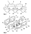
- two erfindugssecuree segments 1 a saw chain in combination and their individual parts are shown. They consist of two successively arranged in the direction of pairs of outer members 2, which consist for example of a shrinkable heat-treated steel, two in the direction of juxtaposed through holes 2.1 and at its lower edge 2.5 each center in the direction of a right-angled tab 2.2 and in which each have a pair Outer members 2 is arranged opposite one another so that the passage openings 2.1 are opposite transversely to the direction and the tabs facing each other 2.2.
- three inner members 3 are arranged one behind the other in the running direction, which consist for example of alloyed stainless steel X153CrMoV12, 12379, a triangular shape with a top edge 3.2 and two parallel to this passage opening 3.1 two opposite to the cutting direction edges 3.3, the form a corner 3.5 and each have a molded circular segment-shaped recesses 3.4.
- the inner members 3 are arranged with their upper edge 2.4 in the cutting direction between the outer members 2, that always a passage opening 3.1 of an inner member 3 transversely to the direction with two opposing through holes 2.1 of two opposite outer members 2 corresponds.
- the second through opening 3.1 of the same inner member 3 then corresponds to the opposing first through openings 2.1 of the following pair of two opposing outer members 2, etc.
- the connecting elements 4 are preferably made of a wear-resistant sintered zirconium oxide and were produced, for example, as a hollow cylinder.
- the connecting elements 4 have a length which corresponds approximately to the sum of the material thicknesses of the respectively opposite two outer members 2 and the inner member 3 located therebetween.
- the outer diameter of the connecting elements 4 corresponds in the central region approximately to the inner diameter of the passage openings 3.1 of the inner member 3.
- Two end-shaped peripheral surfaces 4.1 are provided for example with a knurling.
- the outer diameter of the peripheral surfaces 4.1 corresponds approximately to the inner diameter of the passage openings 2.1 and the length of the material thickness of the outer members 2 and the end faces 4.2 of the connecting elements 4 are flat.
- a connecting element 4 is rotatably mounted with its central outer diameter in a through hole 3.1 of an inner member 3 and is with his Endally molded peripheral surfaces 4.1 in two adjacent to both outer surfaces of the inner member 3 through holes 2.1 of two opposing outer members 2 by a shrink and press fit anchored so that the outer surfaces 2.3 of the outer members 2 with the end faces 4.2 of the connecting elements 4 form a plane.
- each of the two inner members 3 projecting towards each other ends of the integrally formed on the lower edges 2.5 of the outer members 2 tabs 2.2 are welded together.
- a commercially available cutting segment 5 is, for example, welded on the upper edges 2.4 of two opposing outer members 2 in such a way that it projects beyond the body of each segment 1 on both sides in the running direction.
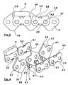
- the second embodiment according to Fig.3 and Fig.4 shows two segments of a saw chain 1 according to the invention in the composite and their individual parts, wherein the outer members 2 additionally have at its upper edge 2.4 a second formed in the direction of tab 2.2.
- the inner links 3 are executed in a square shape with rounded corners and two arranged in the direction between two corners through holes 3.1 and arranged as a rhombus between the outer members 2.
- a in the cutting direction on the upper edge 2.4 of the outer members 2 protruding corner 3.6 has a rectangular recess 3.7 and serves as Räum leopard and an opposite on the lower edge of the outer members 2 2 protruding corner serves as a transport member of the segment 1.
- FIG. 3 shown composite of two segments 1 shows that only one segment 1 over the two upper edges 2.4 of the outer members 2 with a sectional segment 5 and the two tabs 2.2 at the upper edge 2.4 and the two tabs 2.2 at the lower edge 2.5 of the outer members 2 is welded , A following segment 1 is welded as a dummy segment only over the middle of the upper edge 2.4 and at the lower edge 2.5 of the outer members 2 at right angles to the direction of formed and against each other directed tabs 2.2.
- the connecting elements 4 are made in this example as solid bolts of a ceramic base material, however, have the same outer contour as described in Example 1 and consist for example of a zirconium-reinforced alumina.
Description
Die Erfindung betrifft ein Segment einer Sägekette für hochtourige Motorsägen zum Sägen von Gestein, Beton, Ziegel und Metall. Ein derartiges Segment wird in dem
Die bekannten Kettensysteme, die für die Bearbeitung von harten Materialien wie Gestein, Beton, Ziegel und Metall geeignet sind weisen Kettensegmente auf, deren Glieder quer zur Laufrichtung mit Metallnieten oder Metallbolzen auf denen die Glieder drehbar lagern, miteinander verbunden sind. Diese Bauweise führt zu großen Kettenbreiten. Die Metallbolzen oder -nieten bestehen außerdem aus verhältnismäßig weichem Material, wodurch sie immer an der gleichen Stelle abgenutzt werden, was zu einer Längung der Sägeketten führt. Die Längung muß durch Nachstellung der Sägekette ausgeglichen werden, was zum Ausfall der Sägen und zusätzlichem Reparaturaufwand mit den damit verbundenen Kosten führt.The known chain systems which are suitable for the machining of hard materials such as rock, concrete, brick and metal have chain segments, the members of which are connected transversely to the direction of metal rivets or metal bolts on which the members rotatably support, with each other. This construction leads to large chain widths. The metal bolts or rivets are also made of relatively soft material, which makes them always worn in the same place, resulting in elongation of the saw chains. The elongation must be compensated by adjusting the saw chain, which leads to failure of the saws and additional repair work with the associated costs.
Diesem Problem wurde von einigen Herstellern durch Einsatz abgedichteter Metallbolzen durch O- Ringe und Schmierung der Bolzen entgegengetreten. Derartige Kettenkonstruktionen haben eine zwar eingeschränkte Längung der Ketten zur Folge, nicht aber deren Beseitigung.This problem has been addressed by some manufacturers by using sealed metal bolts through O-rings and bolt lubrication. Such chain constructions have a limited elongation of the chains result, but not their removal.
Aus der
Aus der
Die
Schließlich ist aus der
Es war daher Aufgabe der Erfindung ein Segment für eine Sägekette zum Sägen von Gestein, Beton, Ziegel und Metall zu finden, das eine Längung der Kette unterbindet, dessen Bestandteile bis auf das Schnittsegement selbst verschleißfrei und somit wartungsfrei sind, das einen schmalen Bauraum aufweist und durch einen automatisierten Herstellungsprozeß schnell und einfach gefügt werden kann.It was therefore an object of the invention to find a segment for a saw chain for sawing rock, concrete, brick and metal, which prevents elongation of the chain, its components except for the Schnittsegement itself wear-free and thus maintenance-free, which has a narrow space and can be joined quickly and easily by an automated manufacturing process.
Die Aufgabe wird mit den Merkmalen des Anspruchs 1 gelöst. Besonders hervorzuheben ist dabei, daß die Verbindungselemente aus verschleißfestem Keramikmaterial bestehen und endseitig aufgerauhte Umfangsflächen aufweisen und die Außenglieder, gemäß Anspruch 2, aus einem schrumpfungsfähigen Stahl bestehen und mindestens zwei Durchgangsöffnungen sowie mindestens eine in Laufrichtung rechtwinklig angeformte Lasche aufweisen, die aufgerauhten Umfangsflächen mit den Durchgangsöffnungen von zwei gegenüberliegenden Außengliedern durch einen Schrumpf- Preßsitz und die Laschen miteinander kraftschlüssig verbunden sind, wobei die Stirnflächen der Verbindungselemente mit den Außenflächen der Außenglieder eine Ebene bilden.The object is achieved with the features of claim 1. Particularly noteworthy is the fact that the fasteners made of wear-resistant ceramic material and end roughened peripheral surfaces and the outer members, according to
Dieser konstruktive Aufbau gewährleistet einen sehr schmalen Baurraum der Kette. Durch die individuelle Gestaltung der Verbindungselemente, gemäß Anspruch 5, wird darüber hinaus eine optimale Formschlüssigkeit und damit Festigkeit der Verbindung zwischen dem keramischen Verbindungselement und den metallischen Außengliedern geschaffen.This structural design ensures a very narrow space of the chain. Due to the individual design of the connecting elements, according to
Von großem Vorteil sind des weiteren die zwischen zwei gegenüberliegenden Außengliedern, über jeweils eine erste Durchgangsöffnung auf einem ersten Verbindungselement des einen Segmentes und über eine zweite Durchgangsöffnung auf dem zweiten Verbindungselement des folgenden Segmentes um deren Achsen drehbar lagernden Innenglieder, die, gemäß Anspruch 3, aus einem sehr harten Material bestehen, wobei sie die Segmente der Sägekette miteinander verbinden. Durch die Materialwahl der Innenglieder und der darin drehbar gelagerten Verbindungselemente wird die Verschleißlosigkeit beider Teile unterstützt und vor allem die Längung einer Kette, die aus den erfindungegemäßen Segmenten montiert ist, ausgeschlossen.Of great advantage are further between two opposite outer members, each having a first passage opening on a first connecting element of a segment and a second passage opening on the second connecting element of the following segment about the axes rotatably supporting inner members, which, according to
Vorteilhaft ist außerdem, daß das Schnittsegment jeweils mit den Oberkanten und die Laschen zweier gegenüberliegender Außenglieder kraftschlüssig miteinander verbunden sind. Gemäß Anspruch 6 wird für den Kraftschluß der Teile eine Schweißverbindung bevorzugt. Dieser Verbund sichert einen festen Sitz der Schnittsegmente auf den Außengliedern und unterstützt zusätzlich die Festigkeit des Verbundes der Außenglieder mit den Verbindungselementen. Da die Schnittsegmente breiter sind als die Segmente der Sägekette unterliegen nur die Schnittsegmente einem Verschleiß nicht aber die Kettensegmente. Die Sägekette ist dadurch nicht nur verschleißfrei sondern auch wartungsfrei.It is also advantageous that the cutting segment are each connected to the upper edges and the tabs of two opposing outer members frictionally with each other. According to claim 6, a welded connection is preferred for the adhesion of the parts. This composite ensures a solid Seat of the cutting segments on the outer links and additionally supports the strength of the composite of the outer links with the connecting elements. Since the cut segments are wider than the segments of the saw chain, only the cut segments are subject to wear but not the chain segments. The saw chain is thus not only wear-free but also maintenance-free.
Hervorzuheben ist auch eine zweite Variante der erfindungsgemäßen Segmente bei der die Innenglieder, gemäß Anspruch 4, eine Bauform mit angeformten Räumzähnen aufweisen und die Außenglieder an ihrer Ober- und Unterkante mit abgewinkelten Laschen ausgestattet sind. Diese Variante gestattet, daß nur jedes zweite Segment mit einem Schnittsegment ausgestattet werden muß und das die Außenglieder, insbesondere diejenigen die als Blindglied eingebaut sind, über die angeformten Laschen an Ihrer Ober- und Unterkante verschweißt sind und dem Segmentverbund eine zusätzliche Stabilität verleihen. Aufgrund der Einsparung von Schnittsegmenten ist diese Variante hinsichtlich des Materialaufwandes etwas wirtschaftlicher.Also to emphasize is a second variant of the segments according to the invention in which the inner members, according to claim 4, have a design with integrally formed Räumzähnen and the outer members are equipped at their upper and lower edges with angled tabs. This variant allows that only every other segment must be equipped with a cutting segment and the outer members, in particular those which are installed as a blind member, are welded over the molded tabs at their top and bottom edges and give the segment composite additional stability. Due to the saving of cutting segments, this variant is somewhat more economical in terms of material costs.
Schließlich ist die einfache Bauform der Einzelteile eines Segmentes und deren geringe Anzahl in Verbindung mit den eingesetzten Füge- und Verbindungsverfahren besonders vorteilhaft, da sie einen automatisierten und damit einfachen und schnellen Zusammenbau der Segmente gestattet und somit zeit- und kostengünstig herstellbar ist. Das verschleiß- und wartungsfreie Gefüge der erfindungsgemäßen Sägekette sichert trotz dieser erheblichen Vorzüge gegenüber dem Stand der Technik das Angebot eines preisgünstigen Werkzeugs, daß nach Verbrauch der Schnittsegmente entsorgt werden kann.Finally, the simple design of the individual parts of a segment and their small number in connection with the joining and joining method used is particularly advantageous because it allows an automated and thus easy and fast assembly of the segments and thus time and cost can be produced. The wear and maintenance-free structure of the saw chain according to the invention ensures despite these considerable advantages over the prior art, the offer of a low-priced tool that can be disposed of after consumption of the cutting segments.
Die Erfindung soll nachstehend anhand zweier Ausführungsbeispiele näher beschrieben werden, die in der Zeichnung näher dargestellt ist. Dabei zeigen:
- Fig.1
- Seitenansicht von zwei miteinander verbundenen Segmenten der Sägekette,
- Fig.2
- Explosionszeichnung von
Fig. 1 in einer ersten Variante, - Fig.3
- Seitenansicht von zwei miteinander verbundenen Segmenten der Sägekette in einer zweiten Variante,
- Fig.4
- Explosionszeichnung von
Fig.3 .
- Fig.1
- Side view of two interconnected segments of the saw chain,
- Fig.2
- Exploded view of
Fig. 1 in a first variant, - Figure 3
- Side view of two interconnected segments of the saw chain in a second variant,
- Figure 4
- Exploded view of
Figure 3 ,
In einem ersten Ausführungsbeispiel, gemäß
Das zweite Ausführungsbeispiel nach
- 1. Segment,1st segment,
- 2. Außenglied,2nd outer link,
- 2.1 Durchgangsöffnung2.1 passage opening
- 2.2 Lasche2.2 tab
- 2.3 Außenflächen,2.3 external surfaces,
- 2.4 Oberkante,2.4 upper edge,
- 2.5 Unterkante,2.5 lower edge,
- 3 Innenglied,3 inner link,
- 3.1 Durchgangsöffnungen,3.1 through holes,
- 3.2 Oberkante,3.2 top edge,
- 3.3 Unterkanten,3.3 lower edges,
- 3.4 kreissegmentförmige Ausnehmung,3.4 circular segment-shaped recess,
- 3.5 untere Ecke,3.5 lower corner,
- 3.6 obere Ecke,3.6 upper corner,
- 3.7 rechtwinklige Ausnehmung,3.7 rectangular recess,
- 3.8 unter Ecke,3.8 under corner,
- 4 Verbindungselement,4 connecting element,
- 4.1 Umfangsflächen,4.1 peripheral surfaces,
- 4.2 Stirnflächen,4.2 end faces,
- 5 Schnittsegment5 cutting segment
Claims (6)
- Segment (1) of a saw chain for power saws for cutting stone, concrete, brick and metal, comprising at least two oppositely arranged outer links (2) and at least two inner links (3) mounted between the outer links (2) which are connected with each other with at least two connecting elements (4) and a cutting segment (5), which is connected with the outer links (2) in the cutting direction, whereby each or every second segment (1) can be equipped with a cutting segment (5) characterised in that
the connecting elements (4) consisting of wear-resistant ceramic material feature roughened-end circumferential surfaces (4.1) and the outer links (2) consist of a shrinkable steel and at least two passage openings (2.1) and at least one tab (2.2) moulded in rectangular shape in the running direction and the roughened-end circumferential surfaces (4.1), with the passage openings (2.1) of two opposed outer links (2) are frictionally connected by a shrink /press-fit and the tabs (2.2) with each other, with the end surfaces (4.2) of the connecting elements (4) with the outer surfaces (2.3) of the outer links (2) form one plane,
in that the inner links (3) consist of an alloyed stainless steel, between two opposite outer links (2) via respectively a first through opening (3.1) on a first connecting element (4) of a segment (1) and via a second passage opening (3.1) on the second connecting element of the following segment (1) are arranged around the axes rotatably mounted, wherein the segments (1) of the saw chain linked with each other and
that the cutting segment (5) respectively with the upper edges (2.4) and the tabs (2.2) of two opposite outer links (2) are connected to one another frictionally, whereby the cutting segment (5) in the running direction is wider than the segment (1) of the saw chain. - Segment (1) of a saw chain according to claim 1, characterised in that the outer links (2) features square edges on its upper edge (2.4) projecting in the cutting direction and at its opposite lower edge (2.5) rounded edges and eccentrically parallel to the lower edge (2.5) and penetrated by the two passage openings (2.1) and either at the lower edge (2.5) or at the upper edge (2.4) and centrally on the lower edge (2.5) and centrally at right angles a tab (2.2) is formed in the running direction of the saw chain.
- Segment (1) of a saw chain according to claim 1, characterised in that the inner link (3) consisting of an alloyed stainless steel or roller bearing steel 1000Cr6, 1.3505, high-speed steel HS6-5-2C, 1.3342, alloyed stainless steel X153CrMoV12, 12379 or ornamental aluminium or zirconium oxide, ZrO2 features a substantially triangular shape with rounded corners and parallel to an upper edge (3.2) projecting in the cutting direction, penetrated by two through openings (3.1) and its two subsequent edges (3.3) pointed to one another and extending oppositely to the cutting direction, features a circular segment-shaped recess (3.4), wherein the corner (3.5) of the inner link (39 extending opposite to the cutting direction is the transport link of the segment (1).
- Segment (1) of a saw chain according to claim 1, characterised in that the inner link (3) in a second variant, features a square outer contour with rounded corners and between two rounded corners two through openings (3.1), as a rhombus between two outer links (2) and one in the cutting direction of the outer links (2) protruding corner (3.6) with a recess (3.7) as a broaching tooth, and opposite to the cutting direction on the outer links (2) protruding corner (3.8) acts as the transport link of the segment (1), said two outer links (2), opposite links with connection elements (4), are welded on their upper edges (2.4) with the cutting segment (5), with a stretched chain with its lower part of the recesses (3.7) receivable by two inner members (3) successively arranged.
- Segment (1) of a saw chain according to claim 1, characterised in that the connecting element (4) is a solid profile or hollow profile of sintered zirconium oxide, ZrO2, or zirconium-reinforced aluminium oxide, whose two ends feature outer circumferential surfaces (4.1), a roughened, knurled or serrated surface, planar end surfaces (4.2) and a diameter that is smaller than the diameter of the connecting element (4) as a whole and the circumferential surfaces (4.1) features a length that corresponds to the material thickness of the outer links (2), whereby by pressing and shrinking the circumferential surfaces (4.1) inside the passage openings (2.1) of the outer links (2), an optimum positive closure can be generated.
- Segment (1) of a saw chain according to claim 1, characterised in that the frictional connection between the outer upper edges (2.4) of the outer links (2) and an interface segment (5) and between the two opposite tabs (2.2) of the outer links (2) are welded connections.
Applications Claiming Priority (1)
| Application Number | Priority Date | Filing Date | Title |
|---|---|---|---|
| DE102009004369 | 2009-01-08 |
Publications (2)
| Publication Number | Publication Date |
|---|---|
| EP2206586A1 EP2206586A1 (en) | 2010-07-14 |
| EP2206586B1 true EP2206586B1 (en) | 2013-05-22 |
Family
ID=42109745
Family Applications (1)
| Application Number | Title | Priority Date | Filing Date |
|---|---|---|---|
| EP20090016116 Active EP2206586B1 (en) | 2009-01-08 | 2009-12-30 | Segment of a chain saw for high-speed chain sawing for sawing masonry, concrete, bricks and metal |
Country Status (1)
| Country | Link |
|---|---|
| EP (1) | EP2206586B1 (en) |
Families Citing this family (1)
| Publication number | Priority date | Publication date | Assignee | Title |
|---|---|---|---|---|
| DE102010014044B4 (en) * | 2010-04-06 | 2020-10-08 | Dr. Bender GmbH | Segment of a saw chain for high-speed chainsaws for sawing stone, concrete, bricks and metal |
Family Cites Families (6)
| Publication number | Priority date | Publication date | Assignee | Title |
|---|---|---|---|---|
| DE1148481B (en) | 1957-10-05 | 1963-05-09 | Andreas Stihl | Saw chain for motor chain saws |
| EP0648586A1 (en) | 1993-10-19 | 1995-04-19 | Etablissement Euroligna Maschinen Aggregate Industriebedarf | Saw chain |
| JP2003269549A (en) | 2002-03-19 | 2003-09-25 | Tsubakimoto Chain Co | Anti-abrasion chain |
| US20040182216A1 (en) * | 2002-07-31 | 2004-09-23 | Electrolux Professional Outdoor Products, Inc. | Coating for a chainsaw chain |
| DE112006000438B4 (en) | 2005-03-11 | 2021-08-26 | Iwis Motorsysteme Gmbh & Co. Kg | Timing chain, chain link and chain pin with improved wear |
| ITRM20060533A1 (en) * | 2006-10-05 | 2008-04-06 | Fantini Sud S P A | PERFECTED CHAIN FOR ORNAMENTAL STONE SAWS NOT USING THE LOCKING PINS OF THE ARTICULATION PIN |
-
2009
- 2009-12-30 EP EP20090016116 patent/EP2206586B1/en active Active
Also Published As
| Publication number | Publication date |
|---|---|
| EP2206586A1 (en) | 2010-07-14 |
Similar Documents
| Publication | Publication Date | Title |
|---|---|---|
| EP2353758A1 (en) | Machining tool | |
| EP2476853B1 (en) | Connecting section for windows, doors and façades as well as method for producing the same | |
| DE102004053803B4 (en) | Thread-forming screw | |
| WO2018046745A1 (en) | Multi-part, sprung rail wheel | |
| EP3690268B1 (en) | Rolling element cage for rolling bearings | |
| EP0759510A1 (en) | Hollow product, die for its use, method for the attachment of the hollow product to a plate-shaped element and mounting assembly | |
| EP2206586B1 (en) | Segment of a chain saw for high-speed chain sawing for sawing masonry, concrete, bricks and metal | |
| AT391926B (en) | AXIAL SLIDING BEARING FROM LAYER MATERIAL AND METHOD FOR THE PRODUCTION THEREOF | |
| EP0454686B1 (en) | Cutting insert and process for manufacturing it | |
| EP1476262B1 (en) | Casting roll and a method for producing a casting roll | |
| EP3517461B1 (en) | Magnetic conveying device | |
| DE2349498C3 (en) | Roller with a shaped ring made of hard metal or the like for wire or rolling mills | |
| EP1953397B1 (en) | Shear screw and method for its production | |
| DE102010014044B4 (en) | Segment of a saw chain for high-speed chainsaws for sawing stone, concrete, bricks and metal | |
| EP3023185A2 (en) | Drivable tool which can be rotated around an oscillation or rotating axle with a drive profile for coupling with an output profile | |
| AT404658B (en) | CUTTING BAR | |
| DE102007037148B4 (en) | Wear body for a concrete pump and method for producing a wear body for a concrete pump | |
| EP3748191B1 (en) | Optimized chain length control | |
| WO1996011093A1 (en) | Broaching tool | |
| AT12790U1 (en) | HART MATERIAL SAWTOOTH | |
| DE19901208A1 (en) | Circular saw blade with separate outer cutting edge sectors for cutting metals, wood and other materials | |
| WO2008061487A1 (en) | Piston for an internal combustion engine | |
| EP1057511A1 (en) | Screening device | |
| DE3920676A1 (en) | Mechanical coupling of esp. aluminium alloy sections - using interlocking tongue and groove joints with residual grooves into which is press fitted auxiliary tongues held e.g. by glued grooves | |
| DE4111542C2 (en) | Mehrgleitflächenlager |
Legal Events
| Date | Code | Title | Description |
|---|---|---|---|
| PUAI | Public reference made under article 153(3) epc to a published international application that has entered the european phase |
Free format text: ORIGINAL CODE: 0009012 |
|
| AK | Designated contracting states |
Kind code of ref document: A1 Designated state(s): AT BE BG CH CY CZ DE DK EE ES FI FR GB GR HR HU IE IS IT LI LT LU LV MC MK MT NL NO PL PT RO SE SI SK SM TR |
|
| AX | Request for extension of the european patent |
Extension state: AL BA RS |
|
| 17P | Request for examination filed |
Effective date: 20110110 |
|
| RIC1 | Information provided on ipc code assigned before grant |
Ipc: B27B 33/14 20060101AFI20120725BHEP |
|
| GRAP | Despatch of communication of intention to grant a patent |
Free format text: ORIGINAL CODE: EPIDOSNIGR1 |
|
| GRAJ | Information related to disapproval of communication of intention to grant by the applicant or resumption of examination proceedings by the epo deleted |
Free format text: ORIGINAL CODE: EPIDOSDIGR1 |
|
| GRAP | Despatch of communication of intention to grant a patent |
Free format text: ORIGINAL CODE: EPIDOSNIGR1 |
|
| GRAS | Grant fee paid |
Free format text: ORIGINAL CODE: EPIDOSNIGR3 |
|
| GRAA | (expected) grant |
Free format text: ORIGINAL CODE: 0009210 |
|
| AK | Designated contracting states |
Kind code of ref document: B1 Designated state(s): AT BE BG CH CY CZ DE DK EE ES FI FR GB GR HR HU IE IS IT LI LT LU LV MC MK MT NL NO PL PT RO SE SI SK SM TR |
|
| REG | Reference to a national code |
Ref country code: GB Ref legal event code: FG4D Free format text: NOT ENGLISH |
|
| REG | Reference to a national code |
Ref country code: CH Ref legal event code: EP |
|
| REG | Reference to a national code |
Ref country code: AT Ref legal event code: REF Ref document number: 612961 Country of ref document: AT Kind code of ref document: T Effective date: 20130615 |
|
| REG | Reference to a national code |
Ref country code: IE Ref legal event code: FG4D Free format text: LANGUAGE OF EP DOCUMENT: GERMAN |
|
| REG | Reference to a national code |
Ref country code: DE Ref legal event code: R096 Ref document number: 502009007136 Country of ref document: DE Effective date: 20130718 |
|
| REG | Reference to a national code |
Ref country code: CH Ref legal event code: NV Representative=s name: PATENTANWAELTE SCHAAD, BALASS, MENZL AND PARTN, CH |
|
| REG | Reference to a national code |
Ref country code: SE Ref legal event code: TRGR |
|
| REG | Reference to a national code |
Ref country code: NL Ref legal event code: T3 |
|
| REG | Reference to a national code |
Ref country code: LT Ref legal event code: MG4D |
|
| PG25 | Lapsed in a contracting state [announced via postgrant information from national office to epo] |
Ref country code: IS Free format text: LAPSE BECAUSE OF FAILURE TO SUBMIT A TRANSLATION OF THE DESCRIPTION OR TO PAY THE FEE WITHIN THE PRESCRIBED TIME-LIMIT Effective date: 20130922 Ref country code: GR Free format text: LAPSE BECAUSE OF FAILURE TO SUBMIT A TRANSLATION OF THE DESCRIPTION OR TO PAY THE FEE WITHIN THE PRESCRIBED TIME-LIMIT Effective date: 20130823 Ref country code: LT Free format text: LAPSE BECAUSE OF FAILURE TO SUBMIT A TRANSLATION OF THE DESCRIPTION OR TO PAY THE FEE WITHIN THE PRESCRIBED TIME-LIMIT Effective date: 20130522 Ref country code: ES Free format text: LAPSE BECAUSE OF FAILURE TO SUBMIT A TRANSLATION OF THE DESCRIPTION OR TO PAY THE FEE WITHIN THE PRESCRIBED TIME-LIMIT Effective date: 20130902 Ref country code: PT Free format text: LAPSE BECAUSE OF FAILURE TO SUBMIT A TRANSLATION OF THE DESCRIPTION OR TO PAY THE FEE WITHIN THE PRESCRIBED TIME-LIMIT Effective date: 20130923 Ref country code: FI Free format text: LAPSE BECAUSE OF FAILURE TO SUBMIT A TRANSLATION OF THE DESCRIPTION OR TO PAY THE FEE WITHIN THE PRESCRIBED TIME-LIMIT Effective date: 20130522 Ref country code: NO Free format text: LAPSE BECAUSE OF FAILURE TO SUBMIT A TRANSLATION OF THE DESCRIPTION OR TO PAY THE FEE WITHIN THE PRESCRIBED TIME-LIMIT Effective date: 20130822 Ref country code: SI Free format text: LAPSE BECAUSE OF FAILURE TO SUBMIT A TRANSLATION OF THE DESCRIPTION OR TO PAY THE FEE WITHIN THE PRESCRIBED TIME-LIMIT Effective date: 20130522 |
|
| PG25 | Lapsed in a contracting state [announced via postgrant information from national office to epo] |
Ref country code: PL Free format text: LAPSE BECAUSE OF FAILURE TO SUBMIT A TRANSLATION OF THE DESCRIPTION OR TO PAY THE FEE WITHIN THE PRESCRIBED TIME-LIMIT Effective date: 20130522 Ref country code: HR Free format text: LAPSE BECAUSE OF FAILURE TO SUBMIT A TRANSLATION OF THE DESCRIPTION OR TO PAY THE FEE WITHIN THE PRESCRIBED TIME-LIMIT Effective date: 20130522 Ref country code: BG Free format text: LAPSE BECAUSE OF FAILURE TO SUBMIT A TRANSLATION OF THE DESCRIPTION OR TO PAY THE FEE WITHIN THE PRESCRIBED TIME-LIMIT Effective date: 20130822 |
|
| PG25 | Lapsed in a contracting state [announced via postgrant information from national office to epo] |
Ref country code: LV Free format text: LAPSE BECAUSE OF FAILURE TO SUBMIT A TRANSLATION OF THE DESCRIPTION OR TO PAY THE FEE WITHIN THE PRESCRIBED TIME-LIMIT Effective date: 20130522 |
|
| PG25 | Lapsed in a contracting state [announced via postgrant information from national office to epo] |
Ref country code: CZ Free format text: LAPSE BECAUSE OF FAILURE TO SUBMIT A TRANSLATION OF THE DESCRIPTION OR TO PAY THE FEE WITHIN THE PRESCRIBED TIME-LIMIT Effective date: 20130522 Ref country code: SK Free format text: LAPSE BECAUSE OF FAILURE TO SUBMIT A TRANSLATION OF THE DESCRIPTION OR TO PAY THE FEE WITHIN THE PRESCRIBED TIME-LIMIT Effective date: 20130522 Ref country code: EE Free format text: LAPSE BECAUSE OF FAILURE TO SUBMIT A TRANSLATION OF THE DESCRIPTION OR TO PAY THE FEE WITHIN THE PRESCRIBED TIME-LIMIT Effective date: 20130522 Ref country code: DK Free format text: LAPSE BECAUSE OF FAILURE TO SUBMIT A TRANSLATION OF THE DESCRIPTION OR TO PAY THE FEE WITHIN THE PRESCRIBED TIME-LIMIT Effective date: 20130522 |
|
| PG25 | Lapsed in a contracting state [announced via postgrant information from national office to epo] |
Ref country code: IT Free format text: LAPSE BECAUSE OF FAILURE TO SUBMIT A TRANSLATION OF THE DESCRIPTION OR TO PAY THE FEE WITHIN THE PRESCRIBED TIME-LIMIT Effective date: 20130522 Ref country code: RO Free format text: LAPSE BECAUSE OF FAILURE TO SUBMIT A TRANSLATION OF THE DESCRIPTION OR TO PAY THE FEE WITHIN THE PRESCRIBED TIME-LIMIT Effective date: 20130522 |
|
| PLBE | No opposition filed within time limit |
Free format text: ORIGINAL CODE: 0009261 |
|
| STAA | Information on the status of an ep patent application or granted ep patent |
Free format text: STATUS: NO OPPOSITION FILED WITHIN TIME LIMIT |
|
| 26N | No opposition filed |
Effective date: 20140225 |
|
| REG | Reference to a national code |
Ref country code: DE Ref legal event code: R097 Ref document number: 502009007136 Country of ref document: DE Effective date: 20140225 |
|
| BERE | Be: lapsed |
Owner name: BREHM, BERNHARD Effective date: 20131231 |
|
| REG | Reference to a national code |
Ref country code: NL Ref legal event code: V1 Effective date: 20140701 |
|
| REG | Reference to a national code |
Ref country code: SE Ref legal event code: EUG |
|
| REG | Reference to a national code |
Ref country code: CH Ref legal event code: PL |
|
| GBPC | Gb: european patent ceased through non-payment of renewal fee |
Effective date: 20131230 |
|
| PG25 | Lapsed in a contracting state [announced via postgrant information from national office to epo] |
Ref country code: SE Free format text: LAPSE BECAUSE OF NON-PAYMENT OF DUE FEES Effective date: 20131231 Ref country code: MC Free format text: LAPSE BECAUSE OF FAILURE TO SUBMIT A TRANSLATION OF THE DESCRIPTION OR TO PAY THE FEE WITHIN THE PRESCRIBED TIME-LIMIT Effective date: 20130522 Ref country code: LU Free format text: LAPSE BECAUSE OF FAILURE TO SUBMIT A TRANSLATION OF THE DESCRIPTION OR TO PAY THE FEE WITHIN THE PRESCRIBED TIME-LIMIT Effective date: 20131230 |
|
| REG | Reference to a national code |
Ref country code: IE Ref legal event code: MM4A |
|
| REG | Reference to a national code |
Ref country code: FR Ref legal event code: ST Effective date: 20140829 |
|
| PG25 | Lapsed in a contracting state [announced via postgrant information from national office to epo] |
Ref country code: CH Free format text: LAPSE BECAUSE OF NON-PAYMENT OF DUE FEES Effective date: 20131231 Ref country code: BE Free format text: LAPSE BECAUSE OF NON-PAYMENT OF DUE FEES Effective date: 20131231 Ref country code: NL Free format text: LAPSE BECAUSE OF NON-PAYMENT OF DUE FEES Effective date: 20140701 Ref country code: LI Free format text: LAPSE BECAUSE OF NON-PAYMENT OF DUE FEES Effective date: 20131231 Ref country code: IE Free format text: LAPSE BECAUSE OF NON-PAYMENT OF DUE FEES Effective date: 20131230 |
|
| PG25 | Lapsed in a contracting state [announced via postgrant information from national office to epo] |
Ref country code: GB Free format text: LAPSE BECAUSE OF NON-PAYMENT OF DUE FEES Effective date: 20131230 Ref country code: FR Free format text: LAPSE BECAUSE OF NON-PAYMENT OF DUE FEES Effective date: 20131231 |
|
| PG25 | Lapsed in a contracting state [announced via postgrant information from national office to epo] |
Ref country code: SM Free format text: LAPSE BECAUSE OF FAILURE TO SUBMIT A TRANSLATION OF THE DESCRIPTION OR TO PAY THE FEE WITHIN THE PRESCRIBED TIME-LIMIT Effective date: 20130522 |
|
| PG25 | Lapsed in a contracting state [announced via postgrant information from national office to epo] |
Ref country code: CY Free format text: LAPSE BECAUSE OF FAILURE TO SUBMIT A TRANSLATION OF THE DESCRIPTION OR TO PAY THE FEE WITHIN THE PRESCRIBED TIME-LIMIT Effective date: 20130522 Ref country code: TR Free format text: LAPSE BECAUSE OF FAILURE TO SUBMIT A TRANSLATION OF THE DESCRIPTION OR TO PAY THE FEE WITHIN THE PRESCRIBED TIME-LIMIT Effective date: 20130522 |
|
| PG25 | Lapsed in a contracting state [announced via postgrant information from national office to epo] |
Ref country code: HU Free format text: LAPSE BECAUSE OF FAILURE TO SUBMIT A TRANSLATION OF THE DESCRIPTION OR TO PAY THE FEE WITHIN THE PRESCRIBED TIME-LIMIT; INVALID AB INITIO Effective date: 20091230 Ref country code: MK Free format text: LAPSE BECAUSE OF FAILURE TO SUBMIT A TRANSLATION OF THE DESCRIPTION OR TO PAY THE FEE WITHIN THE PRESCRIBED TIME-LIMIT Effective date: 20130522 |
|
| PG25 | Lapsed in a contracting state [announced via postgrant information from national office to epo] |
Ref country code: MT Free format text: LAPSE BECAUSE OF FAILURE TO SUBMIT A TRANSLATION OF THE DESCRIPTION OR TO PAY THE FEE WITHIN THE PRESCRIBED TIME-LIMIT Effective date: 20130522 |
|
| REG | Reference to a national code |
Ref country code: AT Ref legal event code: MM01 Ref document number: 612961 Country of ref document: AT Kind code of ref document: T Effective date: 20141230 |
|
| PG25 | Lapsed in a contracting state [announced via postgrant information from national office to epo] |
Ref country code: AT Free format text: LAPSE BECAUSE OF NON-PAYMENT OF DUE FEES Effective date: 20141230 |
|
| REG | Reference to a national code |
Ref country code: DE Ref legal event code: R082 Ref document number: 502009007136 Country of ref document: DE Representative=s name: LUDEWIG, RITA, DIPL.-ING., DE Ref country code: DE Ref legal event code: R081 Ref document number: 502009007136 Country of ref document: DE Owner name: DR. BENDER GMBH, DE Free format text: FORMER OWNER: BREHM, BERNHARD, 75365 CALW, DE |
|
| PGFP | Annual fee paid to national office [announced via postgrant information from national office to epo] |
Ref country code: DE Payment date: 20230215 Year of fee payment: 14 |