EP0759510A1 - Hollow product, die for its use, method for the attachment of the hollow product to a plate-shaped element and mounting assembly - Google Patents
Hollow product, die for its use, method for the attachment of the hollow product to a plate-shaped element and mounting assembly Download PDFInfo
- Publication number
- EP0759510A1 EP0759510A1 EP96113103A EP96113103A EP0759510A1 EP 0759510 A1 EP0759510 A1 EP 0759510A1 EP 96113103 A EP96113103 A EP 96113103A EP 96113103 A EP96113103 A EP 96113103A EP 0759510 A1 EP0759510 A1 EP 0759510A1
- Authority
- EP
- European Patent Office
- Prior art keywords
- hollow body
- body element
- annular
- bore
- contact surface
- Prior art date
- Legal status (The legal status is an assumption and is not a legal conclusion. Google has not performed a legal analysis and makes no representation as to the accuracy of the status listed.)
- Granted
Links
- 238000000034 method Methods 0.000 title claims description 12
- 229910052751 metal Inorganic materials 0.000 claims description 24
- 239000002184 metal Substances 0.000 claims description 24
- 230000007704 transition Effects 0.000 claims description 10
- 238000005520 cutting process Methods 0.000 claims description 4
- 238000004080 punching Methods 0.000 claims description 2
- 210000003128 head Anatomy 0.000 description 14
- 239000000463 material Substances 0.000 description 6
- 238000007373 indentation Methods 0.000 description 3
- 229910000838 Al alloy Inorganic materials 0.000 description 2
- 229910045601 alloy Inorganic materials 0.000 description 2
- 239000000956 alloy Substances 0.000 description 2
- 238000003780 insertion Methods 0.000 description 2
- 230000037431 insertion Effects 0.000 description 2
- 238000004519 manufacturing process Methods 0.000 description 2
- 239000007769 metal material Substances 0.000 description 2
- 230000004048 modification Effects 0.000 description 2
- 238000012986 modification Methods 0.000 description 2
- 230000008569 process Effects 0.000 description 2
- 238000007493 shaping process Methods 0.000 description 2
- 125000006850 spacer group Chemical group 0.000 description 2
- FYYHWMGAXLPEAU-UHFFFAOYSA-N Magnesium Chemical compound [Mg] FYYHWMGAXLPEAU-UHFFFAOYSA-N 0.000 description 1
- 229910000831 Steel Inorganic materials 0.000 description 1
- 229910052782 aluminium Inorganic materials 0.000 description 1
- XAGFODPZIPBFFR-UHFFFAOYSA-N aluminium Chemical compound [Al] XAGFODPZIPBFFR-UHFFFAOYSA-N 0.000 description 1
- 230000008901 benefit Effects 0.000 description 1
- 230000015572 biosynthetic process Effects 0.000 description 1
- 230000000295 complement effect Effects 0.000 description 1
- 230000001419 dependent effect Effects 0.000 description 1
- 210000000887 face Anatomy 0.000 description 1
- 230000005484 gravity Effects 0.000 description 1
- 238000005304 joining Methods 0.000 description 1
- 229910052749 magnesium Inorganic materials 0.000 description 1
- 239000011777 magnesium Substances 0.000 description 1
- 210000001331 nose Anatomy 0.000 description 1
- 238000003825 pressing Methods 0.000 description 1
- 238000010079 rubber tapping Methods 0.000 description 1
- 238000004904 shortening Methods 0.000 description 1
- 239000010959 steel Substances 0.000 description 1
Images


Classifications
-
- B—PERFORMING OPERATIONS; TRANSPORTING
- B23—MACHINE TOOLS; METAL-WORKING NOT OTHERWISE PROVIDED FOR
- B23P—METAL-WORKING NOT OTHERWISE PROVIDED FOR; COMBINED OPERATIONS; UNIVERSAL MACHINE TOOLS
- B23P19/00—Machines for simply fitting together or separating metal parts or objects, or metal and non-metal parts, whether or not involving some deformation; Tools or devices therefor so far as not provided for in other classes
- B23P19/04—Machines for simply fitting together or separating metal parts or objects, or metal and non-metal parts, whether or not involving some deformation; Tools or devices therefor so far as not provided for in other classes for assembling or disassembling parts
- B23P19/06—Screw or nut setting or loosening machines
- B23P19/062—Pierce nut setting machines
-
- F—MECHANICAL ENGINEERING; LIGHTING; HEATING; WEAPONS; BLASTING
- F16—ENGINEERING ELEMENTS AND UNITS; GENERAL MEASURES FOR PRODUCING AND MAINTAINING EFFECTIVE FUNCTIONING OF MACHINES OR INSTALLATIONS; THERMAL INSULATION IN GENERAL
- F16B—DEVICES FOR FASTENING OR SECURING CONSTRUCTIONAL ELEMENTS OR MACHINE PARTS TOGETHER, e.g. NAILS, BOLTS, CIRCLIPS, CLAMPS, CLIPS OR WEDGES; JOINTS OR JOINTING
- F16B37/00—Nuts or like thread-engaging members
- F16B37/04—Devices for fastening nuts to surfaces, e.g. sheets, plates
- F16B37/06—Devices for fastening nuts to surfaces, e.g. sheets, plates by means of welding or riveting
- F16B37/062—Devices for fastening nuts to surfaces, e.g. sheets, plates by means of welding or riveting by means of riveting
- F16B37/068—Devices for fastening nuts to surfaces, e.g. sheets, plates by means of welding or riveting by means of riveting by deforming the material of the support, e.g. the sheet or plate
Definitions
- the present invention relates to a hollow body element according to the preamble of claim 1, a die for use with a hollow body element according to the preamble of claim 7, a method for attaching the hollow body element to a plate-shaped component according to the preamble of claim 8 and which is carried out after performing the method resulting assembly part according to the preamble of claim 9.
- a hollow body element according to the preamble of claim 1 is known from EP-A-0 553 822 A1 or from the corresponding US-A-5 340 251 and from the later yet unpublished European patent application No. 95 102 794.5. Similar hollow body elements are also known from US-A-3 234 987, US-A-3 648 747 or US-A-3 253 631.
- pilot part that is to say that the annular recess on the end face facing the component is delimited on the radially inner side by a projecting cylindrical pilot part which also projects at least essentially up to the end face.
- Such hollow body elements which are generally designed as nut elements, but which could also have, for example, a simple cylinder bore for receiving a pin or the like, offer a relatively high degree of security against rotation, so that when a bolt element is screwed in, the hollow body elements remain firmly anchored to the component, and moreover a relatively high squeezing resistance.
- the undercut in the side wall of the annular recess which is required to generate the required squeezing resistance of the hollow body, is usually produced by subjecting the hollow body element to a squeezing process on the circumferential outer jacket, as a result of which the side wall of the annular recess moves from an initially axially parallel position into one Is inclined, whereby the opening to the annular recess between the pilot part and the now inclined side wall is reduced compared to the bottom surface of the recess.
- the hollow body element also has an inclined surface on the outer circumferential surface adjacent to the end face facing the component.
- the plate-shaped component gives way after a few hours of operation and is no longer as tight as desired, so that there is a risk of setting and reducing the pretensioning force to zero and thus the failure of the screw connection.
- the present invention has for its object to remedy this situation and to provide a hollow body element, in particular a mother element, which on the one hand is inexpensive to produce and on the other hand not only ensures good torsion protection and a firm fit after being attached to the plate-shaped component, but also also Alternating load maintains the tight fit without being torn out of the plate-shaped component and without fear of loosening of the bolt element used, the ring-shaped contact surface being smaller in diameter compared to previous solutions, however, should be sufficiently large in area so that an undesirably high one Surface pressure does not occur on the plate-shaped component.
- the bottom surface of the annular recess extends at least substantially without a pilot part to the passage of the bore.
- the pilot part which played a central role in the shaping of the plate-shaped component into the annular recess in the previously mentioned nut elements, is now omitted, so that the radial dimensions of the nut element can be reduced approximately by the wall thickness dimensions of the conventional pilot parts, whereby the Inner diameter of the annular contact surface becomes significantly smaller.
- this also offers the possibility of designing the outer diameter of the annular contact surface in comparison to the inner diameter in such a way that the radial width of the annular contact surface becomes larger, as a result of which there is an overall enlarged annular surface in comparison with the known hollow body elements and thereby the surface pressure is reduced during operation can be.
- the pilot part served on the one hand as a punch to punch a slug out of the sheet metal part when the hollow body element was attached to a sheet metal part in cooperation with a die.
- This punching function is now achieved by means of a punch which is guided coaxially to the hollow body element in the setting head and which moves through the bore of the hollow body element during the closing movement of the setting head and, in cooperation with the die, ensures that the slug is punched out.
- Such a punch is known, for example from German Patent 34 46 978, or from DE-OS 38 35 566.3, but the punch is used here with a differently designed hollow body element which also has, so to speak, a pilot part in the form of a so-called rivet section.
- a punch with a nut element without a pilot part is not obvious.
- pilot plate in the case of the hollow body elements according to the prior art mentioned at the outset was to shape the metal of the sheet metal into the undercut in order to thereby produce security against being squeezed out and additionally also security against rotation. According to the present invention, this function is also taken over by the die and solved differently than previously.
- a number of depressions are pressed into the annular contact surface.
- the die for the insertion of the nut element has a plurality of lugs which ensure that the material of the plate-shaped component is pressed into at least one of the depressions and preferably into several of the depressions and thereby produces an anti-rotation device.
- eight depressions can be provided in the ring-shaped contact surface and six seams on the die, as a result of which at least one of the lugs is opposite a depression, regardless of the respective rotational position of the hollow body.
- the sheet metal is pressed into the undercuts formed in this way, which on the one hand ensures the required squeezing resistance but on the other hand also forms an additional anti-rotation device.
- the hollow body element Due to the fact that the undercuts occur during the introduction of the depressions in the annular contact surface of the hollow body element and do not have to be produced by a squeezing movement on the outer surface of the hollow body element, the hollow body element lacks the pronounced chamfer that is found in hollow body elements according to the aforementioned EP-A-0 553 822 or according to European patent application 95 102 794.5. However, this is advantageous since it is then possible to design the transition from the annular contact surface into the lateral surface of the hollow body element with only a small radius, for example less than 0.5 mm, whereby the available area of the annular contact surface can be increased compared to the prior art.
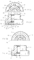
- the hollow body element 10 consists of an essentially cylindrical body made of metal, with an end face 12 which, after the element has been attached to a plate-shaped component, faces it.
- the end face 12 has an annular recess 14 which is arranged within a raised annular contact surface 16, the bottom surface 18 of the annular recess extending as far as the bore 20 of the hollow body element 10.
- the bore 20 has a central axis 22, which also represents the longitudinal axis of the hollow body element, and is designed here as a threaded bore with a thread 24, so that the hollow body element shown here is a nut element.
- the bottom surface 18 of the annular recess 14 passes over an annular shoulder 26 into an annular surface 28 with the outer diameter of the annular surface 28 being slightly larger than the outer diameter D of the thread 24 provided in the bore 20. It can be seen that the bore 20 or the thread 24, the annular surface 28, the annular shoulder 26 and the annular recess 14 and also the contact surface 12 are coaxial with the central axis 22 of the hollow body element 10.
- the further end face 30 of the hollow body element is flat in this example and only provided with a small recess 32 which forms a clean transition to the thread 24.
- the stepped lateral surface 34 of the hollow body element merges into the end face 12 over a small radius 36, this radius 36 preferably being smaller than 0.5 mm, for example 0.3 mm.
- depressions 38 are provided in the annular contact surface, which, as can be seen in FIG. 2, are approximately wedge-shaped and theirs have greatest depth at the transition into the side wall 15 of the annular recess 14.
- the depressions 38 are approximately rectangular, as can be seen in FIG. 1. These depressions are produced during the cold hammering during the production of the nut element and the corresponding deformation of the hollow body blank leads to bead-like projections 40 in the side wall of the annular depression 14, these projections, as can be clearly seen on the left-hand side of FIG. 2, leading to local undercuts 41 in FIG Guide the side wall of the annular recess 14.
- Suitable materials for the hollow body elements are all materials that reach the strength values of class 8 according to the Isostandard during cold forming, for example a 35 B2 alloy according to DIN 1654.
- the hollow body elements or nut elements formed in this way are suitable for all commercially available steel materials ductile sheet metal parts as well as for aluminum or magnesium or their alloys.
- the nuts can also be formed in other materials, for example in an aluminum alloy, in particular in an aluminum alloy of higher strength.
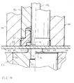
- FIG. 3 shows the hollow body element 10 according to the invention in a setting head 44 which is only partially shown and which has a stamp 46 and a stamp arranged coaxially to the stamp 46 Has punch 48.
- a setting head of this type is known in principle from the above-mentioned German publications, ie DE-PS 34 46 978 and DE-OS 38 35 556.3.
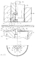
- a die 50 which, as shown in FIG. 7A, is inserted, for example, as a cylindrical component in a cylindrical bore 51 of a lower tool 52 of a press and at the correct height flush with the surface of the lower tool 52 by means of a Spacer 54 is held.
- the die 50 has a central bore 56 which merges into a larger bore 60 via an annular shoulder 58.
- the front end 62 of the die 50 has a flat surface 64 which lies flush with the surface 66 of the lower tool 52.
- the end face of the die 50 has a shaped hole shoulder 68.
- the bore 56 which forms the hole in the shaped hole shoulder 68, has an annular cutting edge 70 which has an inner diameter which corresponds to that of the bore in the hollow body element.
- the end face 72 which is arranged coaxially to the longitudinal axis 22 and which is at least substantially perpendicular to this axis, has a rounded drawing edge 74 at the transition to the lateral surface of the shaped hole heel 68.
- a plurality of lugs 76 are arranged around the shaped hole at intervals, six six such lugs being provided in this example, which are evenly arranged around the shaped hole shoulder 68.
- the lugs 76 have an inclined surface 78 and are raised both on the outer surface of the shaped hole heel 68 and on the flat end surface 64 of the die 50.
- the lugs 76 which are rounded on all surfaces, are somewhat narrower than the depressions 38 in the annular contact surface 16 of the nut element 10.
- the setting head 44 itself is arranged in a manner known per se on the upper tool of a press and, in the usual manner, is designed in such a way that the respective nut elements 10 enter the bore 80 of the setting head 44 via an oblique channel and then by means of the stamp 46 can be felt up to the front end of the setting head when the press is closed.
- the mother elements can also be held during this movement, for which devices are known, for example from the PCT application with the publication number WO 93/19890.
- the setting head moves from the position in FIG. 3 to the position in FIG. 4.
- the lower end 77 of the setting head 44 succeeds in this way in contact with the sheet metal part 42 and this is in turn pressed against the end face 72 of the die 50.
- a further downward movement of the housing 79 of the setting head is prevented at this stage, the housing 79 of the setting head moves back slightly compared to the downward moving tool of the press.
- the upper tool of the press drives but the punch further down first into the position according to FIG. 5.
- a punch 82 is cut from the sheet metal part 42 by the punch 48 in cooperation with the cutting edge 70 of the shaped hole heel 68 of the die 50, as in the following drawing of FIG. 5 is shown.
- a punched hole 83 is created in the sheet metal part 42. From this drawing, one notices that the punch 48 is slidably received in the bore 56 of the die 50 as well as in the bore 20 of the hollow body element 10.
- the slug 82 can be disposed of through the bore 60 of the die 50, the large diameter of this bore 60 compared to the bore 56 ensuring that the slug moves easily under gravity and does not get caught.
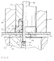
- the housing 79 of the setting head 44 and the punch 46 are moved further downward together, as a result of which the shaped-hole heel 68 or more precisely the rounded pulling edge 74 of the shaped-hole heel has a collar 75 made of the sheet metal material formed around the punch hole 83 to widen the punch hole.
- This deformation continues until the final stage as shown in FIG. 7, and it can be seen from FIG. 7 that the shaped-hole heel 68 has deformed the sheet metal material or the collar 75 in such a way that they form-fit in the annular recess 14 of the hollow body element and is pressed into the undercuts 40.
- the press opens again and the workpiece 42 with the attached hollow body element is ejected from the press or removed from the press and then presents itself as shown in FIG. 8.
- the inner diameter of the collar 75 of the sheet metal part 42 is slightly larger than the outer diameter of the thread 24, so that the sheet metal part cannot prevent the insertion of a bolt.
- the bolt fitting into the thread 24 is usually inserted in the direction of arrow 86 in FIG. 8 and is usually used to fasten a second sheet metal part to the sheet metal part 42. From Fig. 8 it is clear that there is a considerable annular contact surface, so that the surface pressure can be easily kept within permissible limits dependent on the material, even with a hollow body element with a comparatively small diameter.
- the depressions 88 produced by the lugs 76 in the sheet metal part can also be seen in FIG. 8.
- hollow body elements shown here all have a circular-cylindrical outer surface, ie have a circular cross-section in plan view, other cross-sectional shapes, for example polygonal ones, can also be used or oval or grooved cross-sectional shapes are used.
- the expression ring-shaped is also understood to mean not only circular rings, but also ring shapes somewhat different from a circular ring shape, such as a polygon.
- the side wall 41 of the annular recess 14 can also be represented as a polygon or a multi-sided figure.
- annular projection 100 in the bottom region of the annular recess 14.
- This annular projection is not to be regarded as a pilot part, since it only enables the use of a reduced thread or a shortening of the height of the hollow body element, but otherwise no function Has.
- this projection 100 with lugs and / or depressions, an additional anti-rotation device being achievable when the sheet metal part is deformed against the lugs and / or depressions.
- Such an embodiment with lugs 102 and indentations 104 can be seen in FIG. 12, the undercut not being the result of the formation of local indentations such as 38 in FIG.
- the annular contact surface 16 is provided with an annular recess 108 which, for example, has a semicircular cross section and is pressed in at several circumferential locations in order to form bead-like projections 40, as in the embodiment of FIG. 1.
- the die should have a corresponding profiling, so that the sheet metal part lies flush against the entire contact surface.
- the annular recess 108 can also be formed in the manner shown in FIG. H. viewed as a corrugated annular recess in plan view. If the die has a shape that is complementary to this, the required anti-rotation is ensured by this annular recess.
- This annular recess can also be designed so that the inner side wall of the annular recess 14 receives projections 40, which also form undercuts which serve to generate the required squeezing resistance and also offer additional security against rotation.
- a particular advantage of the hollow body element according to the invention is that a hollow body element with sheets of different thicknesses can be used, for example sheets in the range from 0.75 mm to 2.25 mm. It is only necessary to use the appropriate die, whereby the thimble hole should have a larger diameter in the case of thinner sheets than in the case of thicker sheets.
- the hollow body element can be a hollow body which is only provided with a thread after it has been attached to a sheet metal part, for example by a self-tapping screw.
Abstract
Description
Die vorliegende Erfindung betrifft ein Hohlkörperelement nach dem Oberbegriff von Anspruch 1, eine Matrize zur Anwendung mit einem Hohlkörperelement nach dem Oberbegriff des Anspruches 7, ein Verfahren zur Anbringung des Hohlkörperelementes an ein plattenförmiges Bauteil nach dem Oberbegriff des Anspruches 8 und das sich nach Durchführung des Verfahrens ergebende Zusammenbauteil nach dem Oberbegriff des Anspruches 9.The present invention relates to a hollow body element according to the preamble of
Ein Hohlkörperelement nach dem Oberbegriff des Anspruches 1 ist aus der EP-A-0 553 822 A1 bzw. aus der entsprechenden US-A-5 340 251 und aus der späteren noch nicht veröffentlichten europäischen Patentanmeldung Nr. 95 102 794.5 bekannt. Ähnliche Hohlkörperelemente sind außerdem aus der US-A-3 234 987, der US-A-3 648 747 oder der US-A-3 253 631 bekannt.A hollow body element according to the preamble of
Alle diese bekannten Ausführungsformen haben ein sogenanntes Pilotteil, das heißt, daß die ringförmige Vertiefung an der dem Bauteil zugewandten Stirnfläche auf der radial inneren Seite durch einen vorstehenden sich ebenfalls zumindest im wesentlichen bis zu der Stirnfläche vorragenden zylinderförmigen Pilotteil begrenzt ist.All of these known embodiments have a so-called pilot part, that is to say that the annular recess on the end face facing the component is delimited on the radially inner side by a projecting cylindrical pilot part which also projects at least essentially up to the end face.
Solche Hohlkörperelemente die im Regelfall als Mutterelemente ausgebildet werden, die aber auch beispielsweise eine einfache Zylinderbohrung zur Aufnahme eines Zapfens oder dergleichen aufweisen konnten, bieten eine verhältnismäßig hohe Verdrehsicherheit, so daß beim Einschrauben eines Bolzenelementes die Hohlkörperelemente fest an dem Bauteil verankert bleiben, und darüber hinaus einen relativ hohen Auspresswiderstand.Such hollow body elements, which are generally designed as nut elements, but which could also have, for example, a simple cylinder bore for receiving a pin or the like, offer a relatively high degree of security against rotation, so that when a bolt element is screwed in, the hollow body elements remain firmly anchored to the component, and moreover a relatively high squeezing resistance.
Es hat sich aber herausgestellt, daß im Betrieb unter Wechselbelastungen die Elemente manchmal aus dem plattenförmigen Bauteil (üblicherweise ein Blech) herausreißen. Auch ist die Herstellung solcher Hohlkörperelemente relativ aufwendig und es liegt ein Problem, der Gestalt vor, daß die Anlagefläche häufig nicht ausreichend ist und des weiteren, daß die radialen Abmessungen der eingebauten Elemente die Verwendung einer relativ großen Scheibe auf der Bolzenseite erforderlich machen um die Kräfte in der erwünschten Weise zu übertragen.However, it has been found that the elements sometimes tear out of the plate-shaped component (usually a sheet) during operation under alternating loads. Also, the manufacture of such hollow body elements is relatively complex and there is a problem, the shape that the contact surface is often not sufficient and further that the radial dimensions of the installed elements require the use of a relatively large washer on the bolt side to the forces to transmit in the desired manner.
Die Hinterschneidung in der Seitenwand der ringförmigen Vertiefung, welche zur Erzeugung des geforderten Auspresswiderstandes des Hohlkörpers erforderlich ist, wird üblicherweise dadurch erzeugt, daß das Hohlkörperelement einem Quetschvorgang am umlaufenden Außenmantel unterzogen wird, wodurch die Seitenwand der ringförmigen Vertiefung von einer zunächst axial parallelen Lage in eine Schräglage gebracht wird wodurch die Öffnung zu der ringförmigen Vertiefung zwischen dem Pilotteil und der jetzt geneigten Seitenwand im Vergleich zu der Bodenfläche der Vertiefung verkleinert wird. Durch diese Quetschbewegung weist das Hohlkörperelement aber auch eine Schrägfläche an der äußeren Mantelfläche benachbart zu der dem Bauteil zugewandten Stirnfläche auf. Bei der Anbringung an das plattenförmige Bauteil wird die dem plattenförmigen Bauteil zugewandte keilförmige Auflagefläche häufig so verformt, daß sie unter Belastung messerartig wirkt und sich eine hohe Flächenpressung zwischen dem Bauteil und dem Hohlkörperelement ergibt.The undercut in the side wall of the annular recess, which is required to generate the required squeezing resistance of the hollow body, is usually produced by subjecting the hollow body element to a squeezing process on the circumferential outer jacket, as a result of which the side wall of the annular recess moves from an initially axially parallel position into one Is inclined, whereby the opening to the annular recess between the pilot part and the now inclined side wall is reduced compared to the bottom surface of the recess. As a result of this squeezing movement, the hollow body element also has an inclined surface on the outer circumferential surface adjacent to the end face facing the component. When attached to the plate-shaped component, the wedge-shaped bearing surface facing the plate-shaped component is often deformed in such a way that it acts knife-like under load and there is a high surface pressure between the component and the hollow body element.
Aufgrund dieser hohen Flächenpressung gibt das plattenförmige Bauteil nach wenigen Betriebsstunden nach und sitzt nicht mehr so fest wie erwünscht, so daß die Gefahr des Setzens und,, des Reduzierens der Vorspannkraft auf Null zu und damit das Versagen von der Schraubverbindung besteht.Due to this high surface pressure, the plate-shaped component gives way after a few hours of operation and is no longer as tight as desired, so that there is a risk of setting and reducing the pretensioning force to zero and thus the failure of the screw connection.
Der vorliegenden Erfindung liegt die Aufgabe zugrunde hier Abhilfe zu schaffen und ein Hohlkörperelement, insbesondere ein Mutterlement vorzusehen, das einerseits preisgünstig herstellbar ist andererseits aber nicht nur eine gute Verdrehsicherung und einen festen Sitz nach seiner Anringung an das plattenförmige Bauteil sicherstellt, sondern darüber hinaus auch bei Wechselbelastung den festen Sitz beibehält ohne aus dem plattenförmigen Bauteil herausgerissen zu werden und ohne daß eine Lockerung des verwendeten Bolzenelementes zu befürchten ist, wobei die ringförmige Auflagefläche im Vergleich zu den bisherigen Lösungen im Durchmesser kleiner werden jedoch flächenmäßig ausreichend groß sein soll, damit eine unerwünscht hohe Flächenpressung am plattenförmigen Bauteil nicht auftritt.The present invention has for its object to remedy this situation and to provide a hollow body element, in particular a mother element, which on the one hand is inexpensive to produce and on the other hand not only ensures good torsion protection and a firm fit after being attached to the plate-shaped component, but also also Alternating load maintains the tight fit without being torn out of the plate-shaped component and without fear of loosening of the bolt element used, the ring-shaped contact surface being smaller in diameter compared to previous solutions, however, should be sufficiently large in area so that an undesirably high one Surface pressure does not occur on the plate-shaped component.
Zur Lösung dieser Aufgabe wird erfindungsgemäß vorgesehen, daß die Bodenfläche der ringförmigen Vertiefung zumindest im wesentlichen ohne ein Pilotteil sich bis zum Durchgang der Bohrung erstreckt.To achieve this object it is provided according to the invention that the bottom surface of the annular recess extends at least substantially without a pilot part to the passage of the bore.
Das Pilotteil, das bei den bisher erwähnten Mutterelementen eine zentrale Rolle bei der Umformung des plattenförmigen Bauteils in die ringförmige Vertiefung spielte, wird somit jetzt fortgelassen, so daß die radialen Abmessungen des Mutterelementes in etwa um die Wanddickenabmessungen der üblichen Pilotteile reduziert werden können, wodurch der Innendurchmesser der ringförmigen Anlagefläche wesentlich kleiner wird. Dies bietet aber auch die Möglichkeit den äußeren Durchmesser der ringförmigen Anlagefläche im Vergleich zu dem Innendurchmesser so zu gestalten, daß die radiale Breite der ringförmigen Anlagefläche größer wird, wodurch insgesamt eine im Vergleich zu den bekannten Hohlkörperelementen vergrößerte Ringfläche vorliegt und hierdurch im Betrieb die Flächenpressung herabgesetzt werden kann.The pilot part, which played a central role in the shaping of the plate-shaped component into the annular recess in the previously mentioned nut elements, is now omitted, so that the radial dimensions of the nut element can be reduced approximately by the wall thickness dimensions of the conventional pilot parts, whereby the Inner diameter of the annular contact surface becomes significantly smaller. However, this also offers the possibility of designing the outer diameter of the annular contact surface in comparison to the inner diameter in such a way that the radial width of the annular contact surface becomes larger, as a result of which there is an overall enlarged annular surface in comparison with the known hollow body elements and thereby the surface pressure is reduced during operation can be.
Aufgrund der geänderten Abmessungen kann auch die Notwendigkeit zur Verwendung einer Scheibe auf der Bolzenseite entfallen.Due to the changed dimensions, there is also no need to use a washer on the bolt side.
Um dieses Hohlkörperelement zu verwenden, ist eine Modifikation der Matrize und des Setzkopfes notwendig um die bisher vom Pilotteil erfüllten Funktionen auf andere Art und Weise zu erbringen.In order to use this hollow body element, a modification of the die and the setting head is necessary in order to perform the functions previously performed by the pilot part in a different way.
Beim Stand der Technik diente das Pilotteil einerseits als Lochstanze um bei der Anbringung des Hohlkörperelementes an einem Blechteil in Zusammenarbeit mit einer Matrize einen Butzen aus dem Blechteil herauszustanzen. Diese Stanzfunktion wird nunmehr mittels eines im Setzkopf koaxial zum Hohlkörperelement geführten Lochstempels erreicht der bei der Schließbewegung des Setzkopfes sich durch die Bohrung des Hohlkörperelementes hindurchbewegt und in Zusammenarbeit mit der Matrize für die Ausstanzung des Butzens sorgt.In the prior art, the pilot part served on the one hand as a punch to punch a slug out of the sheet metal part when the hollow body element was attached to a sheet metal part in cooperation with a die. This punching function is now achieved by means of a punch which is guided coaxially to the hollow body element in the setting head and which moves through the bore of the hollow body element during the closing movement of the setting head and, in cooperation with the die, ensures that the slug is punched out.
Ein solcher Lochstempel ist zwar bekannt, beispielsweise aus dem deutschen Patent 34 46 978, oder aus der DE-OS 38 35 566.3, jedoch wird der Lochstempel hier mit einem anders gestalteten Hohlkörperelement verwendet das sozusagen auch ein Pilotteil aufweist in Form eines sogenannten Nietabschnittes. Somit liegt die Anwendung eines Lochstempels mit einem Mutterelement ohne Pilotteil nicht nah.Such a punch is known, for example from
Eine andere Funktion des Pilottells bei den Hohlkörperelementen nach dem eingangs genannten Stand der Technik lag darin das Metall des Bleches in die Hinterschneidung hinein zu formen um hierdurch die Sicherheit gegen Auspressung und zusätzlich auch die Verdrehsicherheit zu erzeugen. Auch diese Funktion wird nach der vorliegenden Erfindung von der Matrize übernommen und anders als bisher gelöst.Another function of the pilot plate in the case of the hollow body elements according to the prior art mentioned at the outset was to shape the metal of the sheet metal into the undercut in order to thereby produce security against being squeezed out and additionally also security against rotation. According to the present invention, this function is also taken over by the die and solved differently than previously.
Zur Erzeugung der Verdrehsicherung bei dem erfindungsgemäßen Hohlkörperelement werden in der ringförmigen Anlagefläche eine Anzahl von Vertiefungen eingepreßt. Die Matrize für das Einsetzen des Mutterlementes weist mehrere Nasen auf die sicherstellen, daß das Material des plattenförmigen Bauteils in mindestens eine der Vertiefungen und vorzugsweise in mehrere der Vertiefungen hineingepreßt wird und hierdurch eine Verdrehsicherung erzeugt. Es können beispielsweise acht Vertiefungen in der ringförmigen Anlagefläche vorgesehen werden und sechs Nahen auf der Matrize, wodurch unabhängig von der jeweiligen Rotationsstellung des Hohlkörpers mindestens eine der Nasen einer Vertiefung gegenüberliegt.To generate the anti-rotation device in the hollow body element according to the invention, a number of depressions are pressed into the annular contact surface. The die for the insertion of the nut element has a plurality of lugs which ensure that the material of the plate-shaped component is pressed into at least one of the depressions and preferably into several of the depressions and thereby produces an anti-rotation device. For example, eight depressions can be provided in the ring-shaped contact surface and six seams on the die, as a result of which at least one of the lugs is opposite a depression, regardless of the respective rotational position of the hollow body.
Durch die Verwendung von Vertiefungen in der ringförmigen Auflagefläche wird während des Einpresens der Vertiefungen Hinterschneidungen an der Seitenwand der ringförmig Vertiefung im Hohlkörperelement gleichzeitig erzeugt und zwar in Form von lokalen wulstartigen Verformungen der Seitenwand.By using depressions in the annular contact surface, undercuts on the side wall of the annular depression in the hollow body element are simultaneously produced during the pressing of the depressions, specifically in the form of local bead-like deformations of the side wall.
Bei dem Fügevorgang wird das Blech in die so gebildeten Hinterschneidungen gepreßt, was einerseits den erforderlichen Auspresswiderstand sicherstellt andererseits aber auch eine zusätzliche Verdrehsicherung bildet.During the joining process, the sheet metal is pressed into the undercuts formed in this way, which on the one hand ensures the required squeezing resistance but on the other hand also forms an additional anti-rotation device.
Dadurch, daß die Hinterschneidungen während der Einbringung der Vertiefungen in der ringförmigen Anlagefläche des Hohlkörperelementes entstehen und nicht durch eine Quetschbewegung an der Mantelfläche des Hohlkörperelementes erzeugt werden müssen, fehlt bei dem Hohlkörperelement die ausgeprägte Fase die bei Hohlkörperelementen nach der eingangs genannten EP-A-0 553 822 oder nach der europäischen Patentanmeldung 95 102 794.5 entstehen. Dies ist aber von Vorteil, da es dann möglich ist, der Übergang von der ringförmigen Anlagefläche in die Mantelfläche des Hohlkörperelementes mit lediglich einem kleinen Radius beispielsweise unter 0,5 mm auszubilden, wodurch die verfügbare Fläche der ringförmigen Auflagefläche im Vergleich zum Stand der Technik erhöht werden kann.Due to the fact that the undercuts occur during the introduction of the depressions in the annular contact surface of the hollow body element and do not have to be produced by a squeezing movement on the outer surface of the hollow body element, the hollow body element lacks the pronounced chamfer that is found in hollow body elements according to the aforementioned EP-A-0 553 822 or according to European patent application 95 102 794.5. However, this is advantageous since it is then possible to design the transition from the annular contact surface into the lateral surface of the hollow body element with only a small radius, for example less than 0.5 mm, whereby the available area of the annular contact surface can be increased compared to the prior art.
Weitere bevorzugte Ausführungsformen des Anmeldungsgegenstandes sind den weiteren Unteransprüchen zu entnehmen. Die erfindungsgemäße Matrize zur Anwendung mit dem Hohlkörperelement ist im Anspruch 7 des Verfahrens zur Anbringung des Hohlkörperelementes an ein plattenförmiges Bauteil im Anspruch 8 angegegeben. Das sich hierdurch ergebende Zusammenbauteil ist dem Anspruch 9 zu entnehmen.Further preferred embodiments of the subject of the application can be found in the further subclaims. The die according to the invention for use with the hollow body element is specified in claim 7 of the method for attaching the hollow body element to a plate-shaped component. The resulting assembly part can be found in claim 9.
Die Erfindung wird nachfolgend anhand von Ausführungsbeispielen unter Bezugnahme auf die Zeichnung näher erläutert, in welchen zeigen:
- Fig. 1
- eine Draufsicht auf der Stirnseite eines erfindungsgemäßen Hohlkörperelementes, wobei der Einfachheit halber lediglich die Hälfte des Hohlkörperelementes gezeigt wird,
- Fig. 2
- eine teilweise geschnittene Seitenansicht der erfindungsgemäßen Hohlkörperelementes der Fig. 1,
- Fig. 3
- eine schematische Darstellung der ersten Phase eines erfindunsgemäßen Verfahrens zur Anbringung des Hohlkörperelementes nach Fig. 1 und 2 an ein plattenförmiges Bauteil,
- Fig. 4
- eine spätere Phase des erfindungsgemäßen Verfahrens kurz vor der Lochung des plattenförmigen Bauteiles,
- Fig. 5
- eine spätere Phase des erfindungsgemäßen Verfahrens gerade nach der Lochung des plattenförmigen Bauteiles,
- Fig. 6
- eine noch spätere Phase des erfindungsgemäßen Verfahrens bei der Umformung des plattenförmigen Bauteiles,
- Fig. 7, 7A
- das Ende des erfindungsgemäßen Verfahrens nach der Anbringung des Hohlkörperelementes an das plattenförmige Bauteil, wobei die Fig. 7A die Anordnung der Matrize im unteren Werkzeug zeigt,
- Fig. 8
- eine teilweise geschnittene Seitenansicht des Zusammenbauteils bestehend aus dem erfindungsgemäßen Hohlkörperelement und einem Blechteil,
- Fig. 9
- eine etwas abgewandelte Ausführungsform des Hohlkörperelementes der Fig. 1 in einer Darstellung entsprechend der Fig. 2,
- Fig. 10
- eine weitere mögliche Abwandlung des Hohlkörperelementes der Fig. 1 ebenfalls in einer Darstellung entsprechend der Fig. 2,
- Fig. 11
- eine Draufsicht auf der Anlagefläche des Hohlkörperelementes der Fig. 10 und
- Fig. 12
- eine weitere Darstellung einer möglichen Ausführungsvariante des Hohlkörperelementes in der Fig. 1 wiederum in eine Darstellung entsprechend der Fig. 2.
- Fig. 1
- 3 shows a plan view of the end face of a hollow body element according to the invention, only half of the hollow body element being shown for the sake of simplicity,
- Fig. 2
- 2 shows a partially sectioned side view of the hollow body element according to the invention from FIG. 1,
- Fig. 3
- 2 shows a schematic representation of the first phase of a method according to the invention for attaching the hollow body element according to FIGS. 1 and 2 to a plate-shaped component,
- Fig. 4
- a later phase of the method according to the invention shortly before the perforation of the plate-shaped component,
- Fig. 5
- a later phase of the method according to the invention just after the perforation of the plate-shaped component,
- Fig. 6
- an even later phase of the method according to the invention in the forming of the plate-shaped component,
- 7, 7A
- the end of the method according to the invention after the attachment of the hollow body element to the plate-shaped component, FIG. 7A showing the arrangement of the die in the lower tool,
- Fig. 8
- 2 shows a partially sectioned side view of the assembly part consisting of the hollow body element according to the invention and a sheet metal part,
- Fig. 9
- 1 shows a somewhat modified embodiment of the hollow body element of FIG. 1 in a representation corresponding to FIG. 2,
- Fig. 10
- another possible modification of the hollow body element of FIG. 1 also in a representation corresponding to FIG. 2,
- Fig. 11
- a plan view of the contact surface of the hollow body element of FIGS. 10 and
- Fig. 12
- a further representation of a possible embodiment variant of the hollow body element in FIG. 1 again in a representation corresponding to FIG. 2.
Nach den Fig. 1 und 2 besteht das Hohlkörperelement 10 aus einem im wesentlichen zylinderförmigen Körper aus Metall, mit einer Stirnfläche 12 welche nach der Anbringung des Elementes an einem plattenförmigen Bauteil diesem zugewandt ist. Die Stirnfläche 12 weist eine ringförmige Vertiefung 14 auf welche innerhalb einer erhabenen ringförmigen Anlagefläche 16 angeordnet ist, wobei die Bodenfläche 18 der ringförmigen Vertiefung sich bis zu der Bohrung 20 des Hohlkörperelementes 10 erstreckt. Die Bohrung 20 weist eine mittlere Achse 22 die zugleich die Längsachse des Hohlkörperelementes darstellt, auf und ist hier als eine Gewindebohrung mit Gewinde 24 ausgebildet, so daß das hier gezeigte Hohlkörperelement ein Mutterelement ist.1 and 2, the
Die Bodenfläche 18 der ringförmigen Vertiefung 14 geht über eine Ringschulter 26 in eine Ringfläche 28 über wobei der Außendurchmesser der Ringfläche 28 geringfügig größer ist als der Außendurchmesser D des in der Bohrung 20 vorgesehenen Gewindes 24. Man merkt, daß die Bohrung 20 bzw. das Gewinde 24, die Ringläche 28, die Ringschulter 26 und die ringförmige Vertiefung 14 sowie auch die Anlagefläche 12 koaxial zur mittleren Achse 22 des Hohlkörperelementes 10 liegen. Die weitere Stirnfläche 30 des Hohlkörperelementes ist in diesem Beispiel flach ausgebildet und lediglich mit einer kleinen Versenkung 32 versehen, welche einen sauberen Übergang zum Gewinde 24 bildet.The
Die abgestuft ausgebildete Mantelfläche 34 des Hohlkörperelementes geht über einen kleinen Radius 36 in die Stirnfläche 12 über, wobei dieser Radius 36 vorzugsweise kleiner als 0,5 mm beispielsweise 0,3 mm ausgeführt ist.The stepped
In der ringförmigen Anlagefläche sind in diesem Beispiel acht Vertiefungen 38 vorgesehen, welche, wie aus der Fig. 2 ersichtlich, in etwa keilförmig ausgestaltet sind und ihre größte Tiefe beim Übergang in die Seitenwand 15 der ringförmigen Vertiefung 14 aufweisen. In Draufsicht sind die Vertiefungen 38 in etwa rechteckig wie aus der Fig. 1 ersichtlich. Diese Vertiefungen werden beim Kaltschlagen während der Herstellung des Mutterelementes erzeugt und die entsprechende Verformung des Hohlkörperrohlings führt zu wulstartigen Vorsprüngen 40 in der Seitenwand der ringförmigen Vertiefung 14 wobei diese Vorsprünge wie auf der linken Seite der Fig. 2 deutlich zu sehen zu lokalen Hinterschneidungen 41 in der Seitenwand der ringförmigen Vertiefung 14 führen.In this example, eight
Als Werkstoffe für die Hohlkörperelemente eignen sich alle Materialien, die im Rahmen der Kaltverformung die Festigkeitswerte der Klasse 8 gemäß Isostandard erreichen, beispielsweise eine 35 B2-Legierung gemäß DIN 1654. Die so gebildeten Hohlkörperelemente bzw. Mutterelemente eignen sich unter anderem für alle handelsüblichen Stahlwerkstoffe für ziehfähige Blechteile wie auch für Aluminium oder Magnesium oder deren Legierungen. Die Muttern können auch in anderen Werkstoffen ausgebildet werden, beispielsweise in einer Aluminiumlegierung, insbesondere in einer Aluminiumlegierung höherer Festigkeit.Suitable materials for the hollow body elements are all materials that reach the strength values of class 8 according to the Isostandard during cold forming, for example a 35 B2 alloy according to DIN 1654. The hollow body elements or nut elements formed in this way are suitable for all commercially available steel materials ductile sheet metal parts as well as for aluminum or magnesium or their alloys. The nuts can also be formed in other materials, for example in an aluminum alloy, in particular in an aluminum alloy of higher strength.
Es versteht sich, daß in der Fig. 2 die Ausbildung des Mutterelementes auf der rechten Seite der mittleren Achse 22 identisch ist wie auf der linken Seite.It is understood that in FIG. 2 the design of the nut element on the right side of the
Die Art der Anbringung des Hohlkörperelementes nach den Fig. 1 und 2 in ein plattenförmiges Bauteil in Form eines Blechteils 42 wird nachfolgend anhand der Fig. 3 bis 8 näher erläutert.The type of attachment of the hollow body element according to FIGS. 1 and 2 in a plate-shaped component in the form of a
In der Fig. 3 wird das erfindungsgemäße Hohlkörperelement 10 in einem nur teilweise dargestellten Setzkopf 44 gezeigt, der einen Stempel 46 sowie einen koaxial zum Stempel 46 angeordneten Lochstempel 48 aufweist. Ein Setzkopf dieser Art ist für sich im Prinzip aus den oben erwähnten deutschen Druckschriften, d.h. DE-PS 34 46 978 und DE-OS 38 35 556.3 bekannt.3 shows the
Unterhalb des Blechteiles 42 befindet sich eine Matrize 50 welche, wie in der Fig. 7A dargestellt beispielsweise als zylindrisches Bauteil in einer zylindrischen Bohrung 51 eines unteren Werkzeuges 52 einer Presse eingesetzt ist und in der richtigen Höhe bündig mit der Oberfläche des unteren Werkzeuges 52 mittels eines Abstandhalters 54 gehalten wird. Die Matrize 50 weist eine mittlere Bohrung 56 auf die über eine Ringschulter 58 in eine größere Bohrung 60 übergeht. Das Stirnende 62 der Matrize 50 weist eine ebene Fläche 64 auf welche bündig mit der Oberfläche 66 des unteren Werkzeuges 52 liegt. Weiterhin weist das Stirnende der Matritze 50 einen Formlochabsatz 68 auf. Die Bohrung 56, welche das Loch des Formlochabsatzes 68 bildet, hat eine ringförmige Schneidkante 70, der einen Innendurchmesser aufweist, der dem der Bohrung des Hohlkörperelementes entspricht. Die zur Längsachse 22 koaxial angeordnete Stirnfläche 72 welche zumindest im wesentlichen senkrecht zu dieser Achse liegt, weist am Übergang zu der Mantelfläche des Formlochabsatzes 68 eine gerundete Ziehkante 74 auf.Beneath the
Um das Formloch in Abständen herum angeordnet befinden sich mehrere Nasen 76, wobei in diesem Beispiel sechs solcher Nasen vorgesehen sind, die gleichmäßig um den Formlochabsatz 68 herum angeordnet sind. Die Nasen 76 haben eine Schrägfläche 78 und sind sowohl an der Mantelfläche des Formlochabsatzes 68 wie auch der ebenen Stirnfläche 64 der Matrize 50 erhaben ausgebildet.A plurality of
Die Nasen 76, die insgesamt an allen Flächen gerundet sind, sind etwas schmäler ausgebildet als die Vertiefungen 38 in der ringförmigen Anlagefläche 16 des Mutterelementes 10. Durch die Verwendung der gleichen Bezugszeichen 22 wird deutlich gemacht, daß der Lochstempel 48, der Stempel 46, die untere Stirnfläche 77 des Setzkopfes, das Hohlelement 10 und die Matrize 50 des unteren Werkzeuges 52 wie auch die Bohrung 56 und die Bohrung 60 der Matrize und schließlich auch der Durchgangsbohrung des Abstandshalters 54 alle koaxial angeordnet sind.The
Der Setzkopf 44 selbst ist in an sich bekannter Weise an dem oberen Werkzeug einer Presse angeordnet und wird, in der üblichen Art und Weise so ausgestaltet, daß die jeweiligen Mutterelemente 10 über einen Schrägkanal in die Bohrung 80 des Setzkopfes 44 gelangen und anschließend mittels des Stempels 46 beim Schließen der Presse bis zu dem Stirnende des Setzkopfes gefühlt werden. Die Mutterelemente können auch während dieser Bewegung gehalten werden wofür Vorrichtungen bekannt sind, beispielsweise aus der PCT-Anmeldung mit der Veröffentlichungsnummer WO 93/19890.The setting
Beim Schließen der Presse, beispielsweise zur Formgebung des Blechteils durch das untere Werkzeug 52 in Kombination mit einem oberen nicht gezeigten Werkzeug, bewegt sich der Setzkopf aus der Stellung der Fig. 3 in die Stellung nach Fig. 4. Das untere Stirnende 77 des Setzkopfes 44 gelingt auf diese Weise in Anlage an das Blechteil 42 und dieses wird wiederum gegen die Stirnfläche 72 der Matrize 50 gepreßt. Eine weitergehende Bewegung des Gehäuses 79 des Setzkopfes nach unten wird in diesem Stadium verhindert, das Gehäuse 79 des Setzkopfes weicht gegenüber dem nach unten sich bewegenden Werkzeug der Presse etwas zurück. Dies gilt auch für den Stempel 46, der vorteilhafterweise gegen die Ringschulter 35 des Hohlkörperelementes drückt und nicht gegen die Stirnfläche 31, wodurch die Gefahr der Beschädigung des Gewindes 34 wirksam vermieden wird. Das obere Werkzeug der Presse treibt aber den Lochstempel weiter nach unten zunächst in die Stellung nach der Fig. 5. Dabei wird vom Lochstempel 48 in Zusammenarbeit mit der Schneidkante 70 des Formlochabsatzes 68 der Matrize 50 ein Butzen 82 aus dem Blechteil 42 geschnitten, wie in der Folgezeichnung der Fig. 5 dargestellt ist. Auf diese Weise entsteht ein Stanzloch 83 im Blechteil 42. Aus dieser Zeichnung merkt man, daß der Lochstempel 48 gleitend in die Bohrung 56 der Matrize 50 wie auch in der Bohrung 20 des Hohlkörperelementes 10 aufgenommen wird.When the press is closed, for example for shaping the sheet metal part by the
Der Butzen 82 kann durch die Bohrung 60 der Matrize 50 entsorgt werden, wobei der große Durchmesser dieser Bohrung 60 im Vergleich zu der Bohrung 56 dafür sorgt, daß der Butzen sich unter Schwerkraft leicht bewegt und nicht hängenbleibt.The
Bei der weiteren Schließbewegung der Presse wird, wie in Fig. 6 gezeigt auch das Gehäuse 79 des Setzkopfes 44 und der Stempel 46 gemeinsam weiter nach unten bewegt, wodurch der Formlochabsatz 68 oder genauer gesagt die gerundete Ziehkante 74 des Formlochabsatzes einen Kragen 75 aus dem Blechwerkstoff um das Stanzloch 83 herum unter Aufweitung des Stanzloches ausbildet. Diese Verformung setzt sich bis zum Endstadium wie in der Fig. 7 gezeigt, fort und man sieht aus der Fig. 7 das der Formlochabsatz 68 das Blechmaterial bzw. den Kragen 75 so verformt hat, daß diese formschlüssig in der ringförmigen Vertiefung 14 des Hohlkörperelementes und in den Hinterschneidungen 40 hineingepreßt wird.During the further closing movement of the press, as shown in FIG. 6, the
Durch die unterschiedliche Zahl der Nasen 46, im Vergleich zu der Zahl der Vertiefungen 38 in der ringförmigen Anlagefläche 16 des Hohlkörperelementes wird sichergestellt, daß mindestens eine Nase vollständig mit einer Vertiefung 38 zur Deckung kommt und zwar ohne daß Maßnahmen getroffen werden müssen, um die Drehposition des Hohlkörperelementes um die mittlere Achse 22 herum sicherzustellen. Auch bei anderen Vertiefungen 38 kann mit einer zumindest teilweisen Deckung mit Nasen der Matrize gerechnet werden, so daß auch hier eine formschlüssige Anlage erfolgt, wodurch die Verdrehsicherung sichergestellt ist.The different number of
Nachdem die wulstartigen Vorsprünge 40, welche die Hinterschneidungen bilden, ebenfalls zu einer gewellten Oberfläche der Seitenwand der ringförmigen Vertiefung 14 führen liefert die formschlüssige Anlage des Blechteils an dieser Seitenwand ebenfalls einen bedeutenden Beitrag zu der Verdrehsicherheit der Verbindung.After the bead-
Nach dem Verfahrensstand gemäß Fig. 7 öffnet sich die Presse wieder und das Werkstück 42 mit dem angebrachten Hohlkörperelement wird aus der Presse ausgestoßen bzw. aus der Presse entnommen und stellt sich dann so wie in Fig. 8 dargestellt dar. Man sieht aus der Fig. 8, daß der Innendurchmesser des Kragens 75 des Blechteiles 42 etwas größer ist als der Außendurchmesser des Gewindes 24, so daß das Blechteil die Einführung eines Bolzens nicht verhindern kann. Der in das Gewinde 24 passende Bolzen wird üblicherweise in Pfeilrichtung 86 der Fig. 8 eingeführt und dient üblicherweise dazu, ein zweites Blechteil an dem Blechteil 42 zu befestigen. Aus der Fig. 8 ist deutlich, daß eine beträchtliche ringförmige Anlagefläche vorliegt, so daß die Flächenpressung innerhalb von zulässigen vom Werkstoff abhängigen Grenzen ohne weiteres gehalten werden kann, und zwar auch bei einem Hohlkörperelement mit einem vergleichsweise kleinem Durchmesser. Die durch die Nasen 76 im Blechteil erzeugten Vertiefungen 88 sind auch in der Fig. 8 ersichtlich.7, the press opens again and the
Obwohl die hier gezeigten Hohlkörperelemente alle eine kreiszylindrische Mantelfläche aufweisen, d. h. in Draufsicht einen kreisförmigen Querschnitt aufweisen, können durchaus auch andere Querschnittsformen, beispielsweise polygonalen oder ovalen oder Nuten aufweisenden Querschnittsformen zur Anwendung gelangen. Auch wird der Ausdruck ringförmig so verstanden, daß dies nicht nur Kreisringe, sondern auch von einer Kreisringform etwas abweichende Ringformen, wie beispielsweise ein Polygon umfaßt.Although the hollow body elements shown here all have a circular-cylindrical outer surface, ie have a circular cross-section in plan view, other cross-sectional shapes, for example polygonal ones, can also be used or oval or grooved cross-sectional shapes are used. The expression ring-shaped is also understood to mean not only circular rings, but also ring shapes somewhat different from a circular ring shape, such as a polygon.
Auch die Seitenwand 41 der ringförmigen Vertiefung 14 kann sich als Polygon oder mehrseitige Figur darstellen.The
Es sind verschiedene Ausführungsvarianten der Erfindung vorstellbar, von denen einige anhand der weiteren Fig. 9 bis 12 näher erläutert werden.Various design variants of the invention are conceivable, some of which are explained in more detail with reference to FIGS. 9 to 12.
Bei der Ausführung gemäß Fig. 9 befindet sich ein ringförmiger Vorsprung 100 im Bodenbereich der ringförmigen Vertiefung 14. Diese ringförmige Vorsprung ist nicht als Pilotteil aufzufassen, da sie lediglich die Verwendung einer verringerten Gewinde bzw. eine Verkürzung der Höhe des Hohlkörperelementes ermöglicht aber sonst keine Funktion hat. Es wäre allerdings denkbar, diesen Vorsprung 100 mit Nasen und/oder Vertiefungen zu versehen, wobei bei Verformung des Blechteils gegen die Nasen und/oder Vertiefungen eine zusätzliche Verdrehsicherung erreichbar wäre. Eine solche Ausbildung mit Nasen 102 und Vertiefungen 104 ist der Fig. 12 zu entnehmen wobei hier die Hinterschneidung nicht durch die Ausbildung von lokalen Vertiefungen wie 38 in Fig. 1 sondern in Form einer insgesamt schräggestellten Seitenwand der ringförmigen Vertiefung 14 vorliegt, welche durch eine konusförmige umlaufende Vertiefung 106 der ringförmigen Anlagefläche erzeugt wird. Da bei der Fig. 12 Ausführung die eine Verdrehsicherung bildenden Vertiefungen 38 fehlen und die Seitenwand sich als geneigte Wand darstellt, bieten die Nasen 102, 104 die einzige Verdrehsicherungsmöglichkeit.In the embodiment according to FIG. 9 there is an
Bei der Ausführung gemäß Fig. 10 ist die ringförmige Anlagefläche 16 mit einer ringförmigen Vertiefung 108 versehen, welche beispielsweise einen halbkreisförmigen Querschnitt aufweist und an mehrere Umfangsstellen eingedrückt wird um auch hier wulstartige Vorsprünge 40 auszubilden, wie bei der Ausführung der Fig. 1. Bei Verwendung einer solchen profillierten Anlagefläche soll die Matrize eine entsprechende Profillierung aufweisen, damit das Blechteil bündig an der gesamten Anlagefläche anliegt.In the embodiment according to FIG. 10, the
Die ringförmige Vertiefung 108 kann auch in der Art und Weise ausgebildet werden, wie in der Fig. 11 gezeigt, d. h. als gewellte ringförmige Vertiefung in Draufsicht betrachtet. Wenn die Matrize eine hierzu komplementäre Form aufweist, wird durch diese ringförmige Vertiefung die erforderliche Verdrehsicherung sichergestellt.The
Diese ringförmige Vertiefung kann auch so ausgeführt werden, daß die innere Seitenwand der ringförmigen Vertiefung 14 Vorsprünge 40 bekommt, die auch Hinterschneidungen bilden die zur Erzeugung des erforderlichen Auspreßwiderstandes dienen und auch eine zusätzliche Verdrehsicherung bieten.This annular recess can also be designed so that the inner side wall of the
Ein besonderer Vorteil des erfindungsgemäßen Hohlkörperelementes liegt darin, daß ein Hohlkörperelement mit Blechen verschiedener Dicken verwendet werden kann beispielsweise Bleche im Bereich von 0,75 mm bis zu 2,25 mm. Es ist lediglich erforderlich, die passende Matrize zu verwenden wobei bei dünneren Blechen der Formlochabsatz einen größeren Durchmesser als bei dickeren Blechen aufweisen muß.A particular advantage of the hollow body element according to the invention is that a hollow body element with sheets of different thicknesses can be used, for example sheets in the range from 0.75 mm to 2.25 mm. It is only necessary to use the appropriate die, whereby the thimble hole should have a larger diameter in the case of thinner sheets than in the case of thicker sheets.
Es kann sich bei dem Hohlkörperelement um einen hohlen Körper handeln, der erst nach seiner Anbringung an ein Blechteil mit einem Gewinde versehen wird, bspw. durch eine selbstfurchende Schraube.The hollow body element can be a hollow body which is only provided with a thread after it has been attached to a sheet metal part, for example by a self-tapping screw.
Claims (10)
dadurch gekennzeichnet,
daß die Bodenfläche (18) der ringförmigen Vertiefung (14) sich bis zur Bohrung (20) des Hohlkörperelementes erstreckt, oder mit anderen Worten zumindest im wesentlichen ohne ein Pilotteil in die Bohrung (20) übergeht.Hollow body element (10), for example nut element for attachment to a plate-shaped component (42), an annular recess (14) being present on an end face (12) of the hollow body element facing the component within a raised annular contact surface (16), at least one undercut (41) in a side wall of the depression (14) and anti-rotation features (38) are provided,
characterized by
that the bottom surface (18) of the annular recess (14) extends to the bore (20) of the hollow body element, or in other words at least essentially without a pilot part in the bore (20).
dadurch gekennzeichnet,
daß zur Verdrehsicherung mehrere, vorzugsweise voneinander beabstandete Vertiefungen (38) in der ringförmigen Anlagefläche (16) vorhanden sind.Hollow body element according to claim 1,
characterized by
that several, preferably spaced apart recesses (38) are present in the annular contact surface (16) to prevent rotation.
dadurch gekennzeichnet,
daß an der Seitenwand der Vertiefung Erhebungen (40) vorgesehen sind, welche die Hinterschneidungen (41) bilden und zwar an Umfangsstellen, welche den Vertiefungen (38) in der ringförmigen Anlagefläche (16) entsprechen.Hollow body element according to claim 1 or 2,
characterized by
that elevations (40) are provided on the side wall of the depression, which form the undercuts (41), specifically at circumferential locations which correspond to the depressions (38) in the annular contact surface (16).
dadurch gekennzeichnet,
daß ein umlaufende Vertiefung (108), insbesondere im Querschnitt etwa halbkreisförmige Vertiefung in der ringförmigen Anlagefläche (16) vorgesehen ist, wobei vorzugsweise die umlaufende Vertiefung (108) in Draufsicht wellenförmig ist.Hollow body element according to one of the preceding claims,
characterized by
that a circumferential recess (108), especially in A cross-section of approximately semicircular depression is provided in the annular contact surface (16), the circumferential depression (108) preferably being undulating in plan view.
dadurch gekennzeichnet,
daß eine ringförmige Erhebung (100) radial innerhalb der ringförmigen Vertiefung (14) an dessen Bodenfläche (18) und konzentrisch zur Bohrung (20) des Hohlkörperelementes (10) vorgesehen ist, wobei diese Erhebung (100) gegebenenfalls zur Verdrehsicherung von einander beabstandeten Nasen und/oder Vertiefungen aufweist und/oder daß die ringförmige Vertiefung (14) über eine Ringschulter (26) in eine tiefer gelegene Ringfläche (28) übergeht deren Durchmesser etwas größer ist als der Außendurchmesser der als Gewinde (24) ausgebildeten, zu der tiefer gelegenen Ringfläche koaxial angeordneten Bohrung (20) des Mutterelementes.Hollow body element according to one of the preceding claims,
characterized by
that an annular elevation (100) is provided radially inside the annular recess (14) on its bottom surface (18) and concentrically to the bore (20) of the hollow body element (10), this elevation (100) optionally to prevent rotation of spaced lugs and / or has depressions and / or that the annular depression (14) passes over an annular shoulder (26) into a lower-lying ring surface (28) whose diameter is slightly larger than the outer diameter of the thread (24) formed to the lower-lying ring surface coaxially arranged bore (20) of the nut element.
dadurch gekennzeichnet,
daß die Mantelfläche (34) über einen Radius (36) in die ringförmige Anlagefläche (16) übergeht, wobei der Radius kleiner als 0,5 mm ausgebildet ist, und/oder daß die Mantelfläche (34) des Hohlkörperelementes abgestuft ist wodurch das Hohlkörperelement (10) an dem die ringförmige Anlagefläche (16) aufweisenden Ende breiter ist als am entgegengesetzten Ende, wobei die Mantelfläche vorzugsweise eine Ringschulter (35) aufweist.Hollow body element according to one of the preceding claims,
characterized by
that the lateral surface (34) merges into the annular contact surface (16) over a radius (36), the radius being less than 0.5 mm, and / or that the lateral surface (34) of the hollow body element is stepped, so that the hollow body element ( 10) is wider at the end having the annular contact surface (16) than at the opposite end, the outer surface preferably having an annular shoulder (35).
dadurch gekennzeichnet,
daß die Matrize (50) eine Stirnfläche (62) aufweist mit mindestens einem von einer zumindest im wesentlichen ebenen Fläche hervorstehenden Formlochabsatz (68) und mit um diesen Absatz herum und im Bereich des Überganges in die ebene Fläche (64) angeordneten Nasen (76) die sich erheben sowohl an der Mantelfläche des Absatzes (68) als auch an der ebenen Fläche (64) ausgebildet sind, daß das Loch (56) des Formlochabsatzes eine ringförmige Schneidkante (70) aufweist mit einem Innendurchmesser welcher dem Innendurchmesser der Bohrung des Hohlkörperelementes (10) entspricht, und daß an dem Übergang von der Stirnfläche des Formlochabsatzes zur Mantelfläche desselben eine gerundete Ziehkante (74) vorgesehen ist.Die (50) for use with a hollow body element (10) according to one of claims 1 to 6,
characterized by
that the die (50) has an end face (62) with at least one shaped hole shoulder (68) protruding from an at least substantially flat surface and with lugs (76) arranged around this shoulder and in the region of the transition into the flat surface (64) which rise both on the lateral surface of the shoulder (68) and on the flat surface (64) so that the hole (56) of the shaped hole shoulder has an annular cutting edge (70) with an inner diameter which corresponds to the inner diameter of the bore of the hollow body element ( 10), and that a rounded drawing edge (74) is provided at the transition from the end face of the shaped hole heel to the lateral surface thereof.
dadurch gekennzeichnet,
daß das Hohlkörperelement (10) in einen Setzkopf (44) eingesetzt wird, der einen gegenüber dem Setzkopf (44) vertikal beweglichen Lochstempel (48) aufweist, der durch die Bohrung (20) des Hohlkörperelementes (10) beweglich ist, daß eine Matrize (50) auf der dem Setzkopf (44) abgewandten Seite des plattenförmigen Bauteils (42) koaxial zum Hohlkörperelement (16) und zum Lochstempel (46) angeordnet wird und mindestens einen von einer zumindest im wesentlichen ebenen Fläche (64) hervorstehenden Formlochabsatz (68) und um diesen Absatz (68) herum und im Bereich des Überganges in die ebene Fläche (64) angeordneten Nasen (76) die sich erhaben sowohl an der Mantelfläche des Absatzes (68) als auch an der ebenen Fläche (64) ausgebildet sind, aufweist, wobei das Loch (56) des Formlochabsatzes (68) eine ringförmige Schneidkante (70) aufweist mit einem Innendurchmesser welcher dem Innendurchmesser der Bohrung des Hohlkörperelementes entspricht und an dem Übergang von der Stirnfläche zur Mantelfläche des Formlochabsatzes (68) eine gerundete Ziehkante (74) vorgesehen ist, daß der Lochstempel (48) während der Schließbewegung des Setzkopfes (44) durch das Bauteil in das Loch (56) der Matrize (80) zum Ausstanzen eines Butzens (82) hindurchgetrieben wird und daß anschließend mittels der Matrize (50) einen Kragen (75) um das Stanzloch (83) herum ausgebildet und das Stanzloch (83) aufgeweitet wird, und daß in der Abschlußphase der Schließbewegung des Setzkopfes (44) der so ausgebildete Kragen (75) durch die Matrize (80) formschlüssig an die Seitenwand und in die ringförmige Vertiefung (14) der Stirnfläche des Hohlkörperelementes zur Anlage gebracht und das Bauteil (42) an die Anlagefläche (16) gepreßt und in die Vertiefungen (38) der Anlagefläche (16) eingeformt wird.Method for attaching a hollow body element, in particular: a hollow body element according to one of claims 1 to 6, to a plate-shaped, plastically deformable component or sheet metal part (42), one on an end face (12) of the hollow body element (10) facing the component there is an annular recess (14) within a raised annular contact surface (16), at least one undercut (41) being provided in a side wall of the recess (14) and anti-rotation features (38) and at least the bottom surface (18) of the annular recess (14) essentially without a pilot part extending to the through hole,
characterized by
that the hollow body element (10) is inserted into a setting head (44) which has a punch (48) which is vertically movable relative to the setting head (44) and which is movable through the bore (20) of the hollow body element (10) that a die ( 50) on the side of the plate-shaped component (42) facing away from the setting head (44), arranged coaxially to the hollow body element (16) and to the punch (46) is and at least one of an at least substantially flat surface (64) protruding shaped heel (68) and around this shoulder (68) and in the area of the transition into the flat surface (64) arranged lugs (76) which rise both on the The lateral surface of the shoulder (68) and on the flat surface (64) are formed, the hole (56) of the shaped hole shoulder (68) having an annular cutting edge (70) with an inner diameter which corresponds to the inner diameter of the bore of the hollow body element and a rounded drawing edge (74) is provided at the transition from the end face to the outer surface of the shaped hole shoulder (68) such that the punch (48) during the closing movement of the setting head (44) through the component into the hole (56) of the die (80) for punching out a slug (82) and then using the die (50) to form a collar (75) around the punched hole (83) and the punched hole (83) a is expanded, and that in the final phase of the closing movement of the setting head (44) the collar (75) thus formed is brought into positive contact with the side wall and into the annular recess (14) of the end face of the hollow body element through the die (80) and the component (42) is pressed against the contact surface (16) and molded into the recesses (38) of the contact surface (16).
dadurch gekennzeichnet,
daß in der Oberfläche des plattenförmigen Bauteiles (42) welche vom Hohlkörperelement (10) abgewandt ist, im Bereich des Überganges zu dem Kragenteil mehrere Vertiefungen (88) vorgesehen sind, wobei wahlweise die Anzahl der Vertiefungen (88) in der dem Hohlkörperelement (10) abgewandten Fläche des plattenförmigen Bauteiles (42) im Bereich des Überganges zum Kragen (42) sich in der Zahl unterscheiden von der Anzahl der zur Verdrehsicherung vorgesehenen Vertiefungen (38) in der ringförmigen Anlagefläche (16) des Hohlkörperelementes (10).Assembly part according to claim 9,
characterized by
that in the surface of the plate-shaped component (42) which faces away from the hollow body element (10), several recesses (88) are provided in the region of the transition to the collar part, the number of recesses (88) in the hollow body element (10) optionally being provided The surface of the plate-shaped component (42) facing away in the area of the transition to the collar (42) differs in number from the number of depressions (38) provided in the annular contact surface (16) of the hollow body element (10) to prevent rotation.
Priority Applications (1)
| Application Number | Priority Date | Filing Date | Title |
|---|---|---|---|
| EP99115892A EP0957273B1 (en) | 1995-08-18 | 1996-08-14 | Fastening element and method for manufacturing the same |
Applications Claiming Priority (2)
| Application Number | Priority Date | Filing Date | Title |
|---|---|---|---|
| DE19530466A DE19530466A1 (en) | 1995-08-18 | 1995-08-18 | Hollow body element, die for use with the hollow body element, method for attaching the hollow body element to a plate-shaped component and assembly part |
| DE19530466 | 1995-08-18 |
Related Child Applications (1)
| Application Number | Title | Priority Date | Filing Date |
|---|---|---|---|
| EP99115892A Division EP0957273B1 (en) | 1995-08-18 | 1996-08-14 | Fastening element and method for manufacturing the same |
Publications (2)
| Publication Number | Publication Date |
|---|---|
| EP0759510A1 true EP0759510A1 (en) | 1997-02-26 |
| EP0759510B1 EP0759510B1 (en) | 2000-03-29 |
Family
ID=7769840
Family Applications (2)
| Application Number | Title | Priority Date | Filing Date |
|---|---|---|---|
| EP99115892A Expired - Lifetime EP0957273B1 (en) | 1995-08-18 | 1996-08-14 | Fastening element and method for manufacturing the same |
| EP96113103A Expired - Lifetime EP0759510B1 (en) | 1995-08-18 | 1996-08-14 | Hollow product, die for its use, method for the attachment of the hollow product to a plate-shaped element and mounting assembly |
Family Applications Before (1)
| Application Number | Title | Priority Date | Filing Date |
|---|---|---|---|
| EP99115892A Expired - Lifetime EP0957273B1 (en) | 1995-08-18 | 1996-08-14 | Fastening element and method for manufacturing the same |
Country Status (4)
| Country | Link |
|---|---|
| EP (2) | EP0957273B1 (en) |
| JP (1) | JP2969163B2 (en) |
| CA (1) | CA2183298C (en) |
| DE (3) | DE19530466A1 (en) |
Cited By (11)
| Publication number | Priority date | Publication date | Assignee | Title |
|---|---|---|---|---|
| EP0842733A2 (en) * | 1996-11-19 | 1998-05-20 | Profil Verbindungstechnik GmbH & Co. KG | Method for attaching a functional element, functional element, mounting assembly, die and setting head |
| US5882159A (en) * | 1996-08-16 | 1999-03-16 | Profil Verbindungstechnik, Gmbh & Co. | Element, method of attaching the element to a plate-like component, component assembly and die button |
| DE19848617A1 (en) * | 1998-10-21 | 2000-04-27 | Profil Verbindungstechnik Gmbh | Making electrical connection to sheet part involves screwing into threaded hollow attachment element through sheet part |
| US6146072A (en) * | 1995-08-18 | 2000-11-14 | Profil Verbindungstechnik Gmbh & Co. Kg | Press form element, method of installation and assembly |
| WO2005105364A1 (en) * | 2004-04-28 | 2005-11-10 | Profil-Verbindungstechnik Gmbh & Co. Kg | Method and device for mounting a fastening element on a part, particularly a sheet metal part |
| US7010845B2 (en) | 1998-04-06 | 2006-03-14 | Profil Verbindungstechnik Gmbh & Co., Kg | Method of making a joint between two components |
| EP2479442A1 (en) | 2011-01-20 | 2012-07-25 | Profil Verbindungstechnik GmbH & Co. KG | Function element in the form of a press element |
| CN101526102B (en) * | 2008-02-29 | 2013-02-13 | 形状连接技术有限公司及两合公司 | A component assembly comprising a sheet metal part and a nut element attached thereto and manufacturing method |
| DE102013204958A1 (en) | 2012-03-27 | 2013-10-02 | Profil Verbindungstechnik Gmbh & Co. Kg | Functional element in the form of a press-in element |
| DE102013218548A1 (en) | 2013-09-16 | 2015-03-19 | Profil Verbindungstechnik Gmbh & Co. Kg | Punch and method for punching a workpiece, which is present as a foam material and / or as a sandwich material, and method for producing the punch |
| US10051924B2 (en) | 2013-11-06 | 2018-08-21 | Profil Verbindungstechnik Gmbh & Co. Kg | Fastener element for attachment to a component, component assembly including the fastener element and method for the manufacture of the component assembly |
Families Citing this family (5)
| Publication number | Priority date | Publication date | Assignee | Title |
|---|---|---|---|---|
| DE10205683A1 (en) * | 2002-02-12 | 2003-08-14 | Profil Verbindungstechnik Gmbh | Method for attaching a pin-like element, assembly part and centering pin |
| US8533928B2 (en) | 2004-04-28 | 2013-09-17 | Profil Verbindungstechnik Gmbh & Co., Kg | Method and apparatus for the attachment of a fastener element to a component, in particular to a sheet metal part |
| DE102008053346A1 (en) | 2008-10-27 | 2010-04-29 | Profil Verbindungstechnik Gmbh & Co. Kg | Distance element for attachment to a sheet metal part, assembly part and method for its production |
| JP6019428B2 (en) * | 2011-06-02 | 2016-11-02 | 株式会社青山製作所 | Fitting member fitting method and apparatus |
| DE102015102865A1 (en) | 2015-02-27 | 2016-09-01 | Profil Verbindungstechnik Gmbh & Co. Kg | Sheet metal element with hole, sheet metal part and assembly part as well as production process |
Citations (6)
| Publication number | Priority date | Publication date | Assignee | Title |
|---|---|---|---|---|
| DE2545581A1 (en) * | 1975-09-16 | 1977-04-14 | Textron Inc | SELF-DIVING FASTENER |
| EP0041593A1 (en) * | 1980-06-06 | 1981-12-16 | Russell, Burdsall & Ward Corporation | Fastener and method of mounting the same |
| DE3149408A1 (en) * | 1981-12-12 | 1983-06-23 | Erno-Raumfahrttechnik Gmbh, 2800 Bremen | Press-in nut with a moving nut part |
| US4637766A (en) * | 1985-06-17 | 1987-01-20 | Textron Inc. | Clinch type fastener |
| FR2598189A1 (en) * | 1986-04-30 | 1987-11-06 | Giraud Jean | Fastening element, nut or stud, to be crimped |
| EP0437011A1 (en) * | 1988-03-01 | 1991-07-17 | Textron Inc. | Improved clinch type fastening structure |
Family Cites Families (5)
| Publication number | Priority date | Publication date | Assignee | Title |
|---|---|---|---|---|
| SE7403049L (en) * | 1973-09-14 | 1975-03-17 | Multifastener Corp | |
| JPS597048B2 (en) * | 1979-11-17 | 1984-02-16 | 有限会社新城製作所 | Clinch nut and its installation method |
| JPS57140911A (en) * | 1981-02-24 | 1982-08-31 | Shinjo Seisakusho Kk | Nut and panel assembly and its manufacture |
| CA1228255A (en) * | 1982-04-30 | 1987-10-20 | Edwin G. Sawdon | Self-attaching fastener and method of securing same to sheet material |
| GB2161571B (en) * | 1984-07-09 | 1987-12-31 | Tolwood Multifasteners | Pierce nut, panel assembly and attachment method |
-
1995
- 1995-08-18 DE DE19530466A patent/DE19530466A1/en not_active Withdrawn
-
1996
- 1996-08-14 CA CA002183298A patent/CA2183298C/en not_active Expired - Lifetime
- 1996-08-14 EP EP99115892A patent/EP0957273B1/en not_active Expired - Lifetime
- 1996-08-14 DE DE59610517T patent/DE59610517D1/en not_active Expired - Lifetime
- 1996-08-14 DE DE59604817T patent/DE59604817D1/en not_active Expired - Lifetime
- 1996-08-14 EP EP96113103A patent/EP0759510B1/en not_active Expired - Lifetime
- 1996-08-16 JP JP8233698A patent/JP2969163B2/en not_active Expired - Fee Related
Patent Citations (6)
| Publication number | Priority date | Publication date | Assignee | Title |
|---|---|---|---|---|
| DE2545581A1 (en) * | 1975-09-16 | 1977-04-14 | Textron Inc | SELF-DIVING FASTENER |
| EP0041593A1 (en) * | 1980-06-06 | 1981-12-16 | Russell, Burdsall & Ward Corporation | Fastener and method of mounting the same |
| DE3149408A1 (en) * | 1981-12-12 | 1983-06-23 | Erno-Raumfahrttechnik Gmbh, 2800 Bremen | Press-in nut with a moving nut part |
| US4637766A (en) * | 1985-06-17 | 1987-01-20 | Textron Inc. | Clinch type fastener |
| FR2598189A1 (en) * | 1986-04-30 | 1987-11-06 | Giraud Jean | Fastening element, nut or stud, to be crimped |
| EP0437011A1 (en) * | 1988-03-01 | 1991-07-17 | Textron Inc. | Improved clinch type fastening structure |
Cited By (24)
| Publication number | Priority date | Publication date | Assignee | Title |
|---|---|---|---|---|
| US6146072A (en) * | 1995-08-18 | 2000-11-14 | Profil Verbindungstechnik Gmbh & Co. Kg | Press form element, method of installation and assembly |
| US5882159A (en) * | 1996-08-16 | 1999-03-16 | Profil Verbindungstechnik, Gmbh & Co. | Element, method of attaching the element to a plate-like component, component assembly and die button |
| EP0842733A2 (en) * | 1996-11-19 | 1998-05-20 | Profil Verbindungstechnik GmbH & Co. KG | Method for attaching a functional element, functional element, mounting assembly, die and setting head |
| EP0842733A3 (en) * | 1996-11-19 | 1998-12-02 | Profil Verbindungstechnik GmbH & Co. KG | Method for attaching a functional element, functional element, mounting assembly, die and setting head |
| US7010845B2 (en) | 1998-04-06 | 2006-03-14 | Profil Verbindungstechnik Gmbh & Co., Kg | Method of making a joint between two components |
| DE19848617A1 (en) * | 1998-10-21 | 2000-04-27 | Profil Verbindungstechnik Gmbh | Making electrical connection to sheet part involves screwing into threaded hollow attachment element through sheet part |
| EP1003243A2 (en) * | 1998-10-21 | 2000-05-24 | Profil Verbindungstechnik GmbH & Co. KG | Process for manufacturing an electrical connection to a metal sheet and mounting assembly |
| US6732431B2 (en) | 1998-10-21 | 2004-05-11 | Profil Verbidungstechnik Gmbh & Co. Kg | Method of manufacturing an electrical connection to a panel |
| EP1003243A3 (en) * | 1998-10-21 | 2004-05-26 | Profil Verbindungstechnik GmbH & Co. KG | Process for manufacturing an electrical connection to a metal sheet and mounting assembly |
| WO2005105364A1 (en) * | 2004-04-28 | 2005-11-10 | Profil-Verbindungstechnik Gmbh & Co. Kg | Method and device for mounting a fastening element on a part, particularly a sheet metal part |
| CN101526102B (en) * | 2008-02-29 | 2013-02-13 | 形状连接技术有限公司及两合公司 | A component assembly comprising a sheet metal part and a nut element attached thereto and manufacturing method |
| CN103075410B (en) * | 2008-02-29 | 2016-01-06 | 形状连接技术有限公司及两合公司 | Comprise assembly parts and the manufacture method of sheet metal part and the nut element be connected on it |
| CN103075410A (en) * | 2008-02-29 | 2013-05-01 | 形状连接技术有限公司及两合公司 | Component assembly comprising sheet metal part and nut element attached thereto and also method for manufacture of such component assembly |
| EP2479442A1 (en) | 2011-01-20 | 2012-07-25 | Profil Verbindungstechnik GmbH & Co. KG | Function element in the form of a press element |
| US8734071B2 (en) | 2011-01-20 | 2014-05-27 | Profil-Verbindungstechnik Gmbh & Co. Kg | Functional element in the form of a press-in element |
| DE102011009012A1 (en) | 2011-01-20 | 2012-07-26 | Profil Verbindungstechnik Gmbh & Co. Kg | Functional element in the form of a press-in element |
| DE102013204958A1 (en) | 2012-03-27 | 2013-10-02 | Profil Verbindungstechnik Gmbh & Co. Kg | Functional element in the form of a press-in element |
| EP2644911A2 (en) | 2012-03-27 | 2013-10-02 | Profil Verbindungstechnik GmbH & Co. KG | Function element in the form of a press element |
| DE102013218548A1 (en) | 2013-09-16 | 2015-03-19 | Profil Verbindungstechnik Gmbh & Co. Kg | Punch and method for punching a workpiece, which is present as a foam material and / or as a sandwich material, and method for producing the punch |
| EP2863071A1 (en) | 2013-09-16 | 2015-04-22 | Profil Verbindungstechnik GmbH & Co. KG | Hole punch and also a method for the piercing of a workpiece which is present as a foam material and/or as a sandwich material and also a method for the manufacture of the hole punch |
| US9976589B2 (en) | 2013-09-16 | 2018-05-22 | Profil Verbindungstechnik Gmbh & Co. Kg | Hole punch and also a method for the piercing of a workpiece which is present as a foam material and/or as a sandwich material and also a method for the manufacture of the hole punch |
| US10718369B2 (en) | 2013-09-16 | 2020-07-21 | Profil Verbindungstechnik Gmbh & Co. | Hole punch and also a method for the piercing of a workpiece which is present as a foam material and/or as a sandwich material and also a method for the manufacture of the hole punch |
| US10788071B2 (en) | 2013-09-16 | 2020-09-29 | Profil Verbindungstechnik Gmbh & Co. Kg | Hole punch and also a method for the piercing of a workpiece which is present as a foam material and/or as a sandwich material and also a method for the manufacture of the hole punch |
| US10051924B2 (en) | 2013-11-06 | 2018-08-21 | Profil Verbindungstechnik Gmbh & Co. Kg | Fastener element for attachment to a component, component assembly including the fastener element and method for the manufacture of the component assembly |
Also Published As
| Publication number | Publication date |
|---|---|
| JP2969163B2 (en) | 1999-11-02 |
| EP0957273B1 (en) | 2003-06-04 |
| DE19530466A1 (en) | 1997-02-20 |
| DE59604817D1 (en) | 2000-05-04 |
| CA2183298C (en) | 2001-11-20 |
| DE59610517D1 (en) | 2003-07-10 |
| CA2183298A1 (en) | 1997-02-19 |
| MX9603440A (en) | 1997-11-29 |
| JPH09189318A (en) | 1997-07-22 |
| EP0957273A1 (en) | 1999-11-17 |
| EP0759510B1 (en) | 2000-03-29 |
Similar Documents
| Publication | Publication Date | Title |
|---|---|---|
| EP0667936B1 (en) | Method of fabricating a compound part being secure against rotation and insert ejection by pressing an insert into a sheet metal and inserts usable therefore | |
| EP1871553B1 (en) | Method for producing hollow body elements, hollow body element, component, follow-on composite tool for producing hollow body elements and roller mill | |
| EP2177776B1 (en) | Assembly composed of an attachment element and a piece of sheet metal and a method for producing such an assembly | |
| EP1806509B1 (en) | Functional element, assembly consisting of the functional element and a plate as well as procedure for the attachment of a functional element | |
| EP2292940B1 (en) | Self-stamping nut element and assembly component comprising the nut element and a sheet metal section | |
| EP1918596B1 (en) | Blind rivet and use thereof | |
| EP2980426B1 (en) | Assembled component comprising a force fitting element and a sheet metal part | |
| EP1725355B1 (en) | Method for the production of hollow elements, hollow element and progressive composite tool | |
| EP2412991B1 (en) | Self-stamping nut element and assembly component comprising the nut element and a sheet metal section | |
| EP0759510B1 (en) | Hollow product, die for its use, method for the attachment of the hollow product to a plate-shaped element and mounting assembly | |
| WO1999049227A2 (en) | Method, tool and punch for joining components to a plate | |
| DE4410475A1 (en) | Rivetable element, assembly part with a rivetable element as well as rivet die and method for producing the assembly part | |
| EP3430277B1 (en) | Self-piercing press-in element, press-in connection, and method for producing such a press-in connection | |
| EP1442809B1 (en) | Method for producing parts with hollow body | |
| WO2005050034A1 (en) | Functional element, assembling component consisting of the functional element combined with a metal sheet, method for producing the assembling component and method for producing the functional element | |
| DE102018117131A1 (en) | Self-punching element and assembly part consisting of the element and a sheet metal part | |
| EP1003243B1 (en) | Process for manufacturing an electrical connection to a metal sheet and mounting assembly | |
| WO2002077468A1 (en) | Function element, assembly part consisting of a sheet metal part and a function element and method for attaching a function element to a sheet metal part | |
| WO2002083357A1 (en) | Method of applying a functional element to a structural component and corresponding tool | |
| EP3564545B1 (en) | Assembly composed of a component and an element with a head and a collar mounted on one side of the head and method of manufacture | |
| DE102019110635A1 (en) | Assembly part consisting of a component and an element with a head part and a collar arranged on one side of the head part and production method | |
| WO2002081145A2 (en) | Method for attaching a functional element to a component and tool associated therewith | |
| EP2266725A2 (en) | Hollow body element | |
| EP2042750A2 (en) | Method for installing a function element onto a piece of sheet metal and assembly |
Legal Events
| Date | Code | Title | Description |
|---|---|---|---|
| PUAI | Public reference made under article 153(3) epc to a published international application that has entered the european phase |
Free format text: ORIGINAL CODE: 0009012 |
|
| AK | Designated contracting states |
Kind code of ref document: A1 Designated state(s): DE FR GB IT |
|
| 17P | Request for examination filed |
Effective date: 19970325 |
|
| GRAG | Despatch of communication of intention to grant |
Free format text: ORIGINAL CODE: EPIDOS AGRA |
|
| 17Q | First examination report despatched |
Effective date: 19990203 |
|
| GRAG | Despatch of communication of intention to grant |
Free format text: ORIGINAL CODE: EPIDOS AGRA |
|
| GRAH | Despatch of communication of intention to grant a patent |
Free format text: ORIGINAL CODE: EPIDOS IGRA |
|
| GRAH | Despatch of communication of intention to grant a patent |
Free format text: ORIGINAL CODE: EPIDOS IGRA |
|
| GRAA | (expected) grant |
Free format text: ORIGINAL CODE: 0009210 |
|
| ITF | It: translation for a ep patent filed |
Owner name: BARZANO' E ZANARDO MILANO S.P.A. |
|
| AK | Designated contracting states |
Kind code of ref document: B1 Designated state(s): DE FR GB IT |
|
| REF | Corresponds to: |
Ref document number: 59604817 Country of ref document: DE Date of ref document: 20000504 |
|
| ET | Fr: translation filed | ||
| GBT | Gb: translation of ep patent filed (gb section 77(6)(a)/1977) |
Effective date: 20000619 |
|
| PLBE | No opposition filed within time limit |
Free format text: ORIGINAL CODE: 0009261 |
|
| STAA | Information on the status of an ep patent application or granted ep patent |
Free format text: STATUS: NO OPPOSITION FILED WITHIN TIME LIMIT |
|
| 26N | No opposition filed | ||
| REG | Reference to a national code |
Ref country code: GB Ref legal event code: IF02 |
|
| REG | Reference to a national code |
Ref country code: GB Ref legal event code: 732E |
|
| REG | Reference to a national code |
Ref country code: GB Ref legal event code: 732E |
|
| REG | Reference to a national code |
Ref country code: FR Ref legal event code: TP Ref country code: FR Ref legal event code: CD Ref country code: FR Ref legal event code: CA |
|
| REG | Reference to a national code |
Ref country code: FR Ref legal event code: GC |
|
| REG | Reference to a national code |
Ref country code: FR Ref legal event code: GC |
|
| REG | Reference to a national code |
Ref country code: FR Ref legal event code: RG Effective date: 20150206 |
|
| REG | Reference to a national code |
Ref country code: FR Ref legal event code: PLFP Year of fee payment: 20 |
|
| PGFP | Annual fee paid to national office [announced via postgrant information from national office to epo] |
Ref country code: FR Payment date: 20150626 Year of fee payment: 20 |
|
| PGFP | Annual fee paid to national office [announced via postgrant information from national office to epo] |
Ref country code: GB Payment date: 20150819 Year of fee payment: 20 |
|
| PGFP | Annual fee paid to national office [announced via postgrant information from national office to epo] |
Ref country code: IT Payment date: 20150824 Year of fee payment: 20 |
|
| PGFP | Annual fee paid to national office [announced via postgrant information from national office to epo] |
Ref country code: DE Payment date: 20151030 Year of fee payment: 20 |
|
| REG | Reference to a national code |
Ref country code: DE Ref legal event code: R071 Ref document number: 59604817 Country of ref document: DE |
|
| REG | Reference to a national code |
Ref country code: GB Ref legal event code: PE20 Expiry date: 20160813 |
|
| PG25 | Lapsed in a contracting state [announced via postgrant information from national office to epo] |
Ref country code: GB Free format text: LAPSE BECAUSE OF EXPIRATION OF PROTECTION Effective date: 20160813 |