EP0759510A1 - Corps creux, matrice pour le corps creux, méthode pour la fixation d'un corps creux sur un élément en forme plate et ensemble de montage - Google Patents
Corps creux, matrice pour le corps creux, méthode pour la fixation d'un corps creux sur un élément en forme plate et ensemble de montage Download PDFInfo
- Publication number
- EP0759510A1 EP0759510A1 EP96113103A EP96113103A EP0759510A1 EP 0759510 A1 EP0759510 A1 EP 0759510A1 EP 96113103 A EP96113103 A EP 96113103A EP 96113103 A EP96113103 A EP 96113103A EP 0759510 A1 EP0759510 A1 EP 0759510A1
- Authority
- EP
- European Patent Office
- Prior art keywords
- hollow body
- body element
- annular
- bore
- contact surface
- Prior art date
- Legal status (The legal status is an assumption and is not a legal conclusion. Google has not performed a legal analysis and makes no representation as to the accuracy of the status listed.)
- Granted
Links
- 238000000034 method Methods 0.000 title claims description 12
- 229910052751 metal Inorganic materials 0.000 claims description 24
- 239000002184 metal Substances 0.000 claims description 24
- 230000007704 transition Effects 0.000 claims description 10
- 238000005520 cutting process Methods 0.000 claims description 4
- 238000004080 punching Methods 0.000 claims description 2
- 210000003128 head Anatomy 0.000 description 14
- 239000000463 material Substances 0.000 description 6
- 238000007373 indentation Methods 0.000 description 3
- 229910000838 Al alloy Inorganic materials 0.000 description 2
- 229910045601 alloy Inorganic materials 0.000 description 2
- 239000000956 alloy Substances 0.000 description 2
- 238000003780 insertion Methods 0.000 description 2
- 230000037431 insertion Effects 0.000 description 2
- 238000004519 manufacturing process Methods 0.000 description 2
- 239000007769 metal material Substances 0.000 description 2
- 230000004048 modification Effects 0.000 description 2
- 238000012986 modification Methods 0.000 description 2
- 230000008569 process Effects 0.000 description 2
- 238000007493 shaping process Methods 0.000 description 2
- 125000006850 spacer group Chemical group 0.000 description 2
- FYYHWMGAXLPEAU-UHFFFAOYSA-N Magnesium Chemical compound [Mg] FYYHWMGAXLPEAU-UHFFFAOYSA-N 0.000 description 1
- 229910000831 Steel Inorganic materials 0.000 description 1
- 229910052782 aluminium Inorganic materials 0.000 description 1
- XAGFODPZIPBFFR-UHFFFAOYSA-N aluminium Chemical compound [Al] XAGFODPZIPBFFR-UHFFFAOYSA-N 0.000 description 1
- 230000008901 benefit Effects 0.000 description 1
- 230000015572 biosynthetic process Effects 0.000 description 1
- 230000000295 complement effect Effects 0.000 description 1
- 230000001419 dependent effect Effects 0.000 description 1
- 210000000887 face Anatomy 0.000 description 1
- 230000005484 gravity Effects 0.000 description 1
- 238000005304 joining Methods 0.000 description 1
- 229910052749 magnesium Inorganic materials 0.000 description 1
- 239000011777 magnesium Substances 0.000 description 1
- 210000001331 nose Anatomy 0.000 description 1
- 238000003825 pressing Methods 0.000 description 1
- 238000010079 rubber tapping Methods 0.000 description 1
- 238000004904 shortening Methods 0.000 description 1
- 239000010959 steel Substances 0.000 description 1
Images


Classifications
-
- B—PERFORMING OPERATIONS; TRANSPORTING
- B23—MACHINE TOOLS; METAL-WORKING NOT OTHERWISE PROVIDED FOR
- B23P—METAL-WORKING NOT OTHERWISE PROVIDED FOR; COMBINED OPERATIONS; UNIVERSAL MACHINE TOOLS
- B23P19/00—Machines for simply fitting together or separating metal parts or objects, or metal and non-metal parts, whether or not involving some deformation; Tools or devices therefor so far as not provided for in other classes
- B23P19/04—Machines for simply fitting together or separating metal parts or objects, or metal and non-metal parts, whether or not involving some deformation; Tools or devices therefor so far as not provided for in other classes for assembling or disassembling parts
- B23P19/06—Screw or nut setting or loosening machines
- B23P19/062—Pierce nut setting machines
-
- F—MECHANICAL ENGINEERING; LIGHTING; HEATING; WEAPONS; BLASTING
- F16—ENGINEERING ELEMENTS AND UNITS; GENERAL MEASURES FOR PRODUCING AND MAINTAINING EFFECTIVE FUNCTIONING OF MACHINES OR INSTALLATIONS; THERMAL INSULATION IN GENERAL
- F16B—DEVICES FOR FASTENING OR SECURING CONSTRUCTIONAL ELEMENTS OR MACHINE PARTS TOGETHER, e.g. NAILS, BOLTS, CIRCLIPS, CLAMPS, CLIPS OR WEDGES; JOINTS OR JOINTING
- F16B37/00—Nuts or like thread-engaging members
- F16B37/04—Devices for fastening nuts to surfaces, e.g. sheets, plates
- F16B37/06—Devices for fastening nuts to surfaces, e.g. sheets, plates by means of welding or riveting
- F16B37/062—Devices for fastening nuts to surfaces, e.g. sheets, plates by means of welding or riveting by means of riveting
- F16B37/068—Devices for fastening nuts to surfaces, e.g. sheets, plates by means of welding or riveting by means of riveting by deforming the material of the support, e.g. the sheet or plate
Definitions
- the present invention relates to a hollow body element according to the preamble of claim 1, a die for use with a hollow body element according to the preamble of claim 7, a method for attaching the hollow body element to a plate-shaped component according to the preamble of claim 8 and which is carried out after performing the method resulting assembly part according to the preamble of claim 9.
- a hollow body element according to the preamble of claim 1 is known from EP-A-0 553 822 A1 or from the corresponding US-A-5 340 251 and from the later yet unpublished European patent application No. 95 102 794.5. Similar hollow body elements are also known from US-A-3 234 987, US-A-3 648 747 or US-A-3 253 631.
- pilot part that is to say that the annular recess on the end face facing the component is delimited on the radially inner side by a projecting cylindrical pilot part which also projects at least essentially up to the end face.
- Such hollow body elements which are generally designed as nut elements, but which could also have, for example, a simple cylinder bore for receiving a pin or the like, offer a relatively high degree of security against rotation, so that when a bolt element is screwed in, the hollow body elements remain firmly anchored to the component, and moreover a relatively high squeezing resistance.
- the undercut in the side wall of the annular recess which is required to generate the required squeezing resistance of the hollow body, is usually produced by subjecting the hollow body element to a squeezing process on the circumferential outer jacket, as a result of which the side wall of the annular recess moves from an initially axially parallel position into one Is inclined, whereby the opening to the annular recess between the pilot part and the now inclined side wall is reduced compared to the bottom surface of the recess.
- the hollow body element also has an inclined surface on the outer circumferential surface adjacent to the end face facing the component.
- the plate-shaped component gives way after a few hours of operation and is no longer as tight as desired, so that there is a risk of setting and reducing the pretensioning force to zero and thus the failure of the screw connection.
- the present invention has for its object to remedy this situation and to provide a hollow body element, in particular a mother element, which on the one hand is inexpensive to produce and on the other hand not only ensures good torsion protection and a firm fit after being attached to the plate-shaped component, but also also Alternating load maintains the tight fit without being torn out of the plate-shaped component and without fear of loosening of the bolt element used, the ring-shaped contact surface being smaller in diameter compared to previous solutions, however, should be sufficiently large in area so that an undesirably high one Surface pressure does not occur on the plate-shaped component.
- the bottom surface of the annular recess extends at least substantially without a pilot part to the passage of the bore.
- the pilot part which played a central role in the shaping of the plate-shaped component into the annular recess in the previously mentioned nut elements, is now omitted, so that the radial dimensions of the nut element can be reduced approximately by the wall thickness dimensions of the conventional pilot parts, whereby the Inner diameter of the annular contact surface becomes significantly smaller.
- this also offers the possibility of designing the outer diameter of the annular contact surface in comparison to the inner diameter in such a way that the radial width of the annular contact surface becomes larger, as a result of which there is an overall enlarged annular surface in comparison with the known hollow body elements and thereby the surface pressure is reduced during operation can be.
- the pilot part served on the one hand as a punch to punch a slug out of the sheet metal part when the hollow body element was attached to a sheet metal part in cooperation with a die.
- This punching function is now achieved by means of a punch which is guided coaxially to the hollow body element in the setting head and which moves through the bore of the hollow body element during the closing movement of the setting head and, in cooperation with the die, ensures that the slug is punched out.
- Such a punch is known, for example from German Patent 34 46 978, or from DE-OS 38 35 566.3, but the punch is used here with a differently designed hollow body element which also has, so to speak, a pilot part in the form of a so-called rivet section.
- a punch with a nut element without a pilot part is not obvious.
- pilot plate in the case of the hollow body elements according to the prior art mentioned at the outset was to shape the metal of the sheet metal into the undercut in order to thereby produce security against being squeezed out and additionally also security against rotation. According to the present invention, this function is also taken over by the die and solved differently than previously.
- a number of depressions are pressed into the annular contact surface.
- the die for the insertion of the nut element has a plurality of lugs which ensure that the material of the plate-shaped component is pressed into at least one of the depressions and preferably into several of the depressions and thereby produces an anti-rotation device.
- eight depressions can be provided in the ring-shaped contact surface and six seams on the die, as a result of which at least one of the lugs is opposite a depression, regardless of the respective rotational position of the hollow body.
- the sheet metal is pressed into the undercuts formed in this way, which on the one hand ensures the required squeezing resistance but on the other hand also forms an additional anti-rotation device.
- the hollow body element Due to the fact that the undercuts occur during the introduction of the depressions in the annular contact surface of the hollow body element and do not have to be produced by a squeezing movement on the outer surface of the hollow body element, the hollow body element lacks the pronounced chamfer that is found in hollow body elements according to the aforementioned EP-A-0 553 822 or according to European patent application 95 102 794.5. However, this is advantageous since it is then possible to design the transition from the annular contact surface into the lateral surface of the hollow body element with only a small radius, for example less than 0.5 mm, whereby the available area of the annular contact surface can be increased compared to the prior art.
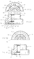
- the hollow body element 10 consists of an essentially cylindrical body made of metal, with an end face 12 which, after the element has been attached to a plate-shaped component, faces it.
- the end face 12 has an annular recess 14 which is arranged within a raised annular contact surface 16, the bottom surface 18 of the annular recess extending as far as the bore 20 of the hollow body element 10.
- the bore 20 has a central axis 22, which also represents the longitudinal axis of the hollow body element, and is designed here as a threaded bore with a thread 24, so that the hollow body element shown here is a nut element.
- the bottom surface 18 of the annular recess 14 passes over an annular shoulder 26 into an annular surface 28 with the outer diameter of the annular surface 28 being slightly larger than the outer diameter D of the thread 24 provided in the bore 20. It can be seen that the bore 20 or the thread 24, the annular surface 28, the annular shoulder 26 and the annular recess 14 and also the contact surface 12 are coaxial with the central axis 22 of the hollow body element 10.
- the further end face 30 of the hollow body element is flat in this example and only provided with a small recess 32 which forms a clean transition to the thread 24.
- the stepped lateral surface 34 of the hollow body element merges into the end face 12 over a small radius 36, this radius 36 preferably being smaller than 0.5 mm, for example 0.3 mm.
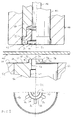
- depressions 38 are provided in the annular contact surface, which, as can be seen in FIG. 2, are approximately wedge-shaped and theirs have greatest depth at the transition into the side wall 15 of the annular recess 14.
- the depressions 38 are approximately rectangular, as can be seen in FIG. 1. These depressions are produced during the cold hammering during the production of the nut element and the corresponding deformation of the hollow body blank leads to bead-like projections 40 in the side wall of the annular depression 14, these projections, as can be clearly seen on the left-hand side of FIG. 2, leading to local undercuts 41 in FIG Guide the side wall of the annular recess 14.
- Suitable materials for the hollow body elements are all materials that reach the strength values of class 8 according to the Isostandard during cold forming, for example a 35 B2 alloy according to DIN 1654.
- the hollow body elements or nut elements formed in this way are suitable for all commercially available steel materials ductile sheet metal parts as well as for aluminum or magnesium or their alloys.
- the nuts can also be formed in other materials, for example in an aluminum alloy, in particular in an aluminum alloy of higher strength.
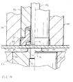
- FIG. 3 shows the hollow body element 10 according to the invention in a setting head 44 which is only partially shown and which has a stamp 46 and a stamp arranged coaxially to the stamp 46 Has punch 48.
- a setting head of this type is known in principle from the above-mentioned German publications, ie DE-PS 34 46 978 and DE-OS 38 35 556.3.
- a die 50 which, as shown in FIG. 7A, is inserted, for example, as a cylindrical component in a cylindrical bore 51 of a lower tool 52 of a press and at the correct height flush with the surface of the lower tool 52 by means of a Spacer 54 is held.
- the die 50 has a central bore 56 which merges into a larger bore 60 via an annular shoulder 58.
- the front end 62 of the die 50 has a flat surface 64 which lies flush with the surface 66 of the lower tool 52.
- the end face of the die 50 has a shaped hole shoulder 68.
- the bore 56 which forms the hole in the shaped hole shoulder 68, has an annular cutting edge 70 which has an inner diameter which corresponds to that of the bore in the hollow body element.
- the end face 72 which is arranged coaxially to the longitudinal axis 22 and which is at least substantially perpendicular to this axis, has a rounded drawing edge 74 at the transition to the lateral surface of the shaped hole heel 68.
- a plurality of lugs 76 are arranged around the shaped hole at intervals, six six such lugs being provided in this example, which are evenly arranged around the shaped hole shoulder 68.
- the lugs 76 have an inclined surface 78 and are raised both on the outer surface of the shaped hole heel 68 and on the flat end surface 64 of the die 50.
- the lugs 76 which are rounded on all surfaces, are somewhat narrower than the depressions 38 in the annular contact surface 16 of the nut element 10.
- the setting head 44 itself is arranged in a manner known per se on the upper tool of a press and, in the usual manner, is designed in such a way that the respective nut elements 10 enter the bore 80 of the setting head 44 via an oblique channel and then by means of the stamp 46 can be felt up to the front end of the setting head when the press is closed.
- the mother elements can also be held during this movement, for which devices are known, for example from the PCT application with the publication number WO 93/19890.
- the setting head moves from the position in FIG. 3 to the position in FIG. 4.
- the lower end 77 of the setting head 44 succeeds in this way in contact with the sheet metal part 42 and this is in turn pressed against the end face 72 of the die 50.
- a further downward movement of the housing 79 of the setting head is prevented at this stage, the housing 79 of the setting head moves back slightly compared to the downward moving tool of the press.
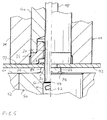
- the upper tool of the press drives but the punch further down first into the position according to FIG. 5.
- a punch 82 is cut from the sheet metal part 42 by the punch 48 in cooperation with the cutting edge 70 of the shaped hole heel 68 of the die 50, as in the following drawing of FIG. 5 is shown.
- a punched hole 83 is created in the sheet metal part 42. From this drawing, one notices that the punch 48 is slidably received in the bore 56 of the die 50 as well as in the bore 20 of the hollow body element 10.
- the slug 82 can be disposed of through the bore 60 of the die 50, the large diameter of this bore 60 compared to the bore 56 ensuring that the slug moves easily under gravity and does not get caught.
- the housing 79 of the setting head 44 and the punch 46 are moved further downward together, as a result of which the shaped-hole heel 68 or more precisely the rounded pulling edge 74 of the shaped-hole heel has a collar 75 made of the sheet metal material formed around the punch hole 83 to widen the punch hole.
- This deformation continues until the final stage as shown in FIG. 7, and it can be seen from FIG. 7 that the shaped-hole heel 68 has deformed the sheet metal material or the collar 75 in such a way that they form-fit in the annular recess 14 of the hollow body element and is pressed into the undercuts 40.
- the press opens again and the workpiece 42 with the attached hollow body element is ejected from the press or removed from the press and then presents itself as shown in FIG. 8.
- the inner diameter of the collar 75 of the sheet metal part 42 is slightly larger than the outer diameter of the thread 24, so that the sheet metal part cannot prevent the insertion of a bolt.
- the bolt fitting into the thread 24 is usually inserted in the direction of arrow 86 in FIG. 8 and is usually used to fasten a second sheet metal part to the sheet metal part 42. From Fig. 8 it is clear that there is a considerable annular contact surface, so that the surface pressure can be easily kept within permissible limits dependent on the material, even with a hollow body element with a comparatively small diameter.
- the depressions 88 produced by the lugs 76 in the sheet metal part can also be seen in FIG. 8.
- hollow body elements shown here all have a circular-cylindrical outer surface, ie have a circular cross-section in plan view, other cross-sectional shapes, for example polygonal ones, can also be used or oval or grooved cross-sectional shapes are used.
- the expression ring-shaped is also understood to mean not only circular rings, but also ring shapes somewhat different from a circular ring shape, such as a polygon.
- the side wall 41 of the annular recess 14 can also be represented as a polygon or a multi-sided figure.
- annular projection 100 in the bottom region of the annular recess 14.
- This annular projection is not to be regarded as a pilot part, since it only enables the use of a reduced thread or a shortening of the height of the hollow body element, but otherwise no function Has.
- this projection 100 with lugs and / or depressions, an additional anti-rotation device being achievable when the sheet metal part is deformed against the lugs and / or depressions.
- Such an embodiment with lugs 102 and indentations 104 can be seen in FIG. 12, the undercut not being the result of the formation of local indentations such as 38 in FIG.
- the annular contact surface 16 is provided with an annular recess 108 which, for example, has a semicircular cross section and is pressed in at several circumferential locations in order to form bead-like projections 40, as in the embodiment of FIG. 1.
- the die should have a corresponding profiling, so that the sheet metal part lies flush against the entire contact surface.
- the annular recess 108 can also be formed in the manner shown in FIG. H. viewed as a corrugated annular recess in plan view. If the die has a shape that is complementary to this, the required anti-rotation is ensured by this annular recess.
- This annular recess can also be designed so that the inner side wall of the annular recess 14 receives projections 40, which also form undercuts which serve to generate the required squeezing resistance and also offer additional security against rotation.
- a particular advantage of the hollow body element according to the invention is that a hollow body element with sheets of different thicknesses can be used, for example sheets in the range from 0.75 mm to 2.25 mm. It is only necessary to use the appropriate die, whereby the thimble hole should have a larger diameter in the case of thinner sheets than in the case of thicker sheets.
- the hollow body element can be a hollow body which is only provided with a thread after it has been attached to a sheet metal part, for example by a self-tapping screw.
Priority Applications (1)
| Application Number | Priority Date | Filing Date | Title |
|---|---|---|---|
| EP99115892A EP0957273B1 (fr) | 1995-08-18 | 1996-08-14 | Elément de fixation et méthode de fabrication |
Applications Claiming Priority (2)
| Application Number | Priority Date | Filing Date | Title |
|---|---|---|---|
| DE19530466 | 1995-08-18 | ||
| DE19530466A DE19530466A1 (de) | 1995-08-18 | 1995-08-18 | Hohlkörperelement, Matrize zur Anwendung mit dem Hohlkörperelement, Verfahren zur Anbringung des Hohlkörperelementes an ein plattenförmiges Bauteil und Zusammenbauteil |
Related Child Applications (1)
| Application Number | Title | Priority Date | Filing Date |
|---|---|---|---|
| EP99115892A Division EP0957273B1 (fr) | 1995-08-18 | 1996-08-14 | Elément de fixation et méthode de fabrication |
Publications (2)
| Publication Number | Publication Date |
|---|---|
| EP0759510A1 true EP0759510A1 (fr) | 1997-02-26 |
| EP0759510B1 EP0759510B1 (fr) | 2000-03-29 |
Family
ID=7769840
Family Applications (2)
| Application Number | Title | Priority Date | Filing Date |
|---|---|---|---|
| EP99115892A Expired - Lifetime EP0957273B1 (fr) | 1995-08-18 | 1996-08-14 | Elément de fixation et méthode de fabrication |
| EP96113103A Expired - Lifetime EP0759510B1 (fr) | 1995-08-18 | 1996-08-14 | Corps creux, matrice pour le corps creux, méthode pour la fixation d'un corps creux sur un élément en forme plate et ensemble de montage |
Family Applications Before (1)
| Application Number | Title | Priority Date | Filing Date |
|---|---|---|---|
| EP99115892A Expired - Lifetime EP0957273B1 (fr) | 1995-08-18 | 1996-08-14 | Elément de fixation et méthode de fabrication |
Country Status (4)
| Country | Link |
|---|---|
| EP (2) | EP0957273B1 (fr) |
| JP (1) | JP2969163B2 (fr) |
| CA (1) | CA2183298C (fr) |
| DE (3) | DE19530466A1 (fr) |
Cited By (11)
| Publication number | Priority date | Publication date | Assignee | Title |
|---|---|---|---|---|
| EP0842733A2 (fr) * | 1996-11-19 | 1998-05-20 | Profil Verbindungstechnik GmbH & Co. KG | Procédé pour attacher un élément fonctionnel, élément fonctionnel, ensemble de montage, matrice et tête de pose |
| US5882159A (en) * | 1996-08-16 | 1999-03-16 | Profil Verbindungstechnik, Gmbh & Co. | Element, method of attaching the element to a plate-like component, component assembly and die button |
| DE19848617A1 (de) * | 1998-10-21 | 2000-04-27 | Profil Verbindungstechnik Gmbh | Verfahren zur Herstellung einer elektrischen Verbindung zu einem Blechteil und Zusammenbauteil |
| US6146072A (en) * | 1995-08-18 | 2000-11-14 | Profil Verbindungstechnik Gmbh & Co. Kg | Press form element, method of installation and assembly |
| WO2005105364A1 (fr) * | 2004-04-28 | 2005-11-10 | Profil-Verbindungstechnik Gmbh & Co. Kg | Procede et dispositif permettant d'appliquer un element de fixation sur un composant, en particulier sur une piece en tole |
| US7010845B2 (en) | 1998-04-06 | 2006-03-14 | Profil Verbindungstechnik Gmbh & Co., Kg | Method of making a joint between two components |
| EP2479442A1 (fr) | 2011-01-20 | 2012-07-25 | Profil Verbindungstechnik GmbH & Co. KG | Elément de fonction sous la forme d'un élément de compression |
| CN101526102B (zh) * | 2008-02-29 | 2013-02-13 | 形状连接技术有限公司及两合公司 | 包括金属板部和连接其上的螺母元件的组合件及制造方法 |
| EP2644911A2 (fr) | 2012-03-27 | 2013-10-02 | Profil Verbindungstechnik GmbH & Co. KG | Elément de fonction sous la forme d'un élément de compression |
| DE102013218548A1 (de) | 2013-09-16 | 2015-03-19 | Profil Verbindungstechnik Gmbh & Co. Kg | Lochstempel sowie Verfahren zum Durchstanzen eines Werkstücks, das als Schaummaterial und/oder als Sandwichmaterial vorliegt, sowie Verfahren zur Herstellung des Lochstempels |
| US10051924B2 (en) | 2013-11-06 | 2018-08-21 | Profil Verbindungstechnik Gmbh & Co. Kg | Fastener element for attachment to a component, component assembly including the fastener element and method for the manufacture of the component assembly |
Families Citing this family (5)
| Publication number | Priority date | Publication date | Assignee | Title |
|---|---|---|---|---|
| DE10205683A1 (de) * | 2002-02-12 | 2003-08-14 | Profil Verbindungstechnik Gmbh | Verfahren zur Anbringung eines stiftartigen Elements, Zusammenbauteil und Zentrierstift |
| US8533928B2 (en) | 2004-04-28 | 2013-09-17 | Profil Verbindungstechnik Gmbh & Co., Kg | Method and apparatus for the attachment of a fastener element to a component, in particular to a sheet metal part |
| DE102008053346A1 (de) * | 2008-10-27 | 2010-04-29 | Profil Verbindungstechnik Gmbh & Co. Kg | Abstandselement für die Anbringung an einem Blechteil, Zusammenbauteil und Verfahren zu dessen Herstellung |
| CN103619504B (zh) * | 2011-06-02 | 2016-12-28 | 株式会社青山制作所 | 铆接部件的铆接方法以及装置 |
| DE102015102865A1 (de) | 2015-02-27 | 2016-09-01 | Profil Verbindungstechnik Gmbh & Co. Kg | Blechelement mit Loch, Blechteil und Zusammenbauteil sowie Herstellungsverfahren |
Citations (6)
| Publication number | Priority date | Publication date | Assignee | Title |
|---|---|---|---|---|
| DE2545581A1 (de) * | 1975-09-16 | 1977-04-14 | Textron Inc | Selbststauchender befestiger |
| EP0041593A1 (fr) * | 1980-06-06 | 1981-12-16 | Russell, Burdsall & Ward Corporation | Elément de fixation et procédé pour son montage |
| DE3149408A1 (de) * | 1981-12-12 | 1983-06-23 | Erno-Raumfahrttechnik Gmbh, 2800 Bremen | "einpressmutter mit beweglichem mutterteil" |
| US4637766A (en) * | 1985-06-17 | 1987-01-20 | Textron Inc. | Clinch type fastener |
| FR2598189A1 (fr) * | 1986-04-30 | 1987-11-06 | Giraud Jean | Element de fixation, ecrou ou goujon, a sertir |
| EP0437011A1 (fr) * | 1988-03-01 | 1991-07-17 | Textron Inc. | Structure de fixation du type rivet |
Family Cites Families (5)
| Publication number | Priority date | Publication date | Assignee | Title |
|---|---|---|---|---|
| SE7403049L (fr) * | 1973-09-14 | 1975-03-17 | Multifastener Corp | |
| JPS597048B2 (ja) * | 1979-11-17 | 1984-02-16 | 有限会社新城製作所 | クリンチナツト及びその取付方法 |
| JPS57140911A (en) * | 1981-02-24 | 1982-08-31 | Shinjo Seisakusho Kk | Nut and panel assembly and its manufacture |
| CA1228255A (fr) * | 1982-04-30 | 1987-10-20 | Edwin G. Sawdon | Fixation autobloqueuse, et son montage sur toles |
| GB2161571B (en) * | 1984-07-09 | 1987-12-31 | Tolwood Multifasteners | Pierce nut, panel assembly and attachment method |
-
1995
- 1995-08-18 DE DE19530466A patent/DE19530466A1/de not_active Withdrawn
-
1996
- 1996-08-14 DE DE59604817T patent/DE59604817D1/de not_active Expired - Lifetime
- 1996-08-14 EP EP99115892A patent/EP0957273B1/fr not_active Expired - Lifetime
- 1996-08-14 EP EP96113103A patent/EP0759510B1/fr not_active Expired - Lifetime
- 1996-08-14 DE DE59610517T patent/DE59610517D1/de not_active Expired - Lifetime
- 1996-08-14 CA CA002183298A patent/CA2183298C/fr not_active Expired - Lifetime
- 1996-08-16 JP JP8233698A patent/JP2969163B2/ja not_active Expired - Fee Related
Patent Citations (6)
| Publication number | Priority date | Publication date | Assignee | Title |
|---|---|---|---|---|
| DE2545581A1 (de) * | 1975-09-16 | 1977-04-14 | Textron Inc | Selbststauchender befestiger |
| EP0041593A1 (fr) * | 1980-06-06 | 1981-12-16 | Russell, Burdsall & Ward Corporation | Elément de fixation et procédé pour son montage |
| DE3149408A1 (de) * | 1981-12-12 | 1983-06-23 | Erno-Raumfahrttechnik Gmbh, 2800 Bremen | "einpressmutter mit beweglichem mutterteil" |
| US4637766A (en) * | 1985-06-17 | 1987-01-20 | Textron Inc. | Clinch type fastener |
| FR2598189A1 (fr) * | 1986-04-30 | 1987-11-06 | Giraud Jean | Element de fixation, ecrou ou goujon, a sertir |
| EP0437011A1 (fr) * | 1988-03-01 | 1991-07-17 | Textron Inc. | Structure de fixation du type rivet |
Cited By (24)
| Publication number | Priority date | Publication date | Assignee | Title |
|---|---|---|---|---|
| US6146072A (en) * | 1995-08-18 | 2000-11-14 | Profil Verbindungstechnik Gmbh & Co. Kg | Press form element, method of installation and assembly |
| US5882159A (en) * | 1996-08-16 | 1999-03-16 | Profil Verbindungstechnik, Gmbh & Co. | Element, method of attaching the element to a plate-like component, component assembly and die button |
| EP0842733A2 (fr) * | 1996-11-19 | 1998-05-20 | Profil Verbindungstechnik GmbH & Co. KG | Procédé pour attacher un élément fonctionnel, élément fonctionnel, ensemble de montage, matrice et tête de pose |
| EP0842733A3 (fr) * | 1996-11-19 | 1998-12-02 | Profil Verbindungstechnik GmbH & Co. KG | Procédé pour attacher un élément fonctionnel, élément fonctionnel, ensemble de montage, matrice et tête de pose |
| US7010845B2 (en) | 1998-04-06 | 2006-03-14 | Profil Verbindungstechnik Gmbh & Co., Kg | Method of making a joint between two components |
| DE19848617A1 (de) * | 1998-10-21 | 2000-04-27 | Profil Verbindungstechnik Gmbh | Verfahren zur Herstellung einer elektrischen Verbindung zu einem Blechteil und Zusammenbauteil |
| EP1003243A2 (fr) * | 1998-10-21 | 2000-05-24 | Profil Verbindungstechnik GmbH & Co. KG | Procédé de fabrication d'une connexion électrique à une partie en tôle et ensemble de montage |
| US6732431B2 (en) | 1998-10-21 | 2004-05-11 | Profil Verbidungstechnik Gmbh & Co. Kg | Method of manufacturing an electrical connection to a panel |
| EP1003243A3 (fr) * | 1998-10-21 | 2004-05-26 | Profil Verbindungstechnik GmbH & Co. KG | Procédé de fabrication d'une connexion électrique à une partie en tôle et ensemble de montage |
| WO2005105364A1 (fr) * | 2004-04-28 | 2005-11-10 | Profil-Verbindungstechnik Gmbh & Co. Kg | Procede et dispositif permettant d'appliquer un element de fixation sur un composant, en particulier sur une piece en tole |
| CN101526102B (zh) * | 2008-02-29 | 2013-02-13 | 形状连接技术有限公司及两合公司 | 包括金属板部和连接其上的螺母元件的组合件及制造方法 |
| CN103075410B (zh) * | 2008-02-29 | 2016-01-06 | 形状连接技术有限公司及两合公司 | 包括金属板部和连接其上的螺母元件的组合件及制造方法 |
| CN103075410A (zh) * | 2008-02-29 | 2013-05-01 | 形状连接技术有限公司及两合公司 | 包括金属板部和连接其上的螺母元件的组合件及制造方法 |
| EP2479442A1 (fr) | 2011-01-20 | 2012-07-25 | Profil Verbindungstechnik GmbH & Co. KG | Elément de fonction sous la forme d'un élément de compression |
| US8734071B2 (en) | 2011-01-20 | 2014-05-27 | Profil-Verbindungstechnik Gmbh & Co. Kg | Functional element in the form of a press-in element |
| DE102011009012A1 (de) | 2011-01-20 | 2012-07-26 | Profil Verbindungstechnik Gmbh & Co. Kg | Funktionselement in Form eines Einpresselements |
| EP2644911A2 (fr) | 2012-03-27 | 2013-10-02 | Profil Verbindungstechnik GmbH & Co. KG | Elément de fonction sous la forme d'un élément de compression |
| DE102013204958A1 (de) | 2012-03-27 | 2013-10-02 | Profil Verbindungstechnik Gmbh & Co. Kg | Funktionselement in Form eines Einpresselements |
| DE102013218548A1 (de) | 2013-09-16 | 2015-03-19 | Profil Verbindungstechnik Gmbh & Co. Kg | Lochstempel sowie Verfahren zum Durchstanzen eines Werkstücks, das als Schaummaterial und/oder als Sandwichmaterial vorliegt, sowie Verfahren zur Herstellung des Lochstempels |
| EP2863071A1 (fr) | 2013-09-16 | 2015-04-22 | Profil Verbindungstechnik GmbH & Co. KG | Poinçon de trou et également un procédé pour le perçage d'une pièce à usiner qui est présent comme un matériau en mousse et/ou en tant que matériau sandwich et également un procédé pour la fabrication de la perforatrice. |
| US9976589B2 (en) | 2013-09-16 | 2018-05-22 | Profil Verbindungstechnik Gmbh & Co. Kg | Hole punch and also a method for the piercing of a workpiece which is present as a foam material and/or as a sandwich material and also a method for the manufacture of the hole punch |
| US10718369B2 (en) | 2013-09-16 | 2020-07-21 | Profil Verbindungstechnik Gmbh & Co. | Hole punch and also a method for the piercing of a workpiece which is present as a foam material and/or as a sandwich material and also a method for the manufacture of the hole punch |
| US10788071B2 (en) | 2013-09-16 | 2020-09-29 | Profil Verbindungstechnik Gmbh & Co. Kg | Hole punch and also a method for the piercing of a workpiece which is present as a foam material and/or as a sandwich material and also a method for the manufacture of the hole punch |
| US10051924B2 (en) | 2013-11-06 | 2018-08-21 | Profil Verbindungstechnik Gmbh & Co. Kg | Fastener element for attachment to a component, component assembly including the fastener element and method for the manufacture of the component assembly |
Also Published As
| Publication number | Publication date |
|---|---|
| JPH09189318A (ja) | 1997-07-22 |
| CA2183298A1 (fr) | 1997-02-19 |
| EP0957273A1 (fr) | 1999-11-17 |
| CA2183298C (fr) | 2001-11-20 |
| DE59610517D1 (de) | 2003-07-10 |
| DE19530466A1 (de) | 1997-02-20 |
| EP0957273B1 (fr) | 2003-06-04 |
| DE59604817D1 (de) | 2000-05-04 |
| MX9603440A (es) | 1997-11-29 |
| EP0759510B1 (fr) | 2000-03-29 |
| JP2969163B2 (ja) | 1999-11-02 |
Similar Documents
| Publication | Publication Date | Title |
|---|---|---|
| EP0667936B1 (fr) | Procede de fabrication un element composite etre resistant a l'ejection et de se contourner par presser un element d'insertion dans une piece en tole et element d'insertion convenable pour ce procede | |
| EP1871553B1 (fr) | Procede de production d'elements a corps creux, element a corps creux, piece d'assemblage, outil a suivre compose pour produire des elements a corps creux et laminoir | |
| EP2177776B1 (fr) | Assemblage comprenant un élément de fixation et un élément en tôle et procédé de fabrication d'un tel élément d'ensemble | |
| EP1806509B1 (fr) | Élément fonctionnel, ensemble de montage composés de l'élément fonctionnel et d'une plaque ainsi que d'une procédure de attacher d'un élément fonctionnel | |
| EP2292940B1 (fr) | Elément d'écrou auto-perforant et composant constitué de l'élément d'écrou et d'un élément de tôle | |
| EP1918596B1 (fr) | Rivet aveugle et son utilisation | |
| EP2980426B1 (fr) | Composant d'assemblage comprenant un element a sertir et une partie de tole | |
| EP1725355B1 (fr) | Procede de production d'elements a corps creux, element a corps creux correspondant et outil composite progressif | |
| EP2412991B1 (fr) | Elément d'écrou auto-perforant et composant constitué de l'élément d'écrou et d'un élément de tôle | |
| EP0759510B1 (fr) | Corps creux, matrice pour le corps creux, méthode pour la fixation d'un corps creux sur un élément en forme plate et ensemble de montage | |
| WO1999049227A2 (fr) | Procede, outil et poinçon pour relier des composants a une plaque | |
| DE4410475A1 (de) | Vernietbares Element, Zusammenbauteil mit einem vernietbaren Element sowie Nietmatrize und Verfahren zur Herstellung des Zusammenbauteils | |
| EP3430277B1 (fr) | Elément d'insertion à force autoperforant, assemblage par insertion à force et procédé pour réaliser un tel assemblage par insertion à force | |
| EP1442809B1 (fr) | Procédé de production d'éléments à corps creux | |
| WO2005050034A1 (fr) | Element fonctionnel, composant d'assemblage compose de l'element fonctionnel combine a une tole, procede de fabrication du composant d'assemblage et procede de fabrication de l'element fonctionnel | |
| DE102018117131A1 (de) | Selbststanzendes Element und Zusammenbauteil bestehend aus dem Element und einem Blechteil | |
| EP1003243B1 (fr) | Procédé de fabrication d'une connexion électrique à une partie en tôle et ensemble de montage | |
| WO2002077468A1 (fr) | Element fonctionnel, piece d'assemblage comprenant une piece de tole et un element fonctionnel, et procede permettant la fixation d'un element fonctionnel a une piece de tole | |
| WO2002083357A1 (fr) | Procede pour monter un element fonctionnel sur un composant et outil utilise a cet effet | |
| EP3564545B1 (fr) | Composant d'assemblage comprenant un composant et d'un élément doté d'une partie de tête et d'un col disposé sur un côté de la partie de tête ainsi que son procédé de fabrication | |
| DE102019110635A1 (de) | Zusammenbauteil bestehend aus einem Bauteil und einem Element mit einem Kopfteil und einem auf einer Seite des Kopfteils angeordneten Kragen sowie Herstellungsverfahren | |
| WO2002081145A2 (fr) | Procede pour monter un element fonctionnel sur une piece et outil correspondant | |
| EP2266725A2 (fr) | Elément de corps creux | |
| EP2042750A2 (fr) | Procédé d'application d'un élément de fonction sur une pièce en tôle et composant d'ensemble |
Legal Events
| Date | Code | Title | Description |
|---|---|---|---|
| PUAI | Public reference made under article 153(3) epc to a published international application that has entered the european phase |
Free format text: ORIGINAL CODE: 0009012 |
|
| AK | Designated contracting states |
Kind code of ref document: A1 Designated state(s): DE FR GB IT |
|
| 17P | Request for examination filed |
Effective date: 19970325 |
|
| GRAG | Despatch of communication of intention to grant |
Free format text: ORIGINAL CODE: EPIDOS AGRA |
|
| 17Q | First examination report despatched |
Effective date: 19990203 |
|
| GRAG | Despatch of communication of intention to grant |
Free format text: ORIGINAL CODE: EPIDOS AGRA |
|
| GRAH | Despatch of communication of intention to grant a patent |
Free format text: ORIGINAL CODE: EPIDOS IGRA |
|
| GRAH | Despatch of communication of intention to grant a patent |
Free format text: ORIGINAL CODE: EPIDOS IGRA |
|
| GRAA | (expected) grant |
Free format text: ORIGINAL CODE: 0009210 |
|
| ITF | It: translation for a ep patent filed |
Owner name: BARZANO' E ZANARDO MILANO S.P.A. |
|
| AK | Designated contracting states |
Kind code of ref document: B1 Designated state(s): DE FR GB IT |
|
| REF | Corresponds to: |
Ref document number: 59604817 Country of ref document: DE Date of ref document: 20000504 |
|
| ET | Fr: translation filed | ||
| GBT | Gb: translation of ep patent filed (gb section 77(6)(a)/1977) |
Effective date: 20000619 |
|
| PLBE | No opposition filed within time limit |
Free format text: ORIGINAL CODE: 0009261 |
|
| STAA | Information on the status of an ep patent application or granted ep patent |
Free format text: STATUS: NO OPPOSITION FILED WITHIN TIME LIMIT |
|
| 26N | No opposition filed | ||
| REG | Reference to a national code |
Ref country code: GB Ref legal event code: IF02 |
|
| REG | Reference to a national code |
Ref country code: GB Ref legal event code: 732E |
|
| REG | Reference to a national code |
Ref country code: GB Ref legal event code: 732E |
|
| REG | Reference to a national code |
Ref country code: FR Ref legal event code: TP Ref country code: FR Ref legal event code: CD Ref country code: FR Ref legal event code: CA |
|
| REG | Reference to a national code |
Ref country code: FR Ref legal event code: GC |
|
| REG | Reference to a national code |
Ref country code: FR Ref legal event code: GC |
|
| REG | Reference to a national code |
Ref country code: FR Ref legal event code: RG Effective date: 20150206 |
|
| REG | Reference to a national code |
Ref country code: FR Ref legal event code: PLFP Year of fee payment: 20 |
|
| PGFP | Annual fee paid to national office [announced via postgrant information from national office to epo] |
Ref country code: FR Payment date: 20150626 Year of fee payment: 20 |
|
| PGFP | Annual fee paid to national office [announced via postgrant information from national office to epo] |
Ref country code: GB Payment date: 20150819 Year of fee payment: 20 |
|
| PGFP | Annual fee paid to national office [announced via postgrant information from national office to epo] |
Ref country code: IT Payment date: 20150824 Year of fee payment: 20 |
|
| PGFP | Annual fee paid to national office [announced via postgrant information from national office to epo] |
Ref country code: DE Payment date: 20151030 Year of fee payment: 20 |
|
| REG | Reference to a national code |
Ref country code: DE Ref legal event code: R071 Ref document number: 59604817 Country of ref document: DE |
|
| REG | Reference to a national code |
Ref country code: GB Ref legal event code: PE20 Expiry date: 20160813 |
|
| PG25 | Lapsed in a contracting state [announced via postgrant information from national office to epo] |
Ref country code: GB Free format text: LAPSE BECAUSE OF EXPIRATION OF PROTECTION Effective date: 20160813 |