EP2266725A2 - Elément de corps creux - Google Patents
Elément de corps creux Download PDFInfo
- Publication number
- EP2266725A2 EP2266725A2 EP10012580A EP10012580A EP2266725A2 EP 2266725 A2 EP2266725 A2 EP 2266725A2 EP 10012580 A EP10012580 A EP 10012580A EP 10012580 A EP10012580 A EP 10012580A EP 2266725 A2 EP2266725 A2 EP 2266725A2
- Authority
- EP
- European Patent Office
- Prior art keywords
- hollow body
- component
- profile
- beams
- body element
- Prior art date
- Legal status (The legal status is an assumption and is not a legal conclusion. Google has not performed a legal analysis and makes no representation as to the accuracy of the status listed.)
- Withdrawn
Links
- 229910052751 metal Inorganic materials 0.000 claims description 26
- 239000002184 metal Substances 0.000 claims description 26
- 238000004080 punching Methods 0.000 claims description 17
- 230000000295 complement effect Effects 0.000 claims 2
- 238000003825 pressing Methods 0.000 abstract description 3
- 230000000750 progressive effect Effects 0.000 description 42
- 238000000034 method Methods 0.000 description 41
- 230000008569 process Effects 0.000 description 24
- 238000004519 manufacturing process Methods 0.000 description 21
- 238000000926 separation method Methods 0.000 description 21
- 239000002131 composite material Substances 0.000 description 12
- 238000005520 cutting process Methods 0.000 description 9
- 150000001875 compounds Chemical class 0.000 description 8
- 239000000463 material Substances 0.000 description 7
- 230000035515 penetration Effects 0.000 description 5
- 238000012545 processing Methods 0.000 description 5
- 230000006835 compression Effects 0.000 description 4
- 238000007906 compression Methods 0.000 description 4
- 210000003128 head Anatomy 0.000 description 4
- 238000002360 preparation method Methods 0.000 description 4
- 230000015572 biosynthetic process Effects 0.000 description 3
- 238000013461 design Methods 0.000 description 3
- 238000006073 displacement reaction Methods 0.000 description 3
- 229910045601 alloy Inorganic materials 0.000 description 2
- 239000000956 alloy Substances 0.000 description 2
- 239000011324 bead Substances 0.000 description 2
- 230000002349 favourable effect Effects 0.000 description 2
- 238000003197 gene knockdown Methods 0.000 description 2
- 230000005484 gravity Effects 0.000 description 2
- 238000003754 machining Methods 0.000 description 2
- 238000005482 strain hardening Methods 0.000 description 2
- 229910000838 Al alloy Inorganic materials 0.000 description 1
- 101001108245 Cavia porcellus Neuronal pentraxin-2 Proteins 0.000 description 1
- 229910000861 Mg alloy Inorganic materials 0.000 description 1
- 229910000831 Steel Inorganic materials 0.000 description 1
- 230000009471 action Effects 0.000 description 1
- 229910052782 aluminium Inorganic materials 0.000 description 1
- XAGFODPZIPBFFR-UHFFFAOYSA-N aluminium Chemical compound [Al] XAGFODPZIPBFFR-UHFFFAOYSA-N 0.000 description 1
- 238000010276 construction Methods 0.000 description 1
- 230000000694 effects Effects 0.000 description 1
- 238000004049 embossing Methods 0.000 description 1
- 230000006872 improvement Effects 0.000 description 1
- 238000003780 insertion Methods 0.000 description 1
- 230000037431 insertion Effects 0.000 description 1
- 238000005304 joining Methods 0.000 description 1
- 210000001331 nose Anatomy 0.000 description 1
- 238000007493 shaping process Methods 0.000 description 1
- 239000010959 steel Substances 0.000 description 1
- 238000012549 training Methods 0.000 description 1
- 230000007704 transition Effects 0.000 description 1
- 238000011282 treatment Methods 0.000 description 1
Images


Classifications
-
- B—PERFORMING OPERATIONS; TRANSPORTING
- B21—MECHANICAL METAL-WORKING WITHOUT ESSENTIALLY REMOVING MATERIAL; PUNCHING METAL
- B21K—MAKING FORGED OR PRESSED METAL PRODUCTS, e.g. HORSE-SHOES, RIVETS, BOLTS OR WHEELS
- B21K27/00—Handling devices, e.g. for feeding, aligning, discharging, Cutting-off means; Arrangement thereof
- B21K27/06—Cutting-off means; Arrangements thereof
-
- B—PERFORMING OPERATIONS; TRANSPORTING
- B21—MECHANICAL METAL-WORKING WITHOUT ESSENTIALLY REMOVING MATERIAL; PUNCHING METAL
- B21J—FORGING; HAMMERING; PRESSING METAL; RIVETING; FORGE FURNACES
- B21J13/00—Details of machines for forging, pressing, or hammering
- B21J13/02—Dies or mountings therefor
-
- B—PERFORMING OPERATIONS; TRANSPORTING
- B21—MECHANICAL METAL-WORKING WITHOUT ESSENTIALLY REMOVING MATERIAL; PUNCHING METAL
- B21J—FORGING; HAMMERING; PRESSING METAL; RIVETING; FORGE FURNACES
- B21J9/00—Forging presses
- B21J9/02—Special design or construction
- B21J9/022—Special design or construction multi-stage forging presses
-
- B—PERFORMING OPERATIONS; TRANSPORTING
- B21—MECHANICAL METAL-WORKING WITHOUT ESSENTIALLY REMOVING MATERIAL; PUNCHING METAL
- B21K—MAKING FORGED OR PRESSED METAL PRODUCTS, e.g. HORSE-SHOES, RIVETS, BOLTS OR WHEELS
- B21K1/00—Making machine elements
- B21K1/64—Making machine elements nuts
- B21K1/68—Making machine elements nuts from round or profiled bars
-
- B—PERFORMING OPERATIONS; TRANSPORTING
- B21—MECHANICAL METAL-WORKING WITHOUT ESSENTIALLY REMOVING MATERIAL; PUNCHING METAL
- B21K—MAKING FORGED OR PRESSED METAL PRODUCTS, e.g. HORSE-SHOES, RIVETS, BOLTS OR WHEELS
- B21K1/00—Making machine elements
- B21K1/64—Making machine elements nuts
- B21K1/70—Making machine elements nuts of special shape, e.g. self-locking nuts, wing nuts
- B21K1/702—Clinch nuts
-
- F—MECHANICAL ENGINEERING; LIGHTING; HEATING; WEAPONS; BLASTING
- F16—ENGINEERING ELEMENTS AND UNITS; GENERAL MEASURES FOR PRODUCING AND MAINTAINING EFFECTIVE FUNCTIONING OF MACHINES OR INSTALLATIONS; THERMAL INSULATION IN GENERAL
- F16B—DEVICES FOR FASTENING OR SECURING CONSTRUCTIONAL ELEMENTS OR MACHINE PARTS TOGETHER, e.g. NAILS, BOLTS, CIRCLIPS, CLAMPS, CLIPS OR WEDGES; JOINTS OR JOINTING
- F16B37/00—Nuts or like thread-engaging members
- F16B37/04—Devices for fastening nuts to surfaces, e.g. sheets, plates
- F16B37/06—Devices for fastening nuts to surfaces, e.g. sheets, plates by means of welding or riveting
- F16B37/062—Devices for fastening nuts to surfaces, e.g. sheets, plates by means of welding or riveting by means of riveting
- F16B37/068—Devices for fastening nuts to surfaces, e.g. sheets, plates by means of welding or riveting by means of riveting by deforming the material of the support, e.g. the sheet or plate
Definitions
- the present invention relates to a method for producing hollow body elements, such as nut elements, for attachment to usually made of sheet metal components, in particular for the production of hollow body elements with an at least substantially square or rectangular outer contour by cutting individual elements of one in the form of a profile bar or a coil present profile after prior punching of holes in the profile, optionally with subsequent formation of a threaded cylinder using a progressive tool with multiple workstations in which respective operations are performed. Furthermore, the present invention relates to a profile for use in such a method, hollow body elements, which are produced by the method and a follow-on composite tool for performing the method.
- a method of the type mentioned and corresponding hollow body elements are for example from the WO 01/72449 A2 known. A similar procedure is also from the US-A-4.971499 known. Rectangular hollow body elements are also sold by the company profile joining GmbH & Co. KG in Germany under the name HI rectangular nut.
- Object of the present invention is to further develop the method of the type mentioned so that hollow body elements, in particular rectangular nut elements, can be produced inexpensively.
- the hollow body elements should have mechanical properties similar to those of the hollow body elements, which after the WO 01/72449 A2 or according to the German utility model 202 05 192.7 be produced, at least equal to, for example, a high Ausziehwiderstand, an excellent security against twisting and beyond a reduced notch effect, so that the fatigue properties of assembly components, consisting of a usually made of sheet metal component and attached to this hollow body elements, even under dynamic loads become.
- the procedure is such that in each workstation for each profile two machining operations are carried out simultaneously for each stroke of the progressive tool.
- the profile used for example, have a shape that already from the WO 01/72449 or from DE Gbm 202 05 192.7 is known, for example, a profile which is at least substantially rectangular in cross-section, on the later side facing the component two spaced from each other, extending parallel to the longitudinal sides of the profile and in cross-section also at least substantially rectangular bar through a groove which is wider in comparison to the beams and rectangular in cross-section is separated from one another and has a depth which at least essentially corresponds to the height of the respective beams.
- the inner side surfaces of the beams of the profile may be perpendicular to the underside of the profile or the beams may each have on the inner side an inclined flank, which forms an undercut.
- a profile could be chosen in which the two beams are bounded by respective grooves which are also parallel to the Longitudinal sides of the profile, have an at least substantially rectangular cross-section and have a depth corresponding to the height of the respective beams, wherein the one side of the groove, which forms an inner edge of the respective beam and the second side of each groove are inclined, so that a dovetail-like groove cross section is present.
- training in which the side surfaces of the grooves are perpendicular to the bottom of the profile, ie do not form undercuts.
- the number of workstations in which an increase in the length of the profile is to be feared by the processing carried out can be limited to two or a maximum of three, namely the steps the piercing process as well as the piercing process and the possibly separately provided cupping process, wherein the cupping process can be combined with the piercing process and / or with the piercing process.
- the follow-on composite tool according to the invention can be designed so that the profile certain expansion possibilities are granted in the amount or in the width, further reducing the problem of elongation, further simplify the design of the progressive tool and ultimately also no disadvantages in the finished hollow body elements to bring oneself.
- the hollow body elements according to the invention as well as the follow-on composite tool used according to the invention can be taken from the figures and the subsequent description of the figures.
- Fig. 1 shows a portion of an elongated profile, which in itself from the WO 01/72499 is known and that, as well as the other profiles described in this application and also other comparable profiles, which are processed in a progressive tool 10 to produce hollow elements, for example, mother elements having a substantially rectangular or square shape.
- a thread must be cut or made in the hole of the hollow body member. This is usually done outside of the progressive tool in a separate machine. It is also possible to produce the thread only after attachment of the hollow body member to a sheet metal part, for example by means of a thread forming or thread cutting Screw.
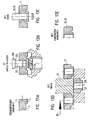
- a first progressive compound tool for the production of hollow body elements from the profile of Fig. 1 or a similar profile is in Fig. 2 shown in longitudinal section, wherein the longitudinal section is made through the center of the profile.
- a lower plate 12 which is usually attached to a press table, either directly or indirectly via an intermediate plate, not shown.
- the lower plate 12 carries a plurality of columns 14, four in this example, two of which are apparent, namely the two columns which lie behind the cutting plane.
- another plate 16 which is usually attached to the upper die plate of the press or to an intermediate plate of the press.
- guides 18 are screwed (for example by means of screws, which are not shown here), wherein the guides 18 are designed to slide in accordance with the lifting movement of the press up and down the columns 14.
- the profile 1 is advanced in the direction of arrow 20 at each stroke of the press, by an amount which is twice the longitudinal dimension L of the individual hollow body elements produced from the profile.
- the follow-on composite tool in this example comprises four workstations A, B, C, D, in which two treatments are made simultaneously at each stroke of the press.
- a knock-down punch 22 is used to separate two hollow-body elements from the profile 1 at each stroke of the press.
- the right side of the punch cuts through the profile at a separation point, which is behind the first hollow body element, ie the hollow body element 21 in Fig. 3 located as well as at a separation point behind the second hollow body element 21 '.
- the progressive tool is in the Fig. 2 and 3 shown in the closed position, in which the two hollow body elements 21 and 21 'have just been separated from the profile 1.
- the cam 27 presses on the right side of the nut member 21 and tilts this in the inclined position, on the right side of the Fig. 3 is apparent.
- the nut member 21 then falls on a chute from the working area of the progressive tool and can, for example, in the position according to Fig. 2 then be led out laterally from the progressive compound tool, for example via its side chute under the action of gravity or with a blast of compressed air, etc.
- the second hollow body element 21 falls through a hole 28 in the tee die 30 and then through corresponding holes 32, 34, 36 and 38, which are formed in plates 40, 42, 44 and 12.
- the bores or the hole 38 in the plate 12 can lead to another hole (not shown) in the press table or in a possibly provided intermediate plate between the plate 12 and the press table, which allows the removal of the nut elements such as 21 ', for example under the By gravity or by a lateral chute or by applying a blast of compressed air.
- the plate 44 is bolted to the plate 12 via screws, not shown.
- the plate 42 consists of a plurality of plate sections, which are assigned to the respective work stations, which are screwed to the continuous plate 44 via further, not shown screws (since arranged outside the plane of the sectional view).
- the continuous plate 40 is also bolted to the sections of the plate 42, again by means not shown screws.
- Above the continuous plate 40 are again plate sections 50, 52, 54, 56, 58 and 60, which in turn are bolted to the plate 40.
- the plate 50 is a support plate, which forms a lower guide for the profile 1, more precisely for the top 4 of the profile 1, which forms the underside in this illustration.
- the plate sections 52, 54 and 56 are associated with the work stations A, B and C, while the plate sections 58 and 60, which form a receptacle for the tee die 30, are associated with the workstation D.
- the parting plane of the progressive tool 10 is located above the profile 1 and is T in Fig. 3 designated.
- plate sections 72, 74, 76, 78 and 80 which are bolted to a continuous plate 82 - again on screws, not shown. Further, the plate 82 is bolted to the upper plate 16.
- the plates 72, 74, 76, 78 and 80 are raised with the plate 22 and the top plate 16 to such an extent that the two punches 84, 86 and the two top punches 88 and 90, such as also the dies 92 and 94 which cooperate with the puncturing punches 64, 66 and also the tee punches 22 out of engagement with the profile strip 1 arrive.
- the profile strip 1 can be further pushed by twice the length dimension of the hollow body elements 21 in preparation for the next stroke of the press.
- the workstations A and B have a length dimension, ie in the direction of movement 20 of the profile strip 1, which corresponds to four times the length dimension of a hollow body element 21.
- the workstation C has a length dimension corresponding to three times the length dimension of a hollow body member 21, while the work station D has a length dimension having a multiple of the length dimension of the hollow body member 21, which is six times in this example.
- the perforation dies 100, 102 which cooperate with the punches 84, 86, have a central bore 104, 106, respectively, which are aligned with further bores 108, 110 in insert sleeves 112, 114, which make it possible to produce the punches 116, 118 to dispose of.
- Guiding elements which may be formed, for example by cheeks of the plates 50, 52, 54, 56 and 58, which ensure that the profile strip follows the desired trajectory through the progressive tool. It may be provided a slight lateral clearance, which allows a possible expansion of the profile strip in the transverse direction.
- FIG. 4 and 5 show an alternative embodiment of a progressive compound tool 10 designed to produce a profile strip which is shown in FIG Fig. 24A and 24C, respectively.
- the profile strip 1 in the embodiment according to Fig. 4 capable of being managed in Fig. 1 is shown, ie with the bars 2, 3 down. Furthermore, in this embodiment, all the punches are arranged above the profile strip 1, while the corresponding dies are located below the profile strip.
- the dividing plane T is in this example at the location shown.
- the profile strip 1 must be raised in this embodiment, which is accomplished by spring-loaded devices (not shown), namely the profile strip is raised here by the sprung devices until the top 4 comes into contact with the ceiling 120 of a guide channel 122. At this point, the profile strip 1 in Feed direction 20 are advanced at each stroke of the press.
- the blanket 120 lies between two side cheeks of the guide channel 122, which form the lateral guidance of the profile strip.
- the first work station A is provided with two cut-free punches 126, 128, whose lower ends in cross-section have the same shape as the slots 6 of the profile strip 1 of Fig. 24A or 24C.
- the reference numeral 130 indicates a pin which is in abutment with flats of the cut-free punches 126 and 128, respectively, which form an anti-twist device and thus secure the orientation of the cut-free punches 126 and 128.
- workstation B are the two puncturing punches 64 and 66 which operate with corresponding dies 92 and 94 within the tread strip.
- Workstation C includes the two punches 84 and 86, which cooperate with respective punch dies 100, 102.
- a posture control pin 130 which must engage a hole or hole in the profile strip at each stroke of the press. If this does not succeed, then you know that the profile strip is not aligned correctly. The determination of whether the position is correct or not is made via this pin 130, which is pressed down by a spring 132. If the attitude control pin 130 is displaced upwards, since its front end abuts the profile strip, instead of engaging in the hole, the guided inside the helical compression spring 132 pin 134 is pushed upwards, where it is detected by a proximity sensor 136, which then a shutdown signal for the Press plant generated because of misalignment of the profile strip 1 is a mistake and the press may not be operated.
- the plate with the reference numeral 138 is on the one hand with the plate 16 and on the other hand screwed to the upper tool of the press or an intermediate plate of the press. The plate 138 thus transmits the pressing forces to the individual tools of the follow-on composite tool.
- the reference numerals 140, 142 show two driving pins which cause the punches 84, 86 to be raised with the upper plate. The same function is fulfilled by the pin 144 with respect to the knock-out punch 22.
- the knock-down punch 22 in this embodiment has two pins 146 at its lower end which are biased downwards by the helical compression spring 148. These pins ensure that the nut member 21 'is pushed out of the bore 38 of the die 30 into the bore 38 of the plate 12.
- the plates carrying the upper ends of the scraper dies 126, 128, the puncturing punches 64, 66 and the punch 84, 86 are bolted to the plate 156, which in turn is bolted to the plate 16.
- the reference numeral 158 denotes a guide plate for the position control pin 130 and the tee punch 22 and is adjustably bolted to the overhead plate 160, which in turn is bolted to the plate 16.
- Reference numeral 162 denotes the adjusting means (screw with screw block and lock nut).
- Reference numeral 164 denotes a plate which is bolted to the top of the guide channel 122 (see, for example, the screws 170) and which has various recesses for the clearance dies 126, 128, for the punches 64, 66, for the punches 84, 86, for the tee stamp 22 and the control pin 130th
- a method for producing hollow body elements such as nut elements, for attachment to components usually made of sheet metal is realized.
- the method is used to produce hollow body elements 21, 21 'with an at least substantially square or rectangular outer contour by cutting individual elements of a present in the form of a profile bar or a roll profile 1 after prior punching holes 23 in the profile 1, optionally followed by Forming a threaded cylinder using a progressive tool with multiple workstations A, B, C, D, where respective operations are performed.
- the method is characterized in that in each workstation A, B, C, D for the profile 1 or for a plurality of juxtaposed profiles in each case two machining operations for each stroke of the progressive tool are performed simultaneously. That is, it is in principle possible to process several profiles 1 side by side and at the same time in the same progressive tool, provided that the appropriate number of individual tools, such as puncture punches, punches and associated matrices, is present.
- the knock-off punch 22 cuts through the profile at a first location behind a first hollow body element 21 and at a second location behind a second hollow body element 21 ', wherein the second hollow body element 21' in the direction of the movement of the tee punch transversely to the longitudinal direction of the profile 1 from the movement path of the profile is led out.
- the first hollow body element 21 is led out in the teetering station of the progressive tool at least for the time being generally in the direction of the movement path of the profile.
- Each workstation of the follow-on composite tool has a length in the direction of travel of the profile which corresponds to three times or four times or several times the longitudinal dimension of a finished hollow body element 21, 21 '.
- a free cutting process is carried out, in the second work station B a piercing operation, in the third work station C a piercing operation and in the fourth work station D the separation of two hollow body elements of each profile by means of the tee punch 22.
- the embodiment is preferably such that in the fourth workstation D, a positional control by means of the position control pin 130 is performed.
- the cupping operation may be combined with the wrapping operation, thereby saving the third workstation C.
- the cupping operation is combined with the wrapping process, saving a workstation.
- a spring-loaded cam 27 is biased against the force of spring means 26 with a cam surface 24 inclined to the trajectory of the profile from the leading edge of the leading end of the profile at the exit end of the last work station. After separation of the formed at the front end of the profile hollow body member 21, this is tilted by the spring-loaded cam down to facilitate removal from the progressive tool.
- the punches 64, 66 for performing the puncture operation and the punches 84, 86 for perforating from opposite sides of the tread 1 operate thereon.
- the respective teat punches 68, 70, 88, 90 are used to tap from both sides of the profile strip 1.
- FIGS. 6A to 6F be from a profile according to the Fig. 1 Hollow body elements 21 manufactured, which have a shape similar to the Fig. 4 of the WO 01/72449 and a cross-sectional shape in particular according to Fig. 6A having.
- the profile 1 on the enforcement punches 64 and 66 facing away from the side of the profile of a die 92 and 94 with a cylindrical recess 200th supported which, how Fig. 6B shows, has an inner diameter D which is greater than the formed by the enforcement process elevation 202 in the profile 1, wherein the axial depth H of the recess is dimensioned so that the elevation 202 generated by the clinching operation at its end face 204 is flat, but on its outer side 206 assumes a spherical shape.
- a punch 84, 86 is used which has at least substantially the same diameter as the punch 64, 66.
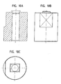
- the profile 1 is at least substantially rectangular in cross-section, with on the later side facing the component two spaced from each other, parallel to the longitudinal sides of the profile and running in cross-section also at least substantially rectangular bars 2, 3, by a comparison to the bars wider, rectangular in cross-section groove 5 separated or formed are, which has a depth which corresponds to the height of the respective beams 2, 3 at least substantially.
- the bars each have an inclined flank 9, 9 'on the inner side, which forms an undercut 11 or 11'.
- the hollow body element then forms as in Figs. 7B to 7D shown.
- the Ringfase 218 at the thread entry is generated by the die 92 and 94, which is used for the enforcing process, here the penetration process according to the Fig. 4 . 5 equivalent.
- the shape of the dies 92 and 94 and the importance of the manufacturing steps in three workstations (including the separation process according to Fig. 8D ) go out of the FIGS. 8A to 8E and the workstations of the corresponding progressive tool 10 are shown in FIG Fig. 9 shown.
- the reference numerals in Fig. 9 largely correspond to those of Fig. 2 . 3 and the description of the Fig. 2 . 3 applies accordingly also for the Fig. 9 ,
- the annular projection of the finished element, ie the pilot part or punching section 25 has no undercut. This is not necessary because the bars are undercut.
- an enforcing punch 64 or 66 is used, with a diameter which at least essentially corresponds to the core diameter of a thread 27 to be formed later in the finished hollow body element, and that the profile is supported on a die 92 when carrying out the penetration process is provided with a tubular projection 230 with a rounded inner edge 232 at the End face and within the annular projection with a bolt 234 with a central elevation 236 is provided which is dimensioned to form a cone-shaped recess 238 in the free end of the survey generated by the enforcement process, which later as Ein 1500konus 238 'trained in a hollow body elements Thread 27 inserted bolt element is used.
- the piercing process is performed with a punch 84 and 86, respectively, which has at least substantially the same diameter as the puncturing punch 64 or 66.
- a die according to the 10A to 10C be used. This process is already described in DE-Gbm 202 05 192.7 and this description also applies here.
- a stepped stamp according to Fig. 13B are used, with a front cylindrical portion 250, which merges via a cone-shaped annular shoulder 252 in a rear portion 254 of larger diameter, the conical annular shoulder 254 in the finished hollow body element in the threaded outlet area forms a Ringfase (256 in Fig. 13D )
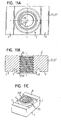
- the Figs. 11A to 11C show a hollow body element that the nut element of Figs. 7A to 7D However, as far as possible corresponds to using the profile 1 according to Fig. 1 was produced. There are thus no undercuts to the element determine.
- the element is either self-piercing introduced into a sheet metal part or not self-piercing in a pre-punched sheet metal part and it is then, as in the Figs. 21A and 21B
- an annular bead 290 formed by displacement of the material from the end face of the pilot member 25 by means of a suitable die, which creates an undercut and the Sheet metal part 292 clamped in the region of the hole edge 294 between itself and the bottom 5 of the groove.
- annular bead and discrete material noses could be applied, which are also formed by displacement of the material from the end face of the pilot member 25 by means of a suitable die, as is known per se.
- FIGS. 12A to 12D show how the element of Figs. 11A to 11C by working from opposite sides of the profile 1 analogous to Fig. 2 and 3 can be made, with only three steps (penetration, punching and separating (separation not shown)).
- the penetration process can be combined with the formation of the chamfer, as in the FIGS. 13A to 13E especially in Fig. 13B is shown, wherein the FIGS. 13A to 13E show the processing of the profile strip with the punch and the punch on the same side of the profile strip. 1
- a ring bevel on the thread outlet can be generated by using a punch with a cone-shaped annular shoulder, as in the embodiment according to Figs. 14A to 14E , especially in Fig. 14C is shown.
- a Ringfase at the thread outlet can be generated by an additional step, as in the embodiment according to Figs. 15A to 15F is shown.
- a bevel stamp is used to generate a Ringfase at the thread outlet.
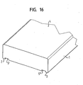
- two beams 2, 3 are provided, which are delimited or formed by respective grooves 5 ', 5 ", which likewise extend parallel to the longitudinal sides of the profile, have an at least substantially rectangular cross-section and have a depth corresponding to the height of the respective beams, wherein the one side of each groove 5 ', 5 ", which forms an inner edge of the respective beam 2 and 3, and also the second side of each groove 5'5" are inclined , so that a dovetail-like groove cross section is present.
- the profile according to Fig. 16 an element 21, 21 'can be used according to the Figs. 17A to 17E getting produced.
- This element essentially corresponds to the element according to Figs. 9A to 9E DE-Gbm 202 05 192.7, except for the special dovetail-like design of the grooves.
- this profile can be edited in a progressive tool with only three workstations including the separation station. The procedure is in the Figs. 18A to 18D shown, although the separation process is not shown, since this step is carried out as before.
- a conical depression 270 is created in the region of the profile 1 between the two grooves 5 ', 5 ", at the same time producing a conical elevation 272 on the side of the profile 1 opposite the depression 270.
- Within the conical depression 270 simultaneously produces a cylindrical projection 274 with a central recess 276, which merges via a cone-shaped annular shoulder 278 in a bottom surface 280, wherein on the side of the conical elevation 272, this has a cylindrical recess 282 in the middle, which has a conical annular surface 284, which transitions into a bottom surface 286.
- the stamper and the piercing die are correspondingly shaped at their face ends to achieve said shaping of the hollow body member.
- a piercing operation is carried out by means of a punch and then the elements are separated from the profile and optionally creates a thread in the perforated area.
- the cone-shaped annular shoulder 278 on the side of the conical recess 270 and the conical annular shoulder 284 on the side of the conical elevation 272 form an insertion aid for a screw or a Ringfase at the threaded outlet.
- the die for attaching the hollow body elements to a sheet metal part is in the Figs. 19A to 19C shown and largely corresponds to the die according to the Figs. 12A, 12B the aforementioned WO-font.
- a profile 1 according to the Fig. 22A respectively. Fig. 22C is used.
- the notches 302 and 304 can be produced in the progressive compound tool, for example in another workstation or combined with an already provided work step. Instead, they can be rolled into the profile 1 during its manufacture or otherwise introduced.
- the hollow body elements are not separated from each other in the progressive tool, but the profile 1 is maintained or used after preparation of the general shape of the hollow body elements in sections or in rewound form and a separation into individual hollow body elements 21, 21 'only then takes place when the profile 1 is used in a setting head for attachment of the hollow body elements to a component. This procedure would facilitate the supply to the setting head.
- notches can also be used with other profile strips, for example with all profile strips mentioned in this application or known in the prior art.
- a profile strip according to Fig. 1 could hollow body elements according to Figs. 23A to 23C getting produced.
- a profile strip according to the Fig. 24A and 26A For this purpose, a profile strip according to the Fig. 24A and 26A
- the progressive compound tool after the Fig. 4 and 5 used.
- a free cutting operation is performed to punch holes in the profile at the boundaries between the individual not yet separated hollow body elements, such as slots 6 or more circular in cross-section, transverse to the longitudinal direction of the profile or in a row across are arranged to the longitudinal direction of the profile to the subsequent separation of the hollow body elements 21, 21 'by means of the tee punch 22 to facilitate.
- the free cutting process is preferably carried out as a first step in the progressive tool 10.
- the profile can be maintained or used after preparation of the general shape of the hollow body elements in sections or in rewound form, with a separation into individual hollow body elements only then takes place when the profile is used in a setting head for attaching the hollow body elements to a component.
- the elongated holes 6 or the row of cylindrical holes should preferably not extend into areas of the profile in which the beams 7, 8 are provided, since the length of the beams is important for the rotation, whereby it is permissible would be to provide a hole in each beam area, unless the beams are thereby undesirably shortened.
- Figs. 26A-26E show a further example of a hollow body element according to the invention, wherein the Figs. 27A and 27B show the same element after attachment to a sheet metal part.
- the hollow body element according to Figs. 27A and 27B is using the device according to Fig. 5 made, using free punch temples 126, 128, each having a cross section with the shape of an hourglass or a bollard.
- This cross-sectional shape is in Fig. 26A drawn, and it can be seen that the cutouts above and below the middle part of the Hollow element 21 in plan view each have the shape of the half cross section 300 and 302 of the free punch temple.
- the method is preferably performed with a profile having in cross-section the shape defined by the outer contour 304 of FIG Fig. 26B is specified.
- the cross-section is at least substantially rectangular, with on the later the component 292, Figs. 27A and 27B facing component side 306 two spaced apart running parallel to the longitudinal sides of the profile and in cross-section also at least substantially rectangular beams 7, 8, which are bounded on the inner side by respective, also in the longitudinal direction of the profile extending grooves 5 ', 5 "
- the respective inner sides 308, 310 of the grooves are higher than the respective outer sides 312, 314 which delimit the respective beams, whereby in the middle region of the longitudinal side of the profile a cross-sectionally rectangular projection 316 is present, whose side facing the component continues to project
- the respective outer sides 312, 314 of the grooves are inclined to form undercuts It would also be conceivable that the respective inner sides 308, 310 of the grooves also or instead of the outer sides of the grooves To put grooves in an inclined position to
- a profile with a cross-sectional shape corresponding to reference numeral 304 of Fig. 26B You can also use the profile according to Fig. 1 use and create the projection 25 with a corresponding piercing operation. That is, in this example, a profile is used, which is at least substantially rectangular in cross-section, with on the component side later facing the component two spaced apart, parallel to the longitudinal sides of the profile and extending in cross-section also at least substantially rectangular Beams 7, 8. These are separated or formed by a groove 5 which is wider in cross section than the beams and has a depth which at least substantially corresponds to the height of the respective beams.
- the profile could be a cross-sectionally rectangular profile without beams, or it could be rectangular in cross-section with a centrally located cross-sectionally rectangular beam such as 316 in FIG Fig. 26 be formed.
- the middle bar 316 would then have sides corresponding to the flanks 308 and 310 in FIG Fig. 26 form, which would create the rotation after attachment of the element in a sheet metal part.
- These pages correspond to flanks 308 and 310 in FIG Fig. 26 could also be inclined, as also related to Fig.
- the required security against squeezing can also be achieved by deforming or embossing metal from the pilot section 25, for example in the sense of displacement from the metal of the element to overlap the sheet metal part, as also described above in connection with other embodiments.
- the projection 25 must be generated with an undercut, for example according to the FIGS. 6A to 6F .
- a profile strip similar to Fig. 1 are used, but in which the inner sides of the beams, ie the sides of the groove 5, are inclined to the bottom surface of the groove 5 to form undercuts. That is, the bars each have on the inner side an inclined flank, which forms an undercut.
- This embodiment can be realized with a projection 25 having either an undercut or no undercut.
- the result of the various production methods is preferably such that a projection 25 is formed in the center of the hollow body element on the component side 306.
- the front end 326 of the projection 25 formed as a punched section protrudes beyond the height of the sides of the beams facing the component and, in plan view, has edges 328, 330 running parallel to it in the region of the beams. These are about two part-circular edges 332, 334, the side shape of the cut-stamp correspond to each other and extend concentrically to the central hole 23 of the element.
- the hollow body element for attachment to a particular consisting of sheet metal component 292 thus has on two opposite sides parallel to each other extending beams 7, 8, which form a rotation with the component 292, and a perpendicular to the component side, centrally disposed hole 23, optionally one Threaded cylinder 29 may have. It is characterized in that on the component side facing the component side 306 of the hollow body member 21, 21 'and concentric to the hole 23, an annular projection 25 is present, which is formed as a punched portion with or without undercut. Furthermore, in the region of each beam 7, 8, the projecting punching section 25 has in plan view a respective edge 328, 330 which runs at least substantially parallel to the adjacent side wall 312, 314 of the respective beam 7, 8.
- the hollow body element is at least approximately I-shaped in plan view, wherein the middle, the transverse members 336, 338 of the I-shape connecting web 340 in the center and in plan view is at least substantially circular and is formed by a cylindrical portion 342 of the web 340 ,
- the sheet material is formed by applying a correspondingly shaped die (not shown) in the grooves 5 ', 5 "and in the undercuts 344, 346 adjacent to the beams 7, 8 and the element 21, 21 'is thus secured against contact forces, the beams at the same time provide a high security against rotation.
- the end face 348 of the stamped portion 25 lies in a plane with the side facing away from the hollow body member 350 of the sheet metal part, so that there is a good Anschraubsituation. Furthermore, it can be seen that the sheet metal deformations in the region of the punching section 25 are all rounded, so that a good resistance to fatigue is to be expected.
- the profile 1 or each profile according to the invention is strictly guided laterally, for example, by fixed guides, but can extend laterally slightly in the direction transverse to the movement path 20. Furthermore, the or each profile 1 can expand freely upwards.
- it is possible according to the invention in particular in embodiments in which in the profile at the separation point between the elements weak points, such as notches or free cuts, provided that the hollow body elements in Subsequent composite tool are not isolated from each other, but the profile after preparation of the hollow body elements in sections or in rewound form is used and a separation into individual hollow body elements takes place only when the profile is used in a setting head for attachment of the hollow body elements to a component.
Landscapes
- Engineering & Computer Science (AREA)
- Mechanical Engineering (AREA)
- Press Drives And Press Lines (AREA)
- Connection Of Plates (AREA)
- Perforating, Stamping-Out Or Severing By Means Other Than Cutting (AREA)
- Punching Or Piercing (AREA)
Applications Claiming Priority (3)
| Application Number | Priority Date | Filing Date | Title |
|---|---|---|---|
| DE102004004589 | 2004-01-29 | ||
| DE102004045159A DE102004045159A1 (de) | 2004-01-29 | 2004-09-17 | Verfahren zur Herstellung von Hohlkörperelementen, Hohlkörperelement sowie Folgeverbundwerkzeug zur Durchführung des Verfahrens |
| EP05001054.5A EP1559488B1 (fr) | 2004-01-29 | 2005-01-19 | Procédé de fabrication d'eléments creux ainsi outil à suivre pour la mise en oeuvre de ce procédé. |
Related Parent Applications (3)
| Application Number | Title | Priority Date | Filing Date |
|---|---|---|---|
| EP05001054.5A Division EP1559488B1 (fr) | 2004-01-29 | 2005-01-19 | Procédé de fabrication d'eléments creux ainsi outil à suivre pour la mise en oeuvre de ce procédé. |
| EP05001054.5A Division-Into EP1559488B1 (fr) | 2004-01-29 | 2005-01-19 | Procédé de fabrication d'eléments creux ainsi outil à suivre pour la mise en oeuvre de ce procédé. |
| EP05001054.5 Division | 2005-01-19 |
Publications (2)
| Publication Number | Publication Date |
|---|---|
| EP2266725A2 true EP2266725A2 (fr) | 2010-12-29 |
| EP2266725A3 EP2266725A3 (fr) | 2017-10-11 |
Family
ID=34813039
Family Applications (1)
| Application Number | Title | Priority Date | Filing Date |
|---|---|---|---|
| EP10012580.6A Withdrawn EP2266725A3 (fr) | 2004-01-29 | 2005-01-19 | Elément de corps creux |
Country Status (3)
| Country | Link |
|---|---|
| EP (1) | EP2266725A3 (fr) |
| DE (1) | DE102004045159A1 (fr) |
| ES (1) | ES2634503T3 (fr) |
Families Citing this family (2)
| Publication number | Priority date | Publication date | Assignee | Title |
|---|---|---|---|---|
| DE102004017866A1 (de) | 2004-04-13 | 2005-11-03 | Profil-Verbindungstechnik Gmbh & Co. Kg | Verfahren zur Herstellung von Hohlkörperelementen, Hohlkörperelement, Zusammenbauteil sowie Folgeverbundwerkzeug zur Durchführung des Verfahrens |
| DE102005024220A1 (de) | 2005-05-25 | 2006-11-30 | Profil Verbindungstechnik Gmbh & Co. Kg | Verfahren zum Herstellen von Hohlkörperelementen, Hohlkörperelement, Zusammenbauteil, Folgeverbundwerkzeug zum Herstellen von Hohlkörperelementen sowie Walzwerk |
Citations (4)
| Publication number | Priority date | Publication date | Assignee | Title |
|---|---|---|---|---|
| US4971499A (en) | 1984-12-24 | 1990-11-20 | Ladouceur Harold A | Nut and panel assembly |
| WO2001072449A2 (fr) | 2000-03-31 | 2001-10-04 | Profil Verbindungstechnik Gmbh & Co. Kg | Procede de production d'elements a corps creux, profil utilise dans ce procede, element a corps creux, composant d'assemblage et matrice |
| WO2001072499A1 (fr) | 2000-03-29 | 2001-10-04 | Alphacan | Procede et ligne de fabrication en continu de tubes en matiere plastique avec etirage bi-axial, et tube en matiere plastique obtenu |
| DE20205192U1 (de) | 2002-04-03 | 2002-11-07 | Profil Verbindungstechnik Gmbh | Profil zur Herstellung von Hohlkörperelementen, Hohlkörperelement sowie Zusammenbauteil |
Family Cites Families (2)
| Publication number | Priority date | Publication date | Assignee | Title |
|---|---|---|---|---|
| US2096623A (en) * | 1935-04-26 | 1937-10-19 | Midland Steel Prod Co | Method of making grommets |
| US2206740A (en) * | 1938-12-08 | 1940-07-02 | Bert L Quarnstrom | Nut and method of forming same |
-
2004
- 2004-09-17 DE DE102004045159A patent/DE102004045159A1/de not_active Withdrawn
-
2005
- 2005-01-19 EP EP10012580.6A patent/EP2266725A3/fr not_active Withdrawn
- 2005-01-19 ES ES05001054.5T patent/ES2634503T3/es active Active
Patent Citations (4)
| Publication number | Priority date | Publication date | Assignee | Title |
|---|---|---|---|---|
| US4971499A (en) | 1984-12-24 | 1990-11-20 | Ladouceur Harold A | Nut and panel assembly |
| WO2001072499A1 (fr) | 2000-03-29 | 2001-10-04 | Alphacan | Procede et ligne de fabrication en continu de tubes en matiere plastique avec etirage bi-axial, et tube en matiere plastique obtenu |
| WO2001072449A2 (fr) | 2000-03-31 | 2001-10-04 | Profil Verbindungstechnik Gmbh & Co. Kg | Procede de production d'elements a corps creux, profil utilise dans ce procede, element a corps creux, composant d'assemblage et matrice |
| DE20205192U1 (de) | 2002-04-03 | 2002-11-07 | Profil Verbindungstechnik Gmbh | Profil zur Herstellung von Hohlkörperelementen, Hohlkörperelement sowie Zusammenbauteil |
Also Published As
| Publication number | Publication date |
|---|---|
| EP2266725A3 (fr) | 2017-10-11 |
| ES2634503T3 (es) | 2017-09-28 |
| DE102004045159A1 (de) | 2005-09-01 |
Similar Documents
| Publication | Publication Date | Title |
|---|---|---|
| EP1871553B1 (fr) | Procede de production d'elements a corps creux, element a corps creux, piece d'assemblage, outil a suivre compose pour produire des elements a corps creux et laminoir | |
| EP1725355B1 (fr) | Procede de production d'elements a corps creux, element a corps creux correspondant et outil composite progressif | |
| EP0720695B1 (fr) | Systeme de fixation autoperforant | |
| EP0993902B1 (fr) | Procédé pour attacher un élément fonctionnel, matrice, élément fonctionnel et ensemble de montage | |
| EP2177776B1 (fr) | Assemblage comprenant un élément de fixation et un élément en tôle et procédé de fabrication d'un tel élément d'ensemble | |
| EP2980426B1 (fr) | Composant d'assemblage comprenant un element a sertir et une partie de tole | |
| EP1442809B1 (fr) | Procédé de production d'éléments à corps creux | |
| EP1202834B1 (fr) | Element fonctionnel, procede pour sa pose dans une piece de tole, element d'assemblage | |
| DE202005010990U1 (de) | Vorrichtung zum Stanzen und/oder Umformen von Werkstücken | |
| DE3610675C2 (de) | Verfahren und Vorrichtung zum Anbringen eines Hohlkörpers an einem tafelförmigen Werkstück | |
| EP1559488B1 (fr) | Procédé de fabrication d'eléments creux ainsi outil à suivre pour la mise en oeuvre de ce procédé. | |
| EP0759510B1 (fr) | Corps creux, matrice pour le corps creux, méthode pour la fixation d'un corps creux sur un élément en forme plate et ensemble de montage | |
| EP1194264B1 (fr) | Procede pour placer un element fonctionnel; matrice; element fonctionnel; element assemble et ensemble poincon | |
| DE102008053346A1 (de) | Abstandselement für die Anbringung an einem Blechteil, Zusammenbauteil und Verfahren zu dessen Herstellung | |
| DE602004000126T2 (de) | Verfahren zur Herstellung von selbststanzenden Muttern | |
| DE3116765C1 (de) | Werkzeug zum Herstellen von Senkloechern oder Passloechern in einem Blech auf einer Stanzmaschine | |
| DE102010011711B4 (de) | Verfahren und Vorrichtung zur spanlosen Herstellung von Verbindungs-, Befestigungs- oder Verschlusselementen aus Metall mit Außengewinde | |
| EP2266725A2 (fr) | Elément de corps creux | |
| DE2907414A1 (de) | Vorrichtung zur anbringung von blechdurchzuegen fuer muttergewinde in hohlprofilen | |
| DE102019110635A1 (de) | Zusammenbauteil bestehend aus einem Bauteil und einem Element mit einem Kopfteil und einem auf einer Seite des Kopfteils angeordneten Kragen sowie Herstellungsverfahren | |
| EP2042751B1 (fr) | Procédé d'application d'un élément de fonction sur une pièce en tôle et composant d'ensemble | |
| DE102005061229B3 (de) | Verfahren und Vorrichtung zum Setzen von selbststanzenden Muttern | |
| DE19949355A1 (de) | Verfahren zur Anbringung eines Funktionselementes; Matrize; Funktionselement; Zusammenbauteil | |
| EP2042750B1 (fr) | Procédé d'application d'un élément de fonction sur une pièce en tôle et composant d'ensemble |
Legal Events
| Date | Code | Title | Description |
|---|---|---|---|
| PUAI | Public reference made under article 153(3) epc to a published international application that has entered the european phase |
Free format text: ORIGINAL CODE: 0009012 |
|
| AC | Divisional application: reference to earlier application |
Ref document number: 1559488 Country of ref document: EP Kind code of ref document: P |
|
| AK | Designated contracting states |
Kind code of ref document: A2 Designated state(s): DE ES FR GB IT |
|
| RIN1 | Information on inventor provided before grant (corrected) |
Inventor name: BABEJ, JIRI Inventor name: VIETH, MICHAEL Inventor name: HUMPERT, RICHARD |
|
| PUAL | Search report despatched |
Free format text: ORIGINAL CODE: 0009013 |
|
| AK | Designated contracting states |
Kind code of ref document: A3 Designated state(s): DE ES FR GB IT |
|
| RIC1 | Information provided on ipc code assigned before grant |
Ipc: B21K 27/06 20060101ALI20170906BHEP Ipc: B21K 1/68 20060101AFI20170906BHEP Ipc: B21J 13/02 20060101ALI20170906BHEP Ipc: B21J 9/02 20060101ALI20170906BHEP Ipc: B21K 1/70 20060101ALI20170906BHEP |
|
| STAA | Information on the status of an ep patent application or granted ep patent |
Free format text: STATUS: THE APPLICATION IS DEEMED TO BE WITHDRAWN |
|
| 18D | Application deemed to be withdrawn |
Effective date: 20180412 |