EP4477902A1 - Support principal de rotor de nacelle pour éolienne - Google Patents
Support principal de rotor de nacelle pour éolienne Download PDFInfo
- Publication number
- EP4477902A1 EP4477902A1 EP24194950.2A EP24194950A EP4477902A1 EP 4477902 A1 EP4477902 A1 EP 4477902A1 EP 24194950 A EP24194950 A EP 24194950A EP 4477902 A1 EP4477902 A1 EP 4477902A1
- Authority
- EP
- European Patent Office
- Prior art keywords
- ring element
- nacelle
- bearing
- inner ring
- outer ring
- Prior art date
- Legal status (The legal status is an assumption and is not a legal conclusion. Google has not performed a legal analysis and makes no representation as to the accuracy of the status listed.)
- Withdrawn
Links
Images
Classifications
-
- F—MECHANICAL ENGINEERING; LIGHTING; HEATING; WEAPONS; BLASTING
- F16—ENGINEERING ELEMENTS AND UNITS; GENERAL MEASURES FOR PRODUCING AND MAINTAINING EFFECTIVE FUNCTIONING OF MACHINES OR INSTALLATIONS; THERMAL INSULATION IN GENERAL
- F16C—SHAFTS; FLEXIBLE SHAFTS; ELEMENTS OR CRANKSHAFT MECHANISMS; ROTARY BODIES OTHER THAN GEARING ELEMENTS; BEARINGS
- F16C17/00—Sliding-contact bearings for exclusively rotary movement
- F16C17/10—Sliding-contact bearings for exclusively rotary movement for both radial and axial load
- F16C17/102—Sliding-contact bearings for exclusively rotary movement for both radial and axial load with grooves in the bearing surface to generate hydrodynamic pressure
- F16C17/105—Sliding-contact bearings for exclusively rotary movement for both radial and axial load with grooves in the bearing surface to generate hydrodynamic pressure with at least one bearing surface providing angular contact, e.g. conical or spherical bearing surfaces
-
- F—MECHANICAL ENGINEERING; LIGHTING; HEATING; WEAPONS; BLASTING
- F03—MACHINES OR ENGINES FOR LIQUIDS; WIND, SPRING, OR WEIGHT MOTORS; PRODUCING MECHANICAL POWER OR A REACTIVE PROPULSIVE THRUST, NOT OTHERWISE PROVIDED FOR
- F03D—WIND MOTORS
- F03D80/00—Details, components or accessories not provided for in groups F03D1/00 - F03D17/00
- F03D80/70—Bearing or lubricating arrangements
-
- F—MECHANICAL ENGINEERING; LIGHTING; HEATING; WEAPONS; BLASTING
- F16—ENGINEERING ELEMENTS AND UNITS; GENERAL MEASURES FOR PRODUCING AND MAINTAINING EFFECTIVE FUNCTIONING OF MACHINES OR INSTALLATIONS; THERMAL INSULATION IN GENERAL
- F16C—SHAFTS; FLEXIBLE SHAFTS; ELEMENTS OR CRANKSHAFT MECHANISMS; ROTARY BODIES OTHER THAN GEARING ELEMENTS; BEARINGS
- F16C33/00—Parts of bearings; Special methods for making bearings or parts thereof
- F16C33/02—Parts of sliding-contact bearings
- F16C33/04—Brasses; Bushes; Linings
- F16C33/06—Sliding surface mainly made of metal
- F16C33/08—Attachment of brasses, bushes or linings to the bearing housing
-
- F—MECHANICAL ENGINEERING; LIGHTING; HEATING; WEAPONS; BLASTING
- F16—ENGINEERING ELEMENTS AND UNITS; GENERAL MEASURES FOR PRODUCING AND MAINTAINING EFFECTIVE FUNCTIONING OF MACHINES OR INSTALLATIONS; THERMAL INSULATION IN GENERAL
- F16C—SHAFTS; FLEXIBLE SHAFTS; ELEMENTS OR CRANKSHAFT MECHANISMS; ROTARY BODIES OTHER THAN GEARING ELEMENTS; BEARINGS
- F16C33/00—Parts of bearings; Special methods for making bearings or parts thereof
- F16C33/02—Parts of sliding-contact bearings
- F16C33/04—Brasses; Bushes; Linings
- F16C33/20—Sliding surface consisting mainly of plastics
- F16C33/208—Methods of manufacture, e.g. shaping, applying coatings
-
- F—MECHANICAL ENGINEERING; LIGHTING; HEATING; WEAPONS; BLASTING
- F05—INDEXING SCHEMES RELATING TO ENGINES OR PUMPS IN VARIOUS SUBCLASSES OF CLASSES F01-F04
- F05B—INDEXING SCHEME RELATING TO WIND, SPRING, WEIGHT, INERTIA OR LIKE MOTORS, TO MACHINES OR ENGINES FOR LIQUIDS COVERED BY SUBCLASSES F03B, F03D AND F03G
- F05B2230/00—Manufacture
- F05B2230/60—Assembly methods
-
- F—MECHANICAL ENGINEERING; LIGHTING; HEATING; WEAPONS; BLASTING
- F05—INDEXING SCHEMES RELATING TO ENGINES OR PUMPS IN VARIOUS SUBCLASSES OF CLASSES F01-F04
- F05B—INDEXING SCHEME RELATING TO WIND, SPRING, WEIGHT, INERTIA OR LIKE MOTORS, TO MACHINES OR ENGINES FOR LIQUIDS COVERED BY SUBCLASSES F03B, F03D AND F03G
- F05B2240/00—Components
- F05B2240/50—Bearings
-
- F—MECHANICAL ENGINEERING; LIGHTING; HEATING; WEAPONS; BLASTING
- F16—ENGINEERING ELEMENTS AND UNITS; GENERAL MEASURES FOR PRODUCING AND MAINTAINING EFFECTIVE FUNCTIONING OF MACHINES OR INSTALLATIONS; THERMAL INSULATION IN GENERAL
- F16C—SHAFTS; FLEXIBLE SHAFTS; ELEMENTS OR CRANKSHAFT MECHANISMS; ROTARY BODIES OTHER THAN GEARING ELEMENTS; BEARINGS
- F16C2220/00—Shaping
- F16C2220/24—Shaping by built-up welding
-
- F—MECHANICAL ENGINEERING; LIGHTING; HEATING; WEAPONS; BLASTING
- F16—ENGINEERING ELEMENTS AND UNITS; GENERAL MEASURES FOR PRODUCING AND MAINTAINING EFFECTIVE FUNCTIONING OF MACHINES OR INSTALLATIONS; THERMAL INSULATION IN GENERAL
- F16C—SHAFTS; FLEXIBLE SHAFTS; ELEMENTS OR CRANKSHAFT MECHANISMS; ROTARY BODIES OTHER THAN GEARING ELEMENTS; BEARINGS
- F16C2223/00—Surface treatments; Hardening; Coating
- F16C2223/30—Coating surfaces
- F16C2223/46—Coating surfaces by welding, e.g. by using a laser to build a layer
-
- F—MECHANICAL ENGINEERING; LIGHTING; HEATING; WEAPONS; BLASTING
- F16—ENGINEERING ELEMENTS AND UNITS; GENERAL MEASURES FOR PRODUCING AND MAINTAINING EFFECTIVE FUNCTIONING OF MACHINES OR INSTALLATIONS; THERMAL INSULATION IN GENERAL
- F16C—SHAFTS; FLEXIBLE SHAFTS; ELEMENTS OR CRANKSHAFT MECHANISMS; ROTARY BODIES OTHER THAN GEARING ELEMENTS; BEARINGS
- F16C2240/00—Specified values or numerical ranges of parameters; Relations between them
- F16C2240/40—Linear dimensions, e.g. length, radius, thickness, gap
- F16C2240/54—Surface roughness
-
- F—MECHANICAL ENGINEERING; LIGHTING; HEATING; WEAPONS; BLASTING
- F16—ENGINEERING ELEMENTS AND UNITS; GENERAL MEASURES FOR PRODUCING AND MAINTAINING EFFECTIVE FUNCTIONING OF MACHINES OR INSTALLATIONS; THERMAL INSULATION IN GENERAL
- F16C—SHAFTS; FLEXIBLE SHAFTS; ELEMENTS OR CRANKSHAFT MECHANISMS; ROTARY BODIES OTHER THAN GEARING ELEMENTS; BEARINGS
- F16C2240/00—Specified values or numerical ranges of parameters; Relations between them
- F16C2240/40—Linear dimensions, e.g. length, radius, thickness, gap
- F16C2240/60—Thickness, e.g. thickness of coatings
-
- F—MECHANICAL ENGINEERING; LIGHTING; HEATING; WEAPONS; BLASTING
- F16—ENGINEERING ELEMENTS AND UNITS; GENERAL MEASURES FOR PRODUCING AND MAINTAINING EFFECTIVE FUNCTIONING OF MACHINES OR INSTALLATIONS; THERMAL INSULATION IN GENERAL
- F16C—SHAFTS; FLEXIBLE SHAFTS; ELEMENTS OR CRANKSHAFT MECHANISMS; ROTARY BODIES OTHER THAN GEARING ELEMENTS; BEARINGS
- F16C2360/00—Engines or pumps
- F16C2360/31—Wind motors
-
- Y—GENERAL TAGGING OF NEW TECHNOLOGICAL DEVELOPMENTS; GENERAL TAGGING OF CROSS-SECTIONAL TECHNOLOGIES SPANNING OVER SEVERAL SECTIONS OF THE IPC; TECHNICAL SUBJECTS COVERED BY FORMER USPC CROSS-REFERENCE ART COLLECTIONS [XRACs] AND DIGESTS
- Y02—TECHNOLOGIES OR APPLICATIONS FOR MITIGATION OR ADAPTATION AGAINST CLIMATE CHANGE
- Y02E—REDUCTION OF GREENHOUSE GAS [GHG] EMISSIONS, RELATED TO ENERGY GENERATION, TRANSMISSION OR DISTRIBUTION
- Y02E10/00—Energy generation through renewable energy sources
- Y02E10/70—Wind energy
- Y02E10/72—Wind turbines with rotation axis in wind direction
Definitions
- the invention relates to a nacelle with a rotor bearing for a wind turbine.
- the object of the present invention was to overcome the disadvantages of the prior art and to provide a nacelle for a wind turbine which has an improved rotor bearing. Furthermore, the object of the present invention was to provide a method for producing the nacelle for the wind turbine.
- the plain bearing element has a running surface.
- the running surface of the plain bearing element interacts with a surface of the inner ring element when the plain bearing element is inseparably connected to the outer ring element.
- the running surface of the plain bearing element interacts with a surface of the outer ring element when the plain bearing element is inseparably connected to the inner ring element.
- the nacelle according to the invention in particular the rotor bearing of the nacelle, has the surprising advantage that it has a simple structure and is less susceptible to errors and has a long service life.
- the inner ring element is designed as an integral part of a rotor shaft for receiving the rotor hub or as an integral part of the rotor hub itself. This further simplifies the structure of the nacelle and surprisingly increases reliability.
- the outer ring element is designed as an integral part of the nacelle housing or of a bearing block accommodated in the nacelle housing. This brings about a further simplification of the structure of the nacelle and a surprising increase in reliability.
- the nacelle housing is the entirety of the load-bearing nacelle components. This can also be, for example, a nacelle main frame. In particular, it can be provided that the outer ring element is formed in the nacelle main frame.
- the bearing block is designed to be radially divided.
- the bearing block can, for example, be divided into two bearing block halves. It is conceivable that a part of the plain bearing element is formed in both of the bearing block halves or is connected to them.
- the plain bearing element can be designed to be radially or axially divided together with the inner ring element or outer ring element receiving the plain bearing element.
- the plain bearing element is integrally connected to the inner ring element or that the plain bearing element is integrally connected to the outer ring element.
- such an integral connection of the plain bearing element with the ring element brings with it a surprising increase in reliability. Additional improvements in reliability can be achieved, particularly in conjunction with the measure whereby the inner ring element is designed as an integral component of a rotor shaft for receiving the rotor hub or as an integral component of the rotor hub itself.
- the plain bearing element can be designed as a coating that is applied directly to the inner ring element or the outer ring element.
- a coating applied directly to the ring element is particularly easy to produce and has a precise shape.
- the plain bearing element prefferably be designed for simultaneous radial and axial bearing of the rotor hub. This has the advantage that no separate bearing elements have to be designed for the radial bearing and the axial bearing of the rotor hub.
- the plain bearing element has different material properties in the area of the radial bearing than in the area of the axial bearing. This has the advantage that the plain bearing element can have sliding properties adapted to the respective different loads of the radial bearing and the axial bearing. In particular, it can be provided that the plain bearing element can have a higher strength and/or a higher wear resistance in the area of the radial bearing than in the area of the axial bearing.
- the plain bearing element has a sliding surface in the form of a spherical cap.
- the shape of a spherical cap is easy to manufacture and also has the advantage that efficient radial bearing and simultaneous axial bearing of the rotor hub can be achieved.
- the inner ring element and/or the outer ring element is split in the axial direction. This has the advantage that the rotor bearing can be easily assembled.
- the ring element on which the plain bearing element is not arranged is split in the axial direction. This measure can ensure that the rotor bearing has a high level of functionality in use and a high level of durability, despite the possibility of simply assembling it.
- the method according to the invention for producing a nacelle, in particular the rotor bearing of the nacelle, has the surprising advantage that it is easy to carry out and is therefore less prone to errors in order to be able to produce a nacelle with a long service life.
- the plain bearing element is applied to the inner ring element or the outer ring element by coating.
- a coating applied directly to the ring element is particularly simple and precise to produce.
- the plain bearing element is applied to the inner ring element or the outer ring element by magnetic pulse welding using a magnetic force generator.
- the magnetic pulse welding process can be used to functionally integrate plain bearing elements with excellent sliding properties into the nacelles of wind turbines.
- the strength of the plain bearing element is smaller than the strength of the inner ring element and the outer ring element. This has the advantage that the material of the bearing body can be easily adapted to the material of the carrier body or can be pressed together with it.
- a surface structure is formed on the inner ring element or on the outer ring element and that in order to apply the plain bearing element to the inner ring element or to the outer ring element, the plain bearing element and the inner ring element or the outer ring element are pressed together, wherein the plain bearing element is plastically deformed at a connection surface to the inner ring element or to the outer ring element by the effect of the surface structure of the inner ring element or the outer ring element and forms a positive connection with the connection surface.
- This measure can ensure that a sufficiently strong connection can be achieved between the plain bearing element and the inner ring element or the outer ring element, so that the rotor bearing has a high long-term durability and is also easy to manufacture.
- the surface structure of the connecting surface has undercuts into which the plain bearing element material is pressed. This measure can achieve a positive connection between the inner ring element or the outer ring element and the plain bearing.
- the surface structuring is produced by means of a laser.
- the surface structuring can be produced using a 3D printing process.
- the surface structure has webs, wherein the webs are deformed when the bearing body and the carrier body are pressed together. This brings with it the surprising advantage that the connection between the bearing body and the carrier body can have increased strength.
- the webs are arranged substantially at right angles to the carrier body connection surface.
- Another advantageous embodiment is one in which the webs can be bent transversely to their longitudinal extension when the bearing body and the carrier body are pressed together. This surprisingly allows a good connection between the carrier body and the bearing body to be achieved.
- the webs in a web head to have a head cross-sectional width and for the webs at a web base to have a base cross-sectional width, wherein the head cross-sectional width is greater than the base cross-sectional width.
- the surface structuring of the carrier body connection surface is produced by means of a forming process, in particular by knurling.
- the required surface structure of the carrier body can be produced easily, in particular by means of such a rolling process.
- the surface structure of the connecting surface has cross knurling or left-right knurling.
- the process of cross knurling or left-right knurling or the surfaces produced thereby provide an improved Durability between the bearing body and the carrier body.
- Such knurling processes are standardized in DIN 8583-5, DIN 82, DIN 403.
- the following designation can be used for the knurls mentioned above according to the standard: RGE: left-right knurl, raised tips (fish skin); RGV: left-right knurl, recessed tips; RKE: cross knurl, raised tips; RKV: cross knurl, recessed tips.
- knurling When knurling, a distinction is made between non-cutting knurling and cutting knurling. Depending on the process, the profile is pressed in with knurling wheels or milled on a knurling machine. Special knurling milling tools can also be used on CNC lathes with driven tools to avoid having to change the tool to another machine. Since the machining forces are lower when milling, it is mainly used for thin workpieces or on machining centers.
- the surfaces produced by cross knurling or left-right knurling described above in conjunction with a carrier body connection surface and bearing body connection surface formed cylindrically or in the form of a cylinder segment bring about a particularly improved durability between the carrier body and the bearing body.
- the plain bearing element is manufactured by deposition welding directly onto the inner ring element or the outer ring element.
- the layer of the welded material has a layer thickness of between 0.5 mm and 1.5 mm, in particular between 0.8 mm and 1.2 mm.
- a layer thickness has the advantage that it can have good sliding properties, is easy to produce in terms of process technology and can also have a sufficient service life.
- the layer thickness is measured from the surface of the workpiece before the welding process to the sliding surface.
- the sliding surface on the layer of the welded material has an average roughness depth Rz between 0.1 ⁇ m and 3.2 ⁇ m, in particular between 0.5 ⁇ m and 1.6 ⁇ m.
- Surfaces with such an average roughness depth Rz in particular have good sliding properties and are also easy to produce on the layer of the welded material.
- the welded material consists of or comprises a material that is selected from a group comprising aluminum-based alloys, tin-based alloys, bronze-based alloys, brass-based alloys. Such materials in particular have good sliding properties.
- the welded material consists of or comprises a material that comprises at least two materials selected from a group comprising aluminum, tin, bronze, brass.
- a material that comprises at least two materials selected from a group comprising aluminum, tin, bronze, brass has the advantage that various positive properties of the individual materials can be combined in order to be able to have good sliding properties as well as great long-term durability.
- Another advantageous embodiment is one in which it can be provided that welded-on materials made of different materials are formed for the radial bearing and the axial bearing. This allows different materials with different material properties to be combined with one another. In particular, this means that a welded-on material with properties adapted to the respective load can be used for the different loads of the radial bearing and the axial bearing.
- Thermal spraying processes are also surface coating processes. According to the normative definition (DIN EN 657), additional materials, known as spray additives, are melted, heated or heated inside or outside a spray torch, accelerated in a gas stream in the form of spray particles and thrown onto the surface of the component to be coated. In contrast to build-up welding, the component surface is not melted and is only subjected to a small amount of thermal stress. This means that the build-up welding and thermal spraying processes can be clearly distinguished from one another.
- An inseparable connection within the meaning of this document is any connection that cannot be separated without at least partially destroying the structure of the plain bearing element and/or the ring element connected to it.
- a connection using a detachable fastening means, such as a screw, is not considered an inseparable connection within the meaning of this document.
- a connection using a fastening means that can only be separated by destruction, such as a rivet, is also not considered an inseparable connection within the meaning of this document.
- Such an inseparable connection can, for example, be a material-bonded connection.
- a plain bearing element in the form of a coating within the meaning of this document is understood to be a layer that is applied to a substrate by coating, a main group of manufacturing processes according to DIN 8580.
- the coating can be a thin layer or a thick layer or several interconnected layers.
- the coating processes differ in the type of layer application into chemical, mechanical, thermal and thermomechanical processes.
- laser cladding in particular laser powder cladding, is used as a welding process.
- a polymer-based running-in layer is arranged on the plain bearing element in order to achieve a better adaptability of the plain bearing running surface to the counter running surface during the running-in of the sliding layer, with the additional advantage that this running-in layer also improves the tribology of the plain bearing itself. It is advantageous that this polymer-based running-in layer can be applied using a spray process.
- the entire plain bearing element can be made from a polymer-based material.
- the advantage here is that the plain bearing element can be applied directly to the inner ring element or the outer ring element using a spraying process.
- Cladding according to DIN 8590 - "Coating by welding” is a welding process in which the surface is coated exclusively by the welding filler material, such as wire or powder, a volume build-up takes place, usually in the form of a covering layer. In this case, the component surface onto which the build-up welding is carried out is melted. It is therefore one of the surface coating processes.
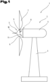
- Fig. 1 shows a schematic representation of a wind turbine 1 for generating electrical energy from wind energy.
- the wind turbine 1 comprises a nacelle 2, which is rotatably mounted on a tower 3.
- the nacelle 2 comprises a nacelle housing 4, which forms the main structure of the nacelle 2.
- the electrical components, such as a generator of the wind turbine 1, are arranged in the nacelle housing 4 of the nacelle 2.
- a rotor 5 is formed, which has a rotor hub 6 with rotor blades 7 arranged thereon.
- the rotor hub 6 is seen as part of the nacelle 2.
- the rotor hub 6 is rotatably mounted on the nacelle housing 4 by means of a rotor bearing 8.
- the axial force 10 is caused by the force of the wind.
- the radial force 9 is caused by the weight of the rotor 5 and acts on the center of gravity of the rotor 5. Since the center of gravity of the rotor 5 is outside the rotor bearing 8, the tilting moment 11 is caused in the rotor bearing 8 by the radial force 9.
- the tilting moment 11 can also be caused by an uneven load on the rotor blades 7.
- the rotor bearing 8 according to the invention can, for example, have a diameter between 0.5 m and 5 m. Of course, it is also conceivable that the rotor bearing 8 is smaller or larger.
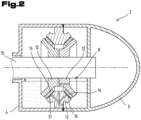
- Fig. 2 The nacelle housing 4 and the rotor hub 6 are shown in a schematic sectional view, whereby the structure, especially in its dimensions, has been highly schematized.
- the rotor bearing 8 has at least one inner ring element 12 and at least one outer ring element 13.
- At least one plain bearing element 14 is arranged between the inner ring element 12 and the outer ring element 13.
- the inner ring element 12 is coupled to the rotor hub 6.
- a rotor shaft 15 is formed on which the rotor hub 6 is arranged.
- the inner ring element 12 can be received directly on the rotor shaft 15.
- the inner ring element 12 is fastened to the nacelle housing 4 and that the rotor hub 6 is coupled to the outer ring element 13.
- both the inner ring element 12 and the outer ring element 13 are V-shaped and two sliding bearing elements 14 are formed on the V-shaped flank between the two ring elements 12, 13, spaced axially from each other, which are arranged at an angle to each other.
- the sliding bearing elements 14 are mounted directly on the inner ring element 12.
- a sliding surface 16 can be formed between the sliding bearing elements 14 and the outer ring element 13.
- the sliding surfaces 16 can also be arranged in a V shape.
- the inner ring element 12 is divided with respect to its axial extent or alternatively also along a central axis in order to facilitate the assembly of the rotor bearing 8.
- the inner ring element 12 is not as in Fig. 2 illustrated embodiment forms a groove, but the V-shaped arrangement is formed in reverse, so that a V-shaped projection is formed on the inner ring element 12.
- the outer ring element 13 is designed to be divided in its axial extent or alternatively also along a central axis.
- the individual parts of the split ring element 12, 13 are designed to be axially adjustable relative to one another in order to be able to compensate for the wear of the plain bearing elements 14, for example.
- the bearing gap can be adjusted by the axial adjustability of the individual parts of the ring elements 12, 13 relative to one another.
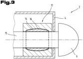
- FIG. 3 a further and possibly independent embodiment of the nacelle 2 is shown, whereby again the same reference numerals or component designations are used for the same parts as in the previous Figures 1 and 2 To avoid unnecessary repetition, please refer to the detailed description in the previous Figures 1 and 2 pointed out or referred to.
- the sliding bearing element 14 is designed as a coating which is applied directly to the inner ring element 12, wherein the inner ring element 12 is designed as an integral part of the rotor shaft 15 for receiving the rotor hub 6.
- the plain bearing element 14 has a sliding surface 16 in the form of a spherical cap.
- the plain bearing element 14 is designed for simultaneous radial and axial bearing of the rotor hub 6.
- the outer ring element 13 is designed as an integral part of a bearing block 17 accommodated in the nacelle housing 4.
- the bearing block 17 is divided along a central axis into an upper part and a lower part.
- the plain bearing element 14 is conical or V-shaped for simultaneous radial and axial bearing of the rotor hub 6.
- the plain bearing element 14 has a cylindrical radial plain bearing surface for simultaneous radial and axial bearing of the rotor hub 6 and has an axial plain bearing surface on the front side.
- This axial plain bearing surface can be designed in the form of a step, for example.
Landscapes
- Engineering & Computer Science (AREA)
- General Engineering & Computer Science (AREA)
- Mechanical Engineering (AREA)
- Sustainable Energy (AREA)
- Life Sciences & Earth Sciences (AREA)
- Sustainable Development (AREA)
- Manufacturing & Machinery (AREA)
- Chemical & Material Sciences (AREA)
- Combustion & Propulsion (AREA)
- Physics & Mathematics (AREA)
- Fluid Mechanics (AREA)
- Wind Motors (AREA)
- Sliding-Contact Bearings (AREA)
Applications Claiming Priority (3)
| Application Number | Priority Date | Filing Date | Title |
|---|---|---|---|
| DE102020112765.0A DE102020112765A1 (de) | 2020-05-12 | 2020-05-12 | Rotorhauptlagerung einer Gondel für eine Windkraftanlage |
| EP21728411.6A EP4150224B1 (fr) | 2020-05-12 | 2021-05-07 | Palier principal de rotor d'une nacelle pour une éolienne |
| PCT/AT2021/060159 WO2021226645A1 (fr) | 2020-05-12 | 2021-05-07 | Palier principal de rotor d'une nacelle pour une éolienne |
Related Parent Applications (1)
| Application Number | Title | Priority Date | Filing Date |
|---|---|---|---|
| EP21728411.6A Division EP4150224B1 (fr) | 2020-05-12 | 2021-05-07 | Palier principal de rotor d'une nacelle pour une éolienne |
Publications (1)
| Publication Number | Publication Date |
|---|---|
| EP4477902A1 true EP4477902A1 (fr) | 2024-12-18 |
Family
ID=76180816
Family Applications (2)
| Application Number | Title | Priority Date | Filing Date |
|---|---|---|---|
| EP24194950.2A Withdrawn EP4477902A1 (fr) | 2020-05-12 | 2021-05-07 | Support principal de rotor de nacelle pour éolienne |
| EP21728411.6A Active EP4150224B1 (fr) | 2020-05-12 | 2021-05-07 | Palier principal de rotor d'une nacelle pour une éolienne |
Family Applications After (1)
| Application Number | Title | Priority Date | Filing Date |
|---|---|---|---|
| EP21728411.6A Active EP4150224B1 (fr) | 2020-05-12 | 2021-05-07 | Palier principal de rotor d'une nacelle pour une éolienne |
Country Status (7)
| Country | Link |
|---|---|
| US (1) | US11873858B2 (fr) |
| EP (2) | EP4477902A1 (fr) |
| CN (1) | CN115516220B (fr) |
| DE (1) | DE102020112765A1 (fr) |
| DK (1) | DK4150224T3 (fr) |
| ES (1) | ES2993673T3 (fr) |
| WO (1) | WO2021226645A1 (fr) |
Families Citing this family (2)
| Publication number | Priority date | Publication date | Assignee | Title |
|---|---|---|---|---|
| CN221974112U (zh) * | 2023-12-21 | 2024-11-08 | 金雷科技股份公司 | 一种风电主轴一体化滑动轴承传动系统 |
| DE102024122667A1 (de) * | 2024-08-08 | 2026-02-12 | Schaeffler Technologies AG & Co. KG | Hauptlagergehäuse; Hauptlager für einen Rotor einer Windkraftanlage; Windkraftanlage mit einem Rotor; Verfahren zum Durchführen von Servicearbeiten an einem Hauptlager |
Citations (8)
| Publication number | Priority date | Publication date | Assignee | Title |
|---|---|---|---|---|
| AT509625A1 (de) * | 2010-04-14 | 2011-10-15 | Miba Gleitlager Gmbh | Lagerelement |
| EP2694810A2 (fr) | 2011-09-08 | 2014-02-12 | Siemens Aktiengesellschaft | Éolienne à entraînement direct |
| WO2014117197A1 (fr) * | 2013-01-30 | 2014-08-07 | Miba Gleitlager Gmbh | Transmission d'éolienne |
| WO2015110138A1 (fr) * | 2014-01-21 | 2015-07-30 | Aktiebolaget Skf | Construction de paliers de tangage comprenant des paliers lisses sphériques |
| EP3309393A1 (fr) * | 2016-10-12 | 2018-04-18 | Linde Hydraulics GmbH & Co. KG | Machine à déplacement volumétrique hydrostatique |
| WO2018071941A1 (fr) * | 2016-10-21 | 2018-04-26 | Miba Gleitlager Austria Gmbh | Élément de palier |
| WO2019020213A1 (fr) * | 2017-07-25 | 2019-01-31 | Rheinisch-Westfälische Technische Hochschule Aachen | Système de paliers lisses |
| WO2019178630A1 (fr) * | 2018-03-23 | 2019-09-26 | Miba Gleitlager Austria Gmbh | Transmission d'éolienne et procédé de fabrication d'une transmission d'éolienne |
Family Cites Families (2)
| Publication number | Priority date | Publication date | Assignee | Title |
|---|---|---|---|---|
| DE4008671A1 (de) * | 1990-03-17 | 1991-10-10 | Glyco Metall Werke | Radial-axialgleitlager in form von bundlager oder bundbuchse sowie verfahren zu seiner herstellung |
| AT15975U1 (de) * | 2017-05-23 | 2018-10-15 | Miba Gleitlager Austria Gmbh | Windkraftanlagengetriebe |
-
2020
- 2020-05-12 DE DE102020112765.0A patent/DE102020112765A1/de not_active Ceased
-
2021
- 2021-05-07 US US17/923,256 patent/US11873858B2/en active Active
- 2021-05-07 ES ES21728411T patent/ES2993673T3/es active Active
- 2021-05-07 WO PCT/AT2021/060159 patent/WO2021226645A1/fr not_active Ceased
- 2021-05-07 EP EP24194950.2A patent/EP4477902A1/fr not_active Withdrawn
- 2021-05-07 CN CN202180033403.4A patent/CN115516220B/zh active Active
- 2021-05-07 DK DK21728411.6T patent/DK4150224T3/da active
- 2021-05-07 EP EP21728411.6A patent/EP4150224B1/fr active Active
Patent Citations (9)
| Publication number | Priority date | Publication date | Assignee | Title |
|---|---|---|---|---|
| AT509625A1 (de) * | 2010-04-14 | 2011-10-15 | Miba Gleitlager Gmbh | Lagerelement |
| EP2694810A2 (fr) | 2011-09-08 | 2014-02-12 | Siemens Aktiengesellschaft | Éolienne à entraînement direct |
| EP2694810B1 (fr) | 2011-09-08 | 2015-11-25 | Siemens Aktiengesellschaft | Éolienne à entraînement direct |
| WO2014117197A1 (fr) * | 2013-01-30 | 2014-08-07 | Miba Gleitlager Gmbh | Transmission d'éolienne |
| WO2015110138A1 (fr) * | 2014-01-21 | 2015-07-30 | Aktiebolaget Skf | Construction de paliers de tangage comprenant des paliers lisses sphériques |
| EP3309393A1 (fr) * | 2016-10-12 | 2018-04-18 | Linde Hydraulics GmbH & Co. KG | Machine à déplacement volumétrique hydrostatique |
| WO2018071941A1 (fr) * | 2016-10-21 | 2018-04-26 | Miba Gleitlager Austria Gmbh | Élément de palier |
| WO2019020213A1 (fr) * | 2017-07-25 | 2019-01-31 | Rheinisch-Westfälische Technische Hochschule Aachen | Système de paliers lisses |
| WO2019178630A1 (fr) * | 2018-03-23 | 2019-09-26 | Miba Gleitlager Austria Gmbh | Transmission d'éolienne et procédé de fabrication d'une transmission d'éolienne |
Also Published As
| Publication number | Publication date |
|---|---|
| EP4150224B1 (fr) | 2024-08-21 |
| WO2021226645A1 (fr) | 2021-11-18 |
| DE102020112765A1 (de) | 2021-11-18 |
| US11873858B2 (en) | 2024-01-16 |
| EP4150224A1 (fr) | 2023-03-22 |
| CN115516220A (zh) | 2022-12-23 |
| CN115516220B (zh) | 2025-03-04 |
| ES2993673T3 (en) | 2025-01-03 |
| DK4150224T3 (da) | 2024-11-18 |
| US20230313833A1 (en) | 2023-10-05 |
Similar Documents
| Publication | Publication Date | Title |
|---|---|---|
| EP3768983B1 (fr) | Transmission d'éolienne et procédé de fabrication d'une transmission d'éolienne | |
| EP3529508B1 (fr) | Élément de palier | |
| AT521882B1 (de) | Gleitlager, insbesondere für ein Getriebe einer Windkraftanlage | |
| AT513516B1 (de) | Windkraftanlagengetriebe | |
| AT524520B1 (de) | Gleitlagerung, sowie eine mit der Gleitlagerung ausgestattete Gondel für eine Windkraftanlage | |
| EP4150224B1 (fr) | Palier principal de rotor d'une nacelle pour une éolienne | |
| WO2020232495A1 (fr) | Nacelle pour une éolienne | |
| WO2008031522A1 (fr) | Procédé de fabrication d'une bielle | |
| DE102010014689A1 (de) | Verfahren zum Beschichten einer Oberfläche eines Werkstücks, Motorblock-Rohteil und Motorblock | |
| EP1003924B1 (fr) | Procede de traitement thermique, notamment pour palier lisse | |
| EP4219970B1 (fr) | Procédé de fabrication d'un palier lisse multicouche | |
| DE102010039778B4 (de) | Rotorblatt für Windenergieanlagen | |
| EP3976286B1 (fr) | Palier lisse multicouche et procédé de fabrication d'un palier lisse multicouche | |
| EP1048389A2 (fr) | Protection pour la surface d'une pièce | |
| EP4446604A1 (fr) | Palier lisse multicouche, engrenage d'éolienne équipé d'un palier lisse multicouche et procédé de fabrication d'un palier lisse multicouche | |
| EP2206586B1 (fr) | Segment d'une scie à chaîne pour scies motorisées ultrarapides de scies à pierre, béton, tuile et métal | |
| DE102005022013B4 (de) | Fluiddynamisches Drucklager und Verfahren zum Verbinden von Bauteilen eines fluiddynamischen Drucklagers | |
| AT524211A4 (de) | Verfahren zum Verbinden eines ersten Bauteils mit einem zweiten Bauteil zu einer Baugruppe | |
| WO2024081982A1 (fr) | Élément de palier lisse | |
| WO1999006613A1 (fr) | Outils destines a l'usinage de pieces et procede de production de ces outils | |
| EP3850234A1 (fr) | Procédé de fabrication de cages de palier à roulement, en particulier de grandes cages de palier à roulement et cages de palier à roulement | |
| EP3431749B1 (fr) | Extenseur de fixation d'une pale de rotor sur un boîtier de noyau de rotor d'une éolienne, procédé de fabrication d'un extenseur et procédé de montage d'un extenseur | |
| EP4015776A1 (fr) | Disque de rotor et aube pour un étage de compresseur ou de turbine d'une turbine à gaz d'un moteur d'avion | |
| EP0399319A2 (fr) | Ferrure d'articulation pour sièges de véhicules automobiles |
Legal Events
| Date | Code | Title | Description |
|---|---|---|---|
| PUAI | Public reference made under article 153(3) epc to a published international application that has entered the european phase |
Free format text: ORIGINAL CODE: 0009012 |
|
| STAA | Information on the status of an ep patent application or granted ep patent |
Free format text: STATUS: THE APPLICATION HAS BEEN PUBLISHED |
|
| AC | Divisional application: reference to earlier application |
Ref document number: 4150224 Country of ref document: EP Kind code of ref document: P |
|
| AK | Designated contracting states |
Kind code of ref document: A1 Designated state(s): AL AT BE BG CH CY CZ DE DK EE ES FI FR GB GR HR HU IE IS IT LI LT LU LV MC MK MT NL NO PL PT RO RS SE SI SK SM TR |
|
| STAA | Information on the status of an ep patent application or granted ep patent |
Free format text: STATUS: THE APPLICATION IS DEEMED TO BE WITHDRAWN |
|
| 18D | Application deemed to be withdrawn |
Effective date: 20250619 |