EP0399319A2 - Hinge fitting for motor vehicle seats - Google Patents
Hinge fitting for motor vehicle seats Download PDFInfo
- Publication number
- EP0399319A2 EP0399319A2 EP90108984A EP90108984A EP0399319A2 EP 0399319 A2 EP0399319 A2 EP 0399319A2 EP 90108984 A EP90108984 A EP 90108984A EP 90108984 A EP90108984 A EP 90108984A EP 0399319 A2 EP0399319 A2 EP 0399319A2
- Authority
- EP
- European Patent Office
- Prior art keywords
- joint
- hinge
- fitting according
- spur gear
- eccentric
- Prior art date
- Legal status (The legal status is an assumption and is not a legal conclusion. Google has not performed a legal analysis and makes no representation as to the accuracy of the status listed.)
- Granted
Links
- 238000004519 manufacturing process Methods 0.000 description 4
- 230000002349 favourable effect Effects 0.000 description 2
- 238000004049 embossing Methods 0.000 description 1
- 238000001125 extrusion Methods 0.000 description 1
- 239000000463 material Substances 0.000 description 1
- 239000002184 metal Substances 0.000 description 1
- 238000005096 rolling process Methods 0.000 description 1
Images
Classifications
-
- B—PERFORMING OPERATIONS; TRANSPORTING
- B60—VEHICLES IN GENERAL
- B60N—SEATS SPECIALLY ADAPTED FOR VEHICLES; VEHICLE PASSENGER ACCOMMODATION NOT OTHERWISE PROVIDED FOR
- B60N2/00—Seats specially adapted for vehicles; Arrangement or mounting of seats in vehicles
- B60N2/02—Seats specially adapted for vehicles; Arrangement or mounting of seats in vehicles the seat or part thereof being movable, e.g. adjustable
- B60N2/22—Seats specially adapted for vehicles; Arrangement or mounting of seats in vehicles the seat or part thereof being movable, e.g. adjustable the back-rest being adjustable
- B60N2/225—Seats specially adapted for vehicles; Arrangement or mounting of seats in vehicles the seat or part thereof being movable, e.g. adjustable the back-rest being adjustable by cycloidal or planetary mechanisms
- B60N2/2254—Seats specially adapted for vehicles; Arrangement or mounting of seats in vehicles the seat or part thereof being movable, e.g. adjustable the back-rest being adjustable by cycloidal or planetary mechanisms provided with braking systems
-
- B—PERFORMING OPERATIONS; TRANSPORTING
- B60—VEHICLES IN GENERAL
- B60N—SEATS SPECIALLY ADAPTED FOR VEHICLES; VEHICLE PASSENGER ACCOMMODATION NOT OTHERWISE PROVIDED FOR
- B60N2/00—Seats specially adapted for vehicles; Arrangement or mounting of seats in vehicles
- B60N2/02—Seats specially adapted for vehicles; Arrangement or mounting of seats in vehicles the seat or part thereof being movable, e.g. adjustable
- B60N2/22—Seats specially adapted for vehicles; Arrangement or mounting of seats in vehicles the seat or part thereof being movable, e.g. adjustable the back-rest being adjustable
- B60N2/225—Seats specially adapted for vehicles; Arrangement or mounting of seats in vehicles the seat or part thereof being movable, e.g. adjustable the back-rest being adjustable by cycloidal or planetary mechanisms
- B60N2/2252—Seats specially adapted for vehicles; Arrangement or mounting of seats in vehicles the seat or part thereof being movable, e.g. adjustable the back-rest being adjustable by cycloidal or planetary mechanisms in which the central axis of the gearing lies inside the periphery of an orbital gear, e.g. one gear without sun gear
Definitions
- the invention relates to a joint fitting for motor vehicle seats according to the preamble of claim 1.
- a known joint fitting (DE-OS 37 09 403) the spur gear is formed in one piece with the joint part and protrudes axially on one side beyond the joint part.
- the spur gear meshes with an internal toothing which is formed on the other joint part. Due to the asymmetrical structure, the known fitting is susceptible to transverse forces and torsional moments around the longitudinal axis of the joint parts.
- the asymmetrical design of the joint also requires a complex axial fixation.
- the invention is therefore based on the object to provide a stable joint fitting by simple means, which is characterized by a particularly favorable flow of force and is associated with a low manufacturing and assembly costs. This object is achieved by the characterizing features of claim 1.
- an articulated fitting which has a spur gear mounted on an eccentric, which meshes with internal toothings which are provided on articulated parts which axially surround the spur gear from one side in each case.
- the inner ring gears have different numbers of teeth and are each a different joint part assigned.
- the spur gear is not connected to any joint part, but merely serves to twist the two internally toothed joint parts against one another.
- An embodiment of the invention in which the spur gear is press-fitted to the second joint part in the form of a toothed shaft-hub connection is particularly favorable in terms of manufacture. Due to this two-piece design, different materials can be used for the joint part and gear. If this is not necessary, an embodiment is also possible in which the spur gear and the joint part are formed in one piece and the external toothing is produced, for example, by embossing on both sides or by extrusion. For a cost-effective production z. B. also a version that is composed of two shell-shaped half profiles, a half profile with an additional spur gear or a flat sheet metal part with two laterally arranged spur gears.
- a particularly great stability against rotation about the longitudinal axis of the joint parts is achieved in that the sections are plate-shaped and rest with their radially outer regions on the second joint part.
- An embodiment which can be assembled with particularly little effort since no additional fastening elements are required is characterized in that the sections abut the end faces of the eccentric and that the joint axially secures the drive shaft.
- the eccentric is of course firmly connected to the drive shaft, or is integrally formed with the same.
- the hinge fitting has a first hinge part 1, which is connected to a seat back, not shown.
- the seat also not shown, is connected to the second joint part 2.
- the second joint part 2 is punched out with an opening in the form of a Spur gear.
- a spur gear 3 having an external toothing 6 with the same shape and with a slight oversize is pressed into this internal toothing 7.
- the spur gear 3 has a greater width than the second joint part 2 and is arranged in the latter such that it protrudes axially on both sides by the same amount.
- the gear 3 is mounted on the eccentric 11 by means of a roller bearing, which is arranged on the drive shaft 10.
- the drive shaft 10 is provided with a recess 12 with a non-circular cross section, which serves as a driver device for receiving a handwheel or an electric drive.
- the eccentric 11 has the same width as the spur gear 3.
- the sections 4, 5 are identical and have an internal toothing 8 or 9, the tip circle diameter of which is larger than that of the external toothing 6 of the spur gear 3; the number of teeth of the internal toothing 8.9 is greater than the number of teeth of the external toothing.
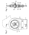
- the head, rolling and root circle diameters of the toothings are shown in FIG. 1, which shows a side view with missing section 4, by different line types.
Landscapes
- Engineering & Computer Science (AREA)
- Aviation & Aerospace Engineering (AREA)
- Transportation (AREA)
- Mechanical Engineering (AREA)
- Chairs For Special Purposes, Such As Reclining Chairs (AREA)
- Retarders (AREA)
- Gears, Cams (AREA)
Abstract
Description
Die Erfindung betrifft einen Gelenkbeschlag für Kraftfahrzeugsitze nach dem Oberbegriff des Patentanspruches 1. Bei einem bekannten Gelenkbeschlag (DE-OS 37 09 403) ist das Stirnrad einstückig mit dem Gelenkteil ausgebildet und ragt auf einer Seite axial über das Gelenkteil hervor. Das Stirnrad kämmt mit einer Innenverzahnung, welche am anderen Gelenkteil ausgebildet ist. Der bekannte Beschlag ist durch den unsymmetrischen Aufbau anfällig gegen Querkräfte und Torsionsmomente um die Längsachse der Gelenkteile. Die unsymmetrische Ausbildung des Gelenkes erfordert auch eine aufwendige axiale Fixierung.The invention relates to a joint fitting for motor vehicle seats according to the preamble of claim 1. In a known joint fitting (DE-OS 37 09 403) the spur gear is formed in one piece with the joint part and protrudes axially on one side beyond the joint part. The spur gear meshes with an internal toothing which is formed on the other joint part. Due to the asymmetrical structure, the known fitting is susceptible to transverse forces and torsional moments around the longitudinal axis of the joint parts. The asymmetrical design of the joint also requires a complex axial fixation.
Der Erfindung liegt daher die Aufgabe zugrunde, durch einfache Mittel einen stabilen Gelenkbeschlag zu schaffen, die sich durch einen besonders günstigen Kraftflußverlauf auszeichnet und dabei mit einem geringen Herstellungs- und Montageaufwand verbunden ist. Diese Aufgabe wird erfindungsgemäß durch die kennzeichnenden Merkmale des Ansprüches 1 gelöst.The invention is therefore based on the object to provide a stable joint fitting by simple means, which is characterized by a particularly favorable flow of force and is associated with a low manufacturing and assembly costs. This object is achieved by the characterizing features of claim 1.
Aus der DE-OS 29 18 252 ist zwar ein Gelenkbeschlag bekannt, welcher ein auf einem Exzenter gelagertes Stirnzahnrad besitzt, welches mit Innenverzahnungen kämmt, welche an Gelenkteilen vorgesehen sind, die das Stirnzahnrad axial von jeweils einer Seite umgeben. Dabei weisen allerdings die Innenzahnkränze unterschiedliche Zähnezahl auf und sind jeweils einem anderen Gelenkteil zugeordnet. Das Stirnzahnrad ist mit keinem Gelenkteil verbunden, sondern dient lediglich der Verdrehung der beiden innenverzahnten Gelenkteile gegeneinander. Bei diesem bekannten Gelenkbeschlag treten in bezug auf die Stabilität die gleichen Probleme auf, wie bei derjenigen gemäß DE-OS 37 09 403.From DE-OS 29 18 252 an articulated fitting is known, which has a spur gear mounted on an eccentric, which meshes with internal toothings which are provided on articulated parts which axially surround the spur gear from one side in each case. However, the inner ring gears have different numbers of teeth and are each a different joint part assigned. The spur gear is not connected to any joint part, but merely serves to twist the two internally toothed joint parts against one another. With this known joint fitting, the same problems arise with regard to stability as with that according to DE-OS 37 09 403.
Besonders günstig in der Herstellung ist eine Ausführung der Erfindung, bei welcher das Stirnrad in Form einer verzahnten Wellen-Naben-Verbindung mit Preßsitz mit dem zweiten Gelenkteil verbunden ist. Durch diese Zweistückigkeit können unterschiedliche Materialien für Gelenkteil und Zahnrad benutzt werden. Ist dies nicht erforderlich, so ist auch eine Ausführung möglich, bei welcher Stirnrad und Gelenkteil einstückig ausgebildet sind und die Außenverzahnung beispielsweise durch beidseitiges Prägen oder Fließpressen hergestellt wird. Für eine kostengünstige Fertigung eignet sich z. B. auch eine Ausführung, die sich aus zwei schalenförmigen Halbprofilen zusammensetzt, ein Halbprofil mit zusätzlichem Stirnrad oder ein ebenes Blechteil mit zwei seitlich angeordneten Stirnrädern.An embodiment of the invention in which the spur gear is press-fitted to the second joint part in the form of a toothed shaft-hub connection is particularly favorable in terms of manufacture. Due to this two-piece design, different materials can be used for the joint part and gear. If this is not necessary, an embodiment is also possible in which the spur gear and the joint part are formed in one piece and the external toothing is produced, for example, by embossing on both sides or by extrusion. For a cost-effective production z. B. also a version that is composed of two shell-shaped half profiles, a half profile with an additional spur gear or a flat sheet metal part with two laterally arranged spur gears.
Damit der Drehsinn der Antriebswelle mit der Schwenkbewegung der Rückenlehne übereinstimmt, ist es sinnvoll, das zweite Gelenkteil der Sitzfläche und das erste Gelenkteil der Lehne zuzuordnen. Durch Verspannen der beiden Abschnitte des ersten Gelenkteils gegeneinander, läßt sich das Spiel im Gelenk auf ein Minimum einstellen. So lassen sich Fertigungstoleranzen aus besonders einfache Art eliminieren.So that the direction of rotation of the drive shaft coincides with the pivoting movement of the backrest, it makes sense to assign the second joint part to the seat surface and the first joint part to the backrest. By tightening the two sections of the first joint part against each other, the play in the joint can be set to a minimum. In this way, manufacturing tolerances can be eliminated from a particularly simple manner.
Eine besonders große Stabilität gegen Verdrehung um die Längsachse der Gelenkteile wird dadurch erreicht, daß die Abschnitte tellerförmig ausgebildet sind und mit ihren radial äußeren Bereichen am zweiten Gelenkteil anliegen. Eine mit besonders geringeren Aufwand zu montierende, da ohne zusätzliche Befestigungselemente auskommende Ausführungsform, zeichnet sich dadurch aus, daß die Abschnitte an den Stirnseiten des Exzenters anliegen und daß Gelenk axial auf der Antriebswelle sichern. Bei dieser Ausführungsform ist natürlich der Exzenter fest mit der Antriebswelle verbunden, bzw. einstückig mit derselben ausgebildet.A particularly great stability against rotation about the longitudinal axis of the joint parts is achieved in that the sections are plate-shaped and rest with their radially outer regions on the second joint part. An embodiment which can be assembled with particularly little effort since no additional fastening elements are required is characterized in that the sections abut the end faces of the eccentric and that the joint axially secures the drive shaft. In this embodiment, the eccentric is of course firmly connected to the drive shaft, or is integrally formed with the same.
Weitere vorteilhafte Merkmale, sowie die Funktion der Erfindung ergeben sich aus der nachstehenden Beschreibung eines Ausführungsbeispiels der Erfindung anhand der Zeichnungen.Further advantageous features and the function of the invention result from the following description of an embodiment of the invention with reference to the drawings.
Hierzu zeigt:
- Fig. 1 eine Seitenansicht des Gelenkbeschlages
- Fig. 2 einen Schnitt durch den Gelenkbeschlag gemäß Linie A-A der Fig. 1
- Fig. 1 is a side view of the hinge fitting
- 2 shows a section through the hinge fitting along line AA of FIG. 1st
Der Gelenkbeschlag weist ein erste Gelenkteil 1 auf, welches mit einer nicht dargestellten Sitzlehne verbunden ist. Die ebenfalls nicht dargestellte Sitzfläche ist mit dem zweiten Gelenkteil 2 verbunden. Das zweite Gelenkteil 2 ist mit einer Öffnung in Form eines herausgestanzten Stirnrades versehen. In diese Innenverzahnung 7 ist ein eine Außenverzahnung 6 aufweisendes Stirnrad 3 mit gleicher Form und mit geringem Übermaß hineingepreßt. Das Stirnrad 3 besitzt eine größere Breite als das zweite Gelenkteil 2 und ist derart in Letzterem angeordnet, daß es axial auf beiden Seiten um das gleiche Maß hervorsteht. Das Zahnrad 3 ist mittels eines Rollenlagers auf dem Exzenter 11 gelagert, welcher auf der Antriebswelle 10 angeordnet ist. Die Antriebswelle 10 ist mit einer Ausnehmung 12 mit unrundem Querschnitt versehen, die als Mitnehmervorrichtung zur Aufnahme eines Handrades oder eines Elektroantriebs dient.The hinge fitting has a first hinge part 1, which is connected to a seat back, not shown. The seat, also not shown, is connected to the second joint part 2. The second joint part 2 is punched out with an opening in the form of a Spur gear. A
Der Exzenter 11 weist dieselbe Breite wie das Stirnrad 3 auf. An deren Stirnflächen liegen die tellerförmigen Abschnitte 4 und 5 an, welche durch eine Nietverbindung mit dem ersten Gelenkteil 1 verbunden sind. Die Abschnitte 4,5 sind identisch und weisen eine Innenverzahnung 8 bzw. 9 auf, deren Kopfkreisdurchmesser größer ist als derjenige der Außenverzahnung 6 des Stirnrades 3; die Zähnezahl der Innenverzahnung 8,9 ist größer als die Zähnezahl der Außenverzahnung. Die Kopf-, Wälz- und Fußkreisdurchmesser der Verzahnungen sind in Fig. 1, die eine Seitenansicht mit fehlendem Abschnitt 4 zeigt, durch unterschiedliche Stricharten dargestellt.The eccentric 11 has the same width as the
Die radial äußeren Bereiche der Abschnitte 4,5 sind in axialer Anlage am ersten Gelenkteil 1. In der Zeichnung befindet sich der Exzenter 11 in seiner maximal nach oben ausgelenkten Position, so daß die Außenverzahnung 6 des Stirnrades 3 über eine bestimmte Bogenlänge mit dem oberen Bereich der Innenverzahnung 8,9 in Eingriff steht. Auf der gegenüberliegenden Seite ist ein Abstand zwischen den Kopfkreisen der Außenverzahnung 6 und der Innenverzahnung 8,9.The radially outer regions of the
Wird nun die Antriebswelle 10 gedreht, so kämmt das Stirnrad 3 durch die aufgezwungene exzentrische Bewegung mit der Innenverzahnung 8,9 der Abschnitte 4,5. Durch die unterschiedliche Anzahl der Zähne werden die Gelenkteile 1,2 um einen bestimmten Winkel gegeneinander verschwenkt.If the
- 1 erstes Gelenkteil1 first joint part
- 2 zweites Gelenkteil2 second joint part
- 3 Stirnrad3 spur gear
- 4 Abschnitt4 section
- 5 Abschnitt5 section
- 6 Außenverzahnung6 external teeth
- 7 Innenverzahnung7 internal teeth
- 8 Innenverzahnung8 internal teeth
- 9 Innenverzahnung9 internal teeth
- 10 Antriebswelle10 drive shaft
- 11 Exzenter11 eccentrics
- 12 Ausnehmung12 recess
Claims (10)
Applications Claiming Priority (2)
| Application Number | Priority Date | Filing Date | Title |
|---|---|---|---|
| DE3916673A DE3916673A1 (en) | 1989-05-23 | 1989-05-23 | JOINT FITTING FOR MOTOR VEHICLE SEATS |
| DE3916673 | 1989-05-23 |
Publications (3)
| Publication Number | Publication Date |
|---|---|
| EP0399319A2 true EP0399319A2 (en) | 1990-11-28 |
| EP0399319A3 EP0399319A3 (en) | 1991-10-23 |
| EP0399319B1 EP0399319B1 (en) | 1995-01-25 |
Family
ID=6381176
Family Applications (1)
| Application Number | Title | Priority Date | Filing Date |
|---|---|---|---|
| EP90108984A Expired - Lifetime EP0399319B1 (en) | 1989-05-23 | 1990-05-12 | Hinge fitting for motor vehicle seats |
Country Status (3)
| Country | Link |
|---|---|
| EP (1) | EP0399319B1 (en) |
| DE (2) | DE3916673A1 (en) |
| ES (1) | ES2066903T3 (en) |
Families Citing this family (2)
| Publication number | Priority date | Publication date | Assignee | Title |
|---|---|---|---|---|
| US5542772A (en) * | 1990-11-22 | 1996-08-06 | Alfred Teves Gmbh & Co Ohg | Articulated joint fitting for automotive vehicle seat |
| EP0513254B1 (en) * | 1990-11-22 | 1997-01-29 | Alfred Teves GmbH & Co. OHG | Hinge mounting for vehicle seats |
Citations (5)
| Publication number | Priority date | Publication date | Assignee | Title |
|---|---|---|---|---|
| FR2398637A1 (en) * | 1977-07-30 | 1979-02-23 | Keiper Automobiltechnik Gmbh | JOINT HINGE FOR SEAT WITH ADJUSTABLE BACKREST, IN PARTICULAR FOR MOTOR VEHICLE SEATS |
| DE3129672C1 (en) * | 1981-07-28 | 1982-10-28 | Privates Institut für physikalisch technische Auftragsforschung GmbH, 6107 Reinheim | Locking and adjusting mechanism for vehicle seat - includes locking and adjusting drives with toothed arms and eccentric bushes |
| DE3241088A1 (en) * | 1981-11-25 | 1983-06-01 | Keiper Automobiltechnik Gmbh & Co Kg, 5630 Remscheid | JOINT FITTING FOR BACKRESTS OF VEHICLE SEATS |
| DE3529887A1 (en) * | 1985-08-21 | 1987-03-05 | Keiper Recaro Gmbh Co | JOINT FITTING |
| GB2219735A (en) * | 1988-06-14 | 1989-12-20 | Honda Motor Co Ltd | Reclining device for a vehicle seat |
-
1989
- 1989-05-23 DE DE3916673A patent/DE3916673A1/en not_active Withdrawn
-
1990
- 1990-05-12 DE DE59008332T patent/DE59008332D1/en not_active Expired - Fee Related
- 1990-05-12 EP EP90108984A patent/EP0399319B1/en not_active Expired - Lifetime
- 1990-05-12 ES ES90108984T patent/ES2066903T3/en not_active Expired - Lifetime
Patent Citations (5)
| Publication number | Priority date | Publication date | Assignee | Title |
|---|---|---|---|---|
| FR2398637A1 (en) * | 1977-07-30 | 1979-02-23 | Keiper Automobiltechnik Gmbh | JOINT HINGE FOR SEAT WITH ADJUSTABLE BACKREST, IN PARTICULAR FOR MOTOR VEHICLE SEATS |
| DE3129672C1 (en) * | 1981-07-28 | 1982-10-28 | Privates Institut für physikalisch technische Auftragsforschung GmbH, 6107 Reinheim | Locking and adjusting mechanism for vehicle seat - includes locking and adjusting drives with toothed arms and eccentric bushes |
| DE3241088A1 (en) * | 1981-11-25 | 1983-06-01 | Keiper Automobiltechnik Gmbh & Co Kg, 5630 Remscheid | JOINT FITTING FOR BACKRESTS OF VEHICLE SEATS |
| DE3529887A1 (en) * | 1985-08-21 | 1987-03-05 | Keiper Recaro Gmbh Co | JOINT FITTING |
| GB2219735A (en) * | 1988-06-14 | 1989-12-20 | Honda Motor Co Ltd | Reclining device for a vehicle seat |
Also Published As
| Publication number | Publication date |
|---|---|
| DE59008332D1 (en) | 1995-03-09 |
| ES2066903T3 (en) | 1995-03-16 |
| EP0399319A3 (en) | 1991-10-23 |
| EP0399319B1 (en) | 1995-01-25 |
| DE3916673A1 (en) | 1990-11-29 |
Similar Documents
| Publication | Publication Date | Title |
|---|---|---|
| EP2836416B1 (en) | Floating bearing for a steering gear | |
| EP2398671B1 (en) | Fitting for a vehicle seat | |
| DE3006331C2 (en) | transmission | |
| DE102008011147B4 (en) | Backlash free planetary gear with split planetary gears, which are biased by arranged parallel to the planetary rotation axis biasing elements | |
| DE3738924C2 (en) | ||
| DE2849542C2 (en) | Articulated fitting for seats with adjustable backrests, in particular motor vehicle seats | |
| DE3226714C2 (en) | Articulated fitting for motor vehicle seats with adjustable backrest | |
| EP0918671B1 (en) | Electric drive unit | |
| DE10120854C1 (en) | Gear fitting for a vehicle seat adjuster | |
| EP2015958B1 (en) | Adjustment fitting for a motor vehicle component, and method for securing the locking effect of an adjustment fitting | |
| DE2734568A1 (en) | ARTICULATED FITTING FOR SEATS WITH ADJUSTABLE BACKREST, IN PARTICULAR MOTOR VEHICLE SEATS | |
| DE69803477T2 (en) | DRUM MOTOR | |
| DE3118896C2 (en) | Swivel joint, especially for seats with adjustable backrests | |
| EP1298353B1 (en) | Gear pair and use thereof | |
| DE3130313A1 (en) | SWIVEL, IN PARTICULAR FOR SEATS WITH ADJUSTABLE BACKREST | |
| EP3828442A1 (en) | Flexible toothed wheel and transmission comprising such a flexible toothed wheel | |
| DE2735958B2 (en) | Steering gears for automobiles | |
| EP0802348A2 (en) | Transmission unit | |
| DE19729452C2 (en) | Adapter component | |
| EP3768994A1 (en) | Planetary gearbox having single-tooth sun gear having evoloid toothing | |
| EP0399319A2 (en) | Hinge fitting for motor vehicle seats | |
| DE3034133C2 (en) | Planetary gear | |
| DE102006047061B4 (en) | Play free hinge fitting for an adjustment of a motor vehicle seat | |
| WO2005073053A1 (en) | Rack-and-pinion steering gear | |
| DE4217123C2 (en) | Backrest for vehicle seats, in particular motor vehicle seats |
Legal Events
| Date | Code | Title | Description |
|---|---|---|---|
| PUAI | Public reference made under article 153(3) epc to a published international application that has entered the european phase |
Free format text: ORIGINAL CODE: 0009012 |
|
| 17P | Request for examination filed |
Effective date: 19900512 |
|
| AK | Designated contracting states |
Kind code of ref document: A2 Designated state(s): DE ES FR GB IT |
|
| PUAL | Search report despatched |
Free format text: ORIGINAL CODE: 0009013 |
|
| AK | Designated contracting states |
Kind code of ref document: A3 Designated state(s): DE ES FR GB IT |
|
| 17Q | First examination report despatched |
Effective date: 19921029 |
|
| RAP1 | Party data changed (applicant data changed or rights of an application transferred) |
Owner name: ITT AUTOMOTIVE EUROPE GMBH |
|
| ITF | It: translation for a ep patent filed | ||
| GRAA | (expected) grant |
Free format text: ORIGINAL CODE: 0009210 |
|
| AK | Designated contracting states |
Kind code of ref document: B1 Designated state(s): DE ES FR GB IT |
|
| GBT | Gb: translation of ep patent filed (gb section 77(6)(a)/1977) |
Effective date: 19950203 |
|
| REF | Corresponds to: |
Ref document number: 59008332 Country of ref document: DE Date of ref document: 19950309 |
|
| REG | Reference to a national code |
Ref country code: ES Ref legal event code: FG2A Ref document number: 2066903 Country of ref document: ES Kind code of ref document: T3 |
|
| ET | Fr: translation filed | ||
| PLBE | No opposition filed within time limit |
Free format text: ORIGINAL CODE: 0009261 |
|
| STAA | Information on the status of an ep patent application or granted ep patent |
Free format text: STATUS: NO OPPOSITION FILED WITHIN TIME LIMIT |
|
| 26N | No opposition filed | ||
| PGFP | Annual fee paid to national office [announced via postgrant information from national office to epo] |
Ref country code: GB Payment date: 19990419 Year of fee payment: 10 |
|
| PGFP | Annual fee paid to national office [announced via postgrant information from national office to epo] |
Ref country code: FR Payment date: 19990518 Year of fee payment: 10 |
|
| PGFP | Annual fee paid to national office [announced via postgrant information from national office to epo] |
Ref country code: DE Payment date: 19990608 Year of fee payment: 10 |
|
| PG25 | Lapsed in a contracting state [announced via postgrant information from national office to epo] |
Ref country code: GB Free format text: LAPSE BECAUSE OF NON-PAYMENT OF DUE FEES Effective date: 20000512 |
|
| PGFP | Annual fee paid to national office [announced via postgrant information from national office to epo] |
Ref country code: ES Payment date: 20000516 Year of fee payment: 11 |
|
| GBPC | Gb: european patent ceased through non-payment of renewal fee |
Effective date: 20000512 |
|
| PG25 | Lapsed in a contracting state [announced via postgrant information from national office to epo] |
Ref country code: FR Free format text: LAPSE BECAUSE OF NON-PAYMENT OF DUE FEES Effective date: 20010131 |
|
| PG25 | Lapsed in a contracting state [announced via postgrant information from national office to epo] |
Ref country code: DE Free format text: LAPSE BECAUSE OF NON-PAYMENT OF DUE FEES Effective date: 20010301 |
|
| REG | Reference to a national code |
Ref country code: FR Ref legal event code: ST |
|
| PG25 | Lapsed in a contracting state [announced via postgrant information from national office to epo] |
Ref country code: ES Free format text: LAPSE BECAUSE OF NON-PAYMENT OF DUE FEES Effective date: 20010514 |
|
| REG | Reference to a national code |
Ref country code: ES Ref legal event code: FD2A Effective date: 20030203 |
|
| PG25 | Lapsed in a contracting state [announced via postgrant information from national office to epo] |
Ref country code: IT Free format text: LAPSE BECAUSE OF NON-PAYMENT OF DUE FEES;WARNING: LAPSES OF ITALIAN PATENTS WITH EFFECTIVE DATE BEFORE 2007 MAY HAVE OCCURRED AT ANY TIME BEFORE 2007. THE CORRECT EFFECTIVE DATE MAY BE DIFFERENT FROM THE ONE RECORDED. Effective date: 20050512 |